
Study on Composite Fracture Characteristics and Hydraulic Fracturing Behavior of Hard Rock


1
School of Resources & Environment and Safety Engineering, Hunan University of Science and Technology, Xiangtan 411201, China
2
School of Civil Engineering, Hunan University of Science and Technology, Xiangtan 411201, China
3
School of Building Engineering, Hunan Institute of Engineering, Xiangtan 411201, China
*
Author to whom correspondence should be addressed.
Appl. Sci. 2024, 14(6), 2585; https://doi.org/10.3390/app14062585
Submission received: 30 January 2024
/
Revised: 6 March 2024
/
Accepted: 18 March 2024
/
Published: 20 March 2024
(This article belongs to the Special Issue Urban Underground Engineering: Excavation, Monitoring, and Control: 2nd Edition)
Abstract
:To investigate the influence of non-singular terms (T stress) in the stress field on the composite fractures of hard rock Type I–II, such as rock splitting failure and hydraulic fracture propagation, this study focused on hard rocks in metallic mines. Through splitting tests and hydraulic fracturing experiments, the impact of T stress on the characteristics of Type I–II composite fractures in hard rocks was analyzed. Utilizing the generalized maximum tangential (GMTS) stress criterion considering T stress, the stress intensity factors of hard rock Type I–II composite fractures with different pre-existing crack angles were predicted. The critical fracture pressure expression for hard rocks was derived based on the maximum tangential stress (MTS) criterion. The results indicate that the GMTS criterion, considering T stress, is more suitable for describing the characteristics of Type I–II composite fractures under rock-splitting loads. However, under hydraulic fracturing, T stress has a minor influence on the fracture characteristics of hard rock hydraulic fractures. Therefore, when predicting the critical fracture pressure of hydraulic fractures, T stress can be disregarded. This study provides a scientific basis and guidance for hard rock hydraulic fracturing engineering.
1. Introduction
Studying the characteristics of Type I–II composite fractures in hard rocks enables theoretical predictions of the fracturing behavior of ore rocks and serves as a foundational research basis for establishing mechanisms of rock breaking under hydraulic fracturing conditions [1,2,3,4,5].
In the field of fracture mechanics, a variety of traditional composite fracture criteria have been proposed to predict the linear elastic fracture behavior of cracked materials [6]. These criteria include the maximum shear stress criterion proposed by Erdogan et al. [7], the strain energy density factor theory proposed by Sih [8], and the maximum energy release rate theory developed based on the Griffith theory [9]. They analyzed the fracture characteristics of the material by considering the singular term of the stress field at the crack tip. However, studies have shown that there are significant differences between the prediction results of the traditional composite fracture criterion and the experimental observation results, mainly due to the influence of the non-singular term (T stress) in the stress field of the crack tip [10,11,12,13,14,15]. Therefore, to more accurately analyze the fracture characteristics of materials, scholars began to retain the non-singular term (T stress) in the stress field. This concept was first proposed by Williams and Ewing [16] and led to the development of the generalized maximum shear stress criterion [17], the generalized minimum strain energy density factor criterion [18], and the generalized average strain energy density factor criterion [19].
The impact of T stress on material fracture characteristics is closely related to the critical fracture distance, and the greater the critical fracture distance, the greater the influence of T stress on material fracture characteristics [20]. Hard rocks, as brittle materials, are generally considered to have a very small critical fracture distance [21]. Currently, there has been a considerable amount of research on the influence of T stress on the fracture characteristics of brittle materials. For example, Li et al. [22] derived analytical formulas for T stress in edge-cracked Brazilian disc (ECBD) specimens under distributed loads and found that its influence should be considered for larger crack angles. Shen et al. [23] modified the traditional G criterion, considering the influence of T stress on crack propagation. Tang et al. considered the influence of T stress and established the maximum tangential stress (MTS) criterion that simultaneously considers rock properties, crack parameters, strength, and deformation parameters, predicting Type I–II composite stress intensity factors [24].
Under the combined influence of in situ stress and hydraulic pressure, hydraulic fractures often exhibit Type I–II composite fractures [25,26,27]. Existing theoretical research calculates Type I–II composite stress intensity factors at the tip of hydraulic fractures by modeling without considering the wellbore, simplifying it as a model with inclined cracks in an infinite plate [28,29,30]. Moreover, hydraulic fracturing rocks are often treated as brittle materials, and to simplify calculations, linear elastic fracture criteria are used to describe the rock-breaking process of hydraulic fractures [31,32,33,34].
The effect of T stress on the fracture characteristics of brittle materials was investigated. Based on the generalized maximum tangential stress (GMTS) criterion, the effect of T stress on the fracture characteristics of hard rock is verified in the splitting test. In addition, we also analyze the influence of T stress on the fracture characteristics of hydraulic fracturing and derive the calculation formula for the critical fracture pressure of hydraulic fracturing. Compared with the existing research, the main innovation of this study is that the influence of T stress on the hard rock fracture process is fully considered, which provides an important theoretical basis for hard rock hydraulic fracturing engineering. These findings provide new insights to the scientific community in understanding hard rock hydraulic fracturing behavior and provide a valuable reference for future related research and engineering practices.
2. Composite Fracture Characteristics in the Fracture Toughness Test
2.1. The GMTS Criterion
Considering that there are more I–II composite faults [35,36,37,38] in rock engineering, and I–II composite faults only crack on the fracture cross-section [39], this study conducted theoretical analysis on the fracture cross-section. This study considered the influence of non-singular terms on the fracture of medium cracks and represented the stress field at the crack tip using the stress intensity factors KI, KII, and T stress, as shown below [40]:
In this equation, σr, σθ, and τrθ represent the radial stress, tangential stress, and shear stress at the crack tip, respectively, measured in megapascals (MPa). The variables r and θ denote the radius and angle at the crack tip, measured in millimeters (mm) and degrees (°), respectively. KI and KII are the stress intensity factors for Mode I and Mode II cracks, measured in megapascals per square root meter (MPa·m−1/2), respectively. T is the non-singular term of the stress field, i.e., T stress, representing the stress component parallel to the crack direction, measured in megapascals (MPa).
The MTS theory was primarily employed to explain the fracture problems associated with Mode I, Mode II, and Mode I–II compound cracks. This criterion posits the following:
- Cracks initiate at the crack tip radially in the direction of the maximum tangential stress σθ.
- Based on the tangential stress σθ achieving its maximum value σθmax, the angle of crack propagation θ0 is determined.
- A fracture occurs at a radial distance rc along the crack tip, simultaneously with the tangential stress σθ exceeding the tensile strength σt.
Therefore, the mathematical expression for the MTS criterion is [41]:
Substituting Equation (1) into Equation (2) and defining , the crack initiation criterion for the central straight Brazilian disk (CSTBD) splitting test specimen was obtained:
After obtaining the crack propagation angle θ0 using Equation (3), based on the boundary conditions of the CSTBD test, the tangential stress at the crack tip was determined. In Equation (3), there exists a critical distance rc from the crack tip. For compound cracks, the critical break distance is variable and depends on the stress state at the crack tip. Therefore, we adopted the method from reference [42] to determine the critical distance at the tip of the compound crack:
In this equation, KIC is the pure Mode I fracture toughness; KIIC is the pure Mode II fracture toughness; rc1 is the critical fracture distance for pure Mode I; and rc2 is the critical fracture distance for pure Mode II.
We substituted the crack propagation angle θ0 into Equation (1) when θ0 = 0, KI = KIC, and KII = 0. Then, by comparing with Equation (2), the pure Mode I fracture toughness KIC was obtained:
2.2. The Composite Stress Intensity Factor of the CSTBD Specimen
The CSTBD sample splitting test is an effective method for testing fracture toughness, and the specimen processing is simple. By adjusting the β angle between the central straight crack and the point load line, the specimen was loaded by point load until the specimen ruptured. Based on the peak load at rupture and the corresponding shape parameters of the specimen, the I–II composite stress intensity factor of the specimen material could be obtained, as shown in Figure 1.
Using the following equations to estimate the corresponding Mode I stress intensity factor, Mode II stress intensity factor, and T stress [43]:
where KI, KII, and T represent the Mode I stress intensity factor, Mode II stress intensity factor, and T stress, respectively, at the initiation of rock cracking in the CSTBD specimen. P is the critical fracture load at the rock failure stage; R is the radius of the disk specimen; B is the thickness of the disk specimen; and a is the half-length of the central straight-crack in the disk specimen. YI, YII, and T* are dimensionless intensity factors that depend on the shape and loading conditions of the test specimen. For the CSTBD splitting test, YI, YII, and T* are defined as follows:
In the equation, when i = 100, YI, YII, and T* are negligible, so the range of i is from 1 to 151. α is the ratio of the crack’s half-length to the radius of the disk specimen, α = a/R. The coefficients fji, gi, and Aji (where j = 1,2; i = 1,2,3, …, n) were determined by the following equations:
where , , , , , and are the structure coefficients associated with α.
To analyze the applicability of the MTS criterion to the stress intensity factors during the CSTBD specimen splitting test and investigate the characteristics of compound fractures under the conditions of KI > 0 and KII > 0 in practical scenarios, combining Equations (7)–(9), and by comparing Equations (1) and (6), KI/KIC and KII/KIC were obtained:
where , .
3. Composite Fracture Characteristics in Hard Rock
3.1. The CSTBD Splitting Test and Results
The lithology of this test specimen is metamorphic granite porphyry. Considering the processing cost of the specimen and the applicability of mechanical analysis, the central straight-crack Brazilian disc (CSTBD) specimen was selected for the splitting test. The size of the specimen is ϕ × h = 25 mm × 25 mm, and a crack with half-length (a) of 5 mm and width (b) of 1 mm is prefabricated on the central axis of the specimen. In this experiment, six specimens were designed, and the central straight-crack angle (β) increased from 0° to 28.7°. The basic physical and mechanical parameters measured are shown in Table 1. For example, the cohesive force c and the internal friction angle of rock φ were determined by the triaxial compression test. The compressive strength σp, the modulus of elasticity E, and the Poisson’s ratio v were determined by the uniaxial compression test. The tensile strength σt was determined by the Brazilian splitting test.
The load–displacement curves of specimens under different central direct crack angles (β) were obtained through the splitting test, as shown in Figure 2. According to the analysis in Figure 2, it can be seen that under a certain crack angle (β), CSTBD specimens can withstand a load of more than 8.9 kN, such as specimen C02. In the initial loading stage, the internal micro-cracks of the specimen were compacted and showed a certain plastic deformation, which then developed linearly. When the peak load is reached, the strength of the sample decreases rapidly, showing obvious brittle failure. This trend is consistent across different beta values.
The peak loads obtained from each set of numerical simulation experiments were used to calculate the values of KI, KII, and T at the failure of each specimen using Equations (7)–(9), as shown in Table 2.
The crack path of the specimen is shown in Figure 3. The red crack represents the primary crack generated from the prefabricated crack tip, while the yellow crack represents the secondary crack generated from contact with the loading plate. When β = 0, the crack appears as a pure type I fracture, and the direction of main crack propagation is consistent with the original crack’s direction. When β > 0, the crack occurs in the I–II composite fracture and deviates from the original direction. As the crack spreads to the boundary of the specimen, the crack path shifts to the central axis of the specimen to a certain extent. In addition, the loading will be maintained for a short time after the failure of the specimen in the laboratory test, leading to secondary cracks in the specimen.
3.2. Verification of Fracture Criteria
The maximum tangential strain criterion is utilized to evaluate the results of the fracture tests in this study, verifying the effectiveness of this criterion. The fracture angle θ0 is calculated using Equation (3) with and without considering the T stress, as shown in Figure 4.
Combining the fracture angle θ0, the theoretical values of KI/KIC and KII/KIC for the Copper Mine Gorge ore rock are calculated using Equation (17), as shown in Figure 5. Simultaneously, the stress intensity factors from the CSTBD indoor splitting tests are included in the graph for comparison. It can be observed that in the CSTBD splitting test of the Copper Mine Gorge ore rock, the theoretical predictions of the GMTS criterion, considering the influence of T stress, matched well with the experimental results compared to the MTS criterion.
4. Characteristics of Composite Hydraulic Fracturing in Hard Rock
4.1. Composite Stress Intensity Factors in Hydraulic Fractures
To effectively reveal the initiation pattern of hydraulic fractures under the influence of in situ stress and hydraulic pressure, combined with laboratory experiments on hydraulic fracturing, it is possible to establish a hydraulic fracturing plane model with pre-existing fractures. This model represents an infinite strip with a circular hole plate and symmetric cracks on both sides of the hole, as shown in Figure 6a. The mechanical analysis of the pre-existing fracture hydraulic fracturing model can be controlled by horizontal principal stresses (maximum horizontal principal stress σH, minimum horizontal principal stress σh), as shown in Figure 6b, and is superimposed with the stress field controlled by the injection pressure, as depicted in Figure 6c.
Using the conformal mapping method, the region of the rock matrix outside the borehole and pre-existing fractures in the rock specimen are mapped from the z-plane with coordinates x and y to the ξ-plane with coordinates ζ and η, centered within the interior of the unit circle. The boundaries of the borehole and pre-existing fractures on the z-plane are mapped onto the circumference of the unit circle. This transforms the problem of boreholes and pre-existing fractures into a study of the unit circle, as shown in Figure 7.
When the horizontal principal stresses σH and σh, along with the injection pressure pw, jointly control, the Mode I and II stress intensity factors at the crack tip are given by [32]:
where and represent Mode I and II stress intensity factors in hydraulic fractures, respectively.
According to Equations (19) and (20), hydraulic pressure determines the type I stress intensity factor of hydraulic fracture in the rock, and the larger the hydraulic pressure, the higher the type I stress intensity factor. In hydraulic fracturing, a higher water pressure is usually required, exceeding the ground stress, resulting in a higher type I stress intensity factor than the type II stress intensity factor for hydraulic fractures.
4.2. Calculation of Critical Rupture Pressure
Using Equation (3), the initiation angle θ0 is determined without considering the T stress, and using the same procedure, the initiation angles θ0 and θ0,T are obtained when considering the T stress. The magnitudes of the initiation angles θ0 and θ0,T depend on the stress intensity factors KI and KII. Therefore, the calculated values of KI and KII affect the prediction of the initiation path of hydraulic fractures.
When hydraulic fractures initiate, the initiation angles of the hydraulic fractures are θ0 and θ0,T. At this point, the hydraulic pressure inside the pre-existing fractures and inside the hydraulic fracture hole is equivalent to the formation breakdown pressure. Substituting θ0 and θ0,T into the tangential stress formula of the stress field at the crack tip in polar coordinates, we obtain:
where , is the pure Mode I fracture toughness of the rock under true triaxial hydraulic fracturing conditions. By substituting the stress intensity factors and , given by Equations (19) and (20), respectively, into Formula (21), we obtain the breakdown pressure pw:
Here, according to the calculation formula for KII, it is known that when the crack angle is 0° or 90°, i.e., when the pre-existing fracture direction aligns with the direction of the principal stress, the value of KII is 0, resulting in a pure Mode I fracture. Therefore, Equation (23) should be an implicit function equation, requiring numerical iterative calculations. The solution process involves confirming parameters such as in situ stress, fracture hole radius, and pre-existing fracture length. Initially, set the injection pressure pw = 0. Subsequently, determine the values of stress intensity factors KI and KII using Equations (19) and (20), respectively, followed by calculating the initiation angle θ0 or θ0,T. Using Equation (23), compute the breakdown pressure pb and check whether pb is equal to pw. If the condition is not satisfied, increase the value of pw until pb = pw. Since pw gradually increases from 0 to equal pb, pb decreases with the increase in pw from a larger value in the calculation process, so pw gradually approaches the value of pb and is finally equal. Finally, output pb. This solution process is illustrated in the flowchart in Figure 8.
4.3. Influence of T Stress on pb and θc
The hydraulic fracture mechanics model under biaxial compression can be simplified as an inclined crack in an infinite plate under biaxial compression [30,44,45]. This mechanical model can directly provide a closed-form solution for the T stress parallel to the crack. Therefore, the T stress level is calculated according to the following equation:
As indicated in Section 3.2, T stress has a certain impact on the mixed-mode fracture characteristics of hard rocks, and this impact becomes more significant with the increase in the proportion of the Mode II stress intensity factor. To investigate the influence of T stress on the hydraulic fracture characteristics, based on Equations (3) and (23) and combined with the physical and mechanical parameters of the test material, the critical fracture pressure and fracture angle considering T stress and without considering T stress are calculated. The results are shown in Figure 9. Here, considering the study focus on hard rocks, the critical fracture distance rc is relatively small, with values of 0.08 mm and 1 mm, respectively. The Poisson’s ratio is v = 0.235; the maximum horizontal principal stress is σH = 9 MPa; the minimum horizontal principal stress is KIC = 0.84; the rock tensile strength is σt = 13.5 MPa; the fracture width is rw = 0.006 m; and the fracture length is a = 0.009 m.
Figure 9 presents the critical hydraulic fracturing pressure and fracture angle calculated using Equation (23) considering and not considering T stress. The results show that when T stress is considered, the calculated critical fracturing pressure and fracture angle are relatively lower compared to the case without considering T stress. Particularly when the symmetric crack makes an angle β = 45° with the maximum horizontal principal stress, the impact of T stress on the critical fracturing pressure is most significant. Regarding the influence of T stress on the fracture angle, at β = 45°, T stress has the most notable effect on the fracture angle θc. However, at β = 0° and 90°, θc is almost unaffected by T stress. By comparing the critical fracturing pressure and fracture angle calculated for different β values, it can be concluded that as β increases, the influence of T stress on the critical fracturing pressure gradually increases, but its impact on the fracture angle is relatively small. Furthermore, comparing Figure 9a,b, it can be observed that during the hydraulic fracturing process, when the critical crack size rc of the rock is larger, T stress has a more significant impact on both the critical hydraulic pressure and fracture angle. In contrast, for rock materials with a smaller rc, T stress tends to affect the fracture angle more, with a relatively smaller impact on the critical fracturing pressure. The rock samples in this study exhibit obvious brittleness and belong to hard rocks with a very small critical crack size rc. Therefore, the influence of T stress can be neglected in practical calculations.
5. True Triaxial Hydraulic Fracturing Test Verification
5.1. Test Scheme
To investigate the fracture characteristics of hydraulic fractures, this study conducted true triaxial hydraulic fracturing tests. Considering that in true triaxial hydraulic fracturing tests, rock specimens need to have injection holes with a certain radius to ensure that the injection pressure acts on the pre-existing fractures, grooves were made on the 200 × 200 × 200 cubic specimens, as shown in Figure 10. This experiment was primarily conducted for the mechanical analysis of the hydraulic fracture propagation characteristics.
Setting the crack angle, defined as the angle between the crack and the maximum horizontal principal stress, as β, with β ranging from 0 to 90 degrees. The parameters for the true triaxial pre-existing crack hydraulic fracturing test are shown in Table 3.
Figure 10.
Precast crack making.

The upper end of the specimen was sealed by adding epoxy resin glue to the liquid injection pipe. After the lower end was sealed using the rubber plug, epoxy resin glue was injected into the specimen, as shown in Figure 11.
In this study, the rock true triaxial fracturing simulation experimental device developed by Guizhou University (as shown in Figure 12) was used to simulate the hydraulic fracturing of the ore and rock in Copper Valley. This device is composed of three parts: a true triaxial loading system (including true triaxial loading bin, operation, and oil pressure control system), a pump pressure injection system (hydraulic injection pump), and a data acquisition system.
This test followed the construction procedures for hydraulic fracturing at the copper mine site. The experimental steps were as follows: (1) specimen placement: place the specimen in the loading chamber, adjust the clamps to stabilize the specimen, connect the water injection pump valve, and seal the loading chamber cover; (2) triaxial loading: activate the servo triaxial pressurization system, uniformly load the three principal stresses of the specimen to predetermined values at a constant rate, and maintain stability for 1–2 h. This step is primarily for simulating the triaxial stress state of fractured rock due to hydraulic fracturing; (3) fluid injection: open the constant-flow water pump, set the injection flow rate and protective pressure, and achieve constant-flow water injection into the specimen until the water injection pump suddenly drops or is no longer rapidly increasing.
5.2. Test Results
The pumping pressure time history curve of specimens HF-1~7 is shown in Figure 13. The top view of the fracture morphology of some specimens after fracturing is shown in Figure 14. The prefabricated fractures under different β result in the diversified morphology of hydraulic fracturing fractures. Regardless of the change in azimuth of the prefabricated fracture, the fracture will crack along the tip of the prefabricated fracture, forming a single flat or turned fracture with basic symmetry. Under the action of the stress field, these cracks gradually deflect from the direction of prefabricated cracks (the direction of the green line in the figure) to the direction of the maximum horizontal stress. The results show that the angle between the prefabricated fracture and the maximum horizontal principal stress has a significant influence on the morphology of the hydraulic fracture, and the symmetry and deflection direction of the fracture are regulated by the stress field. However, compared with previous studies, the degree of deflection of hydraulic fractures in the direction of maximum horizontal stress is relatively low. Excluding the influence of hydraulic fracturing parameters, the possible factor is that the hole-sealing method in this study is epoxy resin cementation, which causes a cementation force in the hole-sealing section and reduces the filtration property of initial hydraulic fractures [46].
5.3. Verification of pb
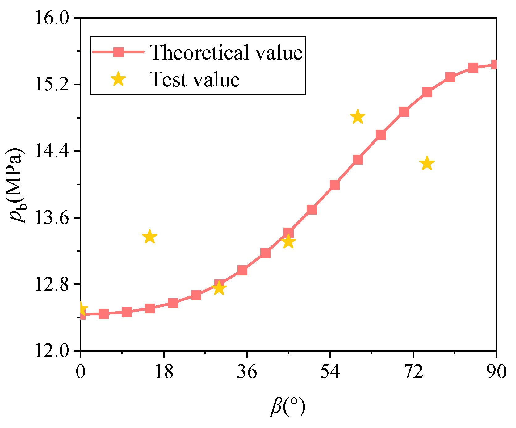
This study revealed that under conditions where the water pressure exceeds the critical fracturing pressure (pb), the fracture angle of hydraulic fractures decreases with increasing water pressure. In such cases, the influence of the critical fracture distance on hydraulic fractures diminishes. The hydraulic fracturing indoor experiments conducted in this study utilized a constant-flow water injection method, leading to an increase in internal water pressure over time within the fractures. The specimen experiences instability at the most vulnerable point, i.e., the initiation of the pre-existing crack. Therefore, considering the fracture pressure at this moment as the critical fracturing pressure, it is justified. When β = 0°, the specimen undergoes a pure Mode I fracture, and the Mode I stress intensity factor is equivalent to the pure Mode I fracture toughness. By substituting the experimental parameters into Equation (23), the theoretical prediction for the critical fracturing pressure (pb) is calculated. Comparing the experimental fracturing pressure values with the theoretical predictions, as shown in Figure 15, it can be observed that the derived formula for critical fracturing pressure performs well in predicting the hydraulic fracturing pressure for β = 0°, 30°, and 45°. However, due to the heterogeneity of rocks, some experimental data points exhibit deviations from the predicted values.
6. Conclusions
Based on the GMTS criterion, the I–II composite stress intensity factor and the critical fracture pressure of hydraulic fracture under splitting load are predicted, respectively. The theoretical formula is verified by the corresponding CSTBD specimen splitting test and true triaxial hydraulic fracturing test. The conclusions are as follows:
- (1)
- T stress affects the I–II fracture characteristics of hard rock. Based on the GMTS criterion considering T stress, the ratio of I–II composite stress intensity factor to the pure I-type fracture toughness of rock is derived, which can be used to predict I–II composite stress intensity factor of rock. By substituting the boundary conditions of CSTBD samples into GMTS criteria, it is found that GMTS criteria are more effective in predicting the I–II stress intensity factor of hard rock CSTBD samples.
- (2)
- In the hydraulic fracturing environment, the hydraulic fracture has an angle with the maximum horizontal principal stress, resulting in I–II composite fracture. At this time, the influence of T stress on the I–II fracture characteristics of hard rock is relatively small. In engineering practice, the pure I-type fracture toughness of hydraulic fracture is obtained, and the critical fracture pressure at different angles between hydraulic fracture and maximum horizontal principal stress can be predicted based on the traditional MTS criterion, which does not consider T stress.
Author Contributions
Conceptualization, W.W. and X.T.; Methodology, W.W. and X.T.; Software, X.T.; Validation, Z.L. and X.T.; Formal analysis, Z.L. and X.T.; Investigation, X.T.; Resources, W.W. and W.C.; Data curation, Z.L. and X.T.; Writing—original draft preparation, X.T.; Writing—review and editing, W.W. and W.C.; Visualization, Z.L. and X.T.; Supervision, W.W. and W.C.; Project administration, W.W. All authors have read and agreed to the published version of the manuscript.
Funding
This work was supported by the National Natural Science Foundation of China (52274118), the National Natural Science Foundation of China (52274194), the National Natural Science Foundation of China (52208341), and the Natural Science Foundation of Hunan Province (2023JJ40293), the Scientific Research Foundation of Hunan Provincial Education Department (22B0732), the Natural Science Foundation of Hunan Province (2023JJ40212).
Data Availability Statement
The datasets generated and/or analyzed during the current study are not publicly available due to privacy restrictions but are available from the corresponding author on reasonable request.
Conflicts of Interest
The authors declare no conflicts of interests.
References
- Janiszewski, M.; Shen, B.; Rinne, M. Simulation of the interactions between hydraulic and natural fractures using a fracture mechanics approach. J. Rock Mech. Geotech. Eng. 2019, 11, 1138–1150. [Google Scholar] [CrossRef]
- Yue, K.; Lee, H.P.; Olson, J.E.; Schultz, R.A. Apparent fracture toughness for LEFM applications in hydraulic fracture modeling. Eng. Fract. Mech. 2020, 230, 106984. [Google Scholar] [CrossRef]
- Zhang, Z.-T.; Wang, Y.-H.; Gao, W.-H.; Hu, W.; Liu, S.-K. Permanent Deformation and Its Unified Model of Coal Gangue Subgrade Filler under Traffic Cyclic Loading. Appl. Sci. 2023, 13, 4128. [Google Scholar] [CrossRef]
- Zhang, Z.-T.; Gao, W.-H.; Wang, X.; Zhang, J.Q.; Tang, X.-Y. Degradation-induced evolution of particle roundness and its effect on the shear behaviour of railway ballast. Transp. Geotech. 2020, 24, 100388. [Google Scholar] [CrossRef]
- Xiong, D.; Ma, X. Influence of natural fractures on hydraulic fracture propagation behavior. Eng. Fract. Mech. 2022, 276, 108932. [Google Scholar] [CrossRef]
- González-Velázquez, J.L. A Practical Approach to Fracture Mechanics; Elsevier: Amsterdam, The Netherlands, 2021; pp. 35–74. [Google Scholar] [CrossRef]
- Erdoga, F. On the Crack Extension in Plates under Plane Loading and Transverse Shear. J. Basic Eng. 1963, 85, 519–525. [Google Scholar] [CrossRef]
- Sih, G.C. Some basic problems in fracture mechanics and new concepts. Eng. Fract. Mech. 1973, 5, 365–377. [Google Scholar] [CrossRef]
- Nuismer, R.J. An energy release rate criterion for mixed mode fracture. Int. J. Fract. 1975, 11, 245–250. [Google Scholar] [CrossRef]
- Tang, S.B. The effect of T-stress on the fracture of brittle rock under compression. Int. J. Rock Mech. Min. Sci. 2015, 79, 86–98. [Google Scholar] [CrossRef]
- Mirsayar, M.M.; Razmi, A.; Aliha, M.R.M.; Berto, F. EMTSN criterion for evaluating mixed mode I/II crack propagation in rock materials. Eng. Fract. Mech. 2018, 190, 186–197. [Google Scholar] [CrossRef]
- Matvienko, Y.G. The Effect of the Non-singular T-stress Components on Crack Tip Plastic Zone under Mode I Loading. Procedia Mater. Sci. 2014, 3, 141–146. [Google Scholar] [CrossRef]
- Andrade, H.C.; Trevelyan, J.; Leonel, E.D. Direct evaluation of stress intensity factors and T-stress for bimaterial interface cracks using the extended isogeometric boundary element method. Theor. Appl. Fract. Mech. 2023, 127, 104091. [Google Scholar] [CrossRef]
- Esmaeili, A.; Mohammadi, B.; Yousefi, A. Investigation of T-stress and tensile strength effect on crack tip conditions and crack initiation angle in off-axis laminate composite. Theor. Appl. Fract. Mech. 2024, 130, 104283. [Google Scholar] [CrossRef]
- Tutluoglu, L.; Batan, C.K.; Aliha, M.R.M. Tensile mode fracture toughness experiments on andesite rock using disc and semi-disc bend geometries with varying loading spans. Theor. Appl. Fract. Mech. 2022, 199, 103325. [Google Scholar] [CrossRef]
- Williams, J.G.; Ewing, P.D. Fracture under complex stress—The angled crack problem. Int. J. Fract. 1972, 8, 441–446. [Google Scholar] [CrossRef]
- Smith, D.J.; Ayatollahi, M.R.; Pavier, M.J. The role of T-stress in brittle fracture for linear elastic materials under mixed-mode loading. Fatigue Fract. Eng. Mater. Struct. 2008, 24, 137–150. [Google Scholar] [CrossRef]
- Ayatollahi, M.R.; Moghaddam, M.; Berto, F. A generalized strain energy density criterion for mixed mode fracture analysis in brittle and quasi-brittle materials. Theor. Appl. Fract. Mech. 2015, 79, 70–76. [Google Scholar] [CrossRef]
- Ayatollahi, M.R.; Razavi, S.M.J.; Rashidi Moghaddam, M.; Berto, F. Mode I Fracture Analysis of Polymethylmetacrylate Using Modified Energy-Based Models. Phys. Mesomech. 2015, 18, 326–336. [Google Scholar] [CrossRef]
- Huang, X. Combined effects of in-plane and out-of-plane constraints on fracture behaviors in central-cracked stiffened plates: A model based on plastic zone size. Eng. Fract. Mech. 2021, 255, 107958. [Google Scholar] [CrossRef]
- Zhu, Q.; Li, D.; Ma, J.; Han, Z.; Li, X. Mixed mode I/II fracture behavior and surface morphology of hard rock under dynamic loading. Theor. Appl. Fract. Mech. 2023, 125, 103860. [Google Scholar] [CrossRef]
- Li, J.; Hua, W.; Tang, H.; Huang, J.; Dong, S. Stress intensity factors and T-stress for an edge cracked Brazilian disk specimen under diametrically distributed load. Theor. Appl. Fract. Mech. 2022, 120, 103402. [Google Scholar] [CrossRef]
- Shen, Z.; Yu, H.; Guo, L.; Hao, L.; Huang, K. A modified G criterion considering T-stress and differentiating the separation and shear failure in crack propagation. Int. J. Solids Struct. 2022, 236–237, 111357. [Google Scholar] [CrossRef]
- Tang, X.; Wan, W.; Chen, W.; Zhang, Z. Analysis of Fracture Characteristics of Ore Rock Based on GMTS Criterion. KSCE J. Civ. Eng. 2023, 27, 4352–4361. [Google Scholar] [CrossRef]
- Luo, Z.; Zhang, N.; Zhao, L.; Yao, L.; Liu, F. Seepage-stress coupling mechanism for intersections between hydraulic fractures and natural fractures. J. Pet. Sci. Eng. 2018, 171, 37–47. [Google Scholar] [CrossRef]
- Song, M.; Li, Q.; Hu, Q.; Wu, Y.; Ni, G.; Xu, Y.; Zhang, Y.; Hu, L.; Shi, J.; Liu, J.; et al. Resistivity response of coal under hydraulic fracturing with different injection rates: A laboratory study. Int. J. Min. Sci. Technol. 2022, 32, 807–819. [Google Scholar] [CrossRef]
- Suo, Y.; Dong, M.; Wang, Z.; Gao, J.; Fu, X.; Pan, Z.; Xie, K.; Qi, T.; Wang, G. Characteristics of mixed-mode I–II fracture of bedding mud shale based on discrete element method. J. Pet. Sci. Eng. 2022, 219, 111135. [Google Scholar] [CrossRef]
- Tada, H.; Paris, P.C.; Irwin, G.R. The Stress Analysis of Cracks; ASME Press: New York, NY, USA, 2000; p. 291. [Google Scholar]
- Papanastasiou, P. An efficient algorithm for propagating fluid-driven fractures. Comput. Mech. 1999, 24, 258–267. [Google Scholar] [CrossRef]
- Li, X.; Liang, Y.; Luo, Y.; Ai, C. Predicting hydraulic fracture propagation based on maximum energy release rate theory with consideration of T-stress. Fuel 2020, 269, 117337. [Google Scholar] [CrossRef]
- Rahman, M.K.; Hossain, M.M.; Rahman, S.S. An analytical method for mixed-mode propagation of pressurized fractures in remotely compressed rocks. Int. J. Fract. 2000, 103, 243–258. [Google Scholar] [CrossRef]
- Fan, Y.; Zhu, Z.; Zhao, Y.; Zhou, C.; Zhang, X. Theoretical research on formation fracture pressure and initiation Angle based on wellbore perforation model. J. Cent. South Univ. 2019, 50, 669–678. [Google Scholar] [CrossRef]
- Zhang, Z.T.; Gao, W.H. Effect of different test methods on the disintegration behaviour of soft rock and the evolution model of disintegration breakage under cyclic wetting and drying. Eng. Geol. 2020, 279, 105888. [Google Scholar] [CrossRef]
- Zhang, Z.T.; Gao, W.H.; Zeng, C.F.; Tang, X.Y.; Wu, J. Evolution of the disintegration breakage of red-bed soft rock using a logistic regression model. Transp. Geotech. 2020, 24, 100382. [Google Scholar] [CrossRef]
- Schultz, R.A. Growth of geologic fractures into large-strain populations: Review of nomenclature, subcritical crack growth, and some implications for rock engineering. Int. J. Rock Mech. Min. Sci. 2000, 37, 403–411. [Google Scholar] [CrossRef]
- Ke, C.C.; Chen, C.S.; Tu, C.H. Determination of Fracture Toughness of Anisotropic Rocks by Boundary Element Method. Rock Mech. Rock Eng. 2008, 41, 509–538. [Google Scholar] [CrossRef]
- Dong, W.; Yang, D.; Zhang, B.; Wu, Z. Rock-concrete interfacial crack propagation under mixed mode I–II fracture. J. Eng. Mech. 2018, 144, 04018039. [Google Scholar] [CrossRef]
- Zhao, Y.; Zhang, L.; Wang, Y.; Lin, H. Thermal-Hydraulic-Mechanical (THM) Coupling Behaviour of Fractured Rock Masses. Geofluids 2023, 2023, 9764934. [Google Scholar] [CrossRef]
- Ingraffea, A.R. 3—Theory of Crack Initiation and Propagation in Rock. In Fracture Mechanics of Rock; Academic Press: Cambridge, MA, USA, 1987; pp. 71–110. [Google Scholar] [CrossRef]
- Jin, P.; Liu, Z.; Wang, X.; Chen, X. Three-Dimensional analysis of mixed mode Compact-Tension-Shear (CTS) Specimens: Stress intensity Factors, T-stresses and crack initiation angles. Theor. Appl. Fract. Mech. 2022, 118, 103218. [Google Scholar] [CrossRef]
- Wang, C.; Wang, S. Modified generalized maximum tangential stress criterion for simulation of crack propagation and its application in discontinuous deformation analysis. Eng. Fract. Mech. 2022, 259, 108159. [Google Scholar] [CrossRef]
- Mroz, K.P. Fatigue Cracks Growth in the Bimaterial System, The Mathematical Model and Numerical Solution; IPPTPAN (IFTRPAS): Warsaw, Poland, 2008. (In Polish) [Google Scholar]
- Yin, T.; Wu, Y.; Wang, C.; Zhuang, D.; Wu, B. Mixed-mode I + II tensile fracture analysis of thermally treated granite using straight-through notch Brazilian disc specimens. Eng. Fract. Mech. 2020, 234, 107–111. [Google Scholar] [CrossRef]
- Zhou, Z.; Yang, H.; Wang, X.C.; Zhang, Q.F. Fractured rock mass hydraulic fracturing under hydrodynamic and hydrostatic pressure joint action. J. Cent. South Univ. 2016, 23, 2695–2704. [Google Scholar] [CrossRef]
- He, H.; Cheng, R.; Zhao, J.; Men, Z.; Mu, Z. Research on the initiation pressure criterion of directional hydraulic fracturing in coal mine. Heliyon 2023, 9, e17638. [Google Scholar] [CrossRef] [PubMed]
- Ye, H.; Yang, L.; Liu, Z.; Deng, Q. Study on acoustic emission response characteristics of sandstone in directional fracturing under different filtration surfaces. Saf. Coal Mine 2022, 53, 62–67. [Google Scholar] [CrossRef]
Figure 1.
Stress diagram of the central straight-crack Brazilian disk specimen.
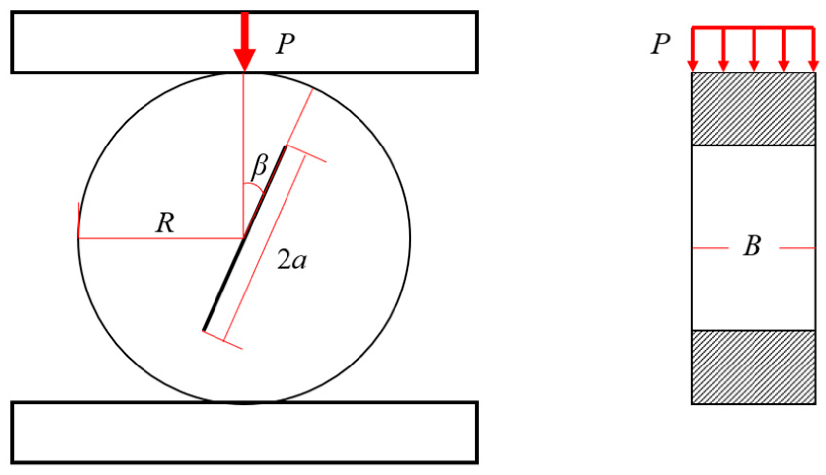
Figure 2.
Load–displacement curve of the CSTBD specimen in the splitting test.

Figure 3.
Failure of the specimen.

Figure 4.
The effect of T stress on the fracture angle of the CSTBD splitting test.
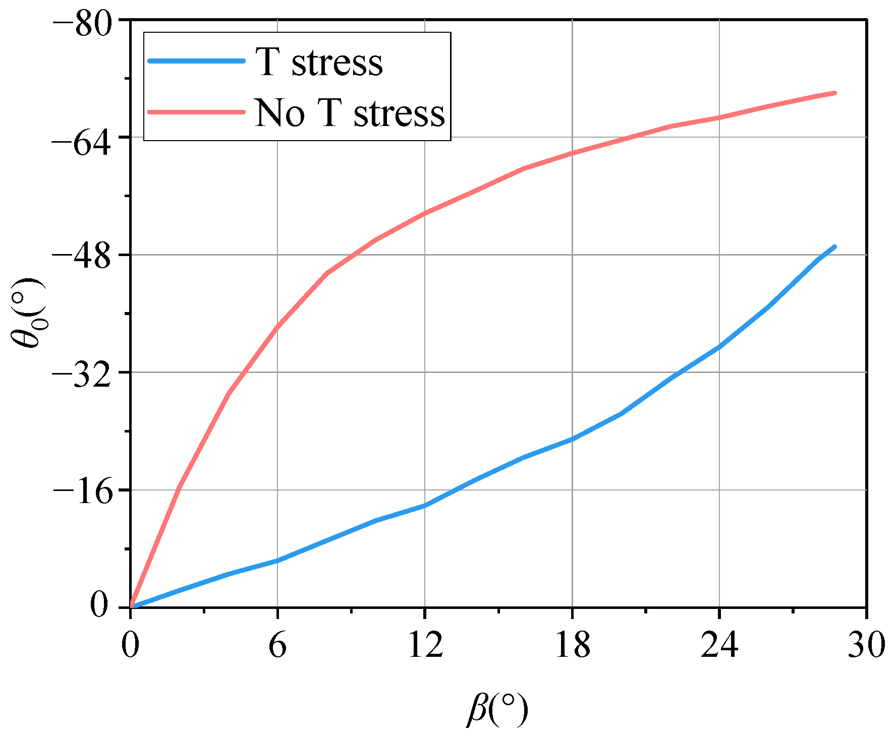
Figure 5.
Effect of T stress on the fracture toughness of the CSTBD splitting test crack.
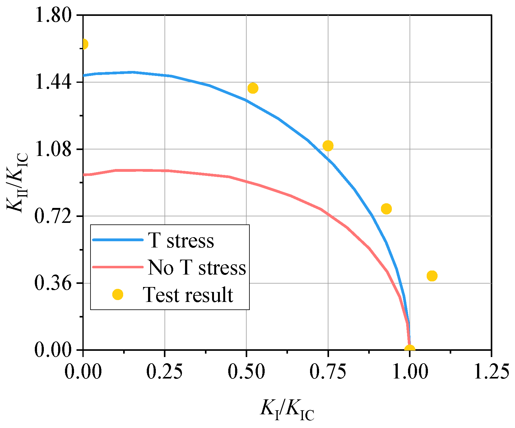
Figure 6.
Principle of the superposition of stress. (a) Fracture mechanics model; (b) σH and σh controls; and (c) pw controls.
Figure 6.
Principle of the superposition of stress. (a) Fracture mechanics model; (b) σH and σh controls; and (c) pw controls.
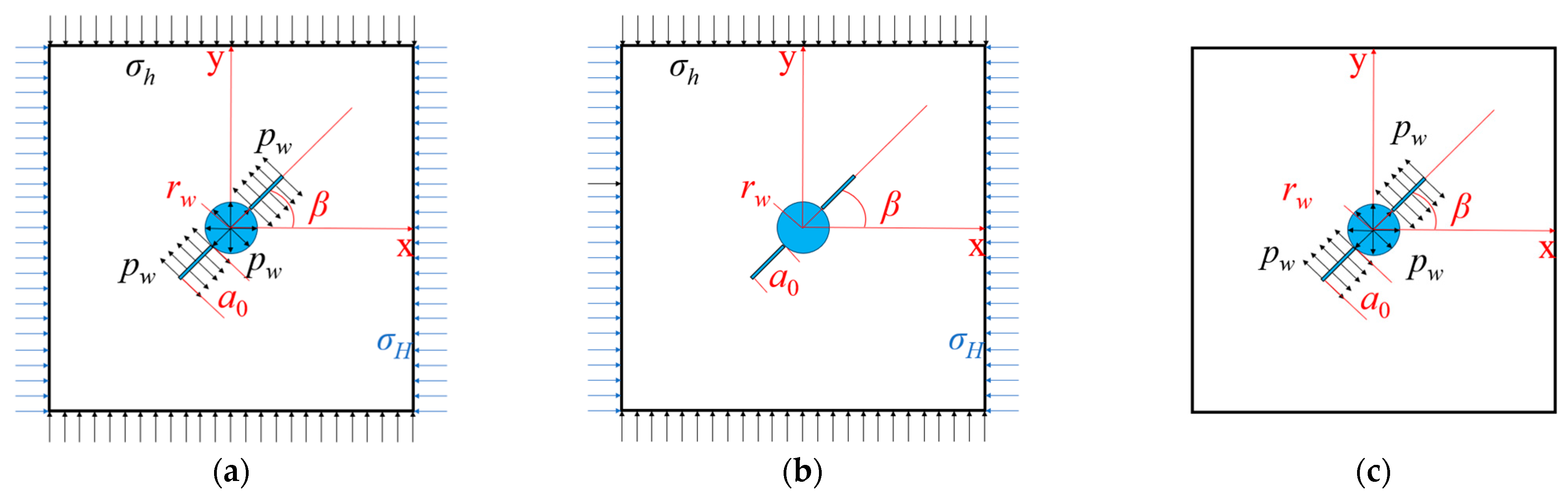
Figure 7.
Principle of conformal mapping.
Figure 8.
Fracture pressure calculation flowchart.
Figure 9.
Influence of T stress on the pb and θc of hard rock. (a) rc = 0.08 mm; (b) rc = 1 mm.
Figure 11.
Specimen sealing method.
Figure 12.
True triaxial hydraulic fracturing test system.

Figure 13.
Pumping pressure time history curve.

Figure 14.
Morphologies of hydraulic fractures.
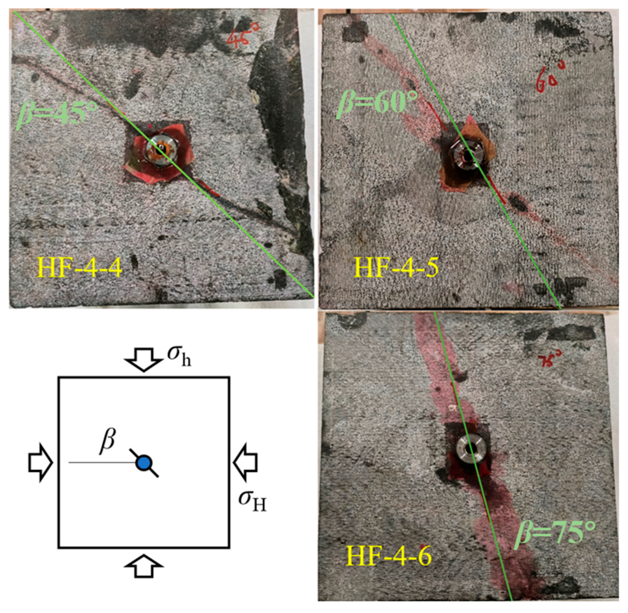
Figure 15.
Comparison between the theoretical and experimental values of pb.

Table 1.
Basic physical and mechanical parameters.
| Parameter | Value |
|---|---|
| Cohesive force c | 24.44 MPa |
| Internal friction angle of rock φ | 40.77° |
| Compressive strength σp | 155.81~210 MPa |
| Tensile strength σt | 7.5~13.5 MPa |
| Modulus of elasticity E | 82.3~92.5 GPa |
| Poisson’s ratio v | 0.17~0.3 |
Table 2.
KI, KII, and T values of different β specimens.
| β (°) | KI (MPa·m1/2) | KII (MPa·m1/2) | T (MPa) |
|---|---|---|---|
| 0 | 0.5498 | 0 | −17.5319 |
| 5 | 0.5873 | 0.2192 | −19.0127 |
| 10 | 0.5106 | 0.4175 | −17.3881 |
| 15 | 0.4124 | 0.6038 | −15.6009 |
| 20 | 0.2858 | 0.7739 | −13.4206 |
| 28.7 | ≈0 | 0.9040 | −7.7515 |
Table 3.
Hydraulic fracturing test scheme.
| ID | σz (MPa) | σH (MPa) | σh (MPa) | Injection Rate (mL/min) | β (°) |
|---|---|---|---|---|---|
| HF-1 | 12 | 9 | 6 | 20 | 0 |
| HF-2 | 12 | 9 | 6 | 20 | 15 |
| HF-3 | 12 | 9 | 6 | 20 | 30 |
| HF-4 | 12 | 9 | 6 | 20 | 45 |
| HF-5 | 12 | 9 | 6 | 20 | 60 |
| HF-6 | 12 | 9 | 6 | 20 | 75 |
| HF-7 | 12 | 9 | 6 | 20 | 90 |
Disclaimer/Publisher’s Note: The statements, opinions and data contained in all publications are solely those of the individual author(s) and contributor(s) and not of MDPI and/or the editor(s). MDPI and/or the editor(s) disclaim responsibility for any injury to people or property resulting from any ideas, methods, instructions or products referred to in the content. |
© 2024 by the authors. Licensee MDPI, Basel, Switzerland. This article is an open access article distributed under the terms and conditions of the Creative Commons Attribution (CC BY) license (https://creativecommons.org/licenses/by/4.0/).
Share and Cite
MDPI and ACS Style
Tang, X.; Wan, W.; Lu, Z.; Chen, W. Study on Composite Fracture Characteristics and Hydraulic Fracturing Behavior of Hard Rock. Appl. Sci. 2024, 14, 2585. https://doi.org/10.3390/app14062585
AMA Style
Tang X, Wan W, Lu Z, Chen W. Study on Composite Fracture Characteristics and Hydraulic Fracturing Behavior of Hard Rock. Applied Sciences. 2024; 14(6):2585. https://doi.org/10.3390/app14062585
Chicago/Turabian StyleTang, Xiaoyu, Wen Wan, Zhenxing Lu, and Wei Chen. 2024. "Study on Composite Fracture Characteristics and Hydraulic Fracturing Behavior of Hard Rock" Applied Sciences 14, no. 6: 2585. https://doi.org/10.3390/app14062585
Note that from the first issue of 2016, this journal uses article numbers instead of page numbers. See further details here.