
Long-Range Imaging LiDAR with Multiple Denoising Technologies
by
 ,
,
Huaibin Zheng
1,*,
Yuyuan Han
1,
Long Qiu
1,
Yanfeng Zong
1,
Jingwei Li
1,
Yu Zhou
2,
Yuchen He
1,
Jianbin Liu
1,
Gao Wang
1,
Hui Chen
1 and
Zhuo Xu
1 1
Electronic Materials Research Laboratory, Key Laboratory of the Ministry of Education and International Center for Dielectric Research, School of Electronic and Information Engineering, Xi’an Jiaotong University, Xi’an 710049, China
2
MOE Key Laboratory for Nonequilibrium Synthesis and Modulation of Condensed Matter, Department of Applied Physics, Xi’an Jiaotong University, Xi’an 710049, China
*
Author to whom correspondence should be addressed.
Appl. Sci. 2024, 14(8), 3414; https://doi.org/10.3390/app14083414
Submission received: 8 February 2024
/
Revised: 14 April 2024
/
Accepted: 15 April 2024
/
Published: 18 April 2024
(This article belongs to the Section Optics and Lasers)
Abstract
:The ability to capture and record high-resolution images over long distances is essential for a wide range of applications, including connected and autonomous vehicles, defense and security operations, as well as agriculture and mining industries. Here, we demonstrate a self-assembled bistatic long-range imaging LiDAR system. Importantly, to achieve high signal-to-noise ratio (SNR) data, we employed a comprehensive suite of denoising methods including temporal, spatial, spectral, and polarization filtering. With the aid of these denoising technologies, our system has been validated to possess the capability of imaging under various complex usage conditions. In terms of distance performance, the test results achieved ranges of over 4000 m during daylight with clear weather, 19,200 m at night, 6700 m during daylight with haze, and 2000 m during daylight with rain. Additionally, it offers an angular resolution of 0.01 mrad. These findings demonstrate the potential to offer comprehensive construction strategies and operational methodologies to individuals seeking long-range LiDAR data.
1. Introduction
Active optical imaging has a wide range of applications, such as remote sensing [1], airborne surveillance [2], target recognition [3], augmented reality [4], navigation [5], landing [6], and so on. Among the proposed methods for imaging measurement, LiDAR exhibits exceptional potential for long-range and real-time applications. These capabilities surpass alternative techniques such as stereo-vision [7] and structured-light [8], which are typically constrained to shorter ranges.
Regarding the full-scale range [9], LiDAR [10] systems can be categorized into short range (up to a few meters, e.g., in augmented reality for gaming), medium range (up to a few tens of meters, e.g., in industrial automation), and long range (hundreds of meters or kilometers, e.g., automotive and satellite vision). Achieving long ranges requires pulsed-LiDAR techniques combined with high-power lasers, detectors with high sensitivity, and timing electronics with sufficient full-scale range. However, implementing and applying this technology for outdoor applications face challenges due to various interfering factors, such as strong solar background illumination and inclement weather conditions such as rain and fog. To overcome these challenges, denoising technologies, including temporal filtering [11], spatial filtering [12], spectral filtering [13], polarization filtering [14], etc., have been developed. Depending on the requirements of different application scenarios, one or multiple technologies are selected.
When reconstructing two- or three-dimensional (2D and 3D) scenes using LiDAR, scanning is crucial [15,16]. This can be achieved by utilizing optomechanical elements [17] (such as rotating mirrors and prisms), electromechanical moving parts (such as electric motors with mechanical stages), or compact micro electro-mechanical system (MEMS) mirrors [18] and solid-state optical phase arrays (OPAs) [19]. The selection of the scanning scheme necessitates careful consideration of multiple parameters, including laser energy, repetition frequency, eye-safety thresholds, detector architecture, measurement speed, and system complexity. For instance, MEMS and OPAs offer a more compact and lightweight alternative to electromechanical scanning while also enabling faster scanning through the utilization of resonant mirrors. It is important to note that each technology has its own limitations; therefore, there is no universally preferred option for all applications. In this work, focusing on long-range imaging LiDAR systems (exceeding ten kilometers with high-power lasers), the scanning mechanism adopts optomechanical elements.
Array-based imaging utilizing single photon avalanche diodes (SPADs) presents a relatively accessible technology, as evidenced by numerous research reports. For instance, Ren et al. showcased laser ranging up to 32 m utilizing a 1 GHz sine-wave InGaAs/InP SPAD [20]. Other studies demonstrated sub-centimeter resolution ranging at a standoff distance of 330 m using superconducting niobium nitride nanowire single-photon detectors [21], and centimeter resolution depth imaging with low signature objects at distances up to 1 km employing an InGaAs/InP SPAD [22]. A study employing a 32 × 32 InGaAs/InP Geiger-mode array demonstrated three-dimensional imaging over ranges extending to 9 km [23,24]. Moreover, Li et al. provided an experimental demonstration of long-range 3D imaging surpassing 200 km [25]. Nonetheless, achieving high-resolution imaging at kilometer-scale distances introduces formidable challenges, primarily the dearth of signal photons and the significant solar background illumination. Traditional long range LiDAR imaging systems that rely on SPAD array detectors for single photon operations are not only costly but also largely experimental. This dependence frequently precipitates a precipitous decrease in the signal-to-background ratio (SBR) as the imaging distance increases, thereby constraining the effectiveness of image reconstruction [26].
For researchers in this field, regardless of the type of LiDAR system, achieving reliable performance in complex practical application environments poses a formidable challenge. In this paper, we present a self-assembled bistatic long-range imaging LiDAR system and elucidate its operational mechanism. Firstly, the acquisition of data with high SNR is the prerequisite to ensure the normal operation of the system. Therefore, a comprehensive suite of denoising techniques was employed to the LiDAR, including temporal, spatial, spectral, and polarization filtering methods. To validate its performance, intensity imaging experiments were conducted under bright day, night-time, and hazy conditions as well as during rainfall, demonstrating current system possess the capability of imaging under various complex usage conditions. Meanwhile, the integration of the compressive sensing [27] algorithm enables robust reconstruction of images even when the data is deeply embedded within low samples. The experimental results demonstrate that the system exhibits high spatial resolution and robust anti-interference capabilities. Consequently, this methodically constructed system can provide readers with reliable LiDAR data for subsequent image application research.
2. Methods
2.1. Description of the Time-Gated Long-Range Imaging LiDAR System
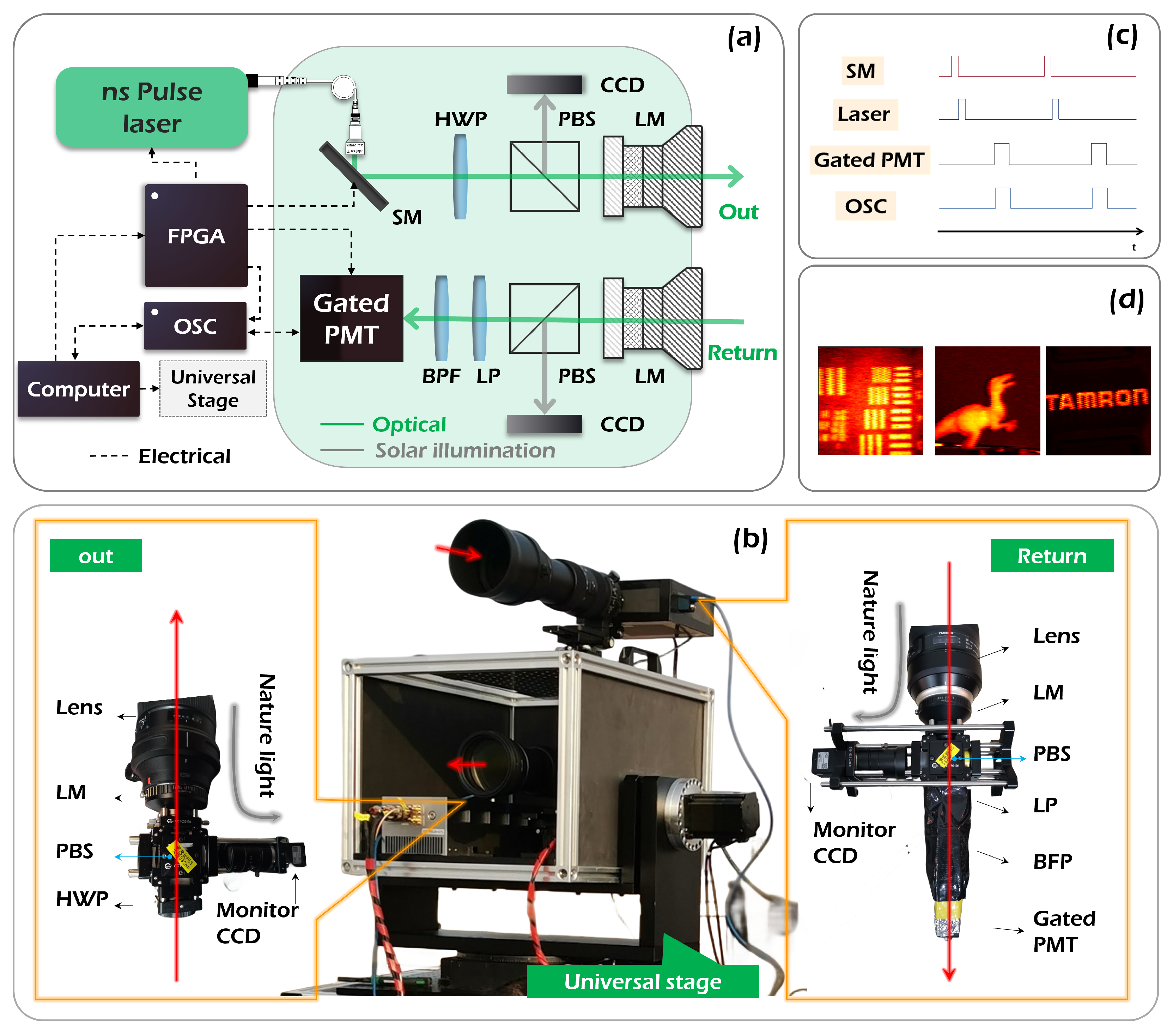
The time-gated long-range imaging LiDAR system is configured in a bistatic setup comprising three parts: the transmitter, the receiver, and the associated system control components, as shown in Figure 1a,b. A 532 nm wavelength pulsed laser illumination was provided by a medium repetition frequency nanosecond pulsed all-solid-state laser (AOML-500, Nanjing Institute of Advanced Laser Technology, Nanjing, China). For the measurement reported here, the repetition frequency of the laser was set to 10 kHz and the illumination beam had a maximum average optical power of 1.7 W on exiting the laser head, corresponding to approximately 170 μJ per pulse. The pulse width of the laser was 6.4 ns. This selected output was used on a pair of scanning mirrors (SM with 10 kHz), passed through a half-wave plate (HWP), a polarizing beam splitter (PBS), and relay optics, and exited the transmitter head through the camera lens objective (SIGMA 150–600 mm S version, Sigma Corporation, Kawasaki, Japan).The probe laser was scanned across the scene of interest by a galvano mirror pair. In addition, 50% of the incoming natural light from the transmitter head is reflected into a monitoring channel (CCD in the transmitting light path as shown in the left panel of Figure 1b). Its primary function is to assist the LiDAR equipment in delineating the illuminated area, compensating for the limited long-distance observation capabilities of human eyes.
As shown in the right panel of Figure 1b, the scattered optical return from the distant target went through the same receiver lens (SIGMA 150–600 mm S version, Sigma Corporation, Kawasaki, Japan) and relay optics, passed through the polarizing beam splitter (PBS), a linear polarizer (LP), and a narrow bandpass filter (1.2 nm@ 532 nm), and coupled into a gated photomultiplier tube (gated-PMT, H11526-20NF, Hamamatsu Photonics K.K., Hamamatsu, Japan). Similarly, 50% of the incoming natural light from the receiver head is reflected into another monitoring channel. The polarization beam splitter and the linear polarizer were used to orientate the polarization in order to suppress the solar background illumination. Such a bistatic system can effectively suppress the noise caused by optical back reflections from the components.
The associated system control unit for the pulsed laser source, scanning mirrors, the gated-PMT detector, the acquisition module, and the universal stage was needed for sequence control, as shown in Figure 1c, realized by a Field Programmable Gate Array (FPGA) device. Moreover, the system can gain further noise reduction benefits from such a design. The sequence control logic is demonstrated in Figure 2. Firstly, calibrate the universal stage with the help of the monitoring channel and then standby. Then, instruct the scanner to move to the designated position and remain on standby. Subsequently, generate a specific quantity of laser pulses. Next, simultaneously activate the gated-PMT detector and the acquisition module after a designated duration of time, with the option to adjust the gate opening time based on the system’s distance from the objective. In this step, one can adjust the gate width for the acquisitions to optimize the signal to noise (SNR). Finally, apply data preprocessing. After completing this operation, proceed to the subsequent operations in a sequential manner until the entire scene is comprehensively scanned. By means of relative algorithms, one can reconstruct the image. Initial validation results, displaying high-resolution, low-noise indoor imaging at 20 m, are presented in Figure 1d. These imaging targets are, a 1951 USAF resolution, a 5 cm tall dinosaur toy and a 10 cm diameter lens cap with the company name (TAMRON) on it, respectively.
The acquisition of data with high SNR is the prerequisite to ensure the normal operation of the system. Therefore, a comprehensive suite of denoising techniques was applied to the current LiDAR system, encompassing temporal, spatial, spectral, and polarization filtering methods, as shown in the probe part of Figure 1a. In detail, the polarization filter works first with the help of polarization beam splitter, where 50% of the solar background illumination from the receiver head is filtered and most of the signal light can get through. Then, the spectral filter works by a narrow bandpass filter (1.2–532 nm), where the solar background illumination outside the 1.2 nm bandwidth is removed. Finally, the temporal filter is used with the range-gated technique. In addition, the spatial filter works using telephoto lenses with a small field of view. With the help of these noise reduction techniques, the noise is reduced to about ten million parts of the original noise.
It is worth noting that both lenses can be adjusted to meet different requirements. As depicted in Table 1, the first row presents an imaging result of a building located at a distance of 2500 m using the aforementioned setup, while the second row displays the same building captured with another transmitter lens featuring a focal length of 2000 mm and an aperture diameter of 200 mm. Evidently, the result in the second row exhibit higher resolution, revealing more intricate details of windows. Typically, a larger aperture corresponds to a higher resolution, but also entails a smaller field of view and longer distance.
2.2. PMT-Based Time-Gated Measurement
The system utilizes a pulsed nanosecond light source and operates the PMT detector in gated mode to perform time-gated imaging. Upon emission of a laser pulse, the PMT is triggered to acquire data for the corresponding duration determined by gating. By introducing a temporal delay to synchronize the return light signal with the electronic gate of the detector, we enable imaging of light returning from a predetermined range. In this context, it is important to note that the PMT serves as an intensity sensor capable of reconstructing images with varying grayscale intensities.
2.3. Data Acquisition
The detector’s time-gating capability allows for the segmentation of the target scene. Specifically, a gate width of 50 ns is employed to capture all incoming light that arrives within this temporal delay. With its rapid rise time, objects can be clearly distinguished as they enter and exit the captured signal, depending on the positioning of the gate. In other words, by strategically delaying the gate, returning light from certain objects can be detected within the imaging gate, while light from other objects outside of this range is effectively rejected. This significantly enhances the system’s signal-to-noise ratio (SNR).
To obtain 3D information about a target, it is necessary to temporally scan the gate across the object and accurately measure the precise time at which the object enters the gate. This measured time can then be converted into distance. Furthermore, it should be noted that the fixed repetition rate of the laser used in this study was significantly lower [28], at 10 KHz, resulting in a pulse separation of 30,000 m and a maximum stand-off distance free from range ambiguity of 15,000 m. As such, any potential range ambiguity can be considered negligible for this experiment.
2.4. Image Reconstruction
Compressive Sensing (CS) is a mathematical technique that has been widely adopted for intelligent and efficient sampling and storage, enabling sparse representations. Initially proposed to overcome the limitations of conventional signal processing that relied on Nyquist sampling requirements, CS is based on the concept of obtaining observations by computing the inner product between the signal and an observation function, and then recovering the signal from linear observations using a highly nonlinear optimization problem. Unlike traditional imaging methods, CS imaging can acquire high-quality images from a lower sampling rate than the Nyquist sampling rate, thereby reducing the number of sensors and hardware costs [29]. However, solving the inverse problem in CS requires iterative linear programming solvers to optimize the problem. It can be written as:
where delineates N-dimensional real signals and the retrieval of x from y presents a conundrum of solving a system of linear equations. In this context, the expansion factor may be presumed to exhibit k-sparsity, thereby signifying that the quantity of nonzero coefficients, denoted as k, markedly diminishes in comparison to the dimensionality N of the signals. Furthermore, the introduction of an observation matrix , conventionally a Gaussian matrix, assumes prominence. Remarkably, operates autonomously from the orthogonal base dictionary , with its interaction confined solely to the coefficients. This enables the capture of a fraction of the signal’s information. In scenarios where the coefficients manifest sparsity, thereby substantially curtailing the number of unknowns, the reconstruction of the signal is viable even at sampling rates lower than the Nyquist sampling rate. Table 2 depicts the imaging results of compressive sensing correlation imaging at various sampling rates. The imaging target is a tower crane at a construction site located 4000 m away, under imaging conditions of 5:00 PM in the afternoon with clear weather, showcasing the resilience of CS in image reconstruction even at remarkably low sampling rates, such as 5% and 10% (original sampling rate of 3000). However, lower sampling rates result in the loss of some fine details. In the context of compressive sensing algorithms, it has been observed that at a sampling rate of 20%, the basic outlines of the signal can still be discerned. Here, we focus solely on compressive sensing without further elaboration. Sampling rates above 20% ensure the acquisition of essential signal features, satisfying the requirements of imaging detection. This significantly reduces the time required for imaging detection.
3. Results and Discussion
We conducted a series of field trials under diverse environmental conditions (including night, bright daylight, rainy, and hazy weather) to investigate the acquisition of intensity images from scenes containing various typical noncooperative materials, such as buildings, metal, paint, etc. The LiDAR system was deployed on the rooftop for short-range measurements and on the Qinling Mountains (near Xi’an city, China) for long-range measurements exceeding 9000 m distance. Considering the potential risk to human ocular safety posed by the nonsafe wavelength of the 532 nm laser, we prioritized experimental safety, and consequently, directed our imaging efforts towards roofs and elevated structures. In addition, only an intensity image (not a 3D image) at a specific depth was reconstructed in the following tests.
3.1. Imaging on a Hazy Day
As is well known, the presence of disturbances on the transmission path, such as clouds, rain, and haze, poses significant challenges to the effectiveness of optical imaging. Starting from 4 p.m. in the winter, we conducted intensity imaging measurements of a haze scene with a PM 2.5 particle concentration of 167 μg/ based on data from the China Air Quality Index. The utilization of gating technology and polarization filtering technology enables this system to achieve imaging detection beyond the line-of-sight, as shown in Figure 3. The roof platform of a structure was captured at an approximate distance of 870 m, utilizing a resolution of 128 × 128 pixels. Subsequently, the logo of a building was imaged at a distance of around 4665 m, again at the same resolution. Additional objects, i.e., a building and a TV tower, were imaged at distances of roughly 6000 m and 6570 m, respectively, both at a resolution of 128 × 128 pixels. In hazy conditions, both the incident and echo photons may be scattered by haze particles, leading to a weaker signal and stronger noise photons. This effect becomes more pronounced as the distance increases.
3.2. Imaging in Bright Daylight
Next, we performed a series of outdoor test in bright daylight. The measurements were made at stand-off distances of 150 m (microwave radar antenna), 1900 m (building baluster), 2500 m (house), and 4000 m (tower crane)—these distances correspond to accessible locations with unobstructed views from our roof laboratory facility. These distances were measured by our LiDAR system based on the time of flight (TOF) function. Given that strong solar background illumination is the primary source of noise, effective denoising capabilities are crucial. Current LiDAR system employs a combination of temporal, spatial, spectral, and polarization filtering techniques to address this issue. We conducted scans at varying distances of a microwave radar antenna, building baluster, residential structure, and tower crane. The resulting imaging outcomes are presented in Figure 4 with a reconstructed image pixel resolution of 128 × 128 and per-pixel acquisition time of 0.1 ms. The profiles and details can be clearly observed. The steel structure size of the tower crane, measuring approximately 5 cm in width, showcases a remarkable spatial resolution of the LiDAR system surpassing 5 cm at 4000 m, corresponding to an angle resolution of 0.01 mrad. The detection range is limited by sunlight interference during daytime testing, and at greater distances, the SNR decreases significantly, making image reconstruction challenging. In addition to increasing the laser power, enhancing the per-pixel acquisition time can further enhance the range. However, since the coexistence between signal and noise impedes significant enhancement of the SNR, the degree of increased distance is unsatisfactory.
3.3. Imaging at Night
Next, the measurements were made in night conditions, which can play the best performance of the LiDAR system due to the high SNR data acquisition. Here, as shown in Figure 5, we present four long-range imaging results at distances of approximately 9000 m (building), 13,000 m (TV tower head), 14,000 m (building), and 19,200 m (building). These distances correspond to locations that are accessible and offer unobstructed views from the hillside of the Qinling Mountains. Similar to the previous section, TOF is employed for measuring these distances with an image pixel resolution of 128 × 128. However, each pixel’s acquisition time is set to 1 ms. As depicted in Figure 5, the reconstructed image enables extraction of profiles and typical details. Given that the building at 19,200 m is the farthest target visible within the field of view, we contend that this system has the capability to detect even longer distances under nighttime conditions.
3.4. Imaging on a Rainy Day
UTF8gbsn A rainy day is a common scenario for imaging. Finally, we conducted intensity imaging measurements on a day with moderate rainfall through the window of our laboratory. The imaging results with a resolution of 128 × 128 pixels, including a microwave radar antenna positioned at 150 m, a clock situated atop the building at 250 m, a building under construction located at 1500 m, and an attic within the building observed at 2000 m, are depicted in Figure 6. At these distances, the profiles and details can be clearly observed. For instance, a Chinese character “中” is discernible in the lower right section of the image (refer to Figure 6c), which is part of the slogan. Moreover, the structure of the attic with the building can be clearly captured (see Figure 6d). These imaging results demonstrate that the transmitter, equipped with such a camera lens, possesses sufficient resolution. Compared to the imaging results obtained during haze weather, where particle scattering is the primary source of interference, this LiDAR system exhibits a comparable imaging capability even in rainy conditions. However, due to its indoor deployment, measurements were not taken for distant objects that were obscured.
3.5. Time Consumed by Imaging Reconstruction
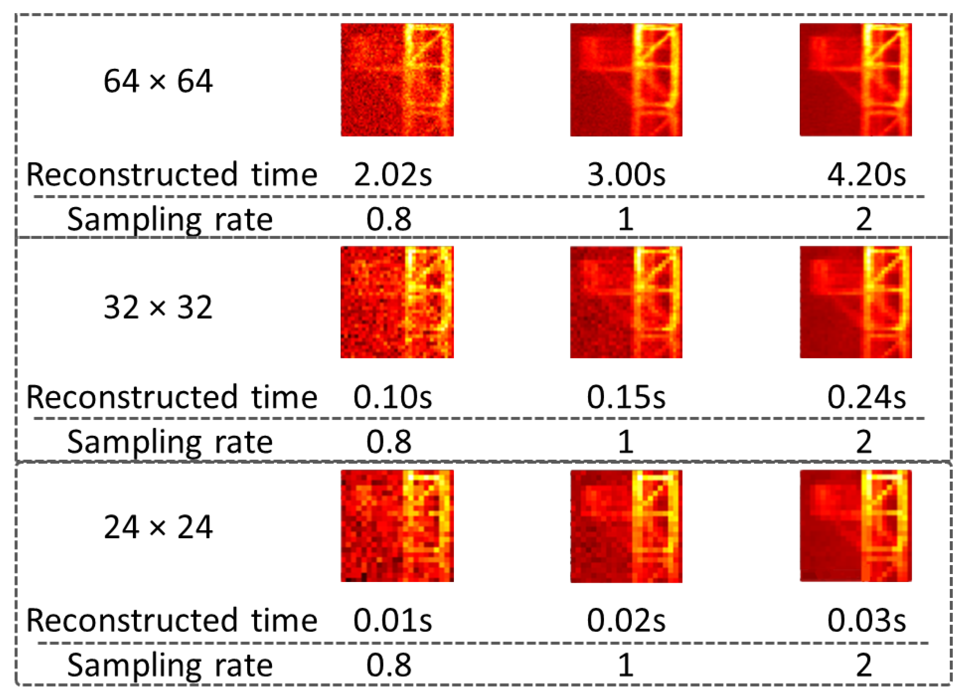
Imaging frame rates are paramount in long-range imaging LiDAR systems, particularly concerning real-time imaging capabilities. A thorough investigation into the system’s real-time imaging performance was conducted, as depicted in Figure 7, which illustrates the time consumed by imaging reconstruction across various imaging parameters, including frame rates. The experimental findings underscore the intricate correlation between imaging frame rates and sampling rates with the image resolution, alongside the computational power of the computing hardware. Remarkably, employing a standard computer setup facilitates the consistent achievement of imaging frame rates at 24 Hz across diverse sampling settings, while upholding a resolution of 24 × 24 pixels.
4. Conclusions
In conclusion, we have present a home-built bistatic pulsed-LiDAR system equipped with a gated-PMT detector, providing readers with an in-depth understanding of its operational principles for construction and utilization. To obtain high SNR data, a comprehensive suite of denoising techniques was employed, including temporal, spatial, spectral, and polarization filtering methods. The proposed system demonstrated the capability to operate effectively under various challenging conditions, including daytime and other complex scenarios, leveraging advanced denoising technologies. Especially, it possesses the capability to mitigate the impact of scattering and solar background radiation, which is the guarantee that the equipment can work properly outdoors. Regarding operational range, the system exhibited impressive capabilities, achieving distances exceeding 4000 m in clear daylight, 19,200 m under nocturnal conditions, 6700 m during hazy daytime conditions, and 2000 m amidst daylight rain. Furthermore, it boasts an angular resolution of 0.01 mrad. By applying compressive sensing algorithms, it is observed that a sampling rate of 20% was adequate for discerning basic signal outlines, thereby meeting the requirements of imaging detection, significantly reducing processing time. The findings presented herein offer valuable insights into the pragmatic realization of imaging systems with promising potential for compact construction, facilitating the acquisition of data for subsequent processing and application.
Author Contributions
Conceptualization, H.Z., H.C. and G.W.; methodology, H.Z.; software, Y.Z. (Yu Zhou); validation, Y.H. (Yuyuan Han), L.Q. and Y.Z. (Yanfeng Zong); formal analysis, J.L. (Jingwei Li); resources, Y.H. (Yuchen He); data curation, J.L. (Jianbin Li); writing—original draft preparation, Y.H. (Yuyuan Han); writing—review and editing, H.Z.; visualization, H.Z.; supervision, Z.X.; project administration, H.Z.; funding acquisition, H.Z. All authors have read and agreed to the published version of the manuscript.
Funding
This research was funded by the National Natural Science Foundation of China (62375215), Shaanxi Key Research and Development Project (Grant No. 2019ZDLGY09-10), and Shaanxi Key Research and Development Project (2019ZDLGY09-09).
Institutional Review Board Statement
Not applicable.
Informed Consent Statement
Not applicable.
Data Availability Statement
The data presented in this study are available on request from the corresponding author.
Conflicts of Interest
The authors declare no conflicts of interest.
References
- Besl, P.J. Active, optical range imaging sensors. Mach. Vis. Appl. 1988, 1, 127–152. [Google Scholar] [CrossRef]
- Shi, Z.; Yu, L.; Cao, D.; Wu, Q.; Yu, X.; Lin, G. Airborne ultraviolet imaging system for oil slick surveillance: Oil–seawater contrast, imaging concept, signal-to-noise ratio, optical design, and optomechanical model. Appl. Opt. 2015, 54, 7648–7655. [Google Scholar] [CrossRef] [PubMed]
- Zeng, R.; Wen, Y.; Zhao, W.; Liu, Y.J. View planning in robot active vision: A survey of systems, algorithms, and applications. Comput. Vis. Media 2020, 6, 225–245. [Google Scholar] [CrossRef]
- Xiong, J.; Hsiang, E.L.; He, Z.; Zhan, T.; Wu, S.T. Augmented reality and virtual reality displays: Emerging technologies and future perspectives. Light. Sci. Appl. 2021, 10, 216. [Google Scholar] [CrossRef] [PubMed]
- Dix-Matthews, B.P.; Schediwy, S.W.; Gozzard, D.R.; Savalle, E.; Esnault, F.X.; Lévèque, T.; Gravestock, C.; D’Mello, D.; Karpathakis, S.; Tobar, M.; et al. Point-to-point stabilized optical frequency transfer with active optics. Nat. Commun. 2021, 12, 515. [Google Scholar] [CrossRef] [PubMed]
- Herissé, B.; Hamel, T.; Mahony, R.; Russotto, F.X. Landing a VTOL unmanned aerial vehicle on a moving platform using optical flow. IEEE Trans. Robot. 2011, 28, 77–89. [Google Scholar] [CrossRef]
- Tippetts, B.; Lee, D.J.; Lillywhite, K.; Archibald, J. Review of stereo vision algorithms and their suitability for resource-limited systems. J.-Real-Time Image Process. 2016, 11, 5–25. [Google Scholar] [CrossRef]
- Angelsky, O.V.; Bekshaev, A.Y.; Hanson, S.G.; Zenkova, C.Y.; Mokhun, I.I.; Jun, Z. Structured light: Ideas and concepts. Front. Phys. 2020, 8, 114. [Google Scholar] [CrossRef]
- Raj, T.; Hanim Hashim, F.; Baseri Huddin, A.; Ibrahim, M.F.; Hussain, A. A survey on LiDAR scanning mechanisms. Electronics 2020, 9, 741. [Google Scholar] [CrossRef]
- Royo, S.; Ballesta-Garcia, M. An Overview of Lidar Imaging Systems for Autonomous Vehicles. Appl. Sci. 2019, 9, 4093. [Google Scholar] [CrossRef]
- Schied, C.; Peters, C.; Dachsbacher, C. Gradient estimation for real-time adaptive temporal filtering. Proc. Acm Comput. Graph. Interact. Tech. 2018, 1, 1–16. [Google Scholar] [CrossRef]
- Fan, L.; Zhang, F.; Fan, H.; Zhang, C. Brief review of image denoising techniques. Vis. Comput. Ind. Biomed. Art 2019, 2, 1–12. [Google Scholar] [CrossRef]
- Onuki, M.; Ono, S.; Yamagishi, M.; Tanaka, Y. Graph signal denoising via trilateral filter on graph spectral domain. IEEE Trans. Signal Inf. Process. Over Netw. 2016, 2, 137–148. [Google Scholar] [CrossRef]
- Abubakar, A.; Zhao, X.; Li, S.; Takruri, M.; Bastaki, E.; Bermak, A. A block-matching and 3-D filtering algorithm for Gaussian noise in DoFP polarization images. IEEE Sens. J. 2018, 18, 7429–7435. [Google Scholar] [CrossRef]
- Hu, Y.; Hou, A.; Zhang, X.; Han, F.; Zhao, N.; Xu, S.; Ma, Q.; Gu, Y.; Dong, X.; Chen, Y.; et al. Assessment of Lateral Structural Details of Targets using Principles of Full-Waveform Light Detection and Ranging. IEEE Trans. Geosci. Remote Sens. 2023, 61, 1–16. [Google Scholar] [CrossRef]
- Hu, Y.; Zhang, X.; Hou, A.; Xu, S.; Gu, Y.; Lu, H.; Ma, Q.; Zhao, N.; Fang, J. Laser echo waveform modulation modelling from lateral structure using a mathematical formula. Int. J. Remote Sens. 2023, 44, 2382–2399. [Google Scholar] [CrossRef]
- Wang, D.; Watkins, C.; Xie, H. MEMS mirrors for LiDAR: A review. Micromachines 2020, 11, 456. [Google Scholar] [CrossRef] [PubMed]
- Poulton, C.V.; Yaacobi, A.; Cole, D.B.; Byrd, M.J.; Raval, M.; Vermeulen, D.; Watts, M.R. Coherent solid-state LIDAR with silicon photonic optical phased arrays. Opt. Lett. 2017, 42, 4091–4094. [Google Scholar] [CrossRef] [PubMed]
- Kim, S.M.; Lee, E.S.; Chun, K.W.; Jin, J.; Oh, M.C. Compact solid-state optical phased array beam scanners based on polymeric photonic integrated circuits. Sci. Rep. 2021, 11, 10576. [Google Scholar] [CrossRef]
- Ren, M.; Gu, X.; Liang, Y.; Kong, W.; Wu, E.; Wu, G.; Zeng, H. Laser ranging at 1550 nm with 1-GHz sine-wave gated InGaAs/InP APD single-photon detector. Opt. Express 2011, 19, 13497–13502. [Google Scholar] [CrossRef]
- Warburton, R.E.; McCarthy, A.; Wallace, A.M.; Hernandez-Marin, S.; Hadfield, R.H.; Nam, S.W.; Buller, G.S. Subcentimeter depth resolution using a single-photon counting time-of-flight laser ranging system at 1550 nm wavelength. Opt. Lett. 2007, 32, 2266–2268. [Google Scholar] [CrossRef] [PubMed]
- Henriksson, M.; Larsson, H.; Grönwall, C.; Tolt, G. Continuously scanning time-correlated single-photon-counting single-pixel 3-D lidar. Opt. Eng. 2017, 56, 031204. [Google Scholar] [CrossRef]
- Entwistle, M.; Itzler, M.A.; Chen, J.; Owens, M.; Patel, K.; Jiang, X.; Slomkowski, K.; Rangwala, S. Geiger-mode APD camera system for single-photon 3D LADAR imaging. In Proceedings of the Advanced Photon Counting Techniques VI. SPIE, Baltimore, MD, USA, 23–27 April 2012; Volume 8375, pp. 78–89. [Google Scholar]
- Gordon, K.; Hiskett, P.; Lamb, R. Advanced 3D imaging lidar concepts for long range sensing. In Proceedings of the Advanced Photon Counting Techniques VIII. SPIE, Baltimore, MD, USA, 5–9 May 2014; Volume 9114, pp. 49–55. [Google Scholar]
- Li, Z.P.; Ye, J.T.; Huang, X.; Jiang, P.Y.; Cao, Y.; Hong, Y.; Yu, C.; Zhang, J.; Zhang, Q.; Peng, C.Z.; et al. Single-photon imaging over 200 km. Optica 2021, 8, 344–349. [Google Scholar] [CrossRef]
- Li, Z.P.; Huang, X.; Cao, Y.; Wang, B.; Li, Y.H.; Jin, W.; Yu, C.; Zhang, J.; Zhang, Q.; Peng, C.Z.; et al. Single-photon computational 3D imaging at 45 km. Photonics Res. 2020, 8, 1532–1540. [Google Scholar] [CrossRef]
- Donoho, D. Compressed sensing. IEEE Trans. Inf. Theory 2006, 52, 1289–1306. [Google Scholar] [CrossRef]
- Chan, S.; Halimi, A.; Zhu, F.; Gyongy, I.; Henderson, R.K.; Bowman, R.; McLaughlin, S.; Buller, G.S.; Leach, J. Long-range depth imaging using a single-photon detector array and non-local data fusion. Sci. Rep. 2019, 9, 8075. [Google Scholar] [CrossRef]
- Rani, M.; Dhok, S.B.; Deshmukh, R.B. A systematic review of compressive sensing: Concepts, implementations and applications. IEEE Access 2018, 6, 4875–4894. [Google Scholar] [CrossRef]
Figure 1.
(a) Layout of the long-range active imaging. SM, scanning mirror; HWP, half-wave plate; PBS, polarization beam splitter; CCD, charge coupled device; Gated PMT, gated photomultiplier tube; BPF, narrow bandpass filter (1.2 nm); LP, linear Polarizer; LM, lens mount; FPGA, field programmable gate array; OSC, oscilloscope. (b) The demonstration prototype, where the left panel is the device configuration of the transmitting light path, while the right panel is the one of the receive light path. (c) Sequence control diagram. (d) 20 m active imaging results indoor.

Figure 2.
Flowchart showing sequence of steps followed for LiDAR data acquisition and processing.

Figure 3.
Imaging on a hazy day. (a) Hazy condition captured by the camera. (b) Roof platform at 870 m. (c) Logo of the building at 4665 m. (d) Building at 6000 m. (e) TV tower at 6570 m.
Figure 3.
Imaging on a hazy day. (a) Hazy condition captured by the camera. (b) Roof platform at 870 m. (c) Logo of the building at 4665 m. (d) Building at 6000 m. (e) TV tower at 6570 m.
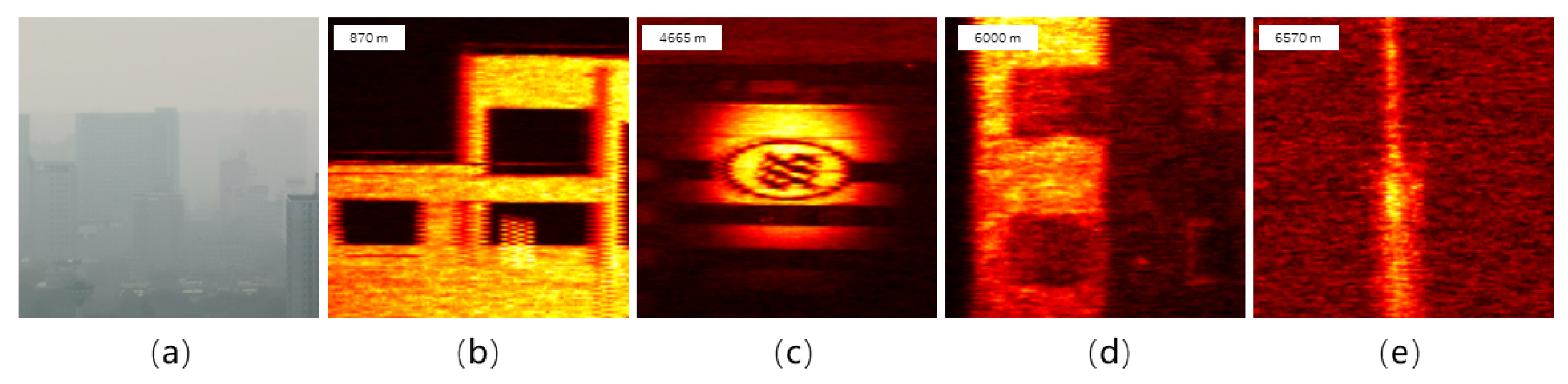
Figure 4.
Imaging in bright daylight. (a) Microwave radar antenna at 150 m. (b) Baluster at 1900 m. (c) House at 2577 m. (d) Tower crane at 4000 m.
Figure 4.
Imaging in bright daylight. (a) Microwave radar antenna at 150 m. (b) Baluster at 1900 m. (c) House at 2577 m. (d) Tower crane at 4000 m.
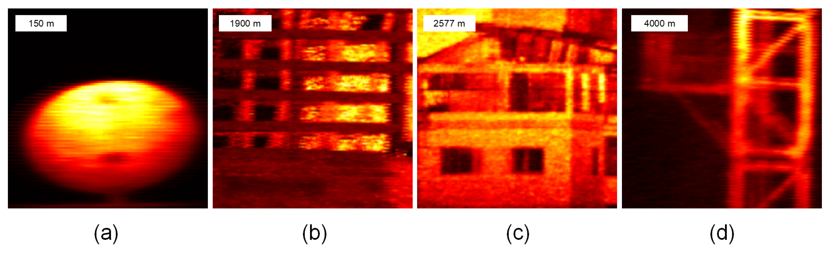
Figure 5.
Imaging at night. (a) Building at 9000 m. (b) TV tower head at 13,000 m. (c) Building at 14,000 m. (d) Building at 192,000 m.
Figure 5.
Imaging at night. (a) Building at 9000 m. (b) TV tower head at 13,000 m. (c) Building at 14,000 m. (d) Building at 192,000 m.
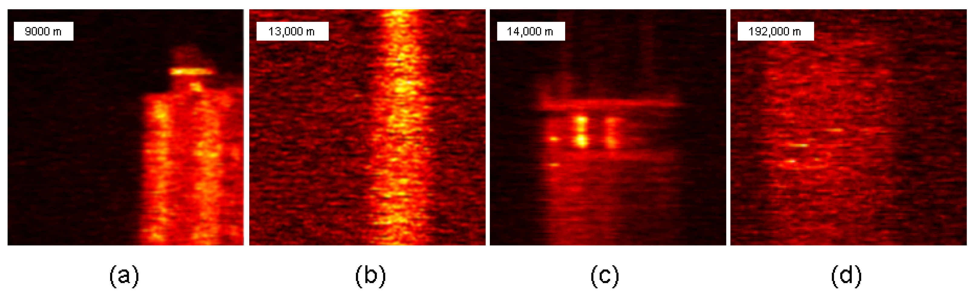
Figure 6.
Imaging on a rainy day. (a) Microwave radar antenna at 150 m. (b) Clock situated atop the building at 250 m. (c) Building under construction located at 1500 m. (d) Attic within the building observed at 2000 m.
Figure 6.
Imaging on a rainy day. (a) Microwave radar antenna at 150 m. (b) Clock situated atop the building at 250 m. (c) Building under construction located at 1500 m. (d) Attic within the building observed at 2000 m.

Figure 7.
Time consumed by imaging reconstruction under different imaging parameters.

Table 1.
A comparison of different camera lenses.
| Aperture/Focal Length | Imaging |
|---|---|
| 105 mm/600 mm |  |
| 200 mm/2000 mm |  |
Table 2.
Capability of the compression-aware algorithm to reconstruct the image as the sampling rate diminishes.
Table 2.
Capability of the compression-aware algorithm to reconstruct the image as the sampling rate diminishes.
| Sampling Rate | 50% | 20% | 10% | 5% |
|---|---|---|---|---|
| Sampling Pattern |  |  |  |  |
| Compressed Sensing |  |  |  |  |
Disclaimer/Publisher’s Note: The statements, opinions and data contained in all publications are solely those of the individual author(s) and contributor(s) and not of MDPI and/or the editor(s). MDPI and/or the editor(s) disclaim responsibility for any injury to people or property resulting from any ideas, methods, instructions or products referred to in the content. |
© 2024 by the authors. Licensee MDPI, Basel, Switzerland. This article is an open access article distributed under the terms and conditions of the Creative Commons Attribution (CC BY) license (https://creativecommons.org/licenses/by/4.0/).
Share and Cite
MDPI and ACS Style
Zheng, H.; Han, Y.; Qiu, L.; Zong, Y.; Li, J.; Zhou, Y.; He, Y.; Liu, J.; Wang, G.; Chen, H.; et al. Long-Range Imaging LiDAR with Multiple Denoising Technologies. Appl. Sci. 2024, 14, 3414. https://doi.org/10.3390/app14083414
AMA Style
Zheng H, Han Y, Qiu L, Zong Y, Li J, Zhou Y, He Y, Liu J, Wang G, Chen H, et al. Long-Range Imaging LiDAR with Multiple Denoising Technologies. Applied Sciences. 2024; 14(8):3414. https://doi.org/10.3390/app14083414
Chicago/Turabian StyleZheng, Huaibin, Yuyuan Han, Long Qiu, Yanfeng Zong, Jingwei Li, Yu Zhou, Yuchen He, Jianbin Liu, Gao Wang, Hui Chen, and et al. 2024. "Long-Range Imaging LiDAR with Multiple Denoising Technologies" Applied Sciences 14, no. 8: 3414. https://doi.org/10.3390/app14083414
Note that from the first issue of 2016, this journal uses article numbers instead of page numbers. See further details here.