
Refinement and Computation Method for Line/Body Topological Relationships
School of Geosciences and Info-Physics, Central South University, Changsha 410083, China
*
Author to whom correspondence should be addressed.
Appl. Sci. 2024, 14(8), 3474; https://doi.org/10.3390/app14083474
Submission received: 12 March 2024
/
Revised: 5 April 2024
/
Accepted: 10 April 2024
/
Published: 20 April 2024
(This article belongs to the Special Issue Recent Advances in Geospatial Big Data Mining)
Abstract
:Three-dimensional topological relationships serve as a theoretical foundation for quality control, update processing, and spatial analysis of three-dimensional spatial data in real-world three-dimensional GIS. The existing 3D topological relationship models are all basic relationship models that cannot distinguish the refined topological relationship between the line and the body with multiple intersections. In this study, we develop a 3D refined topological relationship description framework that draws from the two-dimensional refined topological relationship model, defines the unit intersection between the line and the body based on manifold topology, and proposes a method for describing the unit intersections between the line and the body considering Euler numbers and adjacency types. In total, 23 basic types between the line and the body are deduced. An example is provided to illustrate the distinguished refined topological relationship between the line and the body with multiple intersections. Subsequently, an algorithm for determining the basic type of line/body is developed. Finally, a line/body refined topological relationship computation prototype system is developed using the Nef polyhedron model, C++ language, and an open-source geometric algorithm library, and the effectiveness of our method is verified using actual building and pedestrian data.
1. Introduction
Three-dimensional (3D) geographic information has become important in our everyday life [1]. A three-dimensional realistic geospatial scene is an important new infrastructure in our daily life, and its construction includes the establishment of the ground, underground, indoor, and outdoor geospatial framework of the three-dimensional structure and spatiotemporal relationships, etc. Three-dimensional topological relationships, as the most important and fundamental spatial relationships in a 3D GIS, serve as the theoretical foundation for quality control, updating processing, and spatial analysis of three-dimensional spatial data in realistic 3D construction and 3D GIS [2,3,4,5].
As topological relations are the most important spatial relations [6,7], many researchers have proposed several topological relationship models to distinguish the relations between two-dimensional objects, e.g., the 4-intersection (4I) model [8], 9-intersection (9I) model [9], the region connection calculus (RCC) model [10], the Voronoi-based 9-intersection (V9I) model [11], the Voronoi-based spatial algebraic model [12], and the Euler-number-based whole-object intersection and differences (E-WID) model [13]. Clementini et al. proposed the dimension-extended 9-intersection model (DE+9IM) [14]. Among the above models, 4I and 9I are widely applied in the GIS society, e.g., OGC lists the 9I model as a reference model for 2D topological relationships. Proposed by Egenhofer and Franzosa in 1991, 4I model is based on the point set topology theory [8], which decomposes spatial objects into interiors and boundaries where ∂A, A°, ∂B, and B°,, respectively, represent the boundary and interior of A and the boundary and interior of B. The 4I model uses a 2 × 2 matrix to represent the topological relationships between objects, but its discriminatory ability is limited and, theoretically, capable of distinguishing only 16 types of topological relationships. Clementini et al. further proposed a dimension-extension-based 4I model, which, however, also has limited discriminatory ability [15]. To overcome the limited discriminatory ability of the 4I model, Egenhofer and Herring introduced the exterior of spatial objects into the calculation of topological relationships where A− and B−, respectively, represent the exterior A and B. The 9I model uses a 3 × 3 matrix to represent the topological relationships between objects, theoretically capable of distinguishing 29 = 512 types of topological relationships. However, in practice, it can only distinguish 8 types of region/region, 19 types of line/region, 33 types of line/line, 3 types of point/region, 3 types of point/line, and 2 types of point/point topological relationships.
Due to the widespread influence of the 9I model in two-dimensional space and its relatively simple model structure compared with models created in the same period, it has been extended to three-dimensional space by multiple scholars. This extension has led to the development of methods for describing topological relationships between three-dimensional vector spatial entities, providing initial descriptions of basic topological relationship types between points, lines, regions, and bodies. For example, Zlatanova summarized the topological relationships between three-dimensional spatial entities that can be distinguished using the 9I model [5]. Belussi et al. proposed a 3D vector model consisting of basic vector types, predicates, and operations to implement and test the 9I relationships between three-dimensional vector data [2]. Clementini and Cohn extended RCC*-9 to adopt simplified 3D features and achieved 3D RCC*-9 relations [16]. However, the aforementioned three-dimensional topological relationship models are basic relationship models that can only distinguish a very limited number of basic topological relationship types. They cannot yet distinguish the refinement types of topological relationships between 3D entities that contain multiple intersections.
In the context of the refinement of topological relationships involving multiple intersections, Egenhofer and Franzosa established the BBIS (boundary-boundary intersection set) model to describe refined relationships between regions [17]. Li et al. introduced a hierarchical model for line/line relationships [18]. Deng et al. introduced a multi-level relationship model for region/region relationships based on topological invariants [19]. Chen Jun et al. proposed the topological chain model to describe refined relationships between lines, which they applied in conflict detection for rivers and contour lines [20]. Zhou et al. developed the WWIS (whole-whole intersection set) model based on the intersection set operation results of spatial objects as a whole. They provided a comprehensive and distinct description of refined relationships between regions, lines, and lines/regions by using node degrees and Euler numbers [13,21].
In addition to the refined relationships mentioned above, Egenhofer et al. developed a model of conceptual neighborhoods’ topological line–region relationships [6]. Kurata et al. proposed the 9+-intersection model for directed line segments and regions [22]. Tang et al. distinguished 152 kinds of topological relationships for simple fuzzy regions [23]. Wu et al. proposed a model and computational method for describing relationships between lines and regions [24]. Formica et al. proposed the directed polyline–polygon model [25]. Zhou et al. proposed the 25I model by decomposing spatial objects into vertex, edge, face, interior, and exterior [26]. Shen et al. introduced a topological relationship model that distinguishes between directed lines and directed regions [27] and the 27-intersection model in two-dimensional space [28]. Based on the 9I model, Leng et al. proposed the generalized 9-intersection model for regions with multiple holes [29]. Zhang et al. proposed a three-dimensional electronic navigation charts (3D ENC) feature spatial relation model (3DSRM) based on point-set topology theory, which combines 3D topological relations, distance relations, and directional relations [30].
In summary, the refined topological relationships between lines and bodies are still an open issue to date. Therefore, we propose a model to represent the refined topological relationships between lines and bodies using dimension information, Euler numbers, the number of intersections between the line and the body’s boundary, predicates, and topological sequences in this study. As Zhou et al.’s WWIS + BBIS refined models, based on the intersection components of the spatial objects as a whole, along with their E-WID coarse model, have formed a complete framework for describing and computing two-dimensional topological relationships using manifold without theoretical deficiency, this framework has the potential to be extended to the 3D space. This study adopts the intersection component concept of this framework and, by defining the 3D line/body intersection component (unit intersection), develops a method to describe 3D line/body unit intersections and derive their types. It establishes an expression model for the refined relationships of 3D lines/bodies. Furthermore, it proposes a calculation algorithm for line/body topological relationships and implements the automatic calculation of line/body refined topological relationships by using an open-source geometric algorithm library.
2. Method for Refinement of Topological Relationships between Line and Body
As mentioned above, the existing 3D topological relationship model cannot distinguish the refinement relations between 3D objects with multiple intersections. However, in real application scenarios, there are many cases with multiple intersections, and different types of intersections often require different processing methods. In this section, we provide an application scenario first and then define the 3D object using the manifold and model the framework for refinement of topological relationships between the line and the body.
2.1. Application Scenario for Topological Relationships between the Line and the Body with Multiple Intersections
In the 3D real world, there are many real scenes where a line and a body have multiple intersections, e.g., an electric-power line, a water pipeline, a gas pipeline and a building. Furthermore, with the rapid development of indoor positioning technologies today, integrated indoor–outdoor navigation services have become a hot research topic in the GIS field. Constructing high-quality integrated indoor–outdoor pedestrian networks is a primary task for integrated indoor–outdoor navigation [31]. While in the indoor–outdoor navigation system, there may be several intersections between a pedestrian pathway and a building (Figure 1).
Figure 1 illustrates the integrations between indoor and outdoor pedestrian pathways and buildings. Currently, people generally utilize multi-source (including crowdsourced) data to generate integrated indoor–outdoor pedestrian pathways. However, due to the influence of data quality from multiple sources and indoor positioning accuracy, the generated integrated indoor–outdoor pedestrian pathway data often suffer from various quality issues. Figure 1 presents an example from the open-source dataset depicting the relationship between integrated indoor–outdoor pedestrian pathways and buildings in Hong Kong. In this dataset, buildings are represented as three-dimensional bodies while pedestrian pathways are abstracted as 3D lines. The core attributes of pedestrian pathways include features such as “Indoor” and “Outdoor”. Figure 1a illustrates a two-dimensional projection of a building and a pedestrian pathway dataset. In this projection, p1 to p5 represent five nodes of the pedestrian pathway, while e1 to e4 represent the four segments formed by these five nodes. It is evident from Figure 1a that p1 and p5 are located outside the building, while p2, p3, and p4 are situated on the surface of the building. Additionally, e1 and e4 are positioned outside the building, while e2 and e3 are within. However, the attribute of this pedestrian pathway is labeled as “Indoor”. Clearly, there are multiple intersections between the 3D building and the pedestrian pathway, with some of these intersections involving conflicts between topological and semantic attributes. During data quality inspection and processing, it is necessary to address each intersection separately based on its specific characteristics. For example, if p1 and p2 belong to the same point within the tolerance range, e1 can be deleted; otherwise, the attributes of e1 will be changed to “Outdoor”. Similarly, if p4 and p5 are within the same point tolerance range, e4 can be removed; otherwise, its attribute should be changed to “Outdoor”. Existing 3D basic topological relationship models for lines/bodies have not yet expressed the refinement of each intersection, making it challenging to support applications such as 3D conflict detection and processing involving multiple intersections.
According to the 2D WWIS refined topological relationship model proposed by Zhou et al., the detailed topological relationships between 3D entities with multiple intersections can be described by Equation (1):
where m represents the number of unit intersections resulting from the whole-whole intersection set operation between spatial entities A and B. Ni, di, and ti (1 ≤ i ≤ m) denote the topological sequence number, dimension, and topological type of each unit intersection, respectively. This framework is applied in this study to differentiate the refined topological relationships between 3D lines and bodies. From Equation (1), it can be observed that the core issue in refined topological relationships between lines and bodies lies in defining and distinguishing the unit intersections of lines and bodies. Therefore, we first define the 3D body and line continuing to use manifold topology theory and then define unit intersections on this basis.
2.2. Definition of 3D Objects and Line/Body Unit Intersections with Manifold Topology
Given that manifold topology better aligns with the cognitive habits of individuals in the GIS field regarding spatial objects, Zhou et al. have adopted it to define two-dimensional objects and differentiate two-dimensional topological relationships. Due to the complexity of the geometric shapes and topological properties of three-dimensional spatial objects, the following sections initially utilize manifold topology to define 3D simple points, lines, bodies, and their interiors and boundaries [32,33] (see Figure 2).
Definition 1:
A simple point is a zero-dimensional manifold with only an interior and no boundary (Figure 2a).
Definition 2:
A simple body is a three-dimensional manifold with a connected interior and a connected boundary, and is homeomorphic to a solid cube (Figure 2b).
Definition 3:
A simple line is a one-dimensional manifold with a connected interior and two distinct boundary points (Figure 2c).
It should be noted that three-dimensional manifolds (bodies) can have tunnels or voids. Such three-dimensional manifolds with voids or tunnels are referred to as complex manifolds. For simplicity, we do not discuss complex manifolds in this article. Therefore, the lines and bodies studied here are topologically equivalent to connected, orientable, compact one-dimensional and three-dimensional manifolds. Thus, the unit intersections of lines/bodies can be defined as follows:
Definition 4:
Let A and B be the 3D body and line objects, respectively, and I be the largest connected subset of A∩B. Let P = {P1, P2, …, Pm} be a subset of I where P ∈ I. If Pj (0 ≤ j ≤ m) is a zero-dimensional manifold (point), then Pj is a unit intersection (point) of A∩B. Let L = {l1, l2, …, ln} where L ∈ I. If li (0 ≤ i ≤ n) is a one-dimensional manifold (line) and the interior of li equals the largest connected subset of ∂A∩li or A°∩li, then li is a unit intersection (line) of A∩B. Moreover, I = (i ≥ 0) ∪ (j ≥ 0)
As shown in Figure 3, the intersection of body A and line B has four connected subsets, namely, the polyline (ab) (cdefg) and isolated points h and i. Among them, h and i are isolated points, and two unit intersections (points) of A∩B are marked as 6 and 7. According to the definition of unit intersections, the polyline (cdefg) needs to be subdivided into four unit intersections: cd, de, ef, and fg. Therefore, the four connected subsets of the intersection between body A and line B include seven unit intersections, namely, intersection lines ab, cd, de, ef, and fg, and intersection points h and i. The intersection lines can be preliminarily classified into three types: ① the interior of ab and endpoint a are inside body A, while endpoint b is on the boundary of A; ② the endpoints and interior of cd and ef are all on the boundary of A; ③ the interior of de and fg is inside body A, and both endpoints are on the boundary of A. The connectivity of intersection points i and h is also different.
The situation of line/body intersection points is relatively simple, as they can only intersect on the surface of the body, as shown in the two cases in Figure 3. However, the situation of line/body intersection lines can be much more complex. Obviously, in natural language, people often communicate whether the line and its endpoints are on the boundary of the body. It is relatively easy to identify whether the endpoint is on the boundary, but whether the line as a whole is on the boundary or inside the body cannot be determined solely by the endpoints. For example, the two endpoints of the intersecting lines cd, de, ef, and fg are all on the boundary of body A, but the intersecting lines ef and cd are on the boundary of body A, while de and fg are inside body A. It is noted that fE(A/ef) = 1, fE(A/cd) = 1, fE(A/de) = 0, and fE(A/fg) = 0. Therefore, the Euler number can better distinguish these two cases.
Upon closer analysis of ed, fg, ef, and cd, it is evident that their connectivity status still differs, and this difference remains important in three-dimensional data conflict detection and processing. For instance, assuming line B represents a pedestrian walkway and A represents a building structure, although ef and cd are both on the boundary of A, the two segments of the pedestrian walkway connected by ef, namely, ed and fg, are both inside A, suggesting that ef is likely an indoor pedestrian walkway (such as an elevator or staircase) within the building. On the other hand, one end of the pedestrian walkway connected by cd is inside A, while the other end is outside A, indicating that cd is likely an outdoor pedestrian walkway. From Figure 3, it can be observed that each intersection line consists of two endpoints, and each endpoint may have different connectivity states. There may be no connecting line segment at the endpoint (denoted as null), as seen in endpoint a of intersection line 1 in Figure 3. The connecting line segment may be outside the body an object (denoted as out), as seen in endpoint b of intersection line 1 and endpoint c of intersection line 2 in Figure 3. The connecting line segment may lie on the boundary of the body object (denoted as on), as seen in both endpoints, e and d, of intersection line 3 in Figure 3. The connecting line segment may be inside the body object (denoted as in), as seen in both endpoints, e and f, of intersection line 4 in Figure 3. Therefore, this study distinguishes the types of line/body unit intersections based on the dimension of the unit intersection (fD), the number of intersections between the endpoints of the intersection line and the body surface (fS), the Euler number of the difference of the body with the unit intersection (fE), and the connectivity state predicate of the endpoints of the unit intersection (fR) (Equation (2)).
According to Equation (2), the basic types of line/body unit intersections can be derived based on the values of fD, fS, fE, fR.
3. Derivation and Computation of Basic Intersection Types
3.1. Derivation of Basic Intersection Types
Clearly, in Equation (2), the values of the dimension of line/body intersection fD include only two cases: {0, 1}. The cases where the endpoints of the intersecting lines are on the surface of the body, denoted by fS, encompass three possible values: 0 indicates that neither of the endpoints of the intersecting line lies on the boundary of the body; 1 indicates that one endpoint of the intersecting line lies on the boundary of the body; and 2 indicates that both endpoints of the intersecting line lie on the boundary of the body. Assuming that the body is A and the intersection line is li, the values of fE(A/li) include three cases: {0, 1, 2}; the predicate fR represents the connection types of the two endpoints of unit intersection, each containing four cases, {null, out, on, in}, totaling 16 cases. Therefore, there is a total of 2 × 3 × 3 × 16 = 288 possible types of line/body basic intersections. Below, the method of exclusion is used to eliminate meaningless cases.
- (1)
- fD = 0, indicating that the line/body intersection occurs at a point, which includes only the two cases shown in Figure 4a,b.
- (2)
- fD = 1, fS = 0, meaning both endpoints of the intersection line are inside the body. In this case, fE = 2, and it only includes the situation depicted in Figure 4c.
- (3)
- fD = 1, fS = 1, indicating that one endpoint of the intersection line is inside the body, while the other is on the body’s boundary. Therefore, fE = 1. According to the definition of the unit intersection, the endpoint inside the body is an endpoint of the line object without subsequent connecting line segments, resulting in a fR value of “null”. Hence, it includes only the four cases shown in Figure 4d–g.
When fD = 1 and fS = 2, fE can take two values: {0, 1}.
- (4)
- When fD = 1, fS = 2, and fE = 1, it means that the intersection line (including its interior and both endpoints) lies entirely on the surface of the body. According to the definition of the unit intersection, it is not possible for fR to be “on”. Excluding symmetrical cases, only the six cases shown in Figure 4h–m are included.
When fD = 1, fS = 2, and fE = 0, it means that the intersection line, except for its two endpoints, lies entirely inside the body. Each of the two endpoints can take one of four possible values: {null, out, on, in}. This results in a total of 16 meaningful combinations. There are 10 cases, excluding symmetric cases, as shown in Figure 4n–w.
Figure 4.
Three-dimensional line/body basic types and their formal representation.

Therefore, there are a total of 2 intersection points and 21 intersection lines, resulting in 23 basic types between the line and the body (as illustrated in Figure 4).
After defining all the basic types, the representation of the line/body relationships in Figure 3 according to Equation (1) is as follows:
R(A, B) = <1 (1, 1, 1, null, out), 2 (1, 2, 1, out, in), 3 (1, 2, 0, on, on), 4 (1, 2, 1, in, in), 5 (1, 2, 0, on, out), 6 (0, out, out), 7 (0, out, null)>.
The following section discusses the method for calculating the refined topological relationships between the line and body.
3.2. Refinement Relationship Computation
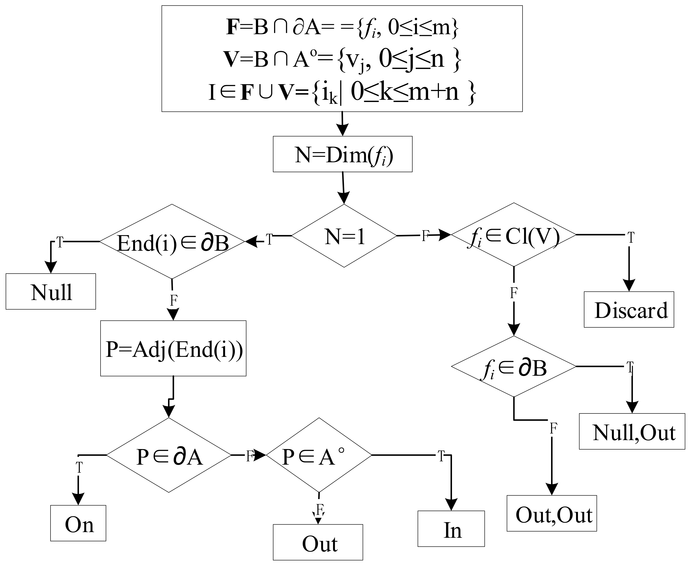
From Figure 4, it can be observed that among the 2 intersection points and 21 intersection lines between lines and bodies, the types of intersection points are entirely determined by the adjacency conditions “null, out” and “out, out”. Among the 21 intersection lines, the adjacency conditions of their endpoints are expressed by “null, out, on, in”, which play a crucial role in determining the basic types of intersection lines. Therefore, the following discussion focuses on the method of determining the adjacency relationships of intersection line endpoints. First, it is necessary to define the symbols and functions used in the computation of refinement relationships.
The participating body object is denoted as A, and the line object is denoted as B. The boundary of A is represented as ∂A, the interior of A is represented as Ao, ∂B represents the boundary of B, and Bo represents the interior of B.
Let F = ∂A∩B = {fi, 0 ≤ i ≤ m} where F represents the set of intersections between the boundary of A and B. Each fi includes two main categories: intersection points and intersection lines.
Let V = A°∩B = {vj| 0 ≤ j ≤ n} where V represents the set of intersections between the interior of A and B. Each vj only includes intersection lines.
I = F∪V= {ik|0 ≤ k ≤ m + n} where I represents the union of F and V, containing all subsets of F and V.
Let Dim(i) denote the dimension of i, with possible values of 0 and 1: End(i) represents taking one endpoint of i; Cl(i) represents taking the closure of i; Adj(End(i)) denotes taking a point on the next line segment of B connected to the endpoint of i, specifically taking a point on the intersection of the surface of a small ball with radius ε centered at the endpoint of i and the next line segment of B. The method for determining the adjacency relationship of basic intersections is illustrated in Figure 5.
As shown in Figure 5, the process for determining adjacency conditions in line/body refinement relationships is as follows:
- (1)
- Intersect the line object B with the boundary and interior of the body object A separately to obtain F and V and let I = F∪V.
- (2)
- Since, mathematically, the interior intersections in V of the line/body do not include points on the boundary of the body object A, some isolated points in the line/body boundary intersections F are not unit intersections of the line/body but rather boundary points at the closure of some intersection lines vi inside the line/body (i.e., endpoints of intersection lines that traverse the boundary of the body object in GIS). Therefore, we first need to extract these points from F, determining whether the closure of the elements vi in V intersects with these isolated points in F. If there is no intersection, the point is a unit intersection; otherwise, the point, along with its adjacent intersection line vi in the interior of the line/body, forms an intersection line of the line/body (with the point being an endpoint of the intersection line). Since this part constitutes derived points and is not a unit intersection of the line/body, it is marked for “discard” processing.
- (3)
- For the intersection points in F, their adjacency conditions still need to be determined. The method is as follows: if the unit intersection point is on the boundary (endpoint) of the line object, then its adjacency predicate is “null, out” (as shown in Figure 4a); otherwise, its adjacency type is “out, out” (as shown in Figure 4b).
- (4)
- For the unit intersection of lines, first extract the endpoints (End(i)). If this point is also a boundary point of the line object, then its adjacency predicate is “null” (as shown in Figure 4c–j,n–q); otherwise, take its adjacent point near this intersection endpoint by a distance ε (slightly larger than the tolerance) (Adj(End(i))) and determine the relationship between this adjacent point and the body object. If this adjacent point is outside the body object, then the adjacency predicate is “out” (as shown in Figure 4g,k, etc.). If this adjacent point is inside the body object, then the adjacency predicate is “in” (as shown in Figure 4m,u, etc.); otherwise, the adjacency predicate is “on” (as shown in Figure 4q,t,w, etc.). This process allows us to determine the adjacency type of all endpoints of the intersection lines one by one.
To determine the basic type of each intersection, we also need to determine the values of fE and fS in Equation (2). fS represents the number of intersections between the endpoints of the intersection lines and the surface of the body. In the method for determining the unit intersection adjacency relationship in Figure 5, we have already determined the relationship between each intersection endpoint and the boundary of the body object A, indirectly determining the value of fS. Next, we focus on discussing the method for determining fE. In theory, the Euler number of a three-dimensional manifold with a boundary can be calculated according to Equation (3):
where b0 can represent the number of connected components of the body object, b1 represents the number of channels in the body object, and b2 represents the number of voids in the body object [34]. The value of the Euler number fE in this study can be simplified based on the positions of the two endpoints of the intersection lines—for example, for intersection lines in F where b0 = 1, b1 = 0, and b2 = 0, fE = b0 − b1 + b2 = 1. For unit intersections in V, if both endpoints are on the surface of the body (as in Figure 4n–q, etc.), b0 = 1, b1 = 1, b2 = 0, then fE = b0 − b1 + b2 = 0. If both endpoints are inside the body (as in Figure 4c), b0 = 1, b1 = 0, b2 = 1, then fE = b0 − b1 + b2 = 2; otherwise, if one endpoint is inside the body and the other is on the surface of the body (as shown in Figure 4f,g, etc.), b0 = 1, b1 = 0, b2 = 0, then fE = b0 − b1 + b2 = 1.
Thus, we can determine the basic type of each intersection line between the line and the body. Then, by sorting the unit intersections in the order from the starting point to the endpoint of the line object, we can obtain the expression of the refinement relationship between the involved line and the body.
4. Experimental Validation
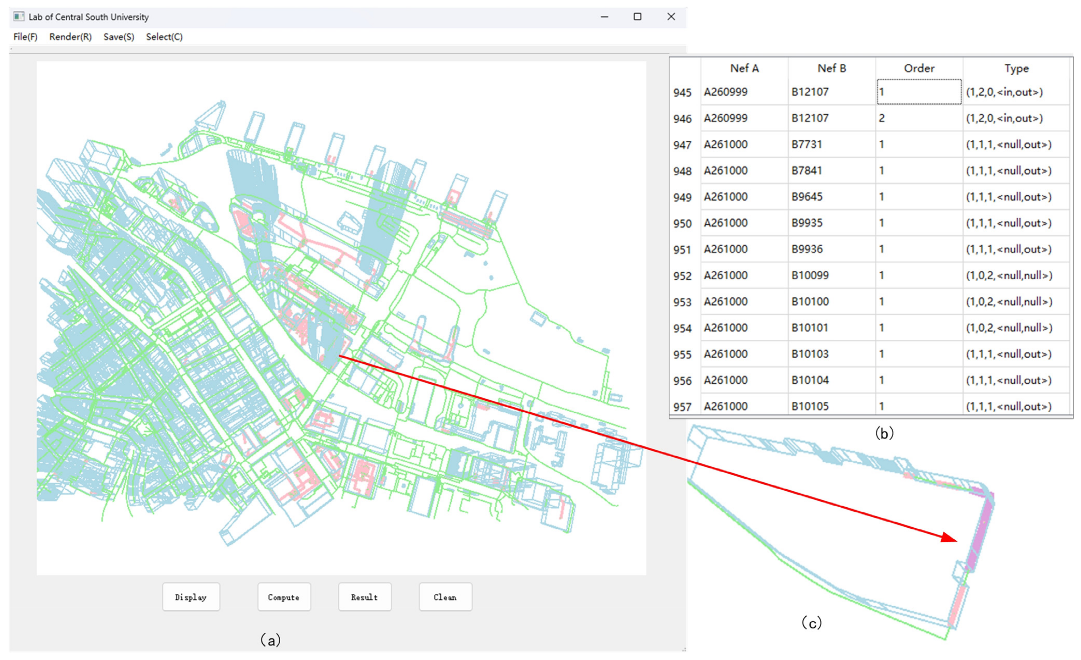
To validate the effectiveness of the proposed model and algorithm in this study, we developed a prototype system for computing the refined topological relationships between simple lines and bodies by using the Nef polyhedron model [35,36,37], C++ language, QT framework, and the Computational Geometry Algorithms Library (CGAL). We conducted experiments by using real pedestrian walkway lines (including “Indoor” and “Outdoor” attributes) and building body data from Hong Kong for validation [38], which include 925 building bodies and 4409 pedestrian walkway lines (see Figure 6). For body data, open data include the three-dimensional coordinates of the building’s base, the height of the building, and various attribute data such as the type of building, name, construction date, and area. For line data, the most important attribute information includes the three-dimensional coordinates and position (“Indoor” or “Outdoor”) of the line data. This also encompasses attributes such as name and length.
The computation results are depicted in Figure 6, where blue represents buildings, green represents pedestrian pathways, pink denotes unit intersections, and purple indicates selected unit intersections. In Figure 6b, the column labeled “NefA” represents the involved buildings, “NefB” represents the pedestrian lines, “Order” indicates the sequence of basic intersections, and “Type” denotes the value of basic intersection types shown in Figure 4. For example, rows number “945” and “946” have the same NefA (A260999) and NefB (B12107), but different order “1” and “2”, which indicates that there are two intersections between A260999 and B12107, and the type of value “1, 2, 0, in, out” corresponds to Figure 4s (same as “1, 2, 0, out, in”). In total, there are 1519 unit intersections between pedestrian pathways and buildings, encompassing 20 types. After calculation, there are 227 lines that have 1 of the 23 basic types, but the attribute is labeled as “outdoor”, which means that the topological relationship type of these 227 lines of data conflicts with the attribute data. Detailed information is provided in Table 1.
5. Conclusions and Discussion
The existing 3D topological relationship models are all basic relationship models that cannot distinguish the refined topological relationship between the line and the body with multiple intersections. Building upon the WWIS 2D topological refinement model, we have developed a 3D refinement of the topology description model for lines and bodies. This model defines the concept of line/body unit intersections and proposes a method for distinguishing between them based on dimension, Euler numbers, and predicates for connecting intersection endpoints. On this basis, we have derived 2 types of intersection points and 21 types of intersection lines between lines and bodies, illustrating the description method for the refinement of topology relationships involving multiple intersections. Furthermore, we have developed algorithms for determining the types of adjacency endpoints for intersection points and intersection lines, as well as for calculating the Euler numbers and the number of intersection points between endpoints of intersection lines and the surface of bodies. In summary, the main contributions of this paper are listed as follows:
- (1)
- Based on manifold topology theory, a 3D line and body are defined, followed by the definition of unit intersections between the line and the body.
- (2)
- Based on the unit intersections, basic intersection types between the line and the body are deduced and distinguished using the dimensions of unit intersections, Euler numbers, the number of intersections between unit intersections and body boundaries, and predicates. Finally, 23 basic types of line/body are distinguished, and through these 23 basic types and the topological sequence of basic types, all refinement relations are represented.
- (3)
- This paper describes the computation method of basic types and validates the effectiveness of the model using real three-dimensional data.
Finally, we have implemented the computation of 3D line/body refined topological relationships using the Nef polyhedron model for representation, C++ programming language, and CGAL open-source library. We have validated the effectiveness of our approach and demonstrated its feasibility for applications such as conflict detection between building structures and pedestrian pathways using real-world building and pedestrian pathway data from Hong Kong.
Since this paper only focuses on the refinement of topological relationships between simple lines and bodies, the body objects cannot have channels or voids. Future research will focus on other spatial entities, such as the refinement of topological relationships between lines/regions, regions/bodies, and bodies/bodies, as well as the refinement of relationships between complex spatial entities. In addition, the application of research outcomes in practical production is closely associated with specific application scenarios. Given the potential variation in conflict detection rules across different application scenarios, devising corresponding conflict detection rules based on the specific application will also be the focus of our future work.
Author Contributions
Conceptualization, X.Z., X.W. and D.H.; methodology, X.W., X.Z. and D.H.; validation, X.W.; writing—original draft preparation, X.W. and X.Z.; validation and formal analysis, Q.K. and N.A.; funding acquisition, X.Z. All authors have read and agreed to the published version of the manuscript.
Funding
This research was funded by the National Natural Science Foundation of China, Grant Number 41971360, and the National Key Research and Development Program of China, Grant Number 2022YFB390420501.
Institutional Review Board Statement
Not applicable.
Informed Consent Statement
Not applicable.
Data Availability Statement
The original contributions presented in the study are included in the article, further inquiries can be directed to the corresponding author.
Acknowledgments
The authors would also like to thank the anonymous reviewers for their comments on how to improve this article.
Conflicts of Interest
The authors declare no conflicts of interest.
References
- Arroyo Ohori, K. azul: A fast and efficient 3D city model viewer for macOS. Trans. GIS 2020, 24, 1165–1184. [Google Scholar] [CrossRef]
- Belussi, A.; Migliorini, S.; Negri, M.; Pelagatti, G. A template-based approach for the specification of 3D topological constraints. GeoInformatica 2020, 24, 683–712. [Google Scholar] [CrossRef]
- Li, L.; Luo, F.; Zhu, H.; Ying, S.; Zhao, Z. A two-level topological model for 3D features in CityGML. Comput. Environ. Urban Syst. 2016, 59, 11–24. [Google Scholar] [CrossRef]
- Salleh, S.; Ujang, U.; Azri, S. 3D topological support in spatial databases: An overview. ISPRS Arch. 2021, 46, 473–478. [Google Scholar] [CrossRef]
- Zlatanova, S. Topological Relationships and Their Use. In Encyclopedia of GIS; Springer: Berlin/Heidelberg, Germany, 2016; pp. 1–21. [Google Scholar]
- Egenhofer, M.J.; Mark, D.M. Modelling conceptual neighbourhoods of topological line-region relations. Int. J. Geogr. Inf. Sci. 1995, 9, 555–565. [Google Scholar] [CrossRef]
- Laurini, R.; Thompson, D. Fundamentals of Spatial Information Systems; Academic Press: Cambridge, MA, USA, 1992; Volume 37. [Google Scholar]
- Egenhofer, M.J.; Franzosa, R.D. Point-set topological spatial relations. Int. J. Geogr. Inf. Sci. 1991, 5, 161–174. [Google Scholar] [CrossRef]
- Egenhofer, M.J.; Herring, J. Categorizing binary topological relations between regions, lines, and points in geographic databases. Stat. Inf. Forum 1990, 9, 76. [Google Scholar]
- Randell, D.A.; Cui, Z.; Cohn, A.G. A spatial logic based on regions and connection. KR 1992, 92, 165–176. [Google Scholar]
- Chen, J.; Li, C.; Li, Z.; Gold, C. A Voronoi-based 9-intersection model for spatial relations. Int. J. Geogr. Inf. Sci. 2001, 15, 201–220. [Google Scholar] [CrossRef]
- Li, Z.; Zhao, R.; Chen, J. A Voronoi-based spatial algebra for spatial relations. Prog. Nat. Sci. 2002, 12, 528–536. [Google Scholar]
- Zhou, X.-G.; Chen, J.; Zhan, F.B.; Li, Z.; Madden, M.; Zhao, R.-L.; Liu, W.-Z. A Euler number-based topological computation model for land parcel database updating. Int. J. Geogr. Inf. Sci. 2013, 27, 1983–2005. [Google Scholar] [CrossRef]
- Clementini, E.; Di Felice, P. A comparison of methods for representing topological relationships. Inf. Sci. Appl. 1995, 3, 149–178. [Google Scholar] [CrossRef]
- Clementini, E.; Di Felice, P.; Van Oosterom, P. A small set of formal topological relationships suitable for end-user interaction. In Proceedings of the International Symposium on Spatial Databases, Singapore, 23–25 June 1993; pp. 277–295. [Google Scholar]
- Clementini, E.; Cohn, A.G. Extension of RCC*-9 to Complex and Three-Dimensional Features and Its Reasoning System. ISPRS Int. J. Geo-Inf. 2024, 13, 25. [Google Scholar] [CrossRef]
- Egenhofer, M.J.; Franzosa, R.D. On the equivalence of topological relations. Int. J. Geogr. Inf. Sci. 1995, 9, 133–152. [Google Scholar] [CrossRef]
- Li, Z.; Deng, M. A hierarchical approach to the line-line topological relations. In Proceedings of the Progress in Spatial Data Handling: 12th International Symposium on Spatial Data Handling, Vienna, Austria, 12–14 July 2006; pp. 365–382. [Google Scholar]
- Deng, M.; Cheng, T.; Chen, X.; Li, Z. Multi-level topological relations between spatial regions based upon topological invariants. GeoInformatica 2007, 11, 239–267. [Google Scholar] [CrossRef]
- Chen, J.; Liu, W.; Li, Z.; Zhao, R.; Cheng, T. Detection of spatial conflicts between rivers and contours in digital map updating. Int. J. Geogr. Inf. Sci. 2007, 21, 1093–1114. [Google Scholar] [CrossRef]
- Zhou, X.; He, H.; Hou, D.; Li, R.; Zheng, H. A refined lines/regions and lines/lines topological relations model based on whole-whole objects intersection components. ISPRS Int. J. Geo-Inf. 2021, 10, 15. [Google Scholar] [CrossRef]
- Kurata, Y.; Egenhofer, M.J. The 9+-Intersection for Topological Relations between a Directed Line Segment and a Region. BMI 2007, 76, 62–76. [Google Scholar]
- Tang, X.; Kainz, W.; Wang, H. Topological relations between fuzzy regions in a fuzzy topological space. Int. J. Appl. Earth Obs. Geoinf. 2010, 12, S151–S165. [Google Scholar] [CrossRef]
- Wu, C. Detailed model of topological and metric relationships between a line and region. Arabian J. Geosci. 2019, 12, 130. [Google Scholar] [CrossRef]
- Formica, A.; Mazzei, M.; Pourabbas, E.; Rafanelli, M. Enriching the semantics of the directed polyline–polygon topological relationships: The DLP-intersection matrix. J. Geogr. Syst. 2017, 19, 175–196. [Google Scholar] [CrossRef]
- Zhou, M.; Guan, Q. A 25-intersection model for representing topological relations between simple spatial objects in 3-D space. ISPRS Int. J. Geo-Inf. 2019, 8, 182. [Google Scholar] [CrossRef]
- Shen, J.; Huang, Y.; Chen, M. Topological relations between a directed line and a directed region. Trans. GIS 2020, 24, 526–548. [Google Scholar] [CrossRef]
- Shen, J.; Zhou, T.; Chen, M. A 27-intersection model for representing detailed topological relations between spatial objects in two-dimensional space. ISPRS Int. J. Geo-Inf. 2017, 6, 37. [Google Scholar] [CrossRef]
- Leng, L.; Wang, F.; Wang, M.; Yang, G.; Niu, X.; Zhang, X. A Generalized 9-Intersection Model for Topological Relations between Regions with Holes. ISPRS Int. J. Geo-Inf. 2022, 11, 218. [Google Scholar] [CrossRef]
- Zhang, Y.; Zhang, A.; Gao, M.; Liang, Y. A Spatial Relation Model of Three-Dimensional Electronic Navigation Charts Based on Point-Set Topology Theory. ISPRS Int. J. Geo-Inf. 2023, 12, 259. [Google Scholar] [CrossRef]
- Zhou, B.; Zheng, T.; Huang, J.; Zhang, Y.; Tu, W.; Li, Q.; Deng, M. A pedestrian network construction system based on crowdsourced walking trajectories. IEEE Internet Things J. 2020, 8, 7203–7213. [Google Scholar] [CrossRef]
- Lee, J. Introduction to Topological Manifolds; Springer Science & Business Media: Berlin/Heidelberg, Germany, 2010; Volume 202. [Google Scholar]
- Tu, L.W. Manifolds. In An Introduction to Manifolds; Springer: Berlin/Heidelberg, Germany, 2011; pp. 47–83. [Google Scholar]
- Lee, C.-N.; Poston, T.; Rosenfeld, A. Holes and genus of 2D and 3D digital images. CVGIP Graph. Models Image Process. 1993, 55, 20–47. [Google Scholar] [CrossRef]
- Bieri, H. Nef Polyhedra: A Brief Introduction; Springer: Berlin/Heidelberg, Germany, 1995. [Google Scholar]
- Dobrindt, K.; Mehlhorn, K.; Yvinec, M. A complete and efficient algorithm for the intersection of a general and a convex polyhedron. In Proceedings of the Algorithms and Data Structures: Third Workshop, WADS’93, Montréal, QC, Canada, 11–13 August 1993; pp. 314–324. [Google Scholar]
- Hachenberger, P.; Kettner, L.; Mehlhorn, K. Boolean operations on 3D selective Nef complexes: Data structure, algorithms, optimized implementation and experiments. Comput. Geom. Theory Appl. 2007, 38, 64–99. [Google Scholar] [CrossRef]
- Kong, G.o.H. Common Spatial Data Infrastructure Portal. Available online: https://portal.csdi.gov.hk/csdi-webpage/ (accessed on 22 September 2023).
Figure 1.
Example of multiple intersections between a 3D building and pedestrian pathway: (a) example of multiple intersections between the line and the body (2D); (b) example of multiple intersections between the line and the body (3D).
Figure 1.
Example of multiple intersections between a 3D building and pedestrian pathway: (a) example of multiple intersections between the line and the body (2D); (b) example of multiple intersections between the line and the body (3D).

Figure 2.
Diagram of the interior and boundary of n (0 ≤ n ≤ 3)-dimensional manifolds, with the yellow portions representing their neighborhood: (a) neighborhood of point interior and point boundary; (b) neighborhood of body boundary and body interior; (c) neighborhood of line boundary and line interior.

Figure 3.
Example of multiple unit intersections.

Figure 5.
Process and approach for determining basic types of adjacency relationships.

Figure 6.
Three-dimensional representation of the experimental area, with blue representing bodies, green representing lines and pink representing unit intersections: (a) experimental data; (b) experimental results; (c) zoomed-in view of the region illustrated in Figure 1.
Figure 6.
Three-dimensional representation of the experimental area, with blue representing bodies, green representing lines and pink representing unit intersections: (a) experimental data; (b) experimental results; (c) zoomed-in view of the region illustrated in Figure 1.


Table 1.
Types and quantities of unit intersections.
| C | Type | No. | C | Type | No. |
|---|---|---|---|---|---|
| (a) | (0, <out, null>) | 7 | (b) | (0, <out, out>) | 1 |
| (c) | (1, 0, 2, <null, null>) | 1115 | (d) | (1, 1, 1, <null, on>) | 4 |
| (e) | (1, 1, 1, <null, in>) | 5 | (f) | (1, 1, 1, <null, null>) | 5 |
| (g) | (1, 1, 1, <null, out>) | 342 | (h) | (1, 2, 1, <null, null>) | 1 |
| (i) | (1, 2, 1, <null, out>) | 1 | (j) | (1, 2, 1, <null, in>) | 4 |
| (k) | (1, 2, 1, <out, out>) | 3 | (l) | (1, 2, 1, <out, in>) | 1 |
| (m) | (1, 2, 1, <in, in>) | 1 | (n) | (1, 2, 0, <null, null>) | 1 |
| (o) | (1, 2, 0, <null, out>) | 2 | (r) | (1, 2, 0, <out, out>) | 21 |
| (s) | (1, 2, 0, <out, in>) | 2 | (u) | (1, 2, 0, <in, in>) | 1 |
| (v) | (1, 2, 0, <on, in>) | 1 | (w) | (1, 2, 0, <on, on>) | 1 |
Disclaimer/Publisher’s Note: The statements, opinions and data contained in all publications are solely those of the individual author(s) and contributor(s) and not of MDPI and/or the editor(s). MDPI and/or the editor(s) disclaim responsibility for any injury to people or property resulting from any ideas, methods, instructions or products referred to in the content. |
© 2024 by the authors. Licensee MDPI, Basel, Switzerland. This article is an open access article distributed under the terms and conditions of the Creative Commons Attribution (CC BY) license (https://creativecommons.org/licenses/by/4.0/).
Share and Cite
MDPI and ACS Style
Zhou, X.; Wang, X.; Hou, D.; Kang, Q.; Ali, N. Refinement and Computation Method for Line/Body Topological Relationships. Appl. Sci. 2024, 14, 3474. https://doi.org/10.3390/app14083474
AMA Style
Zhou X, Wang X, Hou D, Kang Q, Ali N. Refinement and Computation Method for Line/Body Topological Relationships. Applied Sciences. 2024; 14(8):3474. https://doi.org/10.3390/app14083474
Chicago/Turabian StyleZhou, Xiaoguang, Xiaohan Wang, Dongyang Hou, Qiankun Kang, and Nawaz Ali. 2024. "Refinement and Computation Method for Line/Body Topological Relationships" Applied Sciences 14, no. 8: 3474. https://doi.org/10.3390/app14083474
Note that from the first issue of 2016, this journal uses article numbers instead of page numbers. See further details here.