Figure 1.
View of a virtual model of CPM rehabilitation device: (1) CPM unit; (2) main positioner; (3) crank–slider mechanisms; (4) movable sliding guide; (5) actuator; (6) calf support yoke; (7) support the patient’s feet; (8) electric linear actuators; (9) limb support; (10) elastic straps; (11) control box; (12) seat; (13) height-adjustable backrest.
Figure 2.
View of the three-dimensional virtual model of the CPM positioner using CAD/CAE analysis: (A) position of the mechanism in the bending knee phase; (B) starting position of the mechanism ready for analysis.
Figure 2.
View of the three-dimensional virtual model of the CPM positioner using CAD/CAE analysis: (A) position of the mechanism in the bending knee phase; (B) starting position of the mechanism ready for analysis.
Figure 3.
Results of the kinematics analysis of the C’ kinematic pair (position, velocity, and acceleration in a range of motion) and the graphical representation of the path of movement.
Figure 3.
Results of the kinematics analysis of the C’ kinematic pair (position, velocity, and acceleration in a range of motion) and the graphical representation of the path of movement.
Figure 4.
Results of the kinematics analysis of the D’ kinematic pair (position, velocity, and acceleration in a range of motion) and the graphical representation of the path of movement.
Figure 4.
Results of the kinematics analysis of the D’ kinematic pair (position, velocity, and acceleration in a range of motion) and the graphical representation of the path of movement.
Figure 5.
Results of the kinematics analysis of the E’ kinematic pair (position, velocity, and acceleration in a range of motion) and the graphical representation of the path of movement.
Figure 5.
Results of the kinematics analysis of the E’ kinematic pair (position, velocity, and acceleration in a range of motion) and the graphical representation of the path of movement.
Figure 6.
Graphs of torques in the X-, Y-, and Z-axes in A’ kinematics pair in a range of motion.
Figure 6.
Graphs of torques in the X-, Y-, and Z-axes in A’ kinematics pair in a range of motion.
Figure 7.
Graphs of torques in the X-, Y-, and Z-axes in B’ kinematics pair in a range of motion.
Figure 7.
Graphs of torques in the X-, Y-, and Z-axes in B’ kinematics pair in a range of motion.
Figure 8.
Graphs of torques in the X-, Y-, and Z-axes in C’ kinematics pair in a range of motion.
Figure 8.
Graphs of torques in the X-, Y-, and Z-axes in C’ kinematics pair in a range of motion.
Figure 9.
Graphs of torques in the X-, Y-, and Z- axes in D’ kinematics pair in a range of motion.
Figure 9.
Graphs of torques in the X-, Y-, and Z- axes in D’ kinematics pair in a range of motion.
Figure 10.
Graphs of torques in the X-, Y-, and Z- axes in E’ kinematics pair in a range of motion.
Figure 10.
Graphs of torques in the X-, Y-, and Z- axes in E’ kinematics pair in a range of motion.
Figure 11.
View of the three-dimensional virtual model of links 3 and 4: (A) link 3 starting shape and result after Generative Design optimisation; (B) link 4 starting shape and result after Generative Design optimisation.
Figure 11.
View of the three-dimensional virtual model of links 3 and 4: (A) link 3 starting shape and result after Generative Design optimisation; (B) link 4 starting shape and result after Generative Design optimisation.
Figure 12.
View of the three-dimensional virtual model of links 1 and 2: (A) link 1 starting link and result after Generative Design; (B) link 2 starting link and result after Generative Design optimisation.
Figure 12.
View of the three-dimensional virtual model of links 1 and 2: (A) link 1 starting link and result after Generative Design; (B) link 2 starting link and result after Generative Design optimisation.
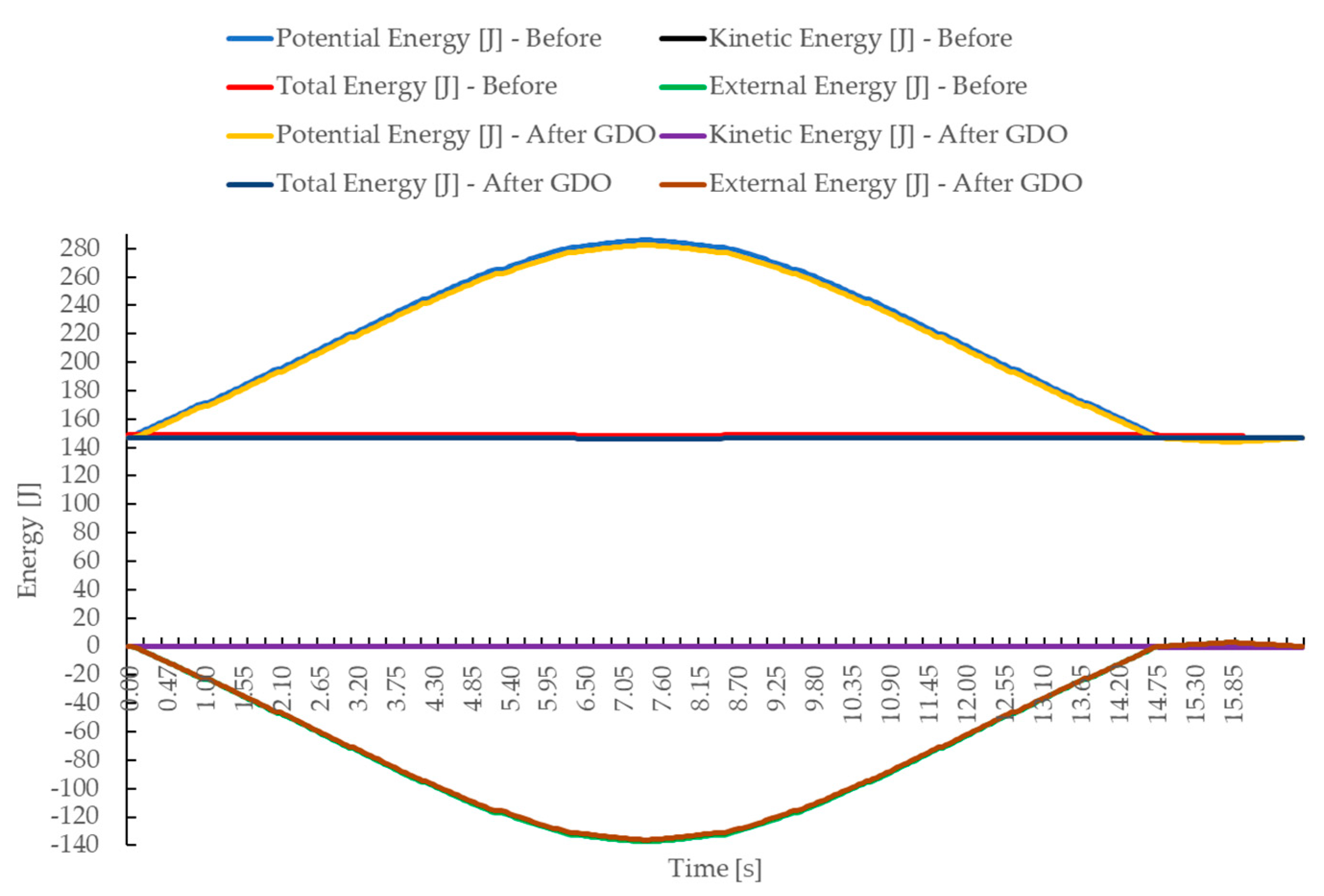
Figure 13.
Compare the potential, kinetic, total, and external energy of the positioning system of the CPM device before and after Generative Design optimisation.
Figure 13.
Compare the potential, kinetic, total, and external energy of the positioning system of the CPM device before and after Generative Design optimisation.
Figure 14.
Compare moments in the B’ kinematic pair of the positioning system of the CPM device before and after Generative Design optimisation.
Figure 14.
Compare moments in the B’ kinematic pair of the positioning system of the CPM device before and after Generative Design optimisation.
Table 1.
Summary of materials, masses, and loads of components of CPM device.
Table 1.
Summary of materials, masses, and loads of components of CPM device.
| Detail | Mass [kg] | Material |
|---|
| 1—link 1 | 0.61516 | 316 Stainless Steel |
| 2—link 2 | 0.63436 | 316 Stainless Steel |
| 3—link 3 | 0.81712 | Aluminium, 6061 |
| 4—link 4 | 0.89385 | Aluminium, 6061 |
| 5—link 5 | 0.61152 | Stainless steel, AISI 201 |
| 6—translation system 6 | 0.36466 | Stainless steel, 201 + Aluminium, 6061 |
| 7—thigh support + point mass | 0.1455 + 24.00 | Plastic, ABS |
| 8—calf support + point mass | 0.19186 + 10.70 | Plastic, ABS |
| 9—electrical linear drive | 2.24429 | Aluminium Alloy |
| 10—foot support + point mass | 1.2617 + 3.50 | Aluminium, 6061 |
| 11—delta robot link | 0.08714 | Stainless steel, 201 |
Table 2.
Material properties used in Generative Design simulation for links 3 and 4.
Table 2.
Material properties used in Generative Design simulation for links 3 and 4.
| Parameter | ALUMINIUM 6061 | MG AL ALLOY | MG AL ZN ALLOY |
|---|
| Density, [kg/m3] | 2710.2 | 1800 | 1800 |
| Young’s Modulus, [Pa] | 6.89476 × 10¹⁰ | 4.61 × 10¹⁰ | 4.5 × 10¹⁰ |
| Poisson’s Ratio | 0.3 | 0.357 | 0.305 |
| Yield Stress, [Pa] | 2.41 × 10⁸ | 1.44 × 10⁸ | 1.91 × 10⁸ |
| Shear Stiffness, [Pa] | 2.65183 × 10¹⁰ | 1.6986 × 10¹⁰ | 1.72414 × 10¹⁰ |
| Thermal Expansion, [1/K] | 2.34 × 10⁻⁵ | 2.58 × 10⁻⁵ | 2.74 × 10⁻⁵ |
| Conductivity, [W/(mK)] | 180.073 | 73.9 | 78 |
Table 3.
Material properties used in Generative Design simulation for links 1 and 2.
Table 3.
Material properties used in Generative Design simulation for links 1 and 2.
| Parameter | 316 STAINLESS STEEL |
|---|
| Density, [kg/m3] | 8000 |
| Young’s Modulus, [Pa] | 2.05 × 10⁸ |
| Poisson’s Ratio | 0.28 |
| Yield Stress, [Pa] | 2.9 × 10⁸ |
| Shear Stiffness, [Pa] | 7.37 × 10¹⁰ |
| Thermal Expansion, [1/K] | 2.34 × 10⁻⁵ |
| Conductivity, [W/(mK)] | 21.5 |
Table 4.
Results of Generative Design optimisation of link 3—material AL 6061.
Table 4.
Results of Generative Design optimisation of link 3—material AL 6061.
| Parameter | Limit Volume 20% | Limit Volume 30% | Limit Volume 40% | Limit Volume 50% |
|---|
| Starting mass, [kg] | 2.153 |
| Valid value, [%] | 14.9 | 26.9 | 38.3 | 50.2 |
| Parameters of link 3 after Generative Design optimisation |
| Displacement, [mm] | 6.038 | 2.48 | 1.7284 | 1.0884 |
| Von Mises Stress, [MPa] | 279.76 | 112.74 | 101.01 | 87.06 |
| Final mass, [kg] | 0.3210 | 0.5800 | 0.8240 | 1.0800 |
Table 5.
Results of Generative Design optimisation of link 3—material MG-AL-ZN ALLOY.
Table 5.
Results of Generative Design optimisation of link 3—material MG-AL-ZN ALLOY.
| Parameter | Limit Volume 20% | Limit Volume 30% | Limit Volume 40% | Limit Volume 50% |
|---|
| Starting mass, [kg] | 1.43 |
| Valid value, [%] | Not generated | 26.4 | 38.1 | 50.0 |
| Parameters of link 3 after Generative Design optimisation |
| Displacement, [mm] | - | 4.27 | 2.63 | 1.66 |
| Von Misses Stress, [MPa] | - | 100.83 | 100.94 | 86.97 |
| Final mass, [kg] | - | 0.3770 | 0.5440 | 0.7150 |
Table 6.
Results of Generative Design optimisation of link 3—material MG-AL ALLOY.
Table 6.
Results of Generative Design optimisation of link 3—material MG-AL ALLOY.
| Parameter | Limit Volume 20% | Limit Volume 30% | Limit Volume 40% | Limit Volume 50% |
|---|
| Starting mass, [kg] | 1.43 |
| Valid value, [%] | 15 | 27 | 37.6 | 50.0 |
| Parameters of link 3 after Generative Design optimisation |
| Displacement, [mm] | 7.3908 | 3.9095 | 2.336 | 1.662 |
| Von Mises Stress, [MPa] | 277.50 | 99.79 | 99.97 | 86.97 |
| Final mass, [kg] | 0.2140 | 0.3860 | 0.5380 | 0.7140 |
Table 7.
Results of Generative Design optimisation of link 4—material AL 6061.
Table 7.
Results of Generative Design optimisation of link 4—material AL 6061.
| Parameter | Limit Volume 20% | Limit Volume 30% | Limit Volume 40% | Limit Volume 50% |
|---|
| Starting mass, [kg] | 2.35 |
| Valid value, [%] | 14.2 | 25.1 | 36.5 | 49.3 |
| Parameters of link 4 after Generative Design optimisation |
| Displacement, [mm] | 4.0465 | 4.049 | 2.245 | 1.44 |
| Von Mises Stress, [MPa] | 318.18 | 201.21 | 202.60 | 203.03 |
| Final mass, [kg] | 0.3330 | 0.5900 | 0.8570 | 1.1550 |
Table 8.
Results of Generative Design optimisation of link 4—material MG-AL-ZN ALLOY.
Table 8.
Results of Generative Design optimisation of link 4—material MG-AL-ZN ALLOY.
| Parameter | Limit Volume 20% | Limit Volume 30% | Limit Volume 40% | Limit Volume 50% |
|---|
| Starting mass, [kg] | 1.561 |
| Valid value, [%] | 14.2 | 25.3 | 35.9 | 49.2 |
| Parameters of link 4 after Generative Design optimisation |
| Displacement, [mm] | 4.4611 | 5.14 | 3.24 | 2.21 |
| Von Mises Stress, [MPa] | 240.42 | 201.80 | 202.49 | 202.97 |
| Final mass, [kg] | 0.2210 | 0.3950 | 0.5600 | 0.7690 |
Table 9.
Results of Generative Design optimisation of link 4—material MG-AL ALLOY.
Table 9.
Results of Generative Design optimisation of link 4—material MG-AL ALLOY.
| Parameter | Limit Volume 20% | Limit Volume 30% | Limit Volume 40% | Limit Volume 50% |
|---|
| Starting mass, [kg] | 1.5611 |
| Valid value, [%] | 14.2 | 25.1 | 36.3 | 49.3 |
| Parameters of link 4 after Generative Design optimisation |
| Displacement, [mm] | 4.7928 | 6.1504 | 3.7318 | 2.1634 |
| Von Mises Stress, [MPa] | 249.96 | 201.12 | 202.90 | 203.02 |
| Final mass, [kg] | 0.2210 | 0.3910 | 0.5670 | 0.7696 |
Table 10.
Results of Generative Design optimisation of link 1—material 316 Stainless Steel.
Table 10.
Results of Generative Design optimisation of link 1—material 316 Stainless Steel.
| Parameter | Limit Volume <75% | Limit Volume 75% | Limit Volume 80% | Limit Volume 85% |
|---|
| Starting mass, [kg] | 0.61516 |
| Valid value, [%] | Not generated | 74.8 | 78.6 | 83.2 |
| Parameters of link 1 after Generative Design optimisation |
| Displacement, [mm] | - | 8.3405 × 10⁻⁴ | 8.3404 × 10⁻⁴ | 8.3400 × 10⁻⁴ |
| Von Mises Stress, [MPa] | - | 0.0285831 | 0.0285827 | 0.0285812 |
| Final mass, [kg] | - | 0.452 | 0.476 | 0.504 |
Table 11.
Results of Generative Design optimisation of links 2—material 316 Stainless Steel.
Table 11.
Results of Generative Design optimisation of links 2—material 316 Stainless Steel.
| Parameter | Limit Volume <90% | Limit Volume 90% |
|---|
| Starting mass, [kg] | 0.63436 |
| Valid value, [%] | Not generated | 86.2 |
| Parameters of link 2 after Generative Design optimisation |
| Displacement, [mm] | - | 1.45 × 10⁻³ |
| Von Mises Stress, [MPa] | - | 52.3150 |
| Final mass, [kg] | - | 0.538 |
Table 12.
The comparison of moment values in B’ kinematic pair of the CPM positioning system.
Table 12.
The comparison of moment values in B’ kinematic pair of the CPM positioning system.
| Moment | Value before GDO [Nm] | Value after GDO [Nm] |
|---|
| X-axis | 68.788 | 2.7136 |
| Y-axis | 1.0039 | 0.5566 |
| Z-axis | 59.215 | 58.587 |
| Total moment | 90.661 | 58.648 |


