Two-Way Power Flow Balancing in Three-Phase Three-Wire Networks by Unbalanced Capacitive Shunt Compensation
Abstract
:1. Introduction
- increasing the power transfer capacity of some lines (sections of lines), transformer substations or transformer stations;
- ensuring the technical conditions that allow for maximizing the energy generated by the distributed sources;
- ensuring the appropriate quality of power delivered to consumers by limiting the level of disturbances produced and propagated in the network (power frequency disturbances, electromagnetic interferences, transients, harmonics and low power factor, overvoltages, voltage fluctuations, voltage unbalances, etc. [1]).
- identification and analysis of unbalanced shunt capacitive compensation as a method of two-way power flow balancing in three-phase networks;
- demonstrating, based on the mathematical model, respectively, by numerical simulation, the ability of the BCC to extend its load balancing function as the two-way power flow balancing function in the controlled section;
- the conception and construction of the Simulink model, respectively, and the interpretation of the operating regimes numerical simulation results of a distribution network containing a high level of renewable distributed sources.
2. BCC—From Load Balancing to Power Flow Balancing
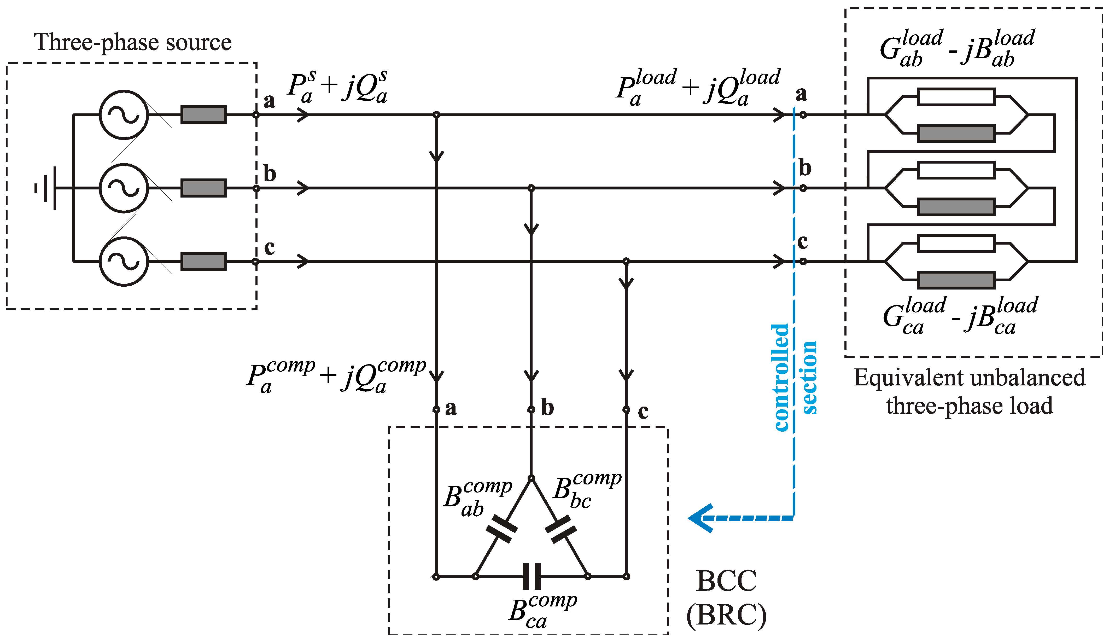
- depending on the values of the three equivalent susceptances of the load:
- depending on the reactive components of the currents on the load phases:
- depending on the reactive power components in the load phases:
- depending on the real and imaginary parts of the sequence components of the load currents:
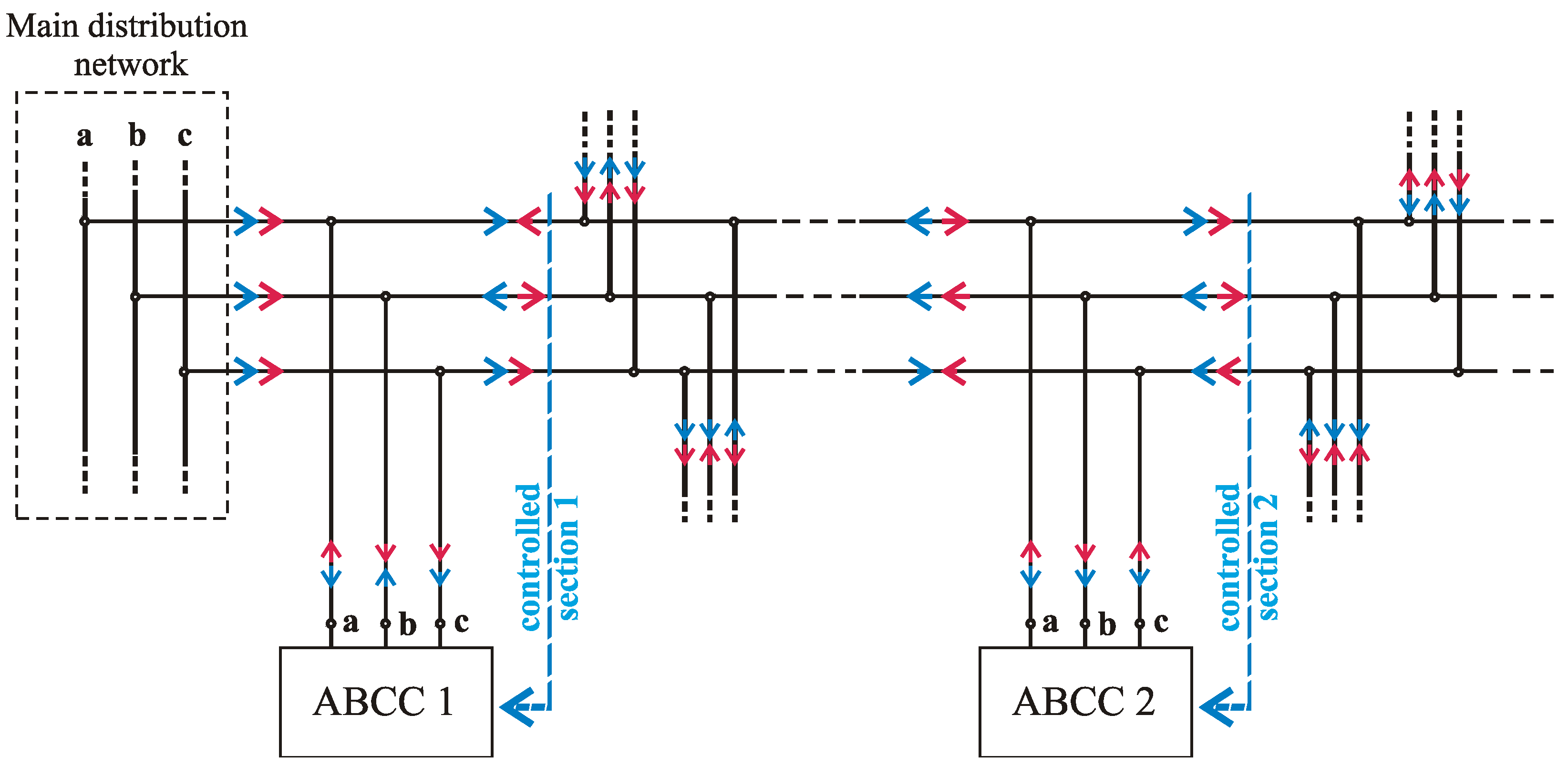
- reducing the asymmetry of the three-phase voltages;
- placing the rms voltage values at the consumer terminals within the admissible limits by reducing the maximum voltage losses on the phases;
- avoiding thermal overloading of the current paths on the network sections;
- reducing the level of unbalance disturbances transferred to the main network.
3. Power Flow Balancing in a Medium Voltage Distribution Network with a High Concentration of DERs (Case Study)
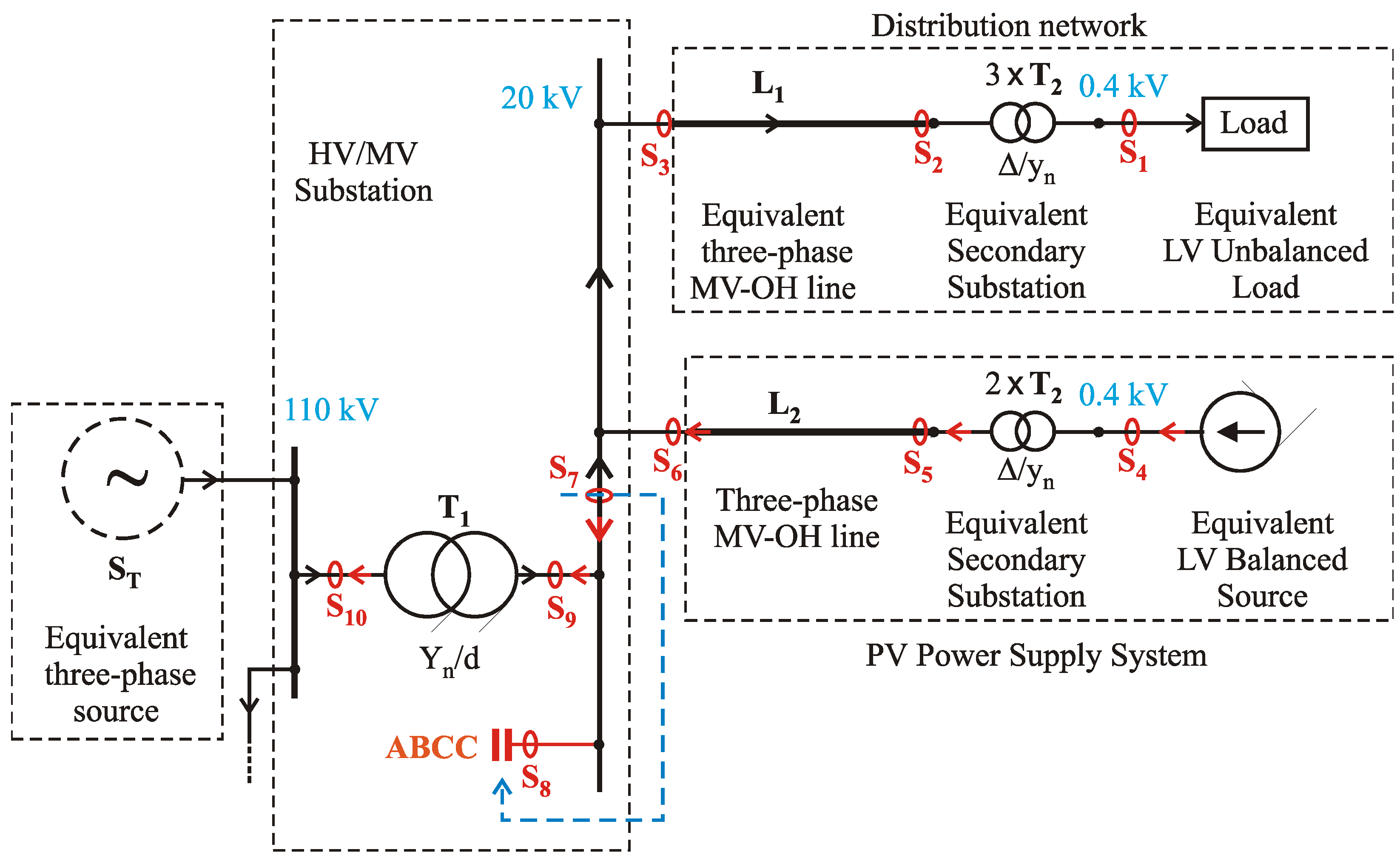
- an equivalent three-phase medium voltage overhead line;
- an equivalent transformer station MV/LV;
- an equivalent three-phase unbalanced load connected to LV.
- Regime 1—winter, morning load peak—the PV system generates a high-value active power, but less than the value of the active power consumed in the RED—the active power flows from the PV system to the MV RED
- Regime 2—summer, daytime no-load—the PV system generates a high-value active power, higher than the value of the active power consumed in the RED—the active power flows from the RED to the HV network.
- The zero-sequence components of currents and voltages appear only in the areas of three-phase four-wire circuits, more precisely in the secondaries of T2-type transformers, located at the low voltage level (sections S1 and S4). This observation is confirmation of the correctness of the modelling, knowing that the delta connection interrupts the propagation of the zero-sequence components of the currents.
- On the branch S1–S2–S3 the negative sequence components of the currents are propagated, the source of the asymmetry disturbance being the unbalanced load. There is no negative sequence current flow on the branch S4–S5–S6 and therefore the negative sequence components of the voltages are zero, as a result of the fact that the PV source is perfectly balanced. The current unbalance disturbance is also found in section S7, which is the section considered for the sizing (adjustment) of the capacitance values of the ABCC (controlled section).
- The power flow in the two regimes is completed in the presence of the ABCC, so that in section S9 and from the high voltage network S10, the assembly formed by ABCC (S8)—the distribution network (S7)—is seen as perfectly balanced, as a three-phase active power load (Regime 1) or as a three-phase active power source (Regime 2).
- Comparing the values of the active powers and the reactive powers from sections S7 and S8, the operation mode of the ABCC is found, also resulting from the mathematical model (10)–(16). Thus, in order to balance the active powers on each phase, ABCC takes over or delivers an active power whose value is equal to the algebraic difference of the active power on the respective phase of the controlled section S7, and the arithmetic mean of the values of the three active powers on the phases (confirmation of 12). On each phase of section S9 the values of active powers are equal to the arithmetic mean of the values of active powers in section S7 (confirmation of 14). For the compensation of the inductive-reactive power on the phases of the controlled section S7, ABCC absorbs from the network on each phase a capacitive-reactive power of the same value as the inductive-reactive power on the corresponding phase of the load (confirmation of 15). It can be said that the inductive-reactive power on each phase of the load is taken from the BCC so that the higher voltage network discharges the reactive power required to supply the load.
- On each phase of ABCC (S8), the value of the reactive power is negative, and it has a capacitive character, which seems natural. ABCC is a reactive power source. But it is not as natural as ABCC, although it is composed only of capacitors, to also intervene in the active power flow in the network. As can be seen from the simulation results, in some phases, it takes active power from the network and in others it feeds back active power to the network. The sum of the values of the active powers taken is equal to the sum of the active values delivered (confirmation of the 13). It can be said that ABCC makes a redistribution of the active power between the phases of the network until they are balanced. On the set of the three phases of the ABCC, the algebraic sum of the active powers is zero (confirmation of the 13).
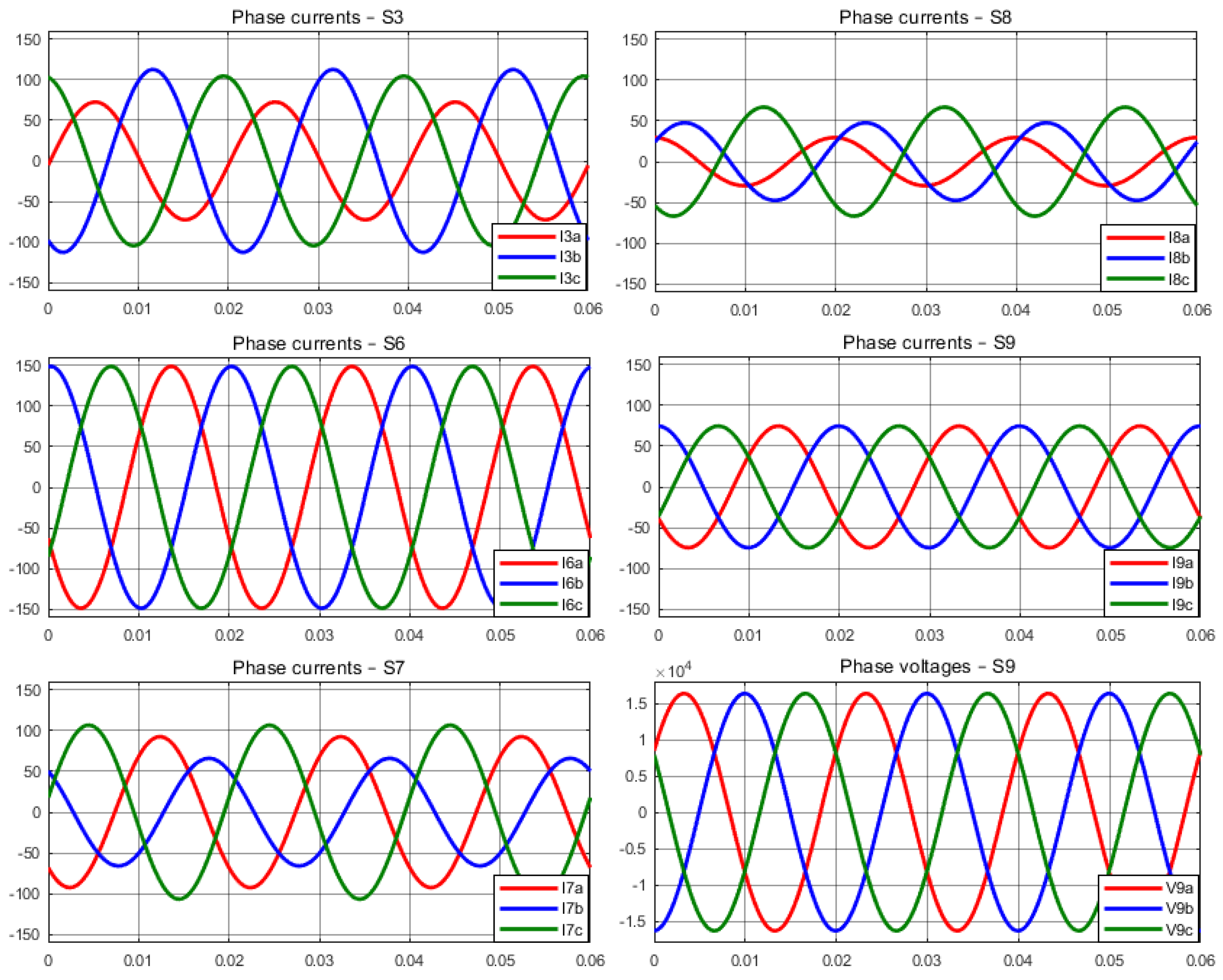
- The load balancing effect in the secondary of the T1 transformer in the HV/MV substation is also seen from the sequence current flow. Practically the negative sequence components of the currents in the controlled section S7 are equal in rms value and are in phase opposition to the negative sequence components of the currents on the ABCC phases (S8), compensating each other (confirmation of the 17 and 18). In sections S9 and S10 the currents have only positive sequence components (confirmation of the 19).
- In the presence of ABCC, a perfectly balanced three-phase equivalent load (Regime 1) or a perfectly balanced three-phase active power source (Regime 2) is “seen” in the secondary of the T1 transformer (S9), so that in all sections on the busbars of MV of the substation and on their derivations (S3, S6, S7, S8, S9), the voltages are perfectly symmetrical.
4. Conclusions
Author Contributions
Funding
Institutional Review Board Statement
Informed Consent Statement
Data Availability Statement
Conflicts of Interest
Abbreviations
| DER | Distributed Energy Resources |
| EPDS | Electric Power Distribution Systems |
| EV | Electric Vehicles |
| PCC | Point of Common Coupling |
| HV/MV/LV | High/Medium/Low Voltage |
| SPC | Switching Power Converter |
| LVR | Line Voltage Regulator |
| OLTC | On-Load Tap Changer |
| RPC | Reactive Power Compensator |
| ZSCC | Zero Sequence Current Compensator |
| D-STATCOM | Distribution Static Synchronous Compensator |
| DVR | Dynamic Voltage Restorer |
| UPQC | Unified Power Quality Conditioner |
| BESS | Battery Energy Storage System |
| PV | Photo Voltaic |
| BRC | Balancing Reactive Compensator |
| ABC | Adaptive Balancing Compensator |
| SVC | Static var Compensator |
| CPC | Current’s Physical Components |
| BCC | Balancing Capacitive Compensator |
| ABCC | Adaptive Balancing Capacitive Compensator |
Notations
| U, a | phase to ground rms voltage, Stokvis’ rotation operator |
| equivalent admittances of the load in the delta equivalent scheme | |
| equivalent conductances of the load in the delta equivalent scheme | |
| equivalent susceptances of the load in the delta equivalent scheme | |
| phasors of positive, negative and zero sequence components of the phase currents at the three-phase unbalanced load | |
| phasors of positive, negative and zero sequence components of the phase currents at BCC | |
| phasors of positive, negative and zero sequence components of the phase currents at three-phase source | |
| power factor on the positive sequence | |
| the equivalent susceptances on the sides of the delta scheme of the compensator | |
| the reactive components of the currents on the load phases; | |
| reactive powers on the load phases | |
| active powers on the load phases | |
| active powers on the BCC phases | |
| the arithmetic mean value of the active powers on the load phases | |
| active powers on the source phases | |
| reactive powers on the load phases | |
| total, respectively average reactive powers of the load | |
| reactive powers on the BCC phases | |
| reactive powers on the source phases | |
| phasors of the phase currents at the three-phase unbalanced load | |
| phasors of the phase currents at BCC | |
| phasors of the phase currents at three-phase source | |
| proportionality factor applied to supplement the capacitive compensation on the positive sequence |
References
- Khadem, S.K.; Basu, M.; Conlon, M.F. Power quality in grid connected renewable energy systems: Role of custom power devices. In Proceedings of the Conference on Renewable Energies and Power Quality (ICREPQ’10), Granada, Spain, 23–25 March 2010. [Google Scholar]
- Pudjianto, D.; Strbac, G.; Boyer, D. Virtual power plant: Managing synergies and conflicts between transmission system operator and distribution system operator control objectives. CIRED Open Access Proc. J. 2017, 2017, 2049–2052. [Google Scholar] [CrossRef]
- Soltani, S.H.; Rashidinejad, M.; Abdollahi, A. Dynamic phase balancing in the smart distribution networks. Int. J. Electr. Power Energy Syst. 2017, 93, 374–383. [Google Scholar] [CrossRef]
- Pratama, N.A.; Rahmawati, Y. Evaluation of unbalanced load impacts on distribution transformer performances. Front. Energy Syst. Power Eng. 2020, 2, 28–35. [Google Scholar]
- Njafi, A.; Iskender, I.; Genc, N. Evaluating and derating of three-phase distribution transformer under unbalanced voltage and unbalance load using finite element method. In Proceedings of the 2014 IEEE 8th International Power Engineering and Optimization Conference (PEOCO2014), Langkawi, Malaysia, 24–25 March 2014. [Google Scholar]
- Kersting, W.H. Causes and effects of unbalanced voltages serving an induction motor. IEEE Trans. Ind. Appl. 2001, 37, 165–170. [Google Scholar] [CrossRef]
- Bossio, G.R.; De Angelo, C.H.; Donolo, P.D.; Castellino, A.M.; Garcia, G.O. Effects of voltage unbalance on IM power, torque and vibrations. In Proceedings of the 2009 IEEE International Symposium on Diagnostics for Electric Machines, Power Electronics and Drives, Cargese, France, 31 August–3 September 2009. [Google Scholar]
- Kongtrakul, N.; Wangdee, W.; Chantaraskul, S. Comprehensive review and a novel technique on voltage unbalance compensation. IET Smart Grid 2023, 6, 331–358. [Google Scholar] [CrossRef]
- Jahn, R.; Holt, M.; Rehtanz, C. Mitigation of voltage unbalances using a line voltage regulator. In Proceedings of the 2021 IEEE Madrid Power-Tech, Madrid, Spain, 28 June–2 July 2021. [Google Scholar]
- Zecchino, A.; Hu, J.; Coppo, M.; Marinelli, M. Experimental testing and model validation of a decoupled-phase on-load tap-changer transformer in an active network. IET Gener. Transm. Distrib. 2016, 10, 3834–3843. [Google Scholar] [CrossRef]
- Czarnecki, L.S.; Haley, P.M. Unbalanced power in four-wire systems and its reactive compensation. IEEE Trans. Power Deliv. 2015, 30, 53–63. [Google Scholar] [CrossRef]
- Montoya-Mira, R.; Blasco, P.A.; Diez, J.M.; Montoya, R.; Reig, M.J. Unbalanced and Reactive Currents Compensation in Three-Phase Four-Wire Sinusoidal Power Systems. Appl. Sci. 2020, 10, 1764. [Google Scholar] [CrossRef]
- Chang, W.N.; Yeh, K.D. Real-time load balancing and power factor correction of three-phase, four-wire unbalanced systems with DSTATCOM. J. Mar. Sci. Technol. 2014, 22, 8. [Google Scholar]
- Subramani, M.B.; Gulipalli, S.C.; Chu, C.C. An improved compensation technique using DVR for power quality improvement in distribution power system. In Proceedings of the 2021 IEEE 2nd International Conference on Smart Technologies for Power, Energy and Control (STPEC), Bilaspur, India, 19–22 December 2021. [Google Scholar]
- Abdoli, O.; Gholipour, E.; Hooshmand, R.A. A new approach to compensating voltage unbalance by UPQC-based PAC. Elec. Power Compon. Syst. 2018, 46, 1769–1781. [Google Scholar] [CrossRef]
- Coppo, M.; Raciti, A.; Caldon, R.; Turri, R. Exploiting inverter-interfaced DG for voltage unbalance mitigation and ancillary services in distribution systems. In Proceedings of the 2015 IEEE 1st International Forum on Research and Technologies for Society and Industry Leveraging a better tomorrow (RTSI), Turin, Italy, 16–18 September 2015. [Google Scholar]
- Nejabatkhah, F.; Li, Y.W. Flexible unbalanced compensation of three phase distribution system using single-phase distributed generation inverters. IEEE Trans. Smart Grid 2019, 10, 1845–1857. [Google Scholar] [CrossRef]
- Weckx, S.; Driesen, J. Load balancing with EV chargers and PV inverters in unbalanced distribution grids. IEEE Trans. Sustain. Energy 2015, 6, 635–643. [Google Scholar] [CrossRef]
- Islam, M.R.; Lu, H.; Hossain, M.J.; Li, L. Mitigating unbalance using distributed network reconfiguration techniques in distributed power generation grids with services for electric vehicles: A review. J. Clean. Prod. 2019, 239, 117932. [Google Scholar] [CrossRef]
- Shahania, F.; Wolfs, P.J.; Ghosh, A. Voltage unbalance reduction in low voltage feeders by dynamic switching of residential customers among three phases. IEEE Trans. Smart Grid 2014, 5, 1318–1327. [Google Scholar] [CrossRef]
- Islam, M.R.; Lu, H.; Hossain, M.J.; Li, L. Optimal coordination of electric vehicles and distributed generators for voltage unbalance and neutral current compensation. IEEE Trans. Ind. Appl. 2021, 57, 1069–1080. [Google Scholar] [CrossRef]
- Siti, M.W.; Nicolae, D.V.; Jimoh, A.A.; Ukil, A. Reconfiguration and load balancing in the LV and MV distribution networks for optimal performance. IEEE Trans. Power Deliv. 2007, 22, 2534–2540. [Google Scholar] [CrossRef]
- Gyugyi, L.; Otto, R.; Putman, T. Principles and applications of static thyristor-controlled shunt compensators. IEEE Trans. Power Appl. Syst. 1978, PAS-97, 1935–1945. [Google Scholar]
- Gueth, G.; Enstedt, P.; Rey, A.; Menzies, R.W. Individual phase control of a static compensator for load compensation and voltage balancing. IEEE Power Eng. Rev. 1987, 2, 898–905. [Google Scholar]
- Czarnecki, L.S.; Hsu, S.M.; Chen, G. Adaptive balancing compensator. IEEE Trans. Power Deliv. 1995, 10, 1663–1669. [Google Scholar] [CrossRef]
- Pană, A. Active load balancing in a three-phase network by reactive power compensation. In Power Quality—Monitoring, Analysis and Enhancement; Zobaa, A., Ed.; InTech: Rijeka, Croatia, 2011; pp. 219–254. [Google Scholar]
- Chang, W.N.; Liao, C.H. Design and implementation of a STATCOM based on a multilevel FHB converter with delta-connected configuration for unbalanced load compensation. Energies 2017, 10, 921. [Google Scholar] [CrossRef]
- Barrios-Martínez, E.; Ángeles-Camacho, C. Technical comparison of FACTS controllers in parallel connection. J. Appl. Res. Technol. 2017, 15, 36–44. [Google Scholar] [CrossRef]
- Pană, A.; Băloi, A.; Molnar-Matei, F. Load balancing by unbalanced capacitive shunt compensation—A numerical approach. In Proceedings of the 2010 14th International Conference on Harmonics and Quality of Power (ICHQP 2010), Bergamo, Italy, 26–29 September 2010. [Google Scholar]
- Pană, A.; Băloi, A.; Molnar-Matei, F. From the balancing reactive compensator to the balancing capacitive compensator. Energies 2018, 11, 1979. [Google Scholar] [CrossRef]
- Pană, A.; Băloi, A.; Molnar-Matei, F. New method for calculating the susceptances of a balancing capacitive compensator for a three-phase four-wire distribution network. Int. J. Electr. Power Energy Syst. 2020, 115, 105414. [Google Scholar] [CrossRef]


| Operating Regime | The Values of the Shunt Equivalent Parameters | |
|---|---|---|
| Regime 1 | ||
| Regime 2 | ||
| Operating Regime | The Values of the Equivalent Current Source’s Parameters | |
|---|---|---|
| Regime 1 and Regime 2 | , | , , , |
| Capacitance | Regime 1 | Regime 2 |
|---|---|---|
| Cab | 7.371 µF | 0.0728 µF |
| Cbc | 8.083 µF | 5.3075 µF |
| Cca | 1.465 µF | 3.2753 µF |
| Electrical Quantity | S1 | S2 | S3 | S4 | S5 | S6 | S7 | S8 | S9 | S10 | |
|---|---|---|---|---|---|---|---|---|---|---|---|
| Pa [kW] | 1963.78 | 1984.71 | 2091.7 | −1248.86 | −1235.2 | −1203.3 | 888.4 | −234.98 | 653.41 | 690.87 | |
| Pb [kW] | 1492.8 | 1777.36 | 1885.04 | −1248.88 | −1235.2 | −1203.3 | 681.74 | −28.32 | 653.41 | 690.87 | |
| Pc [kW] | 1769.88 | 1525.13 | 1593.4 | −1248.88 | −1235.2 | −1203.3 | 390.1 | 263.31 | 653.41 | 690.87 | |
| ΣP [kW] | 5226.48 | 5287.2 | 5570.14 | −3746.62 | −3705.6 | −3609.9 | 1960.24 | ≈0 | 1960.23 | 2072.61 | |
| Qa [kvar] | 687.32 | 615.18 | 685.8 | −174.57 | −105.03 | −76.78 | 609.01 | −608.92 | 0.088 | 51.63 | |
| Qb [kvar] | 895.7 | 1070.28 | 1141.8 | −174.56 | −105.03 | −76.78 | 1065.09 | −1065.00 | 0.088 | 51.63 | |
| Qc [kvar] | 416.43 | 704.92 | 734.87 | −174.59 | −105.03 | −76.78 | 658.08 | −657.99 | 0.087 | 51.63 | |
| ΣQ [kvar] | 1999.45 | 2390.38 | 2562.47 | −523.72 | −315.09 | −230.34 | 2332.18 | −2331.91 | 0.2645 | 154.89 | |
| I+ [A] | 8130 | 170.4 | 169 | 5268 | 99.68 | 99.71 | 83.98 | 64.28 | 54.03 | 10.91 | |
| I− | [A] (%) | 1138 (13.99) | 23.89 (14.02) | 23.91 (14.14) | 0.006 (≈0) | 0 (0) | 0 (0) | 23.91 (28.47) | 23.91 (37.19) | 0 (0) | 0 (0) |
| I0 | [A] (%) | 175.3 (2.15) | 0 (0) | 0 (0) | 0 (0) | 0 (0) | 0 (0) | 0 (0) | 0 (0) | 0 (0) | 0 (0) |
| Ua [V] | 227.9 | 11,349.3 | 12,093.01 | 239.37 | 12,436.87 | 12,093.01 | 63,485.38 | ||||
| Ub [V] | 229.44 | 11,273.49 | 12,093.01 | 239.37 | 12,436.87 | 12,093.01 | 63,485.38 | ||||
| Uc [V] | 234.67 | 11,463.78 | 12,093.01 | 239.37 | 12,436.87 | 12,093.01 | 63,485.38 | ||||
| U+ [V] | 230.7 | 11,361.92 | 12,093.01 | 239.4 | 12,436.87 | 12,093.01 | 63,485.38 | ||||
| U− | [V] (%) | 4.29 (1.86) | 110.7 (9.74) | 0.013 (0) | 0 (0) | 0.014 (≈0) | 0.013 (≈0) | 0.07 (0) | |||
| U0 | [V] (%) | 0.33 (0.14) | 0 (0) | 0 (0) | 0 (0) | 0 (0) | 0 (0) | 0 (0) | |||
| Electrical Quantity | S1 | S2 | S3 | S4 | S5 | S6 | S7 | S8 | S9 | S10 | |
|---|---|---|---|---|---|---|---|---|---|---|---|
| Pa [kW] | 652.5 | 472.63 | 481.36 | −1255.24 | −1240.98 | 116.27 | −724.24 | 116.27 | −607.97 | −570.57 | |
| Pb [kW] | 688.1 | 766.88 | 787.58 | −1255.24 | −1240.98 | −190.05 | −418.03 | −190.05 | −608.08 | −570.67 | |
| Pc [kW] | 388.1 | 505.73 | 523.84 | −1255.27 | −1240.98 | 73.78 | −681.77 | 73.78 | −608.00 | −570.68 | |
| ΣP [kW] | 1728.7 | 1745.24 | 1792.78 | −3765.75 | −3722.96 | ≈0 | −1824.04 | ≈0 | −1824.05 | −1711.94 | |
| Qa [kvar] | 326.25 | 372.58 | 342.97 | −240.74 | −164.5 | −210.54 | 210.66 | −210.54 | 0.12 | 48.22 | |
| Qb [kvar] | 625.54 | 487.47 | 470.72 | −240.76 | −154.5 | −338.34 | 338.41 | −338.34 | 0.07 | 48.29 | |
| Qc [kvar] | 526.71 | 691.54 | 672.03 | −240.82 | −164.5 | −539.73 | 539.73 | −539.73 | 0.002 | 48.17 | |
| ΣQ [kvar] | 1478.5 | 1551.59 | 1485.72 | −722.32 | −493.5 | −1088.61 | 1088.8 | −1088.61 | 0.192 | 144.68 | |
| I+ [A] | 3454 | 69.38 | 67.19 | 5268 | 104.9 | 105 | 61.3 | 31.41 | 52.63 | 9.017 | |
| I− | [A] (%) | 828.9 (23.99) | 16.57 (23.88) | 16.58 (24.67) | 0 (0) | 0 (0) | 0 (0) | 16.58 (27.04) | 16.59 (52.81) | 0.006 (≈0) | 0.001 (≈0) |
| I0 | [A] (%) | 20.55 (0.6) | 0 (0) | 0 (0) | 0 (0) | 0 (0) | 0 (0) | 0 (0) | 0 (0) | 0 (0) | 0 (0) |
| Ua [V] | 222.05 | 11,313.37 | 11,551.88 | 242.62 | 11,928.58 | 11,551.88 | 63,510.11 | ||||
| Ub [V] | 217.42 | 11,191.71 | 11,551.9 | 242.63 | 11,928.61 | 11,551.9 | 63,510.1 | ||||
| Uc [V] | 211.09 | 11,206.5 | 11,551.93 | 242.63 | 11,928.63 | 11,551.93 | 63,510.13 | ||||
| U+ [V] | 220.2 | 11,237.06 | 11,551.9 | 242.6 | 11,928.61 | 11,551.9 | 63,510.1 | ||||
| U− | [V] (%) | 2.83 (1.28) | 76.78 (0.68) | 0.03 (≈0) | 0 (0) | 0 (0) | 0.03 (≈0) | 0.01 (≈0) | |||
| U0 | [V] (%) | 0.035 (≈0) | 0 (0) | 0 (0) | 0 (0) | 0 (0) | 0 (0) | 0 (0) | |||
Disclaimer/Publisher’s Note: The statements, opinions and data contained in all publications are solely those of the individual author(s) and contributor(s) and not of MDPI and/or the editor(s). MDPI and/or the editor(s) disclaim responsibility for any injury to people or property resulting from any ideas, methods, instructions or products referred to in the content. |
© 2024 by the authors. Licensee MDPI, Basel, Switzerland. This article is an open access article distributed under the terms and conditions of the Creative Commons Attribution (CC BY) license (https://creativecommons.org/licenses/by/4.0/).
Share and Cite
Pană, A.; Băloi, A.; Molnar-Matei, F.; Stănese, C.; Jorza, A.; Stoica, D. Two-Way Power Flow Balancing in Three-Phase Three-Wire Networks by Unbalanced Capacitive Shunt Compensation. Appl. Sci. 2024, 14, 3746. https://doi.org/10.3390/app14093746
Pană A, Băloi A, Molnar-Matei F, Stănese C, Jorza A, Stoica D. Two-Way Power Flow Balancing in Three-Phase Three-Wire Networks by Unbalanced Capacitive Shunt Compensation. Applied Sciences. 2024; 14(9):3746. https://doi.org/10.3390/app14093746
Chicago/Turabian StylePană, Adrian, Alexandru Băloi, Florin Molnar-Matei, Cristian Stănese, Andrei Jorza, and David Stoica. 2024. "Two-Way Power Flow Balancing in Three-Phase Three-Wire Networks by Unbalanced Capacitive Shunt Compensation" Applied Sciences 14, no. 9: 3746. https://doi.org/10.3390/app14093746


