Optical Current Sensors for High Power Systems: A Review


Abstract
:1. Introduction
- Immunity against electromagnetic interferences (EMI);
- Electrical isolation (the optical sensors are made of dielectric materials);
- Possibility for measuring AC and DC;
- Absence of saturation effects;
- Low power consumption;
- Small size, lightweight, and relatively low cost.
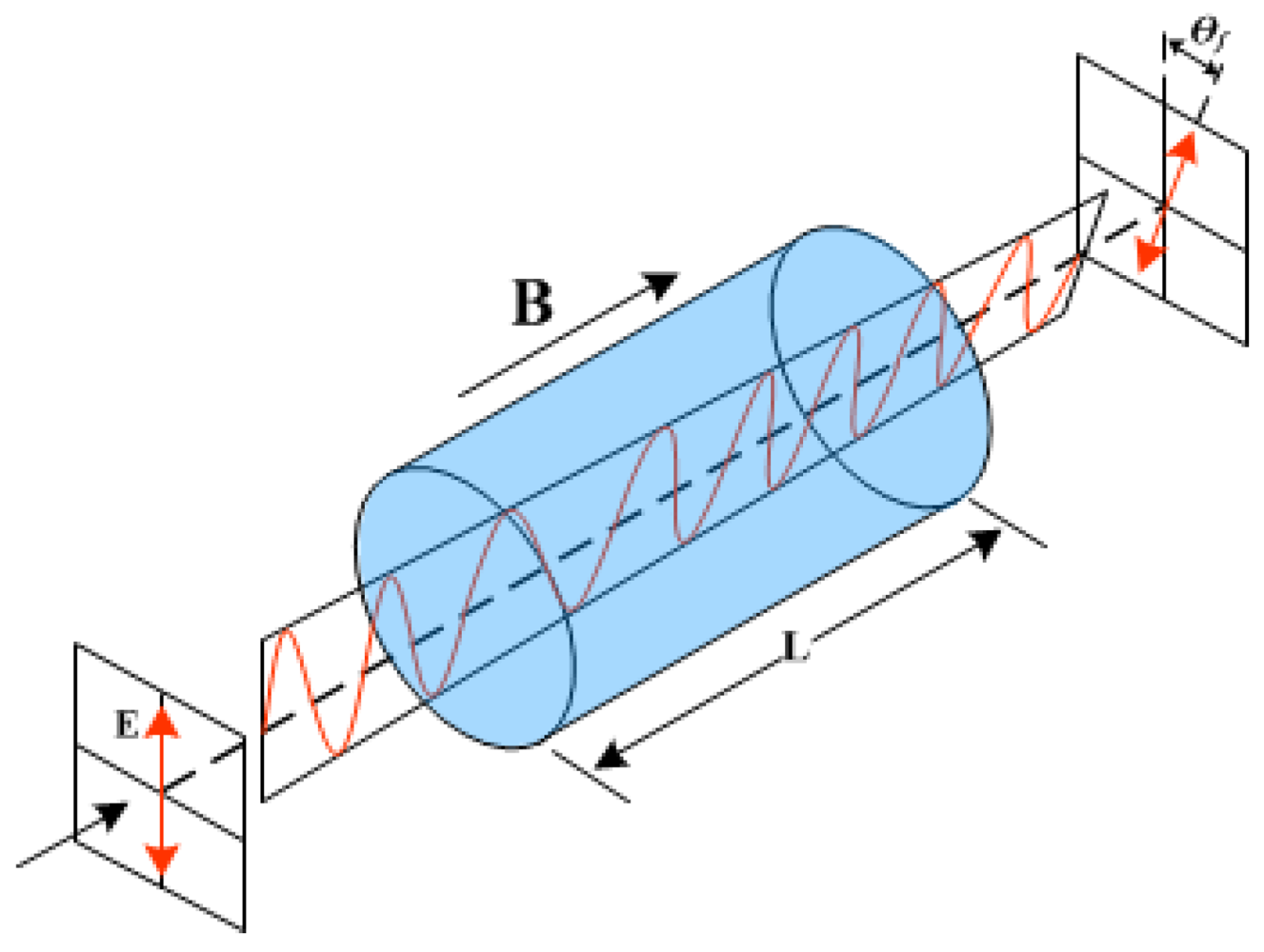
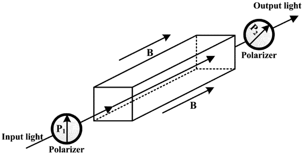
2. Faraday Effect
 (1)
(1)
3. Interrogation Techniques
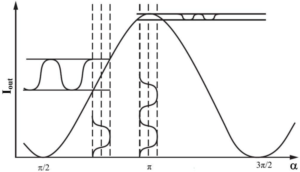
3.1. Polarimetric Detection
3.1.1. Basic Polarimetric Scheme
 (2)
(2)
 (3)
(3) (4)
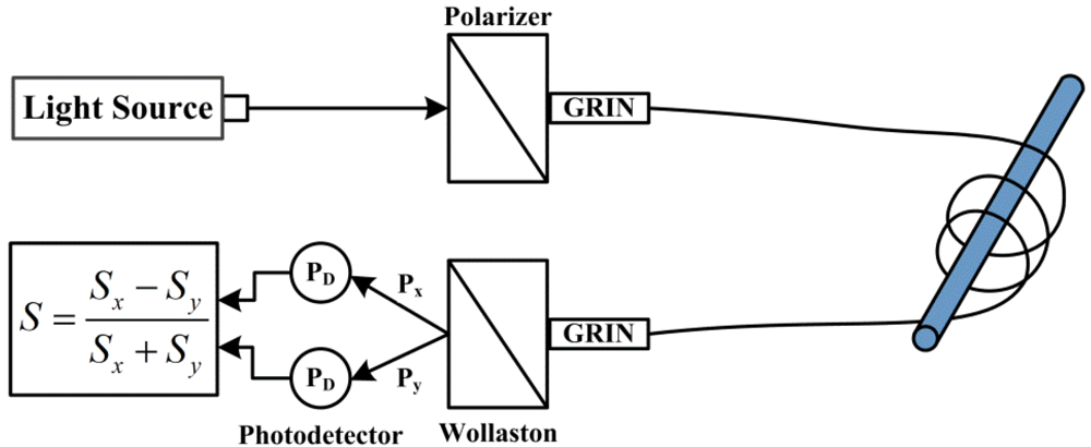
(4)3.1.2. Dual Quadrature Scheme

 (5)
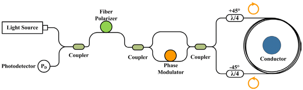
(5)3.2. Interferometric Detection Schemes


4. State of Art
- All-fiber sensor: The fiber itself acts as a transducer mechanism. The magneto-optical effect (or Faraday effect) is used to induce a rotation in the angle of polarization of the light propagating in the fiber, which is proportional to the magnetic field. Usually, the fiber is coiled around the electrical conductor, making it immune to external currents and magnetic fields.
- Bulk optic sensor: These sensors use a piece of glass or crystal with high Verdet constant as the transducer, which is placed near (or around) the electrical conductor. The magnetic field is also measured using the magneto-optical effect. These sensors are usually cheap, robust and more sensitive.
- Magnetic force sensors: In an analogous process to the piezoelectric elements, when a magnetic field is applied to a magnetostrictive element it induces mechanical changes in the material. These changes can be again measured by attaching a fiber Bragg grating (FBG) to the magnetostrictive element.
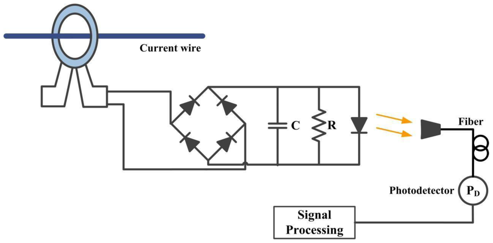
- Hybrid sensors: These sensors employ some of the standard electromagnetic technology already existent and some of optical technology. In this case, the first current transducer is done with conventional electromagnetic technology (such as, a Rogowski coil) but its interrogation and information transportation is done by an optical fiber system. The objective of these sensors is to construct an interrogation system that takes advantages of the high level of electrical isolation offered by optical fibers and avoids difficulties associated with birefringence.
4.1. All-Fiber Sensors
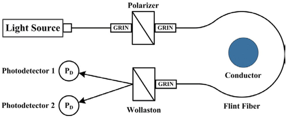

4.2. Bulk-Optic Current Sensors

4.3. Magnetic Force Sensors
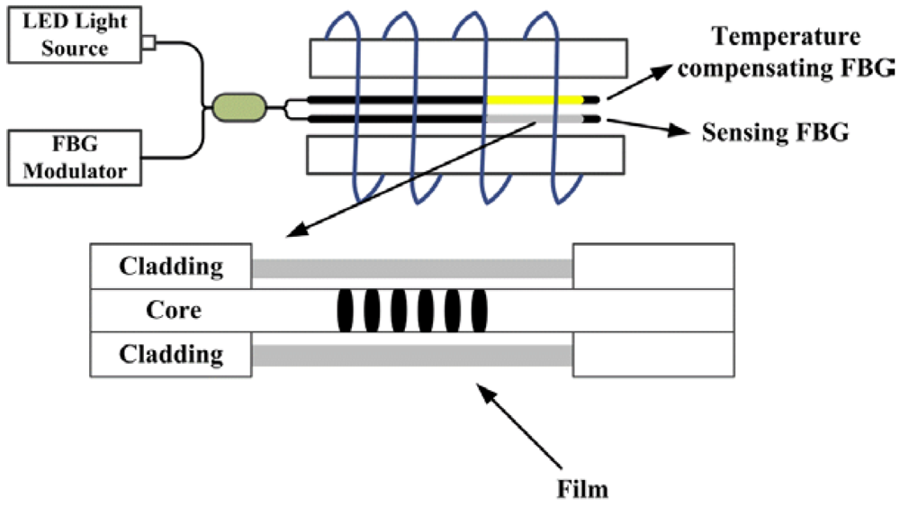
4.3.1. Magnetostrictive Sensors

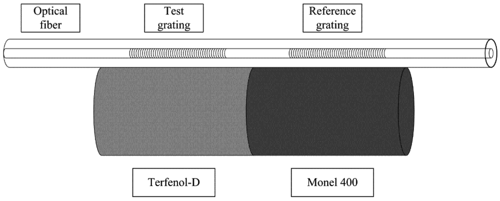
4.3.2. Terfenol‑D


4.3.3. Magnetic Fluid
4.4. Hybrid Sensors
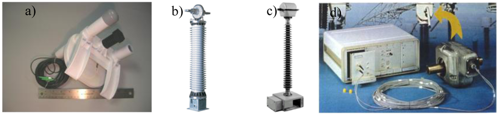
5. Commercially Available Prototypes
6. Conclusions
References
- Ning, Y.N.; Wang, Z.P. Recent progress in optical current sensing techniques. Rev. Sci. Instrum. 1995, 66, 3097–3111. [Google Scholar] [CrossRef]
- Hecht, E. Optics, 4th ed; Fundação Calouste Gulbenkian: San Francisco, CA, USA, 2002; pp. 325–368. [Google Scholar]
- Jorge, P. Sensores Ópticos para a Medição de Corrente Elétrica em Alta-tensão. Master Thesis, Faculdade de Ciências da Universidade do Porto, Porto, Portugal, 2001. [Google Scholar]
- Blake, J.; Tantaswadi, P.; Carvalho, R. In-line sagnac interferometer current sensor. IEEE Trans. Power Delivery 1996, 11, 116–121. [Google Scholar] [CrossRef]
- Jackson, D.A. An optical system with potential for remote health monitoring of subsea machinery. Meas. Sci. Technol. 2009, 20, 1–8. [Google Scholar]
- Perciante, C.D.; Ferrari, J.A. Magnetic crosstalk minimization in optical current sensors. IEEE Trans. Instrum. Meas. 2008, 57, 2304–2308. [Google Scholar] [CrossRef]
- Kurosawa, K.; Sakamoto, K.; Yoshida, S. Polarization-Maintaining Properties of the Flint Glass-Fiber for the Faraday Sensor Element. In Tenth International Conference on Optical Fiber Sensors, Glasgow, Scotland, 11 October 1994; pp. 28–35.
- Yamashita, T.; Watabe, A.; Masuda, I.; Sakamoto, K.; Kurosawa, K.; Yoshida, S. Extremely Small Stress-Optic Coefficient Glass Single Mode Fibers for Current Sensor. In Optical Fiber Sensors 11, Japan, 21 May 1996; pp. 168–171.
- Kurosawa, K. Optical current transducers using flint glass fiber as the Faraday sensor element. Opt. Rev. 1997, 4, 38–44. [Google Scholar] [CrossRef]
- Hotate, K.; Thai, B.T.; Saida, T. Comparison between Flint Glass Fiber and Twisted/Bent Single-Mode Fiber as a Faraday Element in an Interferometric Fiber Optic Current Sensor. In European Workshop on Optical Fibre Sensors, Scotland, 8 July 1998; pp. 233–237.
- Barczak, K.; Pustelny, T.; Dorosz, D.; Dorosz, J. New optical glasses with high refractive indices for applications in optical current sensors. Acta Phys. Pol. A 2009, 116, 247–249. [Google Scholar]
- Sun, L.; Jiang, S.; Zuegel, J.D.; Marciante, J.R. Effective verdet constant in terbium-doped-core. Opt. Lett. 2009, 34, 1699–1701. [Google Scholar] [CrossRef]
- Sun, L.; Jiang, S.; Marciante, J.R. Compact all-fiber optical Faraday components using 65-wt%-terbium-doped fiber with a record Verdet constant of −32 rad/(Tm). Opt. Express 2010, 18, 12191–12196. [Google Scholar]
- Rose, A.H.; Ren, Z.B.; Day, G.W. Twisting and annealing optical fiber for current sensors. J. Lightwave Technol. 1996, 14, 2492–2498. [Google Scholar] [CrossRef]
- Laming, R.I.; Payne, D.N. Electric-current sensors employing spun highly birefringent optical fibers. J. Lightwave Technol. 1989, 7, 2084–2094. [Google Scholar] [CrossRef]
- Bohnert, K.; Gabus, P.; Brandle, H. Towards commercial use of optical fiber current sensors. In Conference on Lasers and Electro-Optics (CLEO 2000), San Francisco, CA, USA, 7–12 May 2000; pp. 303–304.
- Tang, D.; Rose, A.H.; Day, G.W.; Etzel, S.M. Annealing of linear birefringence in single-mode fiber coils—Application to optical fiber current sensors. J. Lightwave Technol. 1991, 9, 1031–1037. [Google Scholar] [CrossRef]
- Rose, A.H.; Etzel, S.M.; Wang, C.M. Verdet constant dispersion in annealed optical fiber current sensors. J. Lightwave Technol. 1997, 15, 803–807. [Google Scholar] [CrossRef]
- Drexler, P.; Fiala, P. Utilization of Faraday mirror in fiber optic current sensors. Radioengineering 2008, 17, 101–107. [Google Scholar]
- Zhou, S.; Zhang, X. Simulation of linear birefringence reduction in fiberoptical current sensor. IEEE Photon. Technol. Lett. 2007, 19, 1568–1570. [Google Scholar] [CrossRef]
- Kurosawa, K.; Yamashita, K.; Sowa, T.; Yamada, Y. Flexible fiber faraday effect current sensor using flint glass fiber and reflection scheme. IEICE Trans. Electron. 2000, 83, 326–330. [Google Scholar]
- Bohnert, K.; Philippe, G.; Hubert, B.; Guggenbach, P. Highly accurate fiber-optic DC current sensor for the electrowinning industry. IEEE Trans. Ind. Appl. Mag. 2005, 43, 180–187. [Google Scholar]
- Zimmermann, A.C.; Besen, M.; Encinas, L.S.; Nicolodi, R. Improving Optical Fiber Current Sensor Accuracy using Artificial Neural Networks to Compensate Temperature and Minor Non-Ideal Effects. In the 21st International Conference on Optical Fiber Sensors, Ottawa, Canada, 21 May 2011; pp. 77535–448.
- The ABB Group—Automation and Power Technologies. Available online: http://www.abb.com/ (accessed on 14 December 2011).
- Rahmatian, F.; Blake, J.N. Applications of high-voltage fiber optic current sensors. In IEEE Power Engineering Society General Meeting; Montreal, Canada: 18 June 2006; pp. 1–6.
- Alstom Grid. Available online: http://www.nxtphase.com/ (accessed on 12 Dezember 2011).
- Ripka, P. Electric current sensors: A review. Meas. Sci. Technol. 2010, 21, 1–23. [Google Scholar]
- Walsey, G.A.; Fisher, N.E. Control of the Critical Angle of Reflection in an Optical Current Sensor. In Optical Fiber Sensors 12, Williamburg, VA, USA, 28 October 1997; pp. 237–240.
- Bush, S.P.; Jackson, D.A. Numerical investigations of the effects of birefringence and total internal reflection on Faraday effect current sensors. Appl. Opt. 1992, 31, 5366–5374. [Google Scholar] [CrossRef]
- Sato, T.; Takahashi, G.T.; Inui, Y. Method and apparatus for optically measuring a current. 4564754, 1986. [Google Scholar]
- Fisher, N.E.; Jackson, D.A. Vibration immunity and Ampere’s circuital law for a near perfect triangular Faraday current sensor. Meas. Sci. Technol. 1996, 7, 1099–1102. [Google Scholar] [CrossRef]
- Yi, B.; Chu, B.; Chiang, K.S. Magneto-optical electric-current sensor with enhanced sensitivity. Meas. Sci. Technol. 2002, 13, N61–N63. [Google Scholar] [CrossRef]
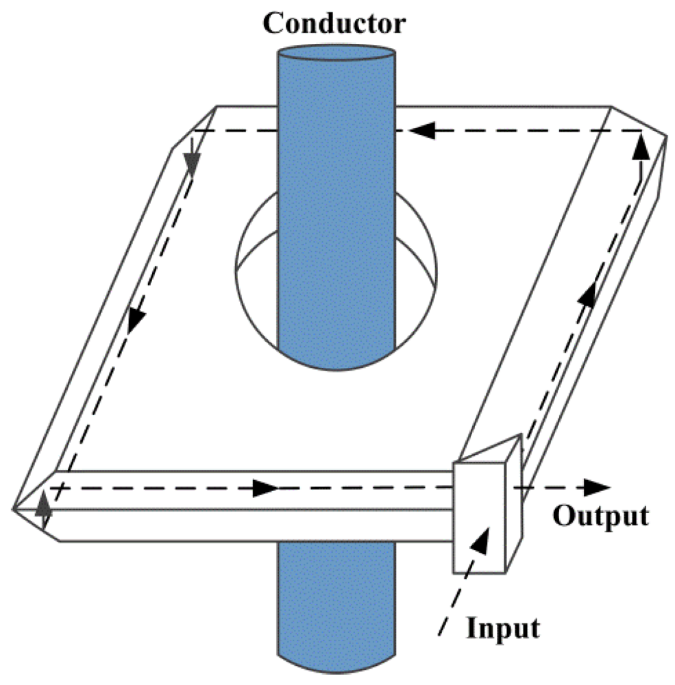
- Ning, Y.N.; Chu, B.; Jackson, D.A. Miniature Faraday current sensor based on multiple critical angle reflections in a bulk-optic ring. Opt. Lett. 1991, 16, 1996–1998. [Google Scholar] [CrossRef]
- Ning, Y.N.; Wang, Z.P.; Palmer, A.W.; Gratan, K. A Faraday current sensor using a novel multi-optical-loop sensing element. Meas. Sci. Technol. 1995, 6, 1339–1342. [Google Scholar] [CrossRef]
- Benshun, Y.; Andrew, C.; Madden, I.; MacDonald, J.R.; Andonovic, I. A Novel bulk-glass optical current transducer having an adjustable multiring closed-optical-path. IEEE Trans. Instru. Meas. 1998, 47, 240–243. [Google Scholar] [CrossRef]
- Wang, Z.P.; Wang, H.; Jiang, H.; Liu, X. A magnetic field sensor based on orthoconjugate reflection used for current sensing. Opt. Laser Technol. 2007, 39, 1231–1233. [Google Scholar] [CrossRef]
- Wang, Z.P.; Qing, B.; Q. Yi, J.Z.; Jin, H. Wavelength dependence of the sensitivity of a bulk-glass optical current transformer. Opt. Laser Technol. 2006, 38, 87–93. [Google Scholar] [CrossRef]
- Wang, Z.P.; Xiaozhong, W.; Liu, X.; Chunmei, O.; Tan, Q. Effect of the spectral width of optical sources upon the output of an optical current sensor. Meas. Sci. Technol. 2005, 16, 1588–1592. [Google Scholar] [CrossRef]
- Madden, W.I.; Michie, W.C.; Cruden, A.; Niewczas, P.; McDonald, J.R. Temperature compensation for optical current sensors. Opt. Eng. 1999, 38, 1699–1707. [Google Scholar] [CrossRef]
- Deng, X.Y.; Li, Z.; Qixian, P.; Liu, J.; Tian, J. Research on the magneto-optic current sensor for highcurrent pulses. Rev. Sci. Instru. 2008, 79, 1–4. [Google Scholar]
- Cruden, A.; Michie, C.; Madden, I.; Niewczas, P.; McDonald, J.R.; Andonovic, I. Optical current measurement system for high-voltage applications. Measurement 1998, 24, 97–102. [Google Scholar] [CrossRef]
- PowerSense A/S—DISCOS System. Available online: http://www.powersense.dk/ (accessed on 15 December 2011).
- Yariv, A.; Winsor, H.V. Proposal for detection of magnetic-fields through magnetostrictive perturbation of optical fibers. Opt. Lett. 1980, 5, 87–89. [Google Scholar] [CrossRef]
- Dandridge, A.; Tveten, A.B.; Sigel, G.H.; West, E.J.; Giallorenzi, T.G. Optical fiber magnetic-field sensors. Electron. Lett. 1980, 16, 408–409. [Google Scholar] [CrossRef]
- Koo, K.P.; Sigel, G.H. Characteristics of fiberoptic magnetic-field sensors employing metallic glasses. Opt. Lett. 1982, 7, 334–336. [Google Scholar] [CrossRef]
- Kersey, A.D.; Jackson, D.A.; Corke, M. Single-mode fibre-optic magnetometer with DC bias field stabilization. J. Lightwave Technol. 1985, 3, 836–840. [Google Scholar] [CrossRef]
- Bucholtz, F.; Koo, K.P.; Dandridge, A. Effect of external perturbations on fiber-optic magnetic sensors. J. Lightwave Technol. 1988, 6, 507–512. [Google Scholar] [CrossRef]
- Jarzynski, J.; Cole, J.H.; Bucaro, J.A.; Davis, C.M. Magnetic-field sensitivity of an optical fiber with magnetostrictive jacket. Appl. Opt. 1980, 19, 3746–3748. [Google Scholar] [CrossRef]
- Sedlar, M.; Paulicka, I.; Sayer, M. Optical fiber magnetic field sensors with ceramic magnetostrictive jackets. Appl. Opt. 1996, 35, 5340–5344. [Google Scholar] [CrossRef]
- Mora, J.; Diez, A.; Cruz, J.L.; Andres, M.V. A magnetostrictive sensor interrogated by fiber gratings for DC-Current and temperature discrimination. IEEE Photon. Technol. Lett. 2000, 12, 1680–1682. [Google Scholar] [CrossRef]
- Quintero, S.M.M.; Martelli, C.; Braga, A.M.B.; Valente, L.C.G.; Kato, C.C. Magnetic field measurements based on terfenol coated photonic crystal fibers. Sensors 2011, 11, 11103–11111. [Google Scholar] [CrossRef]
- Heaton, H.I. Thermal straining in a magnetostrictive optical fiber interferometer. Appl. Opt. 1980, 19, 3719–3720. [Google Scholar] [CrossRef]
- Rashleigh, S.C. Magnetic-field sensing with a single-mode fiber. Opt. Lett. 1981, 6, 19–21. [Google Scholar] [CrossRef]
- Cole, J.H.; Lagakos, N.; Jarzynski, J.; Bucaro, J.A. magneto-optic coupling coefficient for fiber interferometric sensors. Opt. Lett. 1981, 6, 216–218. [Google Scholar] [CrossRef]
- Hartman, N.; Vahey, D.; Kidd, R.; Browning, M. Fabrication and testing of a nickel-coated single-mode fiber magnetometer. Electron. Lett. 1982, 18, 224–226. [Google Scholar] [CrossRef]
- Willson, J.P.; Jones, R.E. Magnetostrictive fiber-optic sensor system for detecting DC magnetic-fields. Opt. Lett. 1983, 8, 333–335. [Google Scholar] [CrossRef]
- Kersey, A.D.; Corke, M.; Jackson, D.A.; Jones, J.D.C. Detection of DC and low-frequency AC magnetic-fields using an all single-mode fiber magnetometer. Electron. Lett. 1983, 19, 469–471. [Google Scholar] [CrossRef]
- Koo, K.; Dandridge, A.; Tveten, A.; Sigel, G., Jr. A fiber-optic DC magnetometer. J. Lightwave Technol. 1983, 1, 524–525. [Google Scholar] [CrossRef]
- Kersey, A.D.; Corke, M.; Jackson, D.A. phase-shift nulling dc-field fibre-optic magnetometer. Electron. Lett. 1984, 20, 573–574. [Google Scholar] [CrossRef]
- Bucholtz, F.; Dagenais, D.M.; Koo, K.P. Mixing and detection of Rf signals in fibre-optic magnetostrictive sensor. Electron. Lett. 1989, 25, 1285–1286. [Google Scholar] [CrossRef]
- Bucholtz, F.; Dagenais, D.M.; Koo, K.P. High-frequency fiberoptic magnetometer with 70 Ft/square-root (hz) resolution. Electron. Lett. 1989, 25, 1719–1721. [Google Scholar] [CrossRef]
- Oh, K.D.; Ranade, J.; Arya, V.; Wang, A.; Claus, R.O. Optical fiber Fabry-Perot interferometric sensor for magnetic field measurement. IEEE Photon. Technol. Lett. 1997, 9, 797–799. [Google Scholar] [CrossRef]
- Perez-Millan, P.; Martinez-Leon, L.; Diez, A.; Cruz, J.L.; Andres, M.V. A fiber-optic current sensor with frequency-codified output for high-voltage systems. IEEE Photon. Technol. Lett. 2002, 14, 1339–1341. [Google Scholar] [CrossRef]
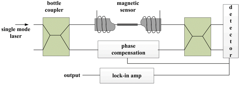
- Djinovic, Z.; Tomic, M.; Gamauf, C. Fiber-optic interferometric sensor of magnetic field for structural health monitoring. In Eurosensors XXIV Conference, Linz, Austria, 5–8 September 2010; 5, pp. 1103–1106.
- Yi, B.; Chu, B.C.B.; Chiang, K.S. Temperature compensation for a fiber-Bragg-grating-based magnetostrictive sensor. Microwave Opt. Technol. Lett. 2003, 36, 211–213. [Google Scholar] [CrossRef]
- Satpathi, D.; Moore, J.A.; Ennis, M.G. Design of a Terfenol-D based fiber-optic current transducer. IEEE Sens. J. 2005, 5, 1057–1065. [Google Scholar] [CrossRef]
- Li, M.F.; Zhou, J.F.; Xiang, Z.Q.; Lv, F.Z. Giant magnetostrictive magnetic fields sensor based on dual fiber Bragg gratings. In 2005 IEEE Networking, Sensing and Control Proceedings, Arizona, AZ, USA, 19–22 March2005; pp. 490–495.
- Mora, J.; Martinez-Leon, L.; Diez, A.; Cruz, J.L.; Andres, M.V. Simultaneous temperature and ac-current measurements for high voltagelines using fiber Bragg gratings. Sens. Actuat. A Phys. 2006, 125, 313–316. [Google Scholar] [CrossRef]
- Reilly, D.; Willshire, A.J.; Fusiek, G.; Niewczas, P.; McDonald, J.R. A fiber-Bragg-grating-based sensor for simultaneous AC current and temperature measurement. IEEE Sens. J. 2006, 6, 1539–1542. [Google Scholar] [CrossRef]
- Davino, D.; Visone, C.; Ambrosino, C.; Campopiano, S.; Cusano, A.; Cutolo, A. Compensation of hysteresis in magnetic field sensors employing fiber Bragg grating and magneto-elastic materials. Sens. Actuat. A Phys. 2008, 147, 127–136. [Google Scholar] [CrossRef]
- Yang, M.H.; Dai, J.X.; Zhou, C.M.; Jiang, D.S. Optical fiber magnetic field sensors with TbDyFe magnetostrictive thin films as sensing materials. Opt. Express 2009, 17, 20777–20782. [Google Scholar]
- Pacheco, C.J.; Bruno, A.C. The effect of shape anisotropy in giant magnetostrictive fiber Bragg grating sensors. Meas. Sci. Technol. 2010, 21, 065205–065209. [Google Scholar] [CrossRef]
- Quintero, S.M.M.; Braga, A.M.B.; Weber, H.I.; Bruno, A.C.; Araujo, J.F.D.F. A Magnetostrictive composite-fiber Bragg grating sensor. Sensors 2010, 10, 8119–8128. [Google Scholar]
- Smith, G.N.; Allsop, T.; Kalli, K.; Koutsides, C.; Neal, R.; Sugden, K.; Culverhouse, P.; Bennion, I. Characterisation and performance of a Terfenol-D coated femtosecond laser inscribed optical fibre Bragg sensor with a laser ablated microslot for the detection of static magnetic fields. Opt. Express 2011, 19, 363–370. [Google Scholar]
- Yang, S.Y.; Chiu, Y.P.; Jeang, B.Y.; Horng, H.E.; Hong, C.Y.; Yang, H.C. Origin of field-dependent optical transmission of magnetic fluid films. Appl. Phys. Lett. 2001, 79, 2372–2374. [Google Scholar]
- Yang, S.Y.; Chen, Y.F.; Horng, H.E.; Hong, H.E.; Hong, C.Y.; Tse, W.S.; Yang, H.C. Magnetically-modulated refractive index of magnetic fluid films. Appl. Phys. Lett. 2002, 81, 4931–4933. [Google Scholar]
- Yang, S.Y.; Chieh, J.J.; Horng, H.E.; Hong, C.Y.; Yang, H.C. Origin and applications of magnetically tunable refractive index of magnetic fluid films. Appl. Phys. Lett. 2004, 84, 5204–5206. [Google Scholar]
- Liu, T.; Chen, X.; Di, Z.; Zhang, J.; Li, X.; Chen, J. Tunable magneto-optical wavelength filter of long-period fiber grating with magnetic fluids. Appl. Phys. Lett. 2007, 91, 121116:1–121116:3. [Google Scholar]
- Hu, T.; Zhao, Y.; Li, X.; Chen, J.J.; Lu, Z.W. Novel optical fiber current sensor based on magnetic fluid. Chin. Opt. Lett. 2010, 8, 392–394. [Google Scholar]
- Dai, J.X.; Yang, M.H.; Li, X.B.; Liu, H.L.; Tong, X.L. Magnetic field sensor based on magnetic fluid clad etched fiber Bragg grating. Opt. Fiber Technol. 2011, 17, 210–213. [Google Scholar] [CrossRef]
- Thakur, H.V.; Nalawade, S.M.; Gupta, S.; Kitture, R.; Kale, S.N. Photonic crystal fiber injected with Fe3O4 nanofluid for magnetic field detection. Appl. Phys. Lett. 2011, 99, 161101:1–161101:3. [Google Scholar]
- Zu, P.; Chan, C.C.; Siang, L.W.; Jin, Y.X.; Zhang, Y.F.; Fen, L.H.; Chen, L.H.; Dong, X.Y. Magneto-optic fiber Sagnac modulator based on magnetic fluids. Opt. Lett. 2011, 36, 1425–1427. [Google Scholar]
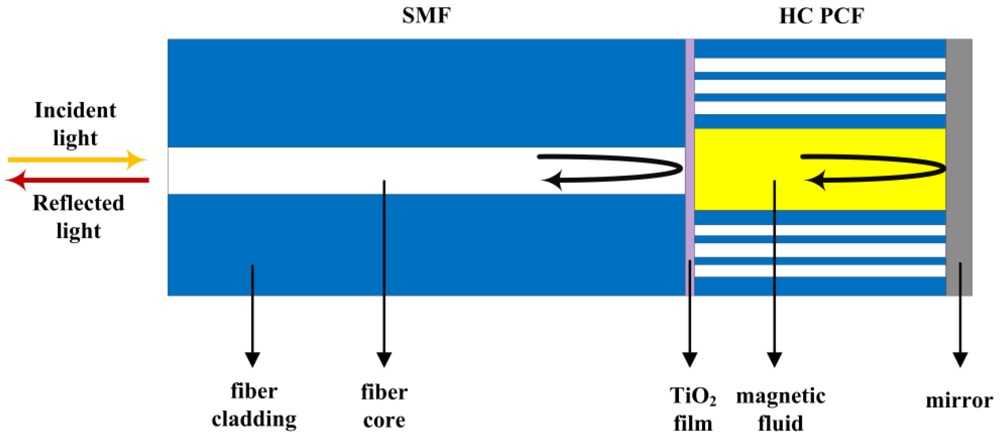
- Zhao, Y.; Lv, R.Q.; Ying, Y.; Wang, Q. Hollow-core photonic crystal fiber Fabry-Perot sensor for magnetic field measurement based on magnetic fluid. Opt. Laser Technol. 2012, 44, 899–902. [Google Scholar] [CrossRef]
- Zu, P.; Chan, C.C.; Lew, W.S.; Jin, Y.X.; Zhang, Y.F.; Liew, H.F.; Chen, L.H.; Wong, W.C.; Dong, X.Y. Magneto-optical fiber sensor based on magnetic fluid. Opt. Lett. 2012, 37, 398–400. [Google Scholar]
- Ning, Y.N.; Chu, B.C.B.; Jackson, D.A. Interrogation of a conventional current transformer by a fiberoptic interferometer. Opt. Lett. 1991, 16, 1448–1450. [Google Scholar] [CrossRef]
- Ning, Y.N.; Liu, T.Y.; Jackson, D.A. Two low-cost robust electrooptic hybrid current sensors capable of operation at extremely high-potential. Rev. Sci. Instru. 1992, 63, 5771–5773. [Google Scholar] [CrossRef]
- Tonnesen, O.; Beatty, N.; Skilbreid, O. Electrooptic methods for measurement of small DC currents at high-voltage level. IEEE Trans. Power Delivery 1989, 4, 1568–1572. [Google Scholar] [CrossRef]
- Pilling, N.A.; Holmes, R.; Jones, G.R. Optical-fiber line current measurement system. In Sixth International Conference on Dielectric Materials, Measurements and Applications, Manchester, England, 7 September 1992; 363, pp. 278–281.
© 2012 by the authors; licensee MDPI, Basel, Switzerland. This article is an open-access article distributed under the terms and conditions of the Creative Commons Attribution license (http://creativecommons.org/licenses/by/3.0/).
Share and Cite
Silva, R.M.; Martins, H.; Nascimento, I.; Baptista, J.M.; Ribeiro, A.L.; Santos, J.L.; Jorge, P.; Frazão, O. Optical Current Sensors for High Power Systems: A Review. Appl. Sci. 2012, 2, 602-628. https://doi.org/10.3390/app2030602
Silva RM, Martins H, Nascimento I, Baptista JM, Ribeiro AL, Santos JL, Jorge P, Frazão O. Optical Current Sensors for High Power Systems: A Review. Applied Sciences. 2012; 2(3):602-628. https://doi.org/10.3390/app2030602
Chicago/Turabian StyleSilva, Ricardo M., Hugo Martins, Ivo Nascimento, José M. Baptista, António Lobo Ribeiro, José L. Santos, Pedro Jorge, and Orlando Frazão. 2012. "Optical Current Sensors for High Power Systems: A Review" Applied Sciences 2, no. 3: 602-628. https://doi.org/10.3390/app2030602