Article

Electrohydrodynamic Nanofluid Hydrothermal Treatment in an Enclosure with Sinusoidal Upper Wall

1
Department of Mechanical Engineering, Babol University of Technology, Babol 47144, Iran
2
Department of Mathematics & Statistics, FBAS, IIUI, H-10 Sector, Islamabad 44000, Pakistan
3
Department of Mechanical Engineering, University of California Riverside, Riverside, CA 92521, USA
*
Author to whom correspondence should be addressed.
Appl. Sci. 2015, 5(3), 294-306; https://doi.org/10.3390/app5030294
Submission received: 8 July 2015 / Revised: 27 July 2015 / Accepted: 28 July 2015 / Published: 7 August 2015
(This article belongs to the Section Nanotechnology and Applied Nanosciences)

Abstract

:
The influence of non-uniform electric filed on Fe3O4-Ethylene glycol nanofluid hydrothermal treatment in an enclosure with sinusoidal upper and moving lower walls is investigated in this study. Control Volume based Finite Element Method (CVFEM) is utilized to simulate in the presented model. Numerical investigation are conducted for the sundry parameters such as Reynolds number; nanoparticle volume fraction and supplied. Results show that supplied voltage can change the flow shape. Coulomb force causes isotherms denser near the moving wall. Heat transfer rises with augment of supplied voltage and Reynolds number. Effect of electric filed on heat transfer is more pronounced at low Reynolds number. Finally, a comparison with the existing literature is also made.

1. Introduction

Unlike free or forced convection, Electrohydrodynamic convection has not yet been well described. In the previous works, an experimental method is applied to investigate electric field effect. Also, there are few papers in which authors considered the combined effect of nanofluid and electric field for enhancement in heat transfer. Furthermore, there is no paper in which Control Volume based Finite Element Method applied for Electrohydrodynamic nanofluid flow and heat transfer. Replacing a smooth wall with a wavy-wall is another commonly used passive method for enhancing the heat transfer in applications where space restrictions are stringent. A wavy-walled geometry is easy to generate and can provide significant heat transfer augmentation if operated in an appropriate Reynolds number range. The corrugations in the wavy-wall act as turbulence generators with the sole purpose of improving the heat transfer. The wavy surface structure adds a degree of complexity to the flow by inducing streamline curvature, flow separation and flow reattachment, thus leading to complex flow situations. The wavy wall provides considerable enhancement of heat transfer with a low pressure drop penalties, thus posing a potential to be considered in several applications such as turbine blade cooling. The target of the current article is to investigate Electrohydrodynamic nanofluid flow and force convective heat transfer via CVFEM.
One of the important active methods for improving rate of heat transfer is utilizing an electric field. The influence of electric field on buoyancy-induced flow was studied by Shu and Lai [1]. In their study, electrodynamics equations are separated from fluid dynamics equations. The influence of electrode arrangements on rate of heat transfer was studied by Kasayapanand et al. [2]. The influence of electric field on fluid flow over a plate has been investigated by Velkoff and Godfrey [3]. Lee et al. [4] changed the fluid flow style in a channel by adding electric field. Hsiao [5] studied the heat and mass transfer of a steady laminar boundary-layer flow of an electrically magnetic conducting fluid of second-grade subject to suction and to a transverse uniform magnetic and electric field past a semi-infinite stretching sheet.
In order to improve the thermo physical characteristics of base fluid, nano scale metal can be added in the base fluid. In which way, thermal conductivity of fluid rises and in turn heat transfer can be enhanced. Khanafer et al. [6] used Finite Volume Method to simulate nanofluid hydrothermal improvement. They indicated that adding nanoparticles leads to rise in Nusselt number. Rahman et al. [7] investigated nanofluid hydrothermal treatment in a tilted enclosure with moving wall. They proved that temperature enhances with rise of nanofluid volume fraction. Combined nanofluid free and force convection heat transfer in an enclosure with moving wall has been studied by Rahman et al. [8]. They verified that rate of improvement is more pronounced at higher tilt angle. Sheikholeslami and Ellahi [9] studied three dimensional mesoscopic simulation of magnetic field effect on natural convection of nanofluid. They found that thermal boundary layer thickness increases with increase of Lorentz forces. Energy conversion for conjugate conduction, convection and radiation analysis has been performed by Hsiao [10] for free convection heat transfer. Their results were shown that the free convection effect will be produced a larger heat transfer effect better than the forced convection. Sheikholeslami et al. [11] studied the effect of thermal radiation on magnetohydrodynamics nanofluid flow and heat transfer. They found that found that concentration boundary layer thickness decreases with the increase of radiation parameter. Boutina and Bessaïh [12] presented the laminar mixed convection air-cooling of two identical heat sources, simulating electronic components, mounted in an inclined channel. Their results indicated that the Reynolds number, the inclination angle of the channel, the dimensions of the heat sources, and the spacing between them have considerable effects on the improvement of the heat transfer inside the channel. Asymmetric laminar flow and heat transfer of nanofluid between contracting rotating disks was investigated by Hatami et al. [13]. Their results indicated that temperature profile becomes more flat near the middle of two disks with the increase of injection but the opposite trend is observed with increase of expansion ratio. Some relevant studies on the topic can be seen from the list of references [14,15,16,17,18,19,20,21,22].
Due to the importance of heat exchangers in many engineering applications, the subject of potential heat transfer enhancement in these devices has received substantial attention in research and practice. In the field of heat exchanger performance, it is known that utilization of wavy walls (or corrugations) can potentially lead to better heat transfer performance due to enhanced mixing of the fluid by the wavy surfaces [23,24].
Control Volume based Finite Element Method (CVFEM) is a new numerical method in which benefits of both finite element and finite volume methods are combined. This method can be used for simulation of complex geometries with multi-physics ([25]). Sheikholeslami et al. [26] utilized an active method (magnetic field) to find the impact of Hartmann number on natural convection of nanofluid. They proved that the effect of Lorentz forces is greater for high Relight number. Ferrofluid heat transfer treatment in the presence of variable magnetic field has been studied by Sheikholeslami and Rashidi [27]. They found that Nusselt number increases by considering magnetic field dependent viscosity.

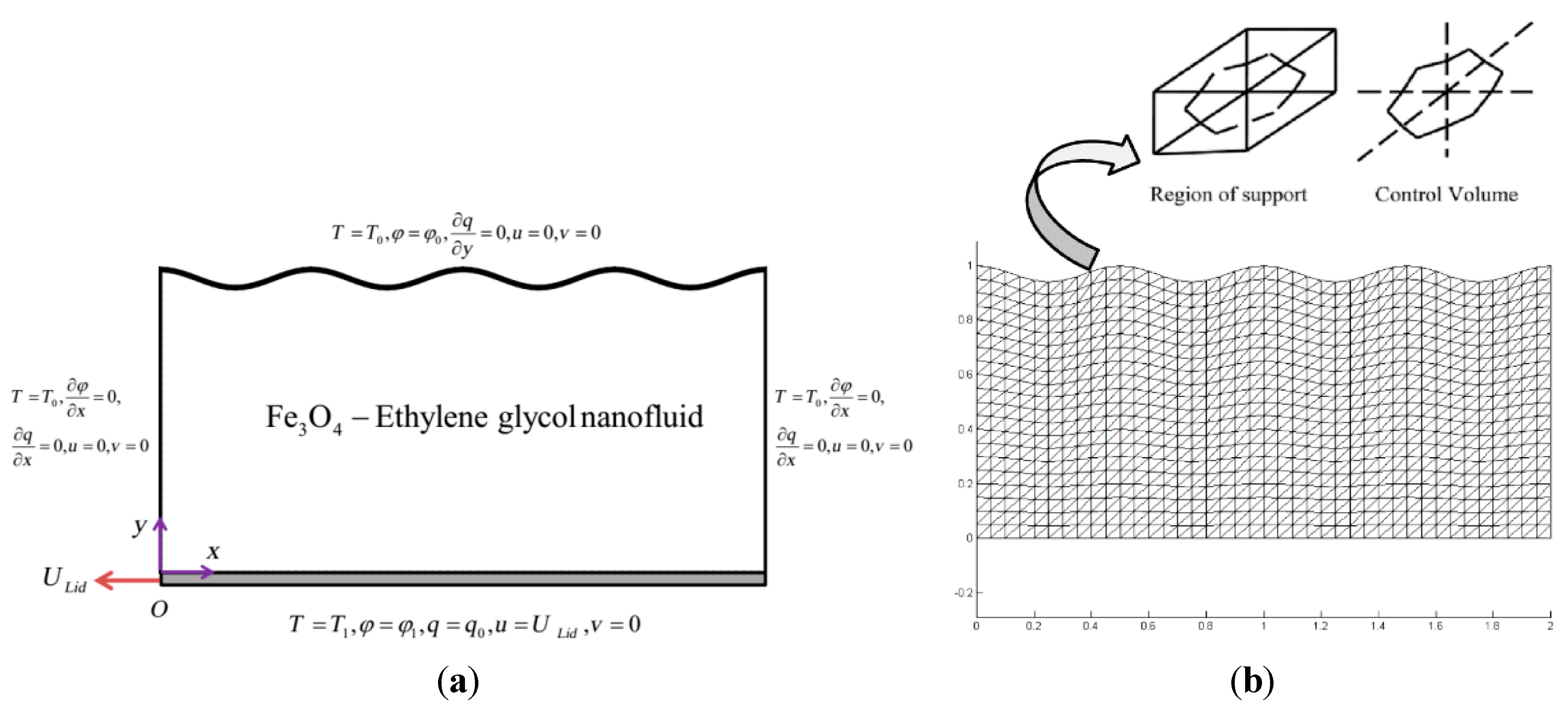
2. Problem Definition

Figure 1 illustrates the physical geometry along with the important parameters and mesh of the enclosure.
Figure 1. (a) Geometry of the problem and boundary conditions; (b) the mesh of enclosure considered in this work.
Applsci 05 00294 g001
The lower wall has the velocity of U L i d and others are stationary. The lower wall has constant temperature T 1 and the temperature of other walls is T 0 Also the retain boundary conditions are depicted in Figure 1a.
The formula of the upper sinusoidal wall is:
Y = 1 { 0.03 ( 1 + sin ( 2 π x π / 2 ) ) }
Figure 2 depicts the distribution of electric density for different Reynolds number and supplied voltage.
Figure 2. Electric density distribution injected by the bottom electrode.
Applsci 05 00294 g002

3. Governing Equations

3.1. Mathematical Model

In order to simulate nanofluid hydrothermal treatment in existence of electric field, we should combined equations of electric fields with those of hydrothermal. The formulas of electric field are:
. ( E ε ) = q
( φ ) = E
. J + q t = 0
There exist two model for charge distribution: (1) conductivity model [28] and (2) mobility model [29]. In first model, electro-convection rely on temperature gradient. But in second model, electro-convection is independent of temperature gradient in the liquid. In the case of free charge origination, second model is more acceptable according to experimental results. Electric current density can be defined as [30]:
J = σ E D q + q V
Where σ E is ionic mobility, D q is diffusion [31], q V is convection.
According to Equations (4) and (5), the equation for electric charge density can be obtained as follow:
q ¯ t ¯ + v ¯ q ¯ y ¯ + u ¯ q ¯ x ¯ + 1 Re Pr E [ q ¯ ( E y ¯ y ¯ + E x ¯ x ¯ ) + E y ¯ q ¯ y ¯ + E x ¯ q ¯ x ¯ ] = ρ n f / ρ f μ n f / μ f 1 Re D e ( 2 q ¯ y ¯ 2 + 2 q ¯ x ¯ 2 )
According to [30] the diffusion term can be taken negligible. Also D q in Equation (5) can be taken negligible and σ = b q [31]. So Equation (5) can be considered as:
J = q V + q b E
In presence of electric field Coulomb forces should be added to momentum equation and Joule heating effect should be added in energy equation. So we have:
{ . V = 0 ρ n f ( V t + ( V . ) V ) = p + μ n f 2 V + q E ( ρ C p ) n f ( T t + ( V . ) T ) = k n f 2 T + J . E . J + q t = 0 . ε E = q E = φ
ρ n f , ( ρ C p ) n f , α n f , μ n f and k n f are defined as [6]:
ρ n f = ρ s ϕ + ρ f ( 1 ϕ )
( ρ C p ) n f = ( ρ C p ) s ϕ + ( ρ C p ) f ( 1 ϕ )
α n f = k n f / ( ρ C p ) n f
μ n f = μ f ( 1 ϕ ) 2.5
k n f = k f 2 ϕ ( k f k s ) + 2 k f + k s + ϕ ( k f k s ) s + 2 k f + k
The thermo physical properties of the working fluid are given in Table 1. Non-dimensional parameters are introduced as follows:
t ¯ = t U L i d L , p ¯ = P ρ U L i d 2 , y ¯ = y L , x ¯ = x L , v ¯ = v U L i d , u ¯ = u U L i d , θ = T T 0 T , T = T 1 T 0 , φ ¯ = φ φ 0 φ , φ = φ 1 φ 0 , q ¯ = q q 0 , E ¯ = E E 0
In order to reach clear formulation, over bar will be deleted in next equations. So, the governing equations can be considered as follows:
{ . ( V ) = 0 ( V t + ( V . ) V ) = p + ρ n f / ρ f μ n f / μ f 1 Re 2 V + S E ρ n f / ρ f q E ( θ t + ( V . ) θ ) = k n f / k f ( ρ C p ) n f / ( ρ C p ) f 1 RePr 2 θ + S E E c ( ρ C p ) n f / ( ρ C p ) f ( J . E ) . J + q t = 0 . ε E = q E = φ
The formulas of vorticity and stream function are:
ω = v x u y , v = ψ x , u = ψ y , Ω = ω L U L i d , Ψ = ψ L U L i d
Continuity equation has been satisfied by the stream function. By eliminating pressure between x-momentum and y-momentum, the vorticity equation can be obtained.
N u l o c and N u a v e along the lid wall can be obtained as:
N u l o c = ( k n f k f ) Θ Y
N u a v e = 1 L 0 L N u l o c d X

3.2. Numerical Method

In order to simulate this problem CVFEM is applied. We used triangular element with linear interpolation through the elements. Shape of control volume is depicted in Figure 1b. We developed FORTRAN code to solve governing equations. More information about this method can be found in [26].

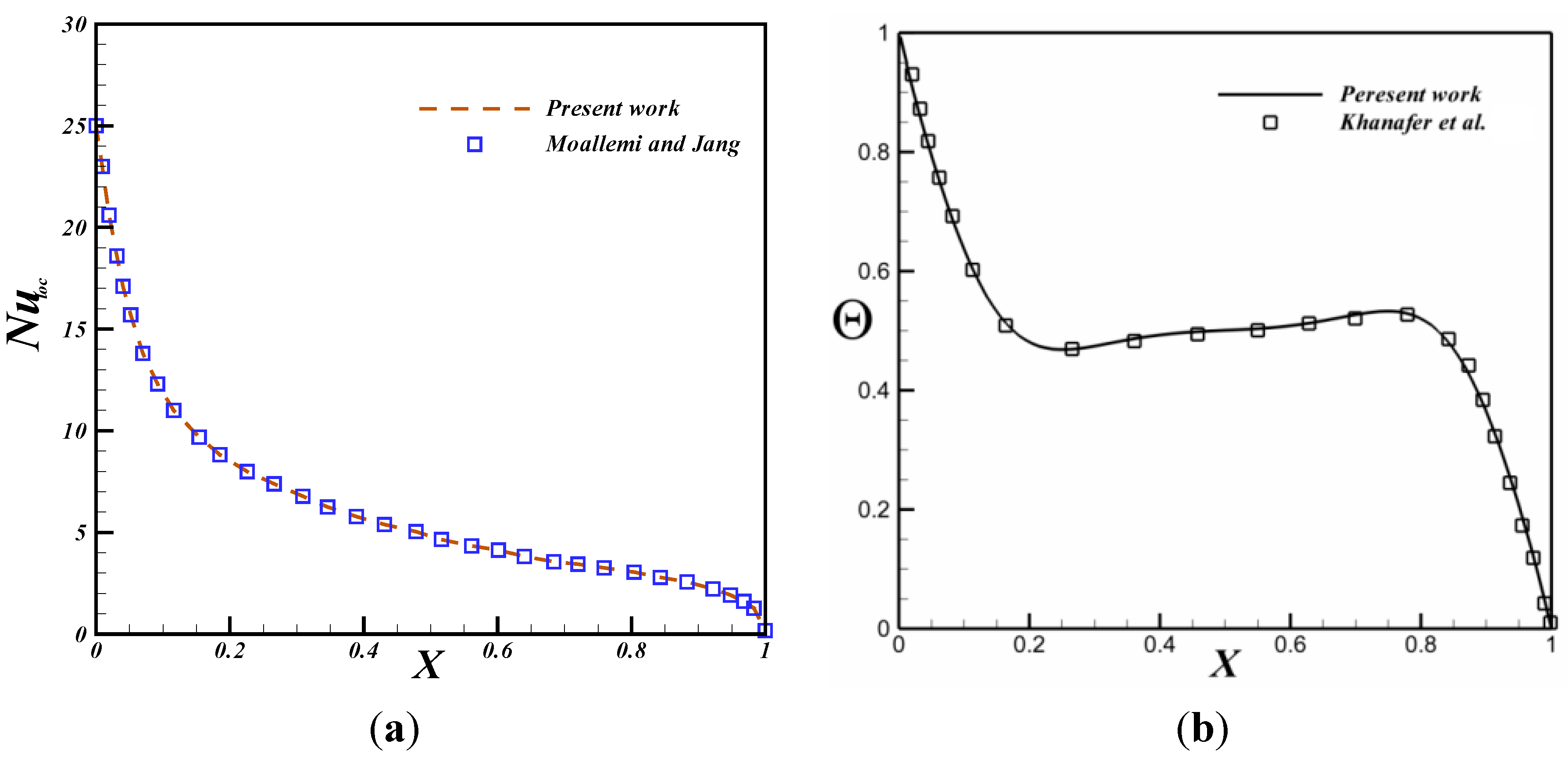
4. Code Verification and Mesh Independency

In order to reach the mesh independent results, various meshes were examined for case of R e = 6000 , ϕ = 0.04 , Δ φ = 10 k V and P r = 149.54 as illustrated in Table 1 According to this table the mesh size of 61 × 121 guarantees a grid-independent solution. Also the convergence limitation is:
max g r i d | Γ n + 1 Γ n | 10 7
Table 1. Comparison of the average Nusselt number N u a v e along bottom wall for different grid resolution at R e = 6000 , Δ φ = 10 k V and P r = 149.54 , ϕ = 0.04 .
Mesh size31 × 6141 × 8151 × 10161 × 12171 × 14181 × 161
N u a v e 6.1802846.1956446.2119046.2319946.2353046.239816
Here Γ is variable ( Ψ , Ω , Θ ). In order to verify the current results, we compared them with those of obtained in [32] (see Figure 2). Furthermore, free convection of nanofluid in a cavity was validated as shown in Figure 3. These figures proved that the current code has good accuracy.
Figure 3. (a) Comparison of the local Nusselt number over the lid wall between the present results and Moallemi and Jang [30] at Re = 500, Ri = 0.4, and Pr = 1; (b) Comparison of average Nusselt number between the present results and numerical results by Khanafer et al. [6] G r = 10 4 , ϕ = 0.1 and P r = 6.8 ( Cu-Water )
Applsci 05 00294 g003

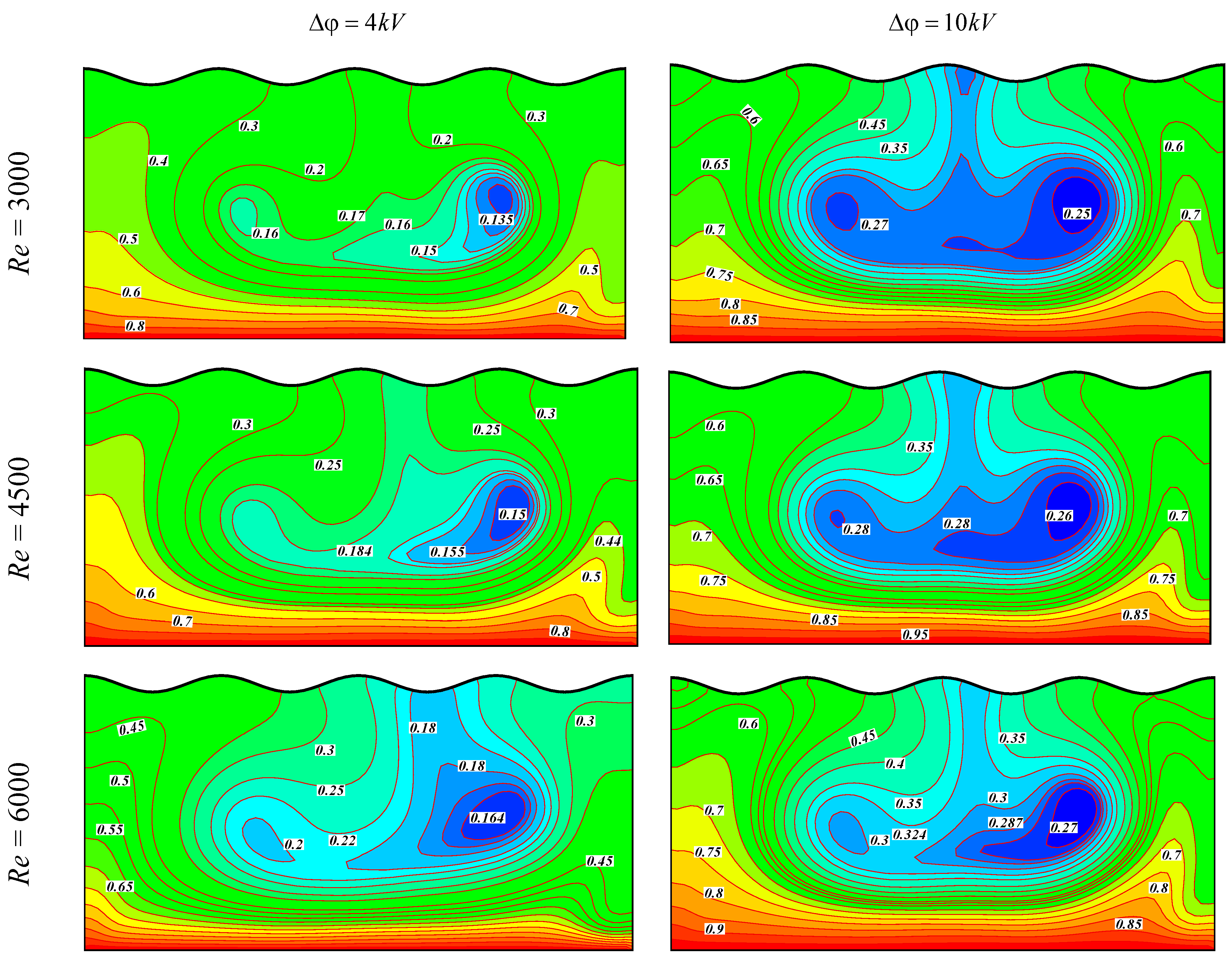
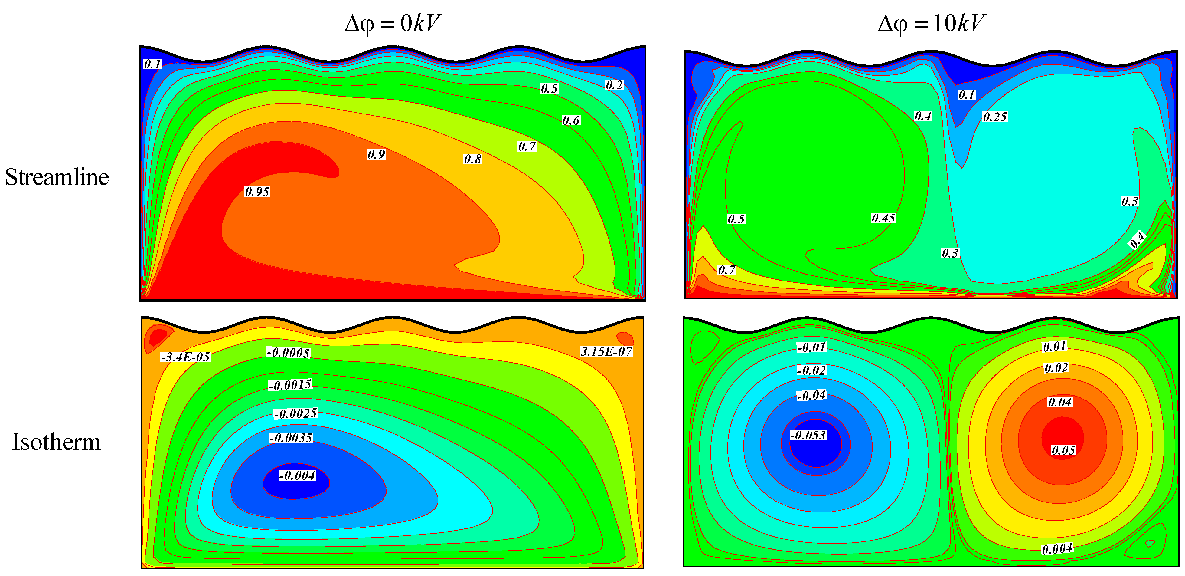
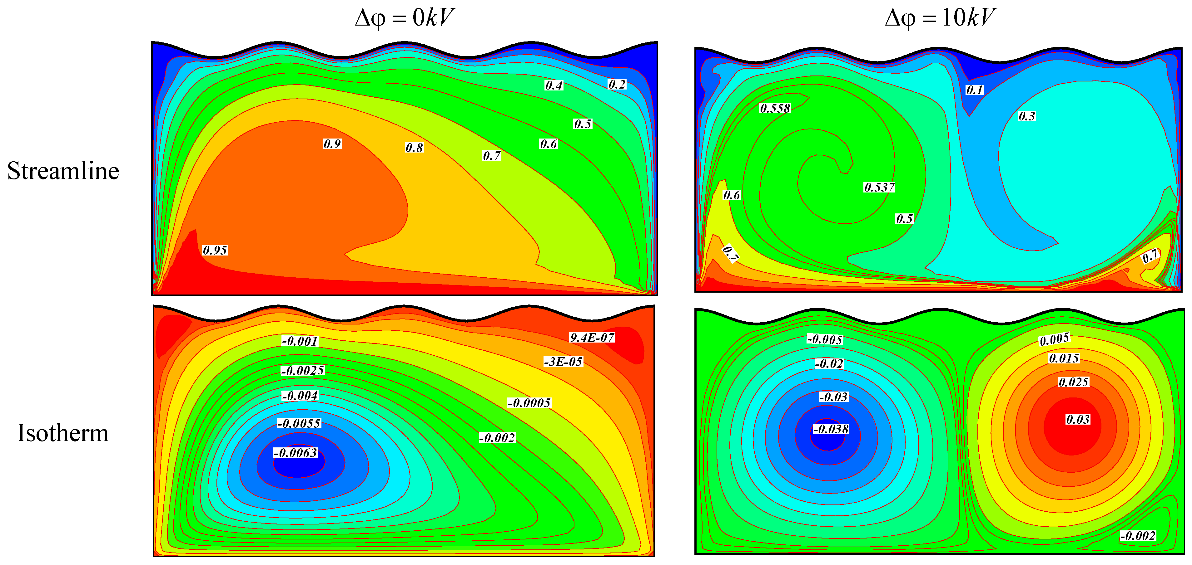
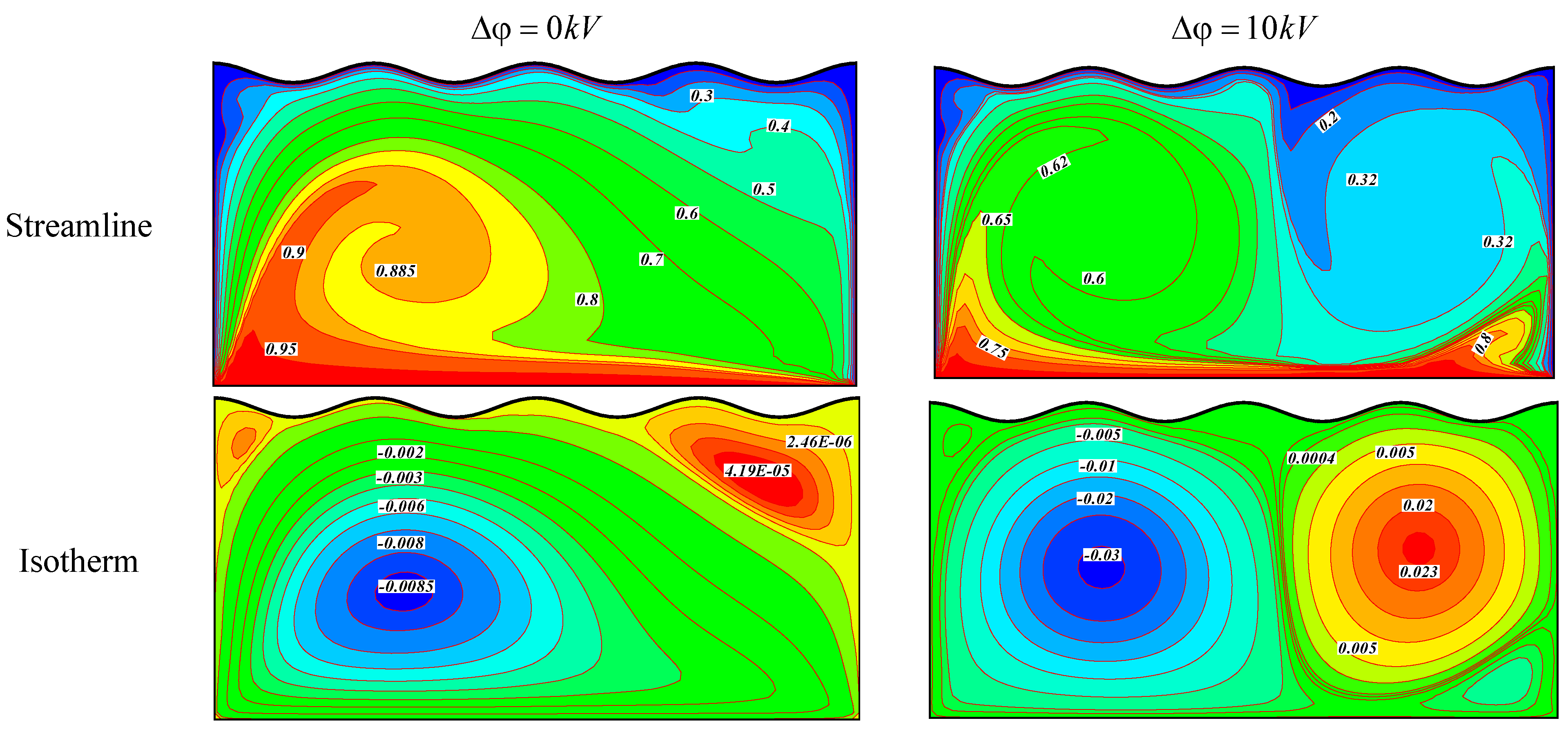
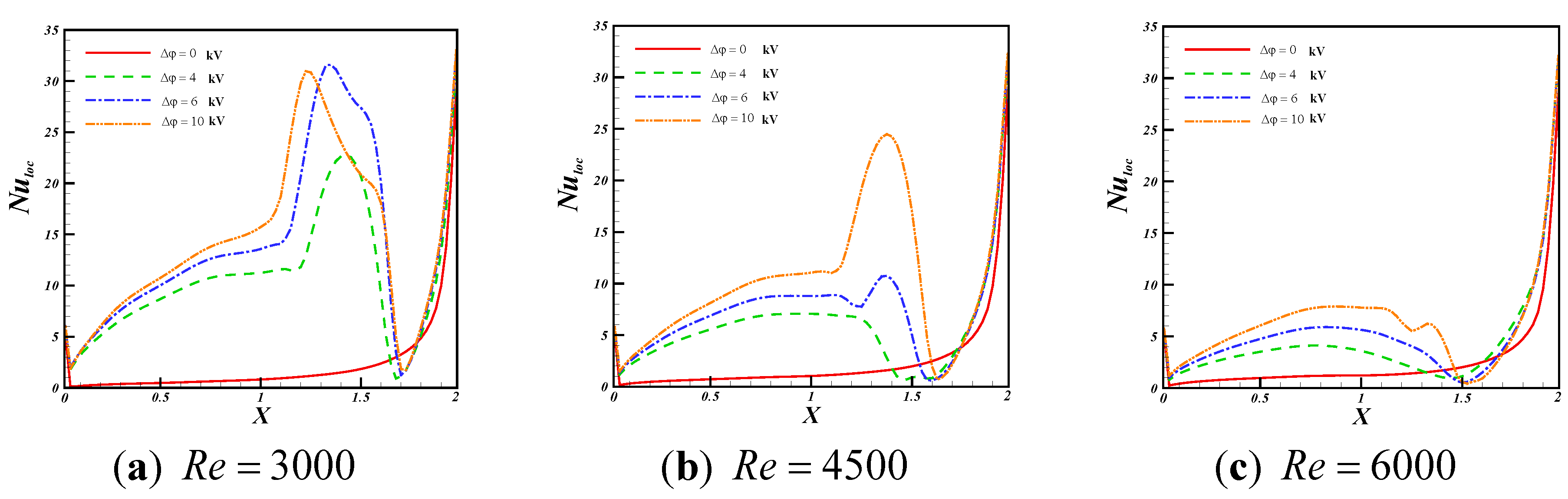
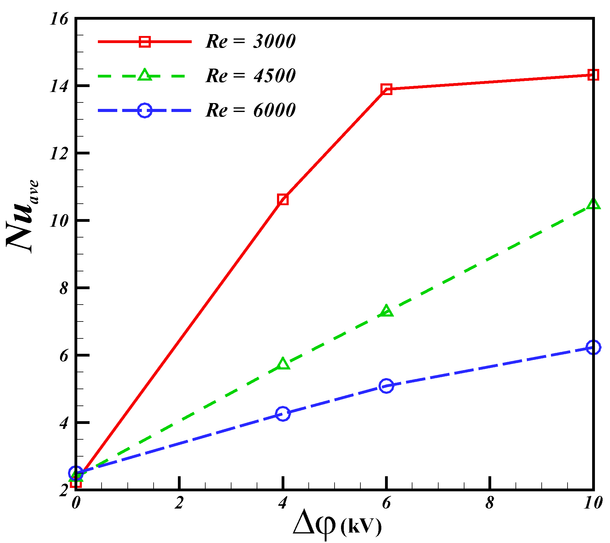
5. Results and Discussion

Electric filed effect on hydrothermal behavior of nanofluid in an enclosure with moving lower and sinusoidal upper walls is presented. Table 2 illustrates the properties of Ethylene glycol and Fe3O4. Calculations are prepared for various values of supplied voltage ( Δ φ = 0 , 4 , 6 and 10 kV), volume fraction of nanoparticles ( ϕ = 0 % and 4%) and Reynolds number numbers ( R e = 3000 , 4500 and 6000). In all calculations, the Prandtl number (Pr) and Eckert number (Ec) are set to 149.54, 0.0 and 10−6.
Table 2. Thermo physical properties of Ethylene glycol and nanoparticles.
Material ρ ( k g / m 3 ) C p ( j / k g k ) k ( W / m . k ) μ ( P a . s )
Ethylene glycol111024000.260.0162
Fe 3 O 4 52006706-
The influence of Reynolds number and supplied voltage on streamlines and isotherm are shown in Figure 4, Figure 5, and Figure 6. At Re = 3000, one main eddy and two very small eddied at upper corners of the enclosure exist in streamline.
Figure 4. Effect of supplied voltage on streamlines and isotherm when R e = 3000 , ϕ = 0.04 .
Applsci 05 00294 g004
As electric filed applied the main eddy turn in to two smaller ones. Also isotherm becomes denser near the hot wall due to existence these eddies. As Reynolds number increases up to 6000, the upper right eddy becomes stronger and isotherms become denser near the bottom wall.
Since convective heat transfer is helped more successfully at a greater flow rate, Nusselt number is improved at great Reynolds numbers. So isotherm becomes more distorted at greater values of Reynolds number. As electric filed increases, the main cell convert to two eddies which are rotates opposite direction.
Figure 5. Effect of supplied voltage on streamlines and isotherm when R e = 4500 , ϕ = 0.04 .
Applsci 05 00294 g005
Figure 6. Effect of supplied voltage on streamlines and isotherm when R e = 6000 , ϕ = 0.04 .
Applsci 05 00294 g006
Figure 7. Effects of Reynolds number and supplied voltage on local Nusselt number for (a) R e = 3000 ; (b) R e = 4500 ; (c) R e = 6000 when ϕ = 0.04 .
Applsci 05 00294 g007
Figure 7 and Figure 8 depict the influences of Δ φ and R e on N u l o c and N u a v e along the lid wall. As Reynolds number increases, Nusselt number increases due to decrease in thermal boundary layer thickness. Increasing supplied voltage make the isotherms more distorted. Local Nusselt number profiles have extremums at higher values of supplied voltage because of existence of thermal plumes.
Nusselt umber is an increasing function of supplied voltage. In absence of electric filed, Nusselt number for Re = 6000 is 1.117 times higher than that of Re = 3000 while in presence of electric filed ( Δ φ = 10 ) , Nusselt number for Re = 6000 is 2.298385 times lower than that of Re = 3000. Also it can be concluded that Nusselt number at Δ φ = 10 for Re = 3000, 4500 and 6000 are times higher than those of obtained at Δ φ = 0 . This observation confirms that impact of electric filed is more marked for lower Reynolds number.
Figure 8. Effects of Reynolds number and supplied voltage on average Nusselt number.
Applsci 05 00294 g008

6. Conclusions

Fe3O4-Ethylene glycol nanofluid hydrothermal treatment in existence of electric field in lid driven cavity with sinusoidal upper wall is presented. The numerical procedure is conduct via Control Volume based Finite Element Method. We reduced continuity and momentum equations to vorticity stream function. We solved the coupled equations together by considering electric filed effect. Numerical outcomes are obtained for various values of supplied voltage, nanofluid volume fraction and Reynolds number. Results show that supplied voltage causes the flow form to change. By applying electric field isotherms becomes denser near the lid wall and this observation is more market for stronger electric filed. In absence of electric filed, Nusselt number for Re = 6000 is 1.117 times higher than that of Re = 3000 while in presence of electric filed ( Δ φ = 10 ) , Nusselt number for Re = 6000 is 2.298385 times lower than that of Re = 3000. Also, it can be concluded that Nusselt number at Δ φ = 10 for Re = 3000, 4500 and 6000 are times higher than those of obtained at Δ φ = 0 . Rate of augmentation in heat transfer rises with increase of strength of electric filed. Also, Nusselt number enhances with rise of Reynolds number. Improvement in Nusselt number due to existence of eclectic field becomes stronger for low Reynolds numbers.

Author Contributions

M. Sheikholeleslami and R. Ellahi wrote this paper together.

Conflicts of Interest

The authors declare no conflicts of interest.

Nomenclature

b ironic mobility [ m 2 / ( s V ) ] T Temperature, [ K ]
C p specific heat capacity [ k J / ( k g K ) ] u , v Cartesian components of velocity, V , [m/s]
D e , D diffusion number ( = μ 0 / ( ρ 0 D 0 ) ) , charge diffusion coefficient, [ m 2 / s ] Greek symbols
E c Eckert number ( = ρ f U L i d 2 / ( ( ρ C p ) f ( T 1 T 0 ) ) ) ε dielectric permittivity
E , E x , E y electric field, [ V / m ] ϕ Volume fraction
F E Coulomb force, [ N ] μ Dynamic viscosity
J electric current density, [ A / m 2 ] ρ Density
L characteristic length, [ m ] σ electric conductivity
N E electric field number ( = q 0 L 2 / ( ε Δ φ ) ) φ electric field potential
p Pressure, [ P a ] Subscripts
P r Prandtl number ( = υ f / α f ) a v e Average
P r E electric Prandtl number ( = μ f / ( ρ f b Δ φ ) ) c Cold
q electric charge density, [ C / m 3 ] s Solid particles
R e Reynolds number ( = ρ f U L i d L / μ f ) f Base fluid
S E Lorentz force number ( = q 0 Δ φ / ( ρ U L i d 2 ) ) h Hot
t Time, [ s ] n f Nanofluid

References

  1. Shu, H.S.; Lai, F.C. Effect of Electrical Field on Buoyancy-Induced Flows in an Enclosure. In Proceedings of the Conference Record—IAS Annual Meeting (IEEE Industry Applications Society), Orlando, FL, USA, 8–12 October 1995; Volume 2, pp. 1465–1471.
  2. Kasayapanand, N.; Tiansuwan, J.; Asvapoositkul, W.; Vorayos, N.; Kiatsiriroat, T. Effect of the electrode arrangements in tube bank on the characteristic of electrohydrodynamic heat transfer enhancement: Low Reynolds number. J. Enhanc. Heat Transf. 2002, 9, 229–242. [Google Scholar] [CrossRef]
  3. Velkoff, H.R.; Godfrey, R. Low velocity heat transfer to a flat plate in the presence of a corona discharge in air. J. Heat Transf. 1979, 101, 157–163. [Google Scholar] [CrossRef]
  4. Lee, S.; Dulikravich, G.S.; Ahuja, V. Computations of Electro-thermo-convective Phenomena in Electro-rheological Fluids; American Society of Mechanical Engineers, Fluids Engineering Division FED: New York, NY, USA, 1993; Volume 164, pp. 29–42. [Google Scholar]
  5. Hsiao, K.-L. Heat and mass mixed convection for MHD visco-elastic fluid past a stretching sheet with ohmic dissipation. Commun. Nonlinear Sci. Numer. Simul. 2010, 15, 1803–1812. [Google Scholar] [CrossRef]
  6. Khanafer, K.; Vafai, K.; Lightstone, M. Buoyancy-driven heat transfer enhancement in a two-dimensional enclosure utilizing nanofluids. Int. J. Heat Mass Transf. 2003, 46, 3639–3653. [Google Scholar] [CrossRef]
  7. Rahman, M.M.; Billah, M.M.; Rahman, A.T.M.M.; Kalam, M.A.; Ahsan, A. Numerical investigation of heat transfer enhancement of nanofluids in an inclined lid-driven triangular enclosure. Int. Commun. Heat Mass Transf. 2011, 38, 1360–1367. [Google Scholar] [CrossRef]
  8. Rahman, M.M.; Oztop, H.F.; Ahsan, A.; Saidur, R.; Al-Salem, K.; Rahim, N.A. Laminar Mixed Convection in Inclined Triangular Enclosures Filled with Water Based Cu Nanofluid. Ind. Eng. Chem. Res. 2012, 51, 4090–4100. [Google Scholar] [CrossRef]
  9. Sheikholeslami, M.; Ellahi, R. Three dimensional mesoscopic simulation of magnetic field effect on natural convection of nanofluid. Int. J. Heat Mass Transf. 2015, 89, 799–808. [Google Scholar] [CrossRef]
  10. Hsiao, K.-L. Energy conversion conjugate conduction-convection and radiation over non-linearly extrusion stretching sheet with physical multimedia effects. Energy 2013, 59, 494–502. [Google Scholar] [CrossRef]
  11. Sheikholeslami, M.; Ganji, D.D.; Javed, M.Y.; Ellahi, R. Effect of thermal radiation on magnetohydrodynamics nanofluid flow and heat transfer by means of two phase model. J. Magn. Magn. Mater. 2015, 374, 36–43. [Google Scholar] [CrossRef]
  12. Boutina, L.; Bessaïh, R. Numerical simulation of mixed convection air-cooling of electronic components mounted in an inclined channel. Appl. Therm. Eng. 2011, 31, 2052–2062. [Google Scholar] [CrossRef]
  13. Hatami, M.; Sheikholeslami, M.; Ganji, D.D. Laminar flow and heat transfer of nanofluid between contracting and rotating disks by least square method. Powder Technol. 2014, 253, 769–779. [Google Scholar] [CrossRef]
  14. Mansur, S.; Ishak, A.; Pop, I. Flow and heat transfer of nanofluid past stretching/shrinking sheet with partial slip boundary conditions. Appl. Math. Mech. 2014, 35, 1401–1410. [Google Scholar] [CrossRef]
  15. Ellahi, R. The effects of MHD and temperature dependent viscosity on the flow of non-Newtonian nanofluid in a pipe: Analytical solutions. Appl. Math. Model. 2013, 37, 1451–1467. [Google Scholar] [CrossRef]
  16. Othman, M.I.A.; Zaki, S.A. The effect of thermal relaxation time on electrohydrodynamic viscoelastic fluid layer heated form below. Can. J. Phys. 2003, 81, 779–787. [Google Scholar] [CrossRef]
  17. Gawande, M.B.; Rathi, A.K.; Branco, P.S.; Varma, R.S. Sustainable Utility of Magnetically Recyclable Nano-Catalysts in Water: Applications in Organic Synthesis. Appl. Sci. 2013, 3, 656–674. [Google Scholar] [CrossRef]
  18. Kefayati, G.H.R. Lattice Boltzmann simulation of natural convection in nanofluid-filled 2D long enclosures at presence of magnetic field. Theor. Comput. Fluid Dyn. 2013, 27, 865–883. [Google Scholar] [CrossRef]
  19. Noreen, S.A.; Nadeem, S. Numerical and analytical simulation of the peristaltic flow of Jeffrey fluid with Reynold’s model of viscosity. Int. J. Numer. Methods Heat Fluid Flow 2012, 22, 458–472. [Google Scholar]
  20. Higashi, T.; Minegishi, H.; Nagaoka, Y.; Fukuda, T.; Echigo, A.; Usami, R.; Maekawa, T.; Hanajiri, T. Effects of Superparamagnetic Nanoparticle Clusters on the Polymerase Chain Reaction. Appl. Sci. 2012, 2, 303–314. [Google Scholar] [CrossRef]
  21. Ganapathirao, M.; Ravindran, R.; Pop, I. Non-uniform slot suction (injection) on an unsteady mixed convection flow over a wedge with chemical reaction and heat generation or absorption. Int. J. Heat Mass Transf. 2013, 67, 1054–1061. [Google Scholar] [CrossRef]
  22. Kefayati, G.H.R. Lattice Boltzmann simulation of MHD natural convection in a nanofluid-filled cavity with sinusoidal temperature distribution. Powder Technol. 2013, 243, 171–183. [Google Scholar] [CrossRef]
  23. Sakanova, A.; Keian, C.C.; Zhao, J. Performance Improvements of Microchannel Heat Sink Using Wavy Channel and Nanofluids. Int. J. Heat Mass Transf. 2015, 89, 59–74. [Google Scholar] [CrossRef]
  24. Wu, J.M.; Zhao, J. A Review of Nanofluids Heat Transfer and Critical heat Flux Enhancement-Research Gap to Engineering Application. Prog. Nucl. Energy 2013, 66, 13–24. [Google Scholar] [CrossRef]
  25. Sheikholeslami, M.; Ganji, D.D. Hydrothermal Analysis in Engineering Using Control Volume Finite Element Method; Academic Press: London, UK, 2015. [Google Scholar]
  26. Sheikholeslami, M.; Bandpy, M.G.; Ellahi, R.; Hassan, M.; Soleimani, S. Effects of MHD on Cu-water nanofluid flow and heat transfer by means of CVFEM. J. Magn. Magn. Mater. 2014, 349, 188–200. [Google Scholar] [CrossRef]
  27. Sheikholeslami, M.; Rashidi, M.M. Ferrofluid heat transfer treatment in the presence of variable magnetic field. Eur. Phys. J. Plus 2015, 130, 115. [Google Scholar] [CrossRef]
  28. Bergles, A.E. Enhancement of Heat Transfer. In Proceedings of the 6th International Journal of Heat and Mass Transfer Conference, Toronto, Canada, 7–11 August 1978; pp. 89–108.
  29. Martin, P.J.; Richardson, A.T. Conductivity Models of Electrothermal Convection in Plane Layer of Dielectric Liquid. J. Heat Transf. 1984, 106, 131–136. [Google Scholar] [CrossRef]
  30. Worraker, W.J.; Richardson, A.T. The Effect of Temperature Variations in Charge Carrier Mobility on a Stationary Electrohydrodynamic Instability. J. Fluid Mech. 1979, 93, 29–45. [Google Scholar] [CrossRef]
  31. Fujino, T.; Yokoyama, Y.; Mori, Y.H. Augmentation of Laminar Forced-Convective Heat Transfer by the Application of a Transverse Electric Field. J. Heat Transf. 1989, 111, 345–351. [Google Scholar] [CrossRef]
  32. Moallemi, M.K.; Jang, K.S. Prandtl number effects on laminar mixed convection heat transfer in a lid-driven cavity. Int. J. Heat Mass Transf. 1992, 35, 1881–1892. [Google Scholar] [CrossRef]

