1. Introduction
Piezoelectric motors have been seen as successors of the electromagnetic ones in areas such as robot joints, high precision machines, micro robots and MEMS. The commercial application in a camera auto-focus system has verified its unique advantage. Furthermore, it has been successfully used in lunar rover Yutu of China, which also shows its advantage for driving aerospace mechanism as the merits of simple structure without coils, quick response at millisecond, high precision and resolution at nanometer, low speed without reducer, self-locking in the power-off state and absence of electromagnetic radiation [
1,
2,
3].
According to the output motion modes, piezoelectric motors can currently be classified into: rotary [
4,
5,
6,
7,
8], linear [
9,
10,
11,
12,
13] and multi-degree-of-freedom motors [
14,
15,
16,
17,
18]. The first type has attracted more attention because of its higher applicability in the above system. Most piezoelectric motors obtain rotary actuating by generating a traveling wave in a metal ring or cylinder [
19,
20]. The ring-shaped traveling wave piezoelectric motor is the most classic and successful one for rotary driving; but it has a complicated operating principle as it needs to generate two bending standing waves with the same frequency, the same amplitude, a temporal shift of 90° and a spatial distance of one quarter wavelength. These requirements make it difficult to be fabricated and controlled. On the other side, the axial and circumferential displacements of the driving teeth are produced by the traveling wave in the stator: one is used to overcome the preload while the other one push the rotor. However, these two displacements are coupled, since they are from one traveling wave, which limits its flexibility on mechanical output performance adjustment.
In this study, we report a novel rotary piezoelectric motor using first bending hybrid transducers. Three transducers are distributed uniformly along the circumferential direction to push a disk-shaped rotor into rotation, and the elliptical movement of the driving tip is produced by the superimposing of two orthogonal first bending modes. The proposed motor has obvious advantages compared with the classic ring-shaped traveling wave piezoelectric motor as the horizontal and vertical vibrations of the driving tip are generated independently by the horizontal and vertical bending modes, which gives the proposed motor good flexibility on mechanical output adjustment. Furthermore, the dimensions of the bending transducer can be adjusted freely to satisfy different requirements for space and weight, and more transducers can be set into the motor to increase its output torque.
2. Structure and Operating Principle
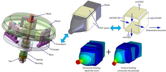
To rotate a disk-shaped rotor, three bending vibration transducers are clamped on the base, and they are set circumferentially with space angle of 120°, as shown in
Figure 1. The proposed transducer has a simple structure as we only need to bond four pieces of PZT plates on a square beam. A cone-shaped horn is machined on one end of the beam to achieve the improvement of vibration amplitude and velocity. The transducers contact with the side surface of the disk-shaped rotor by their horn tips, and a nut-spring system is used to apply the preload.
To drive the rotor circularly, the horn tip should vibrate along two directions: an axial one and a tangential one. The axial motion will overcome the preload while the tangential one can rotate the rotor. We use two first bending modes of the bonded-type transducer to obtain these two displacements respectively, and their vibration shapes are shown in
Figure 2. It can be clearly recognized that the vertical bending will produce axial movement of the end tip, while the tangential motion will be generated by the horizontal bending. To excite these two bending vibrations, the polarizations of the PZT plates and the exiting signals should be arranged as shown in
Figure 1d.
Figure 1.
Structure of the proposed piezoelectric motor: (a) three-dimensional model; (b) section view; (c) the bending transducer; (d) polarizations of the PZT plates.
Figure 1.
Structure of the proposed piezoelectric motor: (a) three-dimensional model; (b) section view; (c) the bending transducer; (d) polarizations of the PZT plates.
Figure 2.
Two first bending vibrations of the transducer: (a) horizontal mode; (b) vertical mode.
Figure 2.
Two first bending vibrations of the transducer: (a) horizontal mode; (b) vertical mode.
The proposed bending transducer has a symmetrical structure, which favors the two first bending modes have the same resonance frequency. Therefore, when applied sine and cosine signals on the PZT plates as shown in
Figure 1d, the vertical and horizontal bending modes will be generated with a temporal shift of 90°, which can form elliptical movement on the horn tip finally. Thus, horizontal and vertical displacements are controlled by the amplitudes of the sine and cosine voltages respectively; this means that we can keep the amplitude of the cosine voltage as a constant and change the amplitude of the sine voltage to obtain different output speeds. Furthermore, the vibration shapes shown in
Figure 2 also indicate that the contact parts between the transducer and the clamper locate near the bending wave loops, where have the minute transverse displacements in resonant vibration mode. Thus, this fixing position will bring in as little effect on its natural vibrations as possible.
3. Working Frequency of the Bending Transducer
Firstly, we used finite element method (Ansys software, ANSYS Inc, Canonsburg, PA, USA) to gain the resonance frequency of the bending transducer by modal analysis.
Figure 3 gives the main dimensions of the FEM model. The material of the beam is aluminum alloy with mass density of 2810 kg/m
3, Young modulus of 7.2 × 10
10 N/m
2 and Poisson ratio of 0.33. The material of the ceramic is PZT-4, whose physical parameters are:
The two first bending modes have the same resonance frequency as the symmetrical structure. During the modal analysis, calculations were accomplished under two different boundary conditions: electrical short-circuit and electrical open. Zero voltages were applied on the PZT plates in the electrical short-circuit calculation, while no voltage was set in the electrical open simulation. These two boundary conditions lead to different resonance frequencies of the bending modes, which are the series resonance frequency fs and the parallel resonance frequency fp, separately.
Figure 3.
Main dimensions of the bending transducer (unit: mm).
Figure 3.
Main dimensions of the bending transducer (unit: mm).
Figure 4.
Parameter sensitivities of the resonance frequencies and electromechanical coupling factor.
Figure 4.
Parameter sensitivities of the resonance frequencies and electromechanical coupling factor.
The length of the horn
L1, the length of the metal beam
L2, and the width of the metal beam
A were changed in the FEM model to obtain their effects on the series and parallel resonance frequencies.
Figure 4 shows the parameter sensitivities of the resonance frequencies and electromechanical coupling factor, in which the electromechanical coupling factor
k was calculated by the following equation:
The calculation results indicate that the resonances frequencies decrease linearly with the lengths of the metal beam and the horn, but increase with the width of the metal beam. The increase of the length of the horn results in the obvious fall of the electromechanical coupling factor, and the width of the metal beam. However, the length of the metal beam shows a minute and nonlinear effect on the electromechanical coupling factor. The distinctive merit of the proposed bending transducer is that its dimensions can be adjusted freely, but always has two identical first bending frequencies. For the size decrease requirement, it is better to decrease the width of the beam in order to maximize efficiency.
4. Movement of the Driving Tip
Then, the vibration amplitude of the driving tip was calculated by transient analysis. A FEM model with
L1 = 11 mm,
L2 = 20 mm and
A = 11 mm was used for the calculation, whose first bending series resonance frequency was 53.762 kHz. We choose these dimensions based on the high electromechanical coupling factor and the size miniaturization. In fact, the proposed transducer can accomplish rotary driving under any dimensions but a symmetrical structure. This is a merit of the proposed design, which allows us to choose its dimensions freely to satisfy the different demands of space, speed and torque. Sine and cosine voltages with a value of 140 V
0-P were applied on the PZT elements, and the transient analysis continued for about 5.58 ms. One particle on the end rim was selected, and its movements was extracted and plotted, see
Figure 5.
The transducer took about 3.5 ms to reach a steady vibration. The calculated result states that the steady transverse vibration amplitude of the driving tip is about 3.69 μm, and the superimposing of the horizontal and vertical bending forms a nearly circular movement. The horizontal and vertical displacements are individually controlled by the horizontal and vertical bending. Therefore, the trajectory of this motion can be adjusted freely by the amplitudes of the sine and cosine voltages.
It should be noted that
Figure 5 was obtained under a free boundary condition. However, when used in the motor, the fixing of the clamper must bring some changes.
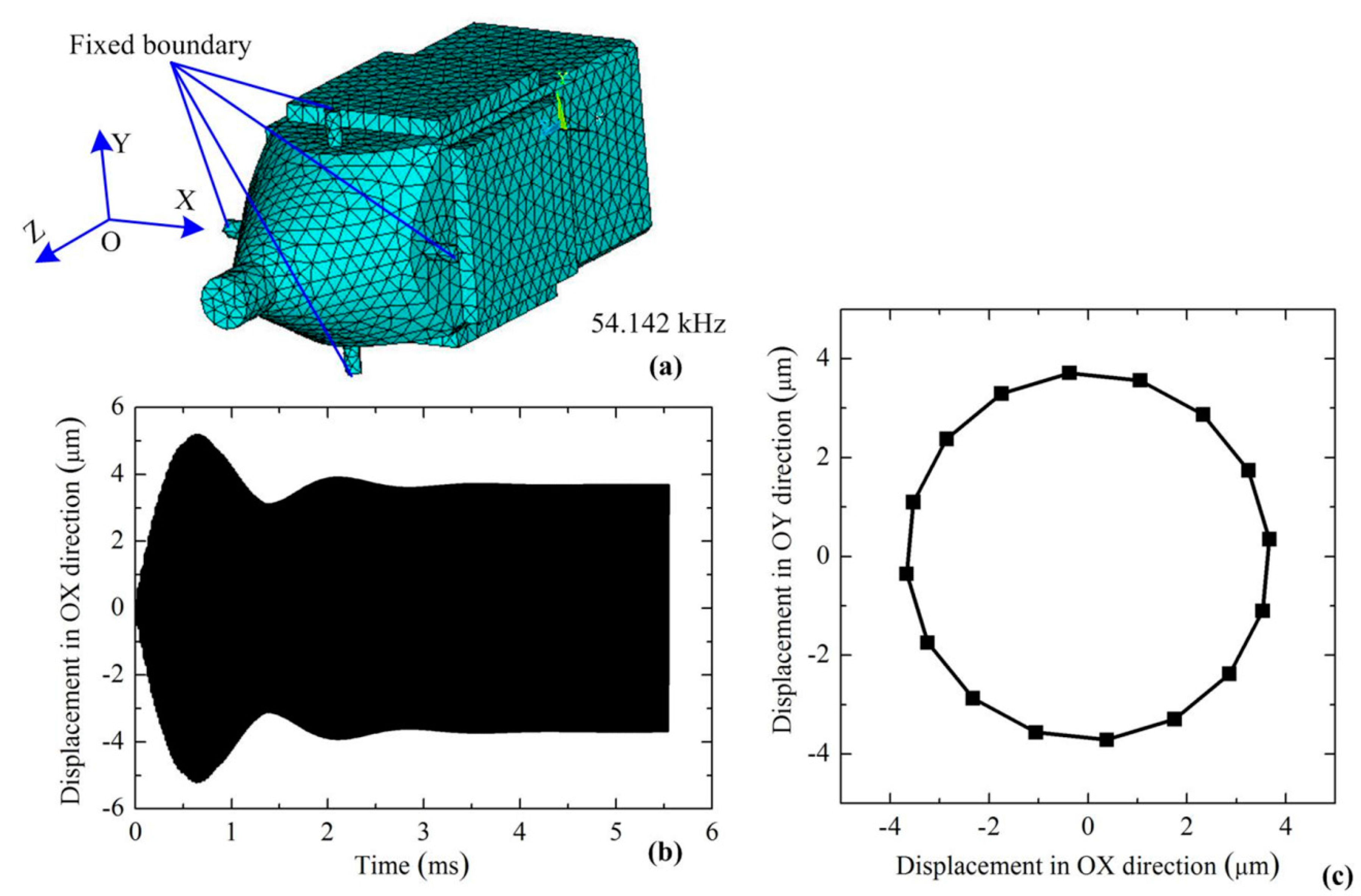
Figure 6a gives another FEM model, in which four bolts were added, and fixed boundary conditions were applied on the ends of the bolts. The first bending resonance frequency was calculated to be 54.142 kHz by modal analysis, which experienced a little increase of 0.38 kHz. The vibration characteristic of the driving tip by transient analysis is shown is
Figure 6. Under the resonance frequency, the new model with fixed boundaries achieved higher transverse displacement of about 3.76 μm. Thus, the clamping of the transducer causes the increases of both resonance frequency and vibration amplitude. These two factors can lead to an improvement of the vibration velocity of the driving tip.
Figure 5.
Movement of the end tip by transient analysis: (a) FEM model of the transducer; (b) the displacement response of the driving tip along OX direction; (c) the steady motion of the driving tip in XOY plane.
Figure 5.
Movement of the end tip by transient analysis: (a) FEM model of the transducer; (b) the displacement response of the driving tip along OX direction; (c) the steady motion of the driving tip in XOY plane.
Figure 6.
Movement of the end tip under fixed boundary condition: (a) FEM model; (b) the displacement response along OX direction; (c) the steady motion in XOY plane.
Figure 6.
Movement of the end tip under fixed boundary condition: (a) FEM model; (b) the displacement response along OX direction; (c) the steady motion in XOY plane.
5. Fabrication and Measurement
In the proposed piezoelectric motor, three bending transducers are used together to rotate the rotor; three transducers are required to have the same resonance frequency and the same vibration velocity. However, the manufacturing and assembly errors may cause differences. It can be easily understood that these discrepancies must make the three driving tips conflict with each other, which may result in the decrease of the output speed and torque. To solve this problem, six bending transducers were fabricated initially, and the three ones with closest resonance frequencies would be selected for the prototype. In the assembly process of the transducer, the contact surfaces between the PZT plates and the beam were smeared with epoxy adhesive uniformly; then we used precision parallel-jaw vice to clamp the PZT plates on the beam for about 12 h to accomplish the solidification.
Figure 7 shows the prototypes of the bending transducers and the final motor.
Figure 7.
The prototype: (a) the bending transducers; (b) the final motor.
Figure 7.
The prototype: (a) the bending transducers; (b) the final motor.
Then, we used a scanning laser Doppler vibrometer (PSV-400-M2, Polytec, Waldbronn, Germany) to obtain the first bending resonance frequencies of the six transducers. During the measurement, the upper surface and the side surface of the transducer were selected separately for the test of the two first bending modes and the transducers were fixed by a clamp.
Table 1 and
Figure 8 give the tested results. Among the 12 tested frequencies, the minimum and maximum are about 52.646 kHz and 53.218 kHz. Although these tested frequencies are obviously lower than the calculated one, each transducer has very close vertical and horizontal frequencies. Furthermore, the fist bending vibration is the only mode excited in the frequency region from 0 kHz to 80 kHz, as shown by the vibration velocity response spectrums of transducer-1. Finally, transducer-1, transducer-5 and transducer-6 were selected for the motor prototype. It should be noted that the bending resonance frequencies of the transducers listed in
Table 1 were obtained under bolt-clamped boundary condition. When the transducers were released from the clampers, their resonance frequencies exhibited decreases of about 0.3 kHz, and the vibration amplitudes of the driving tips also showed minute decreases. These tested results agreed well with the FEM calculation ones.
Table 1.
The tested first bending resonance frequencies.
Table 1.
The tested first bending resonance frequencies.
| Transducers | 1 | 2 | 3 | 4 | 5 | 6 |
|---|
| Vertical bending frequency (kHz) | 53.063 | 52.915 | 52.843 | 52.840 | 53.187 | 53.069 |
| Horizontal bending frequency (kHz) | 53.134 | 52.734 | 52.646 | 52.906 | 53.218 | 53.168 |
Figure 8.
Vibration measurement result of transducer-1: (a) vibration shape of vertical bending; (b) vibration velocity response spectrum of vertical bending; (c) vibration shape of horizontal bending; (d) vibration velocity response spectrum of horizontal bending.
Figure 8.
Vibration measurement result of transducer-1: (a) vibration shape of vertical bending; (b) vibration velocity response spectrum of vertical bending; (c) vibration shape of horizontal bending; (d) vibration velocity response spectrum of horizontal bending.
Figure 9a shows the experiment set-up of the rotary piezoelectric motor. Output torque was applied by a weight through a string wound on the rotor, and a tachometer was used to measure the speed. During the experiments, the working frequency was set as 53.2 kHz, this value was a little higher than the tested one as the preload between the rotor and the driving tip increased the resonance frequency. The amplitudes of the sine and cosine voltages were changed to obtain their effects on the output speed and torque. Firstly, the no-load speed and maximum torque were tested by changing the sine and cosine voltages synchronously; the sine and cosine voltages were used to excite the horizontal and vertical bending vibrations respectively, as shown in
Figure 1d. Then, cosine voltage was set with amplitude of 160 V
p-p, and we only changed the amplitude of the sine voltage to obtain the no-load speed and maximum torque. The measured results are plotted in
Figure 9.
The increases of the exciting voltages cause obvious improvements in the output speed and torque. However, the two control methods exhibit different characteristics: the synchronous adjustments of the two voltages bring a quicker and nonlinear change on both speed and torque, while a slower and linear speed control is realized by changing horizontal voltage under constant vertical voltage. For the classic rotary piezoelectric motor driving by bending traveling wave, the amplitude of the two exciting voltages must be changed together to realize the speed and torque control. However, we can control the proposed motor with a new and better method, which is a significant difference and improvement. Furthermore, the prototype achieves maximum no-load speed of 53.3 rpm and maximum torque of 27 mN·m under exciting voltages of 160 Vp-p, and the output speed decrease linearly as the increasing of the added weight.
Figure 9.
The mechanical output performance of the prototype: (a) the experiment set-up; (b) plot of the no-load speed versus the sine and cosine voltages; (c) plot of the maximum torque versus the sine and cosine voltages; (d) plot of the no-load speed versus the sine voltage under cosine voltage of 160 Vp-p; (e) plot of the maximum torque versus the sine voltage under cosine voltage of 160 Vp-p; (f) plot of the speed versus the torque under different voltages.
A comparison between the proposed piezoelectric motor and a previous work [
21] with similar operating principle is listed in
Table 2. Both these two motors achieved rotary driving by the superimposing of two first bending vibrations of a beam, but they operated in different ways. In He’s work, the end surface of the beam served as the driving part, which meant that the axial displacement was used to overcome the preload and the circumferential displacement was used for the push. However, we have not used the axial displacement of the driving tip in the proposed motor: the preload is overcome by the vertical displacement of the tip while the rotor is pushed by the horizontal one. For the bending of a beam, it is common sense that the transverse displacement of the end tip is bigger than the axial one. Thus, our work has achieved obvious improvement on the torque density (torque weight ratio).
Table 2.
Comparison between the proposed motor and a previous work.
Table 2.
Comparison between the proposed motor and a previous work.
| Parameters | The previous motor by He [21] | The proposed motor |
|---|
| Exciting frequency (kHz) | 23.5 | 53.2 |
| Weight of the stator (g) | 2.9 | 35.4 |
| Maximal speed (rpm) | 400 | 53.3 |
| Maximal torque (mN·m) | 0.3 | 27 |
| Torque density (mN·m/g) | 0.103 | 0.763 |
Surely, the proposed bending transducer can also be used for linear actuating. We also tested its output performance on a linear platform, as shown in
Figure 10a. The three transducers were measured individually under working frequency of 53.2 kHz and voltage of 160 V
p-p. Their output speeds under different thrusts are shown in
Figure 10b. A no-load speed of 159.6 mm/s and a maximum thrust of 0.29 N were achieved by one transducer. If linear speed and thrust are converted into a rotary one, the three transducers can get a no-load speed of 38.1 rpm and a maximum torque of 35 mN·m as the diameter of the rotor is about 80 mm. Thus, the proposed transducer can get larger output force in linear driving, but higher speed for rotary actuating.
Figure 10.
Plot of the thrust force versus the speed of the transducers.
Figure 10.
Plot of the thrust force versus the speed of the transducers.


 ,
, 


