1. Introduction
Because of technological advancement and product innovation, people increasingly demand a high quality of life, especially regarding optomechanical system products. Therefore, people desire products featuring adjustable sizes and high image quality, such as telescopes [
1,
2], mobile lenses [
3,
4], pinhole cameras [
5,
6], and medical endoscopes [
7].
Based on specification requirements, the optical designer typically builds a lens structure with a constant effective focal length (EFL) initially, to facilitate predicting the highest-quality image during optimization simulations. When an object must be enlarged or shrunk according to different distances, the user can only approximate this by physically moving a lens with a constant EFL close to, or far away from, the object involved. Therefore, a zoom lens is extremely effective for taking photos of objects at different distances.
Zoom lenses with multiple EFLs are built, enabling lens systems to acquire objects at various distances [
8,
9]. Zoom systems are highly complex optical systems [
10,
11]. A traditional zoom lens [
12] is composed of four parts, namely a front lens group, a zoom lens group, a back lens group, and a compensating lens group. The front lens group and back lens group are fixed, but the location of the elements of the zoom lens group and compensating lens group can be adjusted to vary the EFL and refine the image quality on an image plane. Only one zoom lens group is applied in a traditional zoom lens to enable the use of multiple EFLs. In [
13], the intermediate optics concept was used to design a zoom lens layout and a zoom lens with a 9× ratio, which was achieved by cascading two subsystem groups with a 3× zoom lens.
In a traditional optical system, field lenses are used to collect edge rays and transmit them through another lens; thus, the optical power at the edge of an optical beam is not easily diverted when edge rays leave the lens [
14,
15]. The droplet shape and location of liquid lenses can be adjusted reversibly, enabling the focal length and position of the lens to be tuned by adjusting the voltage applied to a set of electrodes [
16,
17]. Hence, liquid lenses can replace complex lens combinations to reduce the total length of optomechanical systems. But the liquid thickness varies non-linearly with the radius of the interface; it’s very difficult to optimize a real liquid lens using commercial optical design software directly [
18].
There is also a point for attention while using liquid lens as compensating lens. First, the negative power of zoom optics limitations make field curvature becomes inherent, which seriously degrades the system modulation transfer function (MTF). Second, the abbe numbers of materials of liquid optics are not similar to those of extra dispersion optical materials and consequently, axial chromatic aberration becomes severe. Third, the chief rays may be vastly bent to fit the limited bore of liquid optics; but this may complicate the optical design, due to aberrations [
19].
The research [
13] a zoom lens comprising lens elements of a small diameter was designed by applying intermediate optics to distribute optical power into two zoom subsystems. Therefore, the diameter of the lens element for the zoom lens with intermediate optics is smaller than that of the traditional zoom lens. Moreover, the proposed zoom subsystems can respectively compensate for their aberrations because of the nonlinear compensation of the zoom lens group in the zoom lens system. Cascading these zoom subsystems increases the zoom ratio for the overall zoom lens system.
This study proposes using a liquid lens as a compensating lens and combining it with a 9× zoom lens. The CODE V built-in optimization method was used to determine the process parameters. The proposed technology can be used to improve the total MTF and reduce the Petzval surface curvature (PTZ) of zoom lenses.
2. Basic Theory of Optical Design
The proposed design consists of a liquid lens used to achieve a 9× zoom ratio based on the structure described in [
13]. The intermediate optics concept was applied to design the layout of the zoom lens; two subsystem groups were cascaded with a 3× zoom lens to achieve a 9× zoom ratio. In the proposed optical system, the compensating liquid lens is placed at the final position in the second subsystem, a 3× zoom lens group.
A real image (e.g., intermediate image) is observed between two zoom lens groups. The effect of the intermediate image enables the power of the two groups of lenses to function independently, wherein a lower power in the front lens group can be assigned to alleviate the diameter of the lens elements. The traditional zoom ratio is defined by Mtotal = ftele/fwid, where fwid is the EFL with wide-angle and ftele is the EFL for the telescope.
Figure 1 illustrates the total zoom ratio for an intermediate image.
Figure 1.
The illustration of zoom ratio with relay image (M1 is first group of zoom lens and M2 is second group of zoom lens).
Figure 1.
The illustration of zoom ratio with relay image (M1 is first group of zoom lens and M2 is second group of zoom lens).
The method of cascading two lens systems has been used in developing various applications. Several applications, such as afocal optics, can be used to realize an entire lens system. Two well-known afocal lens designs are the telescope and microscope, two lens systems that cannot be used to create an image without cascading an additional image system, similar to the function of the human eye. A telescope is used to view an object at long distances, in contrast to a microscope, which is employed when an object must be viewed in a larger size to observe details. These two lens systems produce a virtual image, which is the object of the additional image system. The additional image system must catch the virtual image to form the image at a focal plane. However, ensuring that the pupils match is a challenge; that is, the exit pupil of the front afocal lens must be the same as the entrance pupil of the second image system. When the two systems are combined, the pupil match is crucial because it is related to the F-number.
The size and diagonal of the CCD are 1/2.7” and 6.592 mm, respectively. All design specifications are show in
Table 1. The maximum field angle of the proposed zoom lens is 50°; accordingly, the semifield angle is 25°. When the image high and field angle have been determined, the relationships among the EFL, image high, and field angle can be defined as
where
E is the EFL,
H is the image high, and θ is the semifield angle. Equation (1) can be used to determine that the EFL is 7.068 mm at the maximum field angle. Because the zoom ratio of the proposed zoom lens is 9×, the EFL of a telescope in which the proposed lens is applied is 63.612 mm. The specifications of the 9× zoom lens are provided in
Table 1.
Table 1.
Specifications of the 9× zoom lens.
Table 1.
Specifications of the 9× zoom lens.
| Initial Conditions of Design | P.S |
|---|
| Image high | 3.296 mm | R.G.B |
| light weighting | Photonics 5 with 550 nm |
| Focal length | 7.068 mm~63.204 mm |
| Zoom ratio | 9× |
| F# | 3.2~5.6 | Zoom 1 |
| Zoom 2 |
| Zoom 3 |
| Zoom 4 |
| Zoom 5 |
| Zoom 6 |
| Overall length | 139.3565~140.2137 mm | |
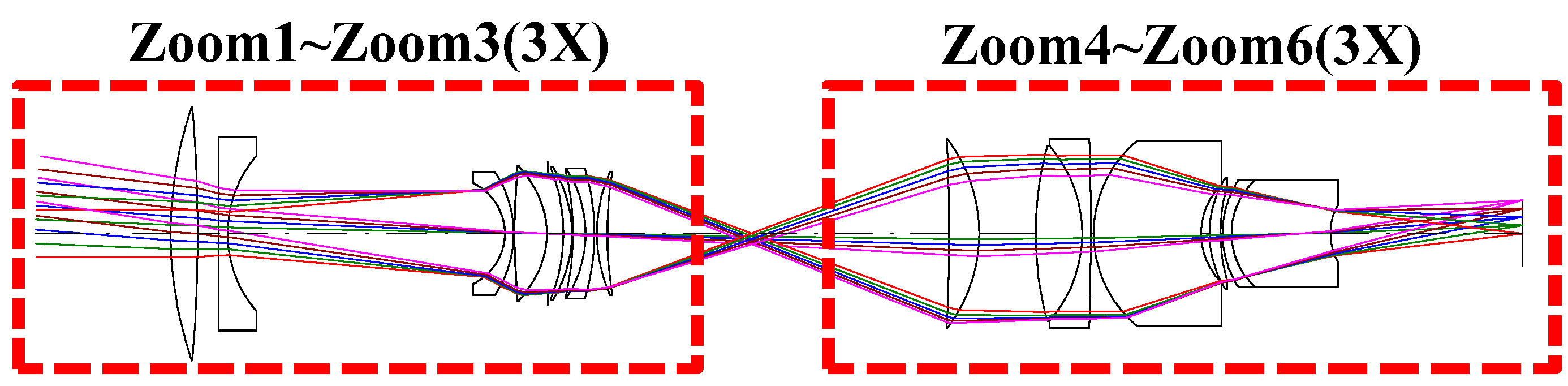
The proposed intermediate optics structure consists of a front zoom lens subsystem and back zoom lens subsystem, as shown in
Figure 2. The front zoom lens involves applying Zoom 1–Zoom 3 to realize a zoom ratio of 3×; its f number ranges from 3.2 to 4.4. The back zoom lens involves using Zoom 4–Zoom 6 to implement a zoom ratio of 3×; its f number ranges from 4.4 to 5.6. The proposed zoom lens system was designed using a 9× zoom lens by cascading the front zoom lens at a 3× zoom ratio, and the back zoom lens at a 3× zoom ratio. Before the two subsystems were combined, the front zoom lens was designed as the infinity conjugate and the back zoom lens was designed as the finite conjugate.
Figure 2.
The structure of 9× zoom lens with intermediate optics image (The 3X means 3X optical zoom).
Figure 2.
The structure of 9× zoom lens with intermediate optics image (The 3X means 3X optical zoom).
The intermediate optics structure in the infinite conjugate system has the object located at infinity; its specification is shown in
Table 2. Under the same previous specification of image height and wavelength spectrum, the full-field angle is set at 50°. Because the proposed zoom lens system is symmetrical, the semi-field angle is 25°. According to Equation (1), the EFL is 7.068 mm for a wide-angle zoom. Because the zoom ratio of the front zoom lens is 3×, the EFL of the telescope structure is 21.204 mm. By contrast, the proposed front zoom lens is designed to be telecentric at an image-space to link the back zoom lens. In general, two methods in the optical software can be applied to implement the telecentric structure. The first method is to optimize the angle of the marginal ray approach to 0° at an image-space, wherein the ray is parallel to the optical axis. The second method is to optimize the location of the exit-pupil approach by setting it at infinity, allowing the ray to be parallel to the optical axis. The former method is applied in the proposed zoom lens design.
Table 2.
The specification of the front zoom lens.
Table 2.
The specification of the front zoom lens.
| Initial Conditions of Design | P.S |
|---|
| Image Height | 3.296 mm | |
| R.G.B. light weighting | Photonics 5 with 550 nm | |
| Focal Length | 7.068 mm~21.204 mm | |
| Zoom Ratio | 3× | |
| F# | 3.2~4.4 | ZOOM 1 7.068 mm F# 3.2 |
| ZOOM 2 14.136 mm F#3.8 |
| ZOOM 3 21.204 mm F#4.4 |
| Overall Length | <60 mm | |
| Optical Distortion | <3% | |
| Element/Group | 8 element | |
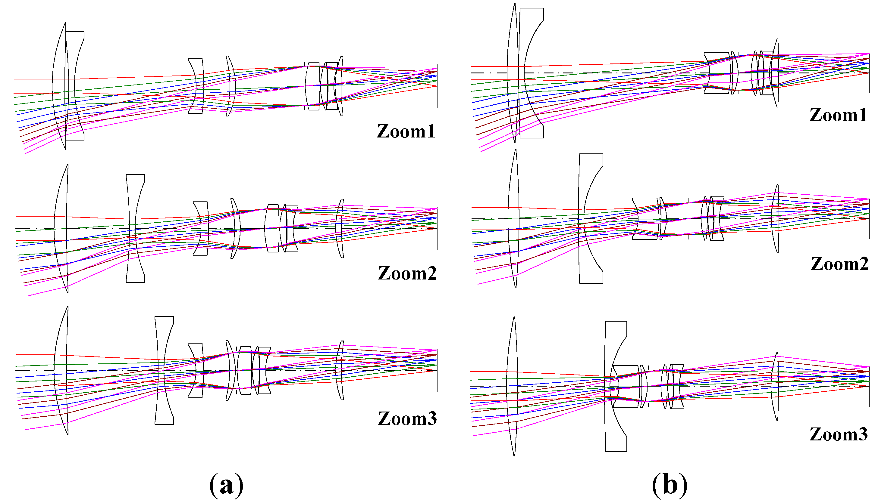
The intermediate optics system entails applying the telecentric concept to link the two pupils. The ray from the front zoom lens subsystem is parallel, incident to the back zoom lens subsystem. The second telecentric design is applied to implement the back zoom lens subsystem. In Code V, the location of the exit pupil of the front zoom lens is optimized from 28.281 mm to 1000 mm. After the optimization, the ray is parallel to the optical axis, as shown in
Figure 3.
Figure 3a shows that the location of the exit pupil is at 28.281 mm.
Figure 3b shows that the location of exit pupil is at 1000 mm.
Figure 3.
The structure of the front zoom lens with 3× zoom ratio (a) Non-telecentric structure; (b) Telecentric structure.
Figure 3.
The structure of the front zoom lens with 3× zoom ratio (a) Non-telecentric structure; (b) Telecentric structure.
The back zoom lens with intermediate optics is a finite conjugate system, in which the distance of the object is finite. Therefore, Code V is employed to optimize the distance of the object from infinity to 20 mm. Because the object (
i.e., intermediate image) must not be too close to the first surface of the back zoom lens, the distance is set at 20 mm in the proposed zoom lens system, as shown in
Table 3. The structure of the back zoom lens is shown in
Figure 4. The image height and wavelength spectrum are the same as those of the front zoom lens. The full-field angle is 17.67° for the semi-field angle to be 8.835° for a symmetrical structure. According to Equation (1), the EFL is 21.204 mm for a wide angle, and is 63.612 mm for the telescope, in the 3× zoom lens design.
Table 3.
The specification of the back zoom lens for overall zoom lens with 9× zoom ratio.
Table 3.
The specification of the back zoom lens for overall zoom lens with 9× zoom ratio.
| Initial Conditions of Design | P.S |
|---|
| Image Height | 3.296 mm | |
| R.G.B.light weighting | Photonics 5 with 550 nm | |
| Focal Length | 21.204 mm~63.612 mm | |
| Zoom Ratio | 3× | |
| F# | 4.4~5.6 | ZOOM 1 21.204 mm F#4.4 |
| ZOOM 2 42.408 mm F#5 |
| ZOOM 3 63.612 mm F#5.6 |
| Overall Length | <68.168 mm | |
| Optical Distortion | <3% | |
| Element/Group | 7 element in 6 group | |
Figure 4.
The structure of back zoom lens with 3× zoom ratio.
Figure 4.
The structure of back zoom lens with 3× zoom ratio.
After the two zoom lens systems were linked, the lens structure of the combined system was different from that of the separate systems. This is because some degree of change in the optical power occurs when the two systems are combined. To preserve the zoom ratio at 9×, Code V must be applied to optimize the EFL, maintaining both the front and back zoom lens at a value of 3×. Consequently, a 9× zoom lens with intermediate optics can be obtained.
Figure 5 illustrates the MTF and
Figure 6 shows the spot diagram.
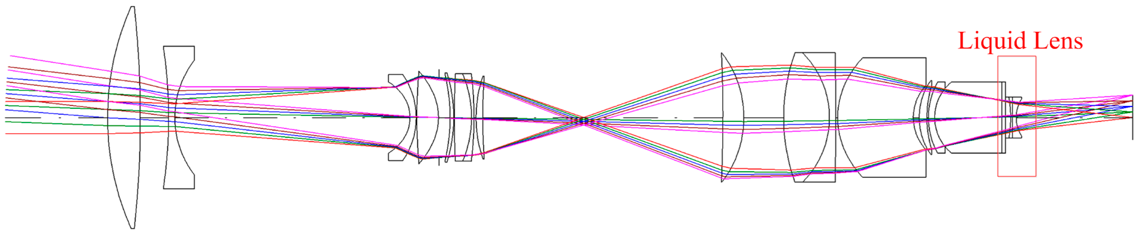
The proposed compensated intermediate optics structure featuring a 9× zoom ratio is shown in
Figure 7.
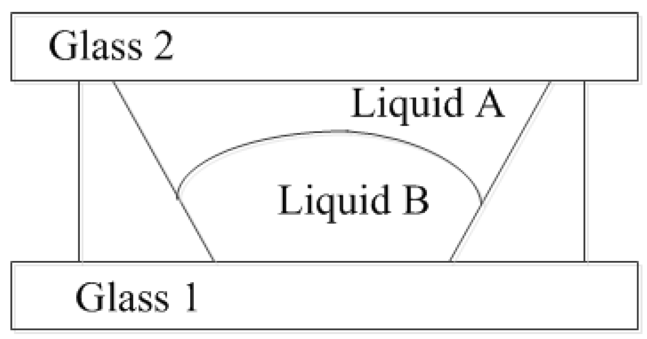
Varioptic provided the liquid lens type specifications [
20]. As shown in
Figure 8, the liquid lens is composed of a single glass material (Glass 1 = Glass 2) and Liquid A and Liquid B.
Table 4 and
Table 5 show the index of refraction
versus the wavelength.
Figure 5.
The modulation transfer function (MTF) of 9× zoom lens for intermediate optics design (a) 7.068 mm_F/#3.2 (Zoom 1); (b) 63.612 mm_F/#5.6 (Zoom 6).
Figure 5.
The modulation transfer function (MTF) of 9× zoom lens for intermediate optics design (a) 7.068 mm_F/#3.2 (Zoom 1); (b) 63.612 mm_F/#5.6 (Zoom 6).
Figure 6.
The spot diagram of 9× zoom lens for intermediate optics design. (a) 7.068 mm_F/#3.2 (Zoom 1); (b) 63.612 mm_F/#5.6 (Zoom 6).
Figure 6.
The spot diagram of 9× zoom lens for intermediate optics design. (a) 7.068 mm_F/#3.2 (Zoom 1); (b) 63.612 mm_F/#5.6 (Zoom 6).
Figure 7.
The compensated structure of the liquid lens featuring a 9× zoom ratio.
Figure 7.
The compensated structure of the liquid lens featuring a 9× zoom ratio.
Figure 8.
Liquid lens model.
Figure 8.
Liquid lens model.
Table 4.
Index of refraction of the glass versus wavelength.
Table 4.
Index of refraction of the glass versus wavelength.
| Wavelength (mm) | Index |
|---|
| 700 | 1.5150 |
| 650 | 1.5164 |
| 590 | 1.5187 |
| 550 | 1.5206 |
| 480 | 1.5252 |
| 430 | 1.530 |
Table 5.
Liquid index at 20 °C.
Table 5.
Liquid index at 20 °C.
| Wavelength (mm) | PC100 (Liquid A) | H100 (Liquid B) |
|---|
| 400 | 1.41178 | 1.51297 |
| 448 | 1.40729 | 1.50340 |
| 489 | 1.40451 | 1.49772 |
| 541 | 1.40180 | 1.49250 |
| 589.3 | 1.39988 | 1.48894 |
| 654.6 | 1.39791 | 1.48535 |
| 703 | 1.39671 | 1.48332 |
3. Comparison and Simulation Results
The traditional zoom lens structure is based on a front group with a fixed structure, zoom group, back group with a fixed structure, and compensated group. Using a liquid lens as a compensating lens enables complex optical systems to be improved easily, because the focal length of liquid lenses can be varied by adjusting the applied voltage, and, thus, zoom systems featuring various focal lengths and zoom ratios can be developed. The liquid lens parameters after CODE V optimization are listed in
Table 6. Two-dimensional plots of the optimized structure of the proposed lens are shown in
Figure 9.
Figure 10 and
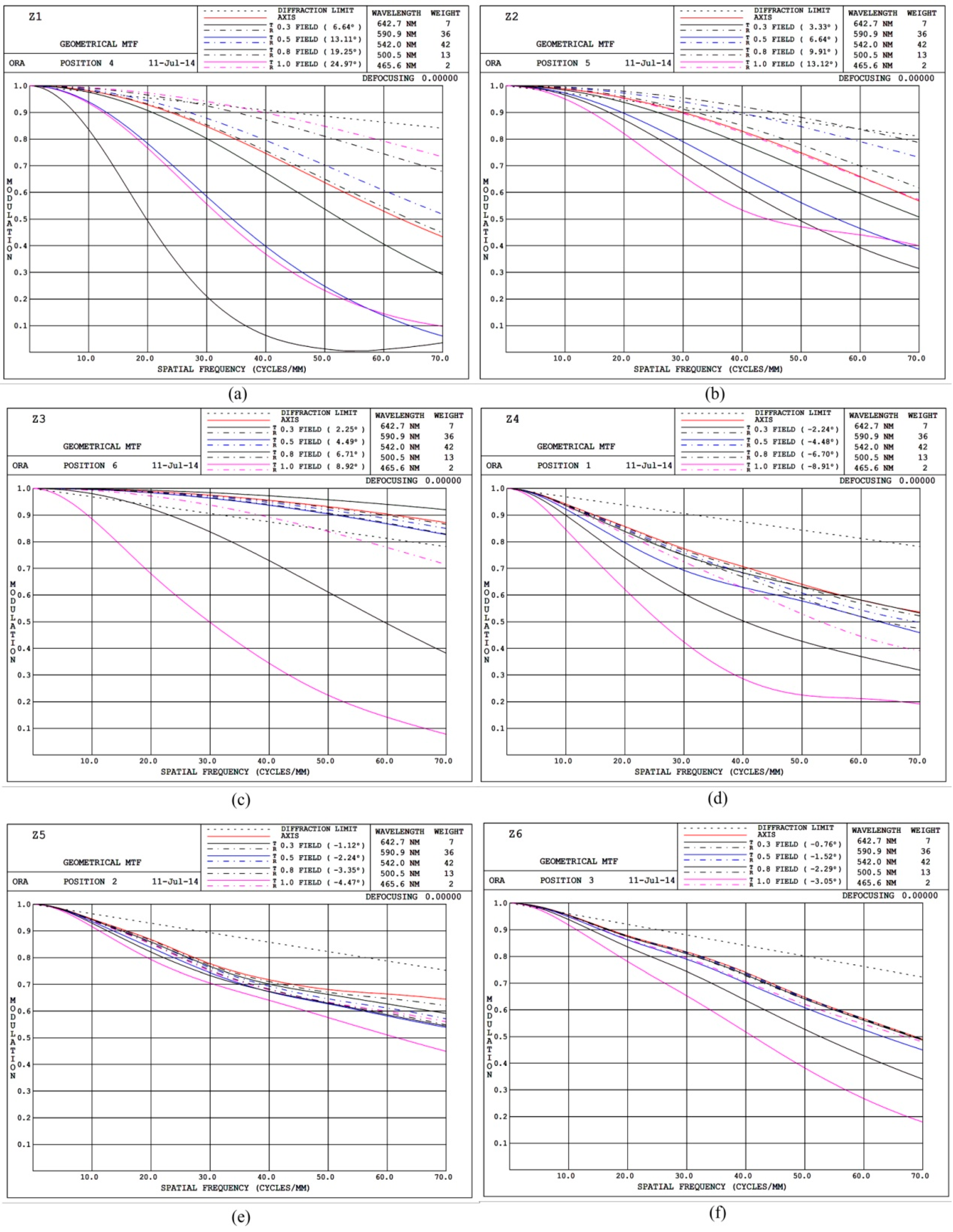
Figure 11 respectively show the MTFs and spot plots of the proposed lens.
Figure 9.
Two-dimensional plots of the optimized design: (a) Zoom 1; (b) Zoom 2; (c) Zoom 3; (d) Zoom 4; (e) Zoom 5; (f) Zoom 6.
Figure 9.
Two-dimensional plots of the optimized design: (a) Zoom 1; (b) Zoom 2; (c) Zoom 3; (d) Zoom 4; (e) Zoom 5; (f) Zoom 6.
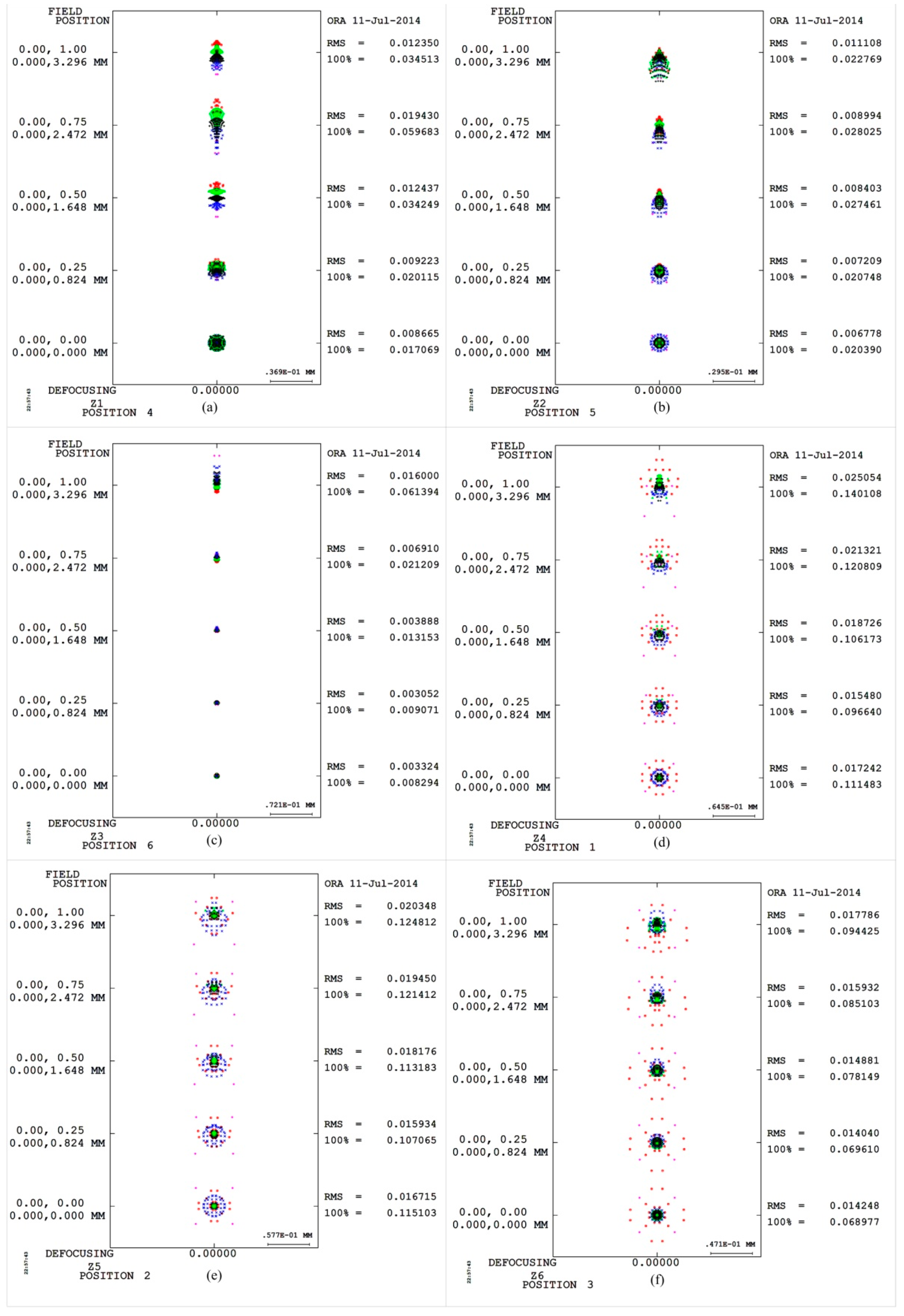
Comparing conventional intermediate optics design of
Figure 5 with proposed compensating lens scheme of
Figure 10, the average MTF curves are superior than conventional intermediate optics design, hence the better image performance can be obtained. Besides, the third aberrations in the proposed zoom structure are also improved of smaller spot size as shown in
Figure 6 and
Figure 11.
Figure 10.
MTFs of the proposed lens: (a) Zoom 1; (b) Zoom 2; (c) Zoom 3; (d) Zoom 4; (e) Zoom 5; (f) Zoom 6.
Figure 10.
MTFs of the proposed lens: (a) Zoom 1; (b) Zoom 2; (c) Zoom 3; (d) Zoom 4; (e) Zoom 5; (f) Zoom 6.
Figure 11.
Spot plots of the proposed lens: (a) Zoom 1; (b) Zoom 2; (c) Zoom 3; (d) Zoom 4; (e) Zoom 5; (f) Zoom 6.
Figure 11.
Spot plots of the proposed lens: (a) Zoom 1; (b) Zoom 2; (c) Zoom 3; (d) Zoom 4; (e) Zoom 5; (f) Zoom 6.
Table 6.
Liquid lens parameters after CODE V design.
Table 6.
Liquid lens parameters after CODE V design.
| Lens parameters | Lens Aperture | Effective Focal Length |
|---|
| Zoom areas | |
|---|
| Z1 | 3.2 | 7.0680 |
| Z2 | 3.8 | 14.1359 |
| Z3 | 4.4 | 21.2039 |
| Z4 | 4.4 | −14.4675 |
| Z5 | 5.0 | −28.9501 |
| Z6 | 5.6 | −43.4603 |
In general, optical design with a liquid lens element is difficult to optimize, mainly because of the extreme spherical aberration, coma aberration and the axial chromatic aberrations. These severe axial aberrations are generated mainly from oblique incident rays close to the liquid lens element. In the study, first, we demonstrate a methodology for the optical design of intermediate zoom optics, which may not only mitigate some aberration problems but also further reduce the volumetric size of the 9× zoom system. Second, in this newly developed design, the liquid lens technology used as compensating lens to reduce the error of effective focal length and several aberrations especially on TCO, LAT and PTZ, thanks to the assistance of a new design methodology for liquid lens elements in particular.
The simulation results revealed that the performance of the proposed lens design is superior to the standard 9× zoom lens design; the zoom ratios are listed in
Table 6, and an MTF comparison is in 40 1p/mm. In
Table 7, we can find the average performance of TCO, LAT, PTZ and MTF are also improved in the proposed compensating liquid lens technology, but got the worse performance in SA. This is because the optical design is a tradeoff between all aberrations.
Table 7.
Percentage comparison between the proposed lens and a standard 9× zoom lens.
Table 7.
Percentage comparison between the proposed lens and a standard 9× zoom lens.
| Zoom | SA | TCO | LAT | PTZ | MTF |
|---|
| Zoom 1 | 4.57% | 48.7% | 4.56% | 2.68% | −34% |
| Zoom 2 | −241.92% | −163.7% | 27.7% | −5.7% | 2.23% |
| Zoom 3 | −1452.2% | −213.36% | 50.01% | 10.92% | 4.86% |
| Zoom 4 | −212.052% | 35.41% | 12.47% | 1.85% | 3988% |
| Zoom 5 | −2345.1% | −13.05% | 19.51% | 1.85% | −15.4% |
| Zoom 6 | −68.96% | 47.12% | 23.37% | 1.85% | −38.5% |


