Review

Status of the High Average Power Diode-Pumped Solid State Laser Development at HiLASE

by
Ondřej Novák
*,
Taisuke Miura
,
Martin Smrž
,
Michal Chyla
,
Siva Sankar Nagisetty
,
Jiří Mužík
,
Jens Linnemann
,
Hana Turčičová
,
Venkatesan Jambunathan
,
Ondřej Slezák
,
Magdalena Sawicka-Chyla
,
Jan Pilař
,
Stefano Bonora
,
Martin Divoký
,
Jakub Měsíček
,
Alina Pranovich
,
Pawel Sikocinski
,
Jaroslav Huynh
,
Patricie Severová
,
Petr Navrátil
,
David Vojna
,
Lucie Horáčková
,
Klaus Mann
,
Antonio Lucianetti
,
Akira Endo
,
Danijela Rostohar
and
Tomáš Mocek
add Show full author list remove Hide full author list
HiLASE Centre, Institute of Physics, Academy of Sciences of the Czech Republic, Za Radnicí 828, Dolní Břežany 252 41, Czech Republic
*
Author to whom correspondence should be addressed.
Appl. Sci. 2015, 5(4), 637-665; https://doi.org/10.3390/app5040637
Submission received: 31 July 2015 / Revised: 2 September 2015 / Accepted: 6 September 2015 / Published: 25 September 2015
(This article belongs to the Special Issue Diode-Pumped, Ultra-Short Pulse Lasers)

Abstract

:
An overview of the latest developments of kilowatt-level diode pumped solid state lasers for advanced applications at the HiLASE Centre is presented. An overview of subcontracted and in-house-developed laser beamlines is presented. The aim of development is to build kW-class beamlines delivering picosecond pulses between 1- and 100-kHz repetition rates and high-energy nanosecond pulses at 10 Hz. The picosecond beamlines are based on Yb:YAG thin-disk amplifiers and chirped pulse amplification. The current status of the beamlines’ performance is reported. The advantages of zero-phonon line and pulsed pumping are demonstrated with respect to efficiency, thin disk temperature and beam quality. New diagnostics methods supporting the high average power lasers’ development, such as the high-resolution spectroscopy of Yb-doped materials, in situ thin disk deformation measurements, single-shot M2 measurement, realization of wavefront correction by a deformable mirror and the laser performance of a new mixed garnet ceramics, are described. The energetic, thermal and fluid-mechanical numerical modeling for the optimization of the multi-slab amplifiers is also described.

Graphical Abstract

1. Introduction

High average power lasers are needed to increase the processing speed in industrial applications and to increase the signal-to-noise ratio in many scientific applications. Typically, the output of a weak oscillator is increased in a single or multiple amplifiers, which is denoted as the master oscillator power amplifier (MOPA). In short-pulse laser systems, the chirped pulse amplification (CPA) is utilized, where the MOPA procedure involves stretching the pulses prior to the amplification and a subsequent compression of amplified pulses [1]. In recent years, the number of diode-pumped solid state lasers has dramatically increased thanks to their high efficiency, reliability, flexibility and compactness [2]. Increasing the average power of lasers needs active laser media with a low quantum defect, efficient heat removal and good overlap between their absorption line and pump radiation. In short-pulse high average power lasers, the popular Nd:YAG (neodymium-doped yttrium aluminium garnet) active medium has been replaced by Yb:YAG (ytterbium-doped yttrium aluminium garnet). Compared to the Nd:YAG, the Yb:YAG has a lower quantum defect and broader emission bandwidth, allowing for the generation of picosecond or even femtosecond pulses. The other Yb-doped materials used in lasers are, e.g., Yb:LuAG (lutetium aluminum garnet), Yb:YLF (yttrium lithium fluoride), Yb:CaF2 (calcium fluoride), Yb:KYW (potassium yttrium tungstate), Yb:KGW (potassium gadolinium tungstate), Yb:CALGO (Yb:CaAlGdO4) and Yb:glass, especially in the form of optical fibers [3,4,5,6,7].
The efficient heat removal is achieved by the specific gain material geometry enabling large heat flow from the laser material to a heat sink. Among the most popular geometries are fiber [8], thin-disk [9] and Innoslab concepts [10,11]. These geometries are mainly used for moderate (kHz) and high (MHz) pulse repetition rates of laser amplifiers. In fibers the radial heat flow removes the heat. The maximum pulse energy is limited by the small fiber aperture. A thin disk works as an active mirror with cooling from the back side. Small disk thickness in order of hundreds of micrometers enables very efficient heat removal by axial heat flow, but results in a small gain per bounce. The Innoslab concept uses a thin slab with side cooling. A folded beam path is used, and the beam size is increased at each pass. Higher pulse energies (>1 J) at lower repetition rates (10 Hz, 100 Hz) have been achieved by using conventional designs [12], thick disks [13,14,15,16], total reflection active mirrors (TRAM) [17] or multi-slabs [18,19]. Some of them employ operation at cryogenic temperatures using the advantages of higher thermal conductivity and higher gain at low temperatures [20,21].
In this paper, we present a review of the current status of high average power diode-pumped lasers being developed at the HiLASE Centre. First, the laser facility and its aims are introduced. The description of the latest results of the thin disk-based regenerative amplifiers follows. The development is supported by several diagnostic and optimization methods, developed at the HiLASE, that are mentioned in the last section.

2. HiLASE Centre

The HiLASE (acronym of High average power pulsed LASErs), the Czech National R&D Centre, focuses on the development of the next generation of high repetition rate diode-pumped solid state lasers. Such laser systems will find applications in the high-tech industry, scientific laboratories and large laser, infrastructures such as ELI (Extreme Light Infrastructure) [22] or HiPER (The High Power laser for Energy Research project) [23]. To cover a wide variety of applications, several laser systems of kilowatt-level average power will be available for users from scientific and industrial communities at the HiLASE Centre. The systems are depicted in Figure 1. The lasers are based on two concepts of efficient heat removal from the laser active medium: first, the thin-disk geometry aiming for pulses of about a 2-ps pulse width at repetition rates between 1 and 100 kHz; second, the cryogenically-cooled multi-slab amplifier that will generate nanosecond pulses of a 100-J pulse energy at a 10-Hz repetition rate.
Figure 1. Overview of the laser beamlines at the HiLASE (High average power pulsed LASErs) Centre. The targeted parameters are presented.
Applsci 05 00637 g001
The future use of these lasers includes, among others, several prospective applications (Figure 2). The high repetition rate beamlines (1–100 kHz) will be used, e.g., for extreme ultraviolet (EUV) generation from gas jets or tin targets. The EUV wavelength region is important for a new generation of lithography, metrology and microscopy in the water window. Wavelength conversion to UV and mid-IR will be incorporated, as well, to spread the application potential to electron photo emission from a photocathode or advanced modification of dielectrics, respectively. In many industrial applications, the high average power ultrafast lasers are of great interest for a variety of applications, e.g., interesting capabilities for multiple beam processing, which would significantly increase processing speed, are supported by new developments in diffractive optics elements [24] and polygonal scanners, as well. The pulses of joule-level energy and more (10–1000 Hz) are intended for laser-induced damage threshold measurements, non-destructive laser adhesion tests and laser shock peening.
Figure 2. Application potential of the laser systems soon available at HiLASE R & D Laser Centre (prospective applications for future upgrades in blue) [25]. EUV, extreme ultraviolet; BEUV, beyond EUV; FEL, free-electron laser; LIDT, laser-induced damage testing.
Applsci 05 00637 g002

3. Kilowatt-Class Picosecond Thin-Disk Lasers

Applications, such as EUV generation, would benefit from picosecond lasers of high beam quality and average power from 100 W to more than 1 kW at a 1–100-kHz repetition rate [26]. Another application interesting for the industrial market that would profit from lasers of these parameters is processing of carbon fiber-reinforced plastics [27]. The thin-disk laser concept can meet all of these demanding requirements with high efficiency and is suitable for diode-pumped solid state lasers. Figure 3 shows the scheme of the thin-disk laser concept [9,28]. The laser gain media has the shape of a thin disk. The front surface of the thin disk is anti-reflection coated, and the back surface is high-reflection coated, both coatings functional for the laser and pump wavelengths. Thus, the thin disk can be used as an active mirror. The back surface is bonded to a heat sink, which is most often water cooled. The heat sink is made from material with high thermal conductivity, such as a copper-tungsten (CuW) alloy or diamond. The heat is removed from the thin disk mainly by axial heat flow thanks to its large surface-to-volume ratio. Thermal lensing, mechanical stresses and nonlinear effects experienced by a laser pulse in the active material are lower compared to the bulk arrangements. Further, the low transverse temperature gradient minimizes transversal thin disk deformations, and a high quality beam, close to the fundamental mode, can be produced. The fundamental mode is characterized by the ability to be focused to the smallest spot with a certain lens and initial beam diameter. A very small spot size diameter, in order of 10 µm, is crucial for some applications. On the other hand, very small thickness causes small single-pass gain and small pump light absorption. Therefore, materials with higher doping concentrations of active ions are used because higher doping increases gain and pump light absorption. The typical gain per reflection is between 1.1 and 1.4 [28]. Thus, if the thin disk is used for pulse amplification, a regenerative amplifier or a multi-pass amplifier needs to be used to provide high total gain. For the amplification of ultrashort (ps, fs) pulses, the CPA technique is incorporated.
Figure 3. Scheme of the thin disk-based laser head. HR, high reflective; AR, anti-reflection.
Applsci 05 00637 g003
The optical pumping by laser diodes of the wavelength matched to the absorption line of the active medium increases the overall efficiency and reduces the thermal load. The pump light is often fiber coupled for easy handling and homogenization of the beam of the laser diodes. The pump beam is collimated and imaged by a parabola mirror to the thin disk (see the Figure 3). Prisms and the parabola mirror retro-reflect the pump to the thin disk about 20–30 times, so over 90% of the pump power is absorbed. High pump power densities in the homogenously-pumped area are thus achieved. The output laser power can be increased in a simple way by increasing the diameter of the laser beam and pump spot size if the pump power density stays constant [9,28].
The typical materials used for thin disks are ytterbium-doped ones. Yb:YAG is the most common among them. Its quasi-three-level operation (at room temperatures and above) needs high pumping power density, which is obtained by diode pumping. The central laser wavelength is 1030 nm. Bands around 940 nm or 969 nm are used for pumping. The 940-nm pumping is less efficient due to the higher quantum defect, but at the same time less expensive pump diodes with an unstabilized wavelength can be employed. On the contrary, the 969-nm pumping offers a 1.5-times lower quantum defect and, so, reduces the heat generated in the laser medium. Thanks to direct pumping to the upper laser level, this scheme is called zero-phonon line pumping (ZPL). The zero-phonon line pumping reduces the heat generated in the laser medium. On the other hand, the absorption line width is only 2.8 nm, which requires the usage of more expensive wavelength-stabilized pump diodes with a narrow emission line [29,30,31,32].

Improvements of Thin Disk Laser Operations at HiLASE

Within the HiLASE thin disk laser development, several processes that improve laser operation have been systematically studied. First, we demonstrated that the pulsed pumping can improve the operation of the 1-kHz regenerative amplifier [33]. Further, we showed the advantages of zero-phonon line pumping, not only with respect to a lower thin disk temperature, a lower thin disk temperature difference between the lasing and non-lasing conditions [31], but also a lower amount of thin disk deformations [34,35,36]. The details will be described later in the text.

4. High Average Power Short-Pulse Thin Disk Lasers at HiLASE

4.1. Beamline A

The picosecond beamline with the highest pulse energy is designated as Beamline A. This beamline is subcontracted to Dausinger + Giesen company (Germany). The fiber laser oscillator is followed by a grating stretcher. The first amplification stage is a thin disk-based regenerative amplifier with 150 mJ of output energy [37]. The final amplification will be achieved in a multi-pass amplifier with a large aperture thin disk and wavefront correction. The pulse width behind the grating compressor should be less than 3 ps. The laser system will deliver 0.75 J of pulse energy at a repetition rate between 1 and 1.75 kHz, corresponding to the output average power of 0.75 kW and 1.3 kW, respectively.

4.2. Beamline B

The targeted output power of Beamline B is 500 W at a 1-kHz repetition rate with a pulse width of less than 2 ps. The development is subdivided into the development of the 100-W regenerative amplifier with a linear cavity and the main 500-W regenerative amplifier with a ring cavity.
The key limitation of the amplifier designs are the damage threshold values of the optical components. The design of the beamline took these damage threshold limitations into account. The most critical elements are the thin disk and Pockels cell crystals. The typical pump power density of the thin disk is limited to ~5 kW/cm2. The thin disk damage threshold is about 10 J/cm2 for 10-ns pulses. The square root scaling of the damage threshold fluence in dependence of the pulse width was used to determine the proper combination of the beam width and the stretched pulse width in order to stay below the damage threshold. If needed, the suggested design of the amplifier was optimized to stay with the B-integral below one. Note that the B-integral is mostly influenced by the crystals of the Pockels cell.
The laser setup based on the first regenerative amplifier will be described in detail. The second stage amplifier is still under construction. The layout of the amplifier is shown in Figure 4. The front-end is based on a fiber oscillator delivering pulses at a 50-MHz repetition rate and average power up to 2 W. The bandwidth of the oscillator pulse supports the generation of femtosecond pulses (20-nm FWHM bandwidth), but higher orders of dispersion are not well compensated due to a strong self-phase modulation in the fiber oscillator. The stretcher is based on a chirped fiber Bragg grating (CFBG) with 750-ps/nm dispersion and a 2-nm bandwidth. The CFBG stretcher is compact, does not require any alignment and is almost insensitive to vibrations and air fluctuations compared to the standard Martinez-type grating stretcher, which was used previously [25]. The pulse is stretched to 1.5 ns and preamplified in an ytterbium-doped fiber to 2 nJ of pulse energy. The collimated beam passes the optical isolator and the Faraday rotator and seeds the regenerative amplifier cavity consisting of high reflection mirrors, a Pockels cell, a quarter-wave plate, a thin-film polarizer and an Yb:YAG thin disk gain medium. The Pockels cell includes a 22-mm long BBO (beta barium borate) crystal with a 10 mm × 10 mm aperture. The quarter-wave voltage is 10.5 kV, and the high voltage repetition rate of 1 kHz determines the repetition rate of the amplifier. It serves as a pulse picker for incoming pulses, as well. No piezo ringing was observed with the BBO crystal. The 7 atomic % doped Yb:YAG thin disk with a 220-µm thickness and 8-mm aperture is soldered onto a CuW heat sink. The beveled edge of the thin disk limits the reflection of the amplified spontaneous emission (ASE).
Figure 4. Scheme of Beamline B. Only the first regenerative amplifier of Beamline B, which is now available for experiments, is shown. OSC, oscillator; OI, optical isolator; HR, high reflective mirror; CRC, circulator; CFBG, chirped fiber Bragg grating; FAMP, fiber amplifier; PCTRL, polarization controller; COL, collimator; λ/2, half-wave plate; PBS, polarizing beam splitter; FR, Faraday rotator; TFP, thin film polarizer; λ/4, quarter-wave plate; PC, Pockels cell; TD, thin disk; LD, laser diodes; L, lens; G, diffraction grating.
Applsci 05 00637 g004
The thin disk is pumped by the wavelength-stabilized fiber-coupled laser diodes delivering optical power up to 0.8 kW at the wavelength of 969 nm, i.e., the zero-phonon-line pumping is used. The emission wavelength is stabilized by a volume Bragg grating with a linewidth of 0.9 nm, which is less than the 2.8-nm broad absorption line of Yb:YAG. The diameter of the fundamental mode of the beam being amplified is about 80% of the 5.8-mm pump spot diameter on the thin disk. This ratio ensures single transversal mode operation. The laser diodes are driven by a pulsed diode driver with a rise time below 9 µs and fall time bellow 3 μs, which enabled us to study the effect of pulsed pumping for duty cycles between 20% and 90%. We found the optimum condition of the pulsed pumping to be around 50% of the duty cycle, where the beam quality and optical-to-optical efficiency is improved. The pulsed pumping decreases the large thermal loading present during the continuous-wave pumping. We expect that the ASE is partly suppressed, as well [33].
In the previous setup utilizing a grating stretcher with 500-ps long pulses, the amplification reached saturation after approximately 80 roundtrips (Figure 5a), and the total gain was 22.5 × 10⁶. The gain per roundtrip is about 1.23. We achieved 45 mJ of output energy at the peak pump power of 465 W and extraction efficiency of 19%. The corresponding output beam profile is shown in Figure 5b. The output beam was characterized by a very good beam propagation factor of M2 = 1.24 and was focused to a 40-µm spot in diameter (1/e2) by a 150-mm focal length lens. The pointing stability was less than 4 µrad RMS (root mean square).
Figure 5. (a) The oscilloscope trace of the pulse build-up (yellow line) and the output pulse (green line) [25] and (b) the beam profile at the output of the regenerative amplifier.
Applsci 05 00637 g005
Once the standard Martinez-type grating stretcher was employed, providing 500-ps pulses, the amplified pulse, of about a 1.5-nm bandwidth, was compressed by a dispersion-matched Treacy-type compressor based on two gold-coated reflection gratings with a total transmission of 68%. Though the width of the transform limited pulse is about 1 ps, the measured pulse width was 2.7 ps (assuming a Gaussian pulse shape), and therefore, a further compressor optimization is needed to suppress higher orders of dispersion.
In order to reach more than 100 mJ of pulse energy from the first regenerative amplifier, several improvements are planned. The cavity will be redesigned to allow larger mode size on the thin disk, and a second laser head will be added to increase the gain per roundtrip. Using two laser heads instead of one will also reduce the B-integral that is mainly affected by the Pockels cell’s crystal. Furthermore, the stretching ratio up to 1.5 ns in a CFBG stretcher will be used to enable safe seeding of the second stage 500-W ring-cavity amplifier.
Moreover, the assembly of the 500-W ring-cavity regenerative amplifier has already started. Generally, a multi-pass amplifier is employed for the amplification to a joule-level energy. A multi-pass thin disk amplifier, however, requires many numbers of passes due to its small single-pass gain. Therefore, we are going to develop a regenerative amplifier with a large mode area ring amplifier. Though a more complicated alignment, the ring cavities have several inherent advantages over the linear designs for applications in high energy lasers [38]. The ring cavity can be shorter for the same mode size and enables configurations that are not suitable for the linear cavity, such as the hemispherical resonator. In the linear cavity, the small beam size is on a plane mirror, whereas in the spherical ring cavity (which equals hemispherical), the mirror can be at a distance from the beam waist. Further, the ASE is suppressed and the pulse contrast improved by the use of the ring cavity, because the ASE traveling only in one direction contributes to the pulse background. Neither the input nor the amplified pulse can go back into the previous amplification stage, thus the optical isolator, generally having poor thermal characteristics, is not needed.
Assuming the efficiency of the grating-pair compressor as 80%, the amplified pulse must achieve at least 630 mJ in the ring amplifier output to obtain 500 mJ in the compressed pulse. Suppression of the ASE and laser-induced damage of the Yb:YAG thin disk and BBO Pockels cell are the key issues of the ring amplifier. For the high energy amplification of the laser pulses, the optical damage might be avoided by employing 1.5-ns stretched pulses with a 13-mm pump spot and a 10.5-mm mode size at the Yb:YAG thin disk. The mode size in the BBO crystals will be 6 mm.

4.3. Beamline C

Beamline C fills the gap between the high power low energy oscillators operating at a repetition rate of tens of MHz and the high energy laser systems. Therefore, the repetition rate is 100 kHz, and the planned pulse energy is 5 mJ. The damage threshold limitations for the Beamline C design were based on the same considerations as for Beamline B, described in the previous section. Figure 6 shows the scheme of the already operating laser system with the first amplifier. Seed pulses are generated by a fiber oscillator delivering pulses at a 50-MHz repetition rate. The flat top-like pulse spectrum of a 20-nm bandwidth (FWHM) supports the generation of pulses of about a 150-fs pulse width after compression. This is partly done by a chirped fiber Bragg grating with a 6-ps/nm dispersion and a 20-nm bandwidth. The average power of the seed is then increased in a 15-cm Yb-doped fiber amplifier to 200 mW, corresponding to 4 nJ of the pulse energy. As the front-end is based on non-polarizing fibers, the polarization state is corrected by a polarization controller to linear polarization before entering the regenerative amplifier. The proper collimation optics ensures mode matching between the regenerative amplifier cavity and the seed beam. The pulse stretcher consisting of a reflective chirped volume Bragg grating (CVBG) of 62-ps/nm second order dispersion (2.2-nm bandwidth) increases the pulse width to 150 ps at the input of the regenerative amplifier cavity. The CVBG represents a very compact, robust and easy-to-align solution for pulse stretching/compression devices. The CVBG pulse stretcher is identical to the CVBG compressor, which should ensure proper dispersion compensation of the output pulse. Note that the fiber preamplifiers and stretcher select only the central part of the oscillator pulse bandwidth.
Figure 6. Scheme of the 100-kHz Beamline C. The first regenerative amplifier is shown only. CVBG, chirped volume Bragg grating; other abbreviations are the same as in Figure 4 [39].
Applsci 05 00637 g006
The first regenerative amplifier is based on the Yb:YAG thin disk of a 7 atomic % of Yb doping concentration, 220-µm thickness, 8-mm free aperture and soldered to a copper-tungsten (CuW) heat sink. The thin disk is pumped by wavelength-stabilized laser diodes operating at a wavelength of 969 nm and continuous-wave output power up to 500 W. The pump beam is imaged onto the thin disk to a spot of 2.8 mm in diameter. Pumping at the 969-nm wavelength reduces the generated heat and consequently the thin disk temperature, as described in Section 3. The ASE formation is limited by the relatively small pump spot diameter and beveled edge of the thin disk. The number of roundtrips of the stretched pulse being amplified in the cavity is governed by the switching time of the Pockels cell with two BBO crystals of 8 mm × 8 mm × 25 mm in size. On the one hand, the BBO crystal shows a low piezo electric ringing, but on the other hand, a high switching voltage is needed. Therefore, a series of two BBO crystals was employed in order to halve the voltage. The quarter wave operation of the Pockels cell requires a 3.9-kV voltage applied to each crystal. The number of roundtrips was set to 90 and is limited by the maximum switching time of the Pockels cell driver. The pulse build-up evolution in the cavity of the regenerative amplifier is shown in Figure 7a. The pulse build-up evolution is not fully saturated due to the low gain per roundtrip of about 1.15 for the maximum output, which corresponds to the total gain of about 2.4 × 10⁵. The dependence of the uncompressed output pulse power and the optical-to-optical conversion efficiency on the pump power is shown in Figure 7b. The maximum conversion efficiency of 27% was reached for the output power of 55 W. For higher output powers, the efficiency decreases. The efficiency decrease for the pump power over 200 W is caused by the thin disk temperature increase, which results in higher thin disk mechanical deformations, causing the mode mismatch and beam aberrations. Furthermore, the higher thin disk temperature leads to a lower single-pass gain. The efficiency is 24% for the maximum uncompressed output power of 90 W in the high quality beam (as can be seen in the inset of Figure 7b).
Figure 7. (a) The oscilloscope trace of the pulse build-up in the first regenerative amplifier of Beamline C; (b) the dependencies of the average output power and optical-to-optical (opt.-to-opt.) efficiency on the pump power; the inset shows the beam profile at the 80-W output [39].
Applsci 05 00637 g007
Gain narrowing is low due to the good match between the seed spectrum and gain medium bandwidth (Figure 8a). The amplified beam is compressed by the 8 mm × 8 mm × 13 mm CVBG placed in a water-cooled mount. The compressor CVBG has the same properties as the stretcher CVBG, but the beam enters the grating from the opposite direction, and thus, the stretcher dispersion should be well compensated. Contrary to our expectations, the compressed pulse of 1.9 ps (FWHM) suffers from the higher orders of dispersion, as indicated by the wings of the autocorrelation trace in Figure 8b. Probably the pre-pulse or post-pulse are present and stem from the fiber-based laser oscillator, the pulse of which is not transform limited and is affected by self-phase modulation in the fibers. The efficiency of the compressor was almost 90%, and we did not observe beam degradation at the high load of the compressor. The use of the CVBG compressor is quite unique among the high average power laser systems.
Figure 8. (a) The pulse spectra at different parts of the laser system of Beamline C; (b) the autocorrelation trace of the compressed pulse [39].
Applsci 05 00637 g008
Several improvements are planned to enhance the regenerative amplifier performance. First, a semiconductor optical amplifier and another fiber amplifier will be added into the front-end to increase the pulse energy and to lower the pulse repetition rate at the regenerative amplifier input. This will enable a better energy extraction in the regenerative amplifier. If we use a diamond-bonded thin disk, higher output powers and better beam quality can be reached due to a lower thermally-induced distortion of the thin disk. The proper compensation of dispersion, done, e.g., by thermal tuning of the chirped fiber Bragg grating in the fiber front-end [40], will enable reaching a smooth pulse without side pulses.
Further development of the 100-kHz beamline will focus on the final regenerative amplifier with a ring cavity. The ring cavity is used in order to avoid the usage of a Faraday isolator that is hardly available for such a high average power. The second regenerative amplifier will be seeded by the stretched pulses of the first amplifier and aims for 500 W of the average output power at the 100-kHz repetition rate. To decrease the probability of the optics’ damage, the stretching to 500 ps will be used. The Yb:YAG thin disk bonded to a diamond substrate is used due to a better thermal management. The fiber-coupled 969-nm wavelength-stabilized laser diodes of a power up to 2.5 kW pump the thin disk. The continuous-wave operation of the power up to 565 W in the fundamental spatial mode at a 1.2-kW pumping (Figure 9) was already achieved from the assembled cavity. It promises a similar output power in the pulsed regime after the Pockels cell is implemented into the ring cavity. The compactness of the compressor will be ensured by a 49 mm-long double-pass CVBG with a dispersion of 220 ps/nm.
Figure 9. Dependence of the continuous-wave (CW) output power and optical-to-optical efficiency on the pump power for the second amplifier of Beamline C.
Applsci 05 00637 g009

4.3.1. Second and Fourth Harmonic Generation

Owing to numerous and constantly increasing applications of visible, ultraviolet and deep ultraviolet high-energy picosecond pulses, we stepped up to the generation of these wavelengths. Precise microprocessing and inspection of metal and ceramic materials, sterilization of surfaces, photolithography and information storage are some examples of their various industrial, medical and scientific applications. In our case, the motivation has been the preparation of a deep UV laser source for efficient electron emission from photocathodes and to offer unique capabilities of laser-induced damage testing (LIDT) in this wavelength range.
The deep UV is generated by cascaded conversion of the fundamental wavelength of 1030 nm in nonlinear crystals. The borate crystals LBO (lithium triborate) and BBO were used for the second harmonic generation (515 nm) and fourth harmonic generation (258 nm), respectively. Both crystals have a relatively high effective nonlinear coefficient. The LBO shows a lower walk-off angle and better thermal conductivity. The BBO has a better transparency and is phase-matchable in the deep UV. Our first-in-touch experiments with the harmonics generation were realized on a 20 mm-long LBO crystal for the frequency doubling and a 3 mm-long BBO crystal for the frequency quadrupling. In both cases, the critical phase-matching was used. The parameters of the fundamental beam (Beamline C) were 25 W of average output power and 1.8 ps of pulse duration, i.e., 0.25 mJ of pulse energy at a 100-kHz repetition rate. The conversion efficiency into the second harmonic was about 40%; therefore, the input into the BBO crystal was 11 W. The conversion efficiency of the second harmonic into the fourth was 18%, which gives 2 W of average power at the fourth harmonic [41]. In the following attempts, we have substantially improved our experimental setup, and at present, 50 W at the fundamental wavelength were converted into the second harmonic at a conversion efficiency of about 63%. Thus, much higher fourth harmonic production can be expected.

4.3.2. Mid-IR Generation

The mid-IR wavelength range (between 2 and 8 µm) is important for applications, such as minimally-invasive neurosurgery and cardiosurgery, plastic and polymer processing and trace gas monitoring. Science-relevant applications include, e.g., high harmonic generation [42], dielectric laser acceleration [43], or research in silicon modifications [44]. The mid-IR can be obtained by optical parametric generation (OPG) and amplification (OPA), where a powerful pump beam of the shortest wavelength generates signal and idler beams of longer wavelengths.
In the proposed scheme, the powerful beam of a 100-kHz repetition rate at a 1030-nm wavelength is converted to the wavelengths tunable between 1.6 and 2.1 µm for the signal and 2.1 µm and 3 µm for the idler beams. The seed beam is produced by optical parametric generation in the PPLN (periodically poled lithium niobate) crystal. The wavelength is tuned by the PPLN temperature and a spectral filter behind it. The series of subsequent parametric amplifiers is based on a KTA (potassium titanyl arsenate) crystal, which allows covering of the required wavelength range by angular tuning of ±4° only and is highly transparent up to 3.5 µm. The walk-off-compensated crystal pair will increase the efficiency and beam quality. The signal beam is amplified in these stages, and the idler beam is taken from the last amplifier. This is due to a more affordable diagnostics below 2 µm. The output power about 10 W in the mid-IR pulses of a few picosecond pulse width should be obtained for the 100-W pump at the 100-kHz repetition rate. Even a higher output power could be achieved at the expense of worse beam quality [45].
The experiments were conducted with a modified setup. The continuous-wave seeding at 1.94 µm decreased the generation threshold of the OPG stage and increased the generated output up to two orders of magnitude. The single-stage amplifier fixed to the seed wavelength was based on a KTP (potassium titanyl phosphate) crystal, which is easily affordable in good quality. The proper crystal setting and pulse synchronization were successfully tested at a lower pump power. The beam shapes and spectra were determined by the seed laser diode. The experiments will follow an increased pump power and another amplifier stage. The numerical calculations show that the thermal issues leading to a phase mismatch should not decrease the output power significantly due to the high temperature acceptance of the KTP crystal of about 80 °C (FWHM) [46].

4.4. Fiber Oscillator and Front-End

Within the HiLASE Centre, we are developing fiber laser systems, the setup of a mode-locked oscillator, a pulse picker and consecutive amplification stages. These systems are not only used as the seed source for the thin disk amplifiers; also, other applications, such as laser micromachining and a laser driver of a photocathode electron source, are possible.
As a gain material, ytterbium-doped single-mode fibers are used. These are pumped at a wavelength of 976 nm and emit around 1030 nm. The fiber oscillator is based on the ANDi scheme (all normal dispersion) shown in Figure 10 [47], which means that the system fully works in the normal dispersion regime, without any dispersion compensation inside the cavity. Passive mode-locking is achieved by saturable absorption based on non-linear polarization evolution.
Figure 10. All normal dispersion (ANDi) mode-locked fiber oscillator. LD, laser diode; WDM, wavelength division multiplexer; YDF, ytterbium-doped fiber; SMF, single-mode fiber; COL, collimator; QWP, quarter-wave plate; HWP, half-wave plate; PBS, polarizing beam splitter; BPF, band pass filter; M, mirror; FI, Faraday isolator; color lines: black, fibers; green, active fiber; red, free-space propagation. The arrow at one collimator indicates the possibility to change the collimator position and, thus, the cavity length [48].
Applsci 05 00637 g010
The oscillator generates pulses of 1.9 nJ of energy (90 mW average power) and a pulse width of 1.5 ps (compressible to less than 90 fs) at a repetition rate of 48 MHz. A pulse picker, based on a synchronized pulse-pumped semiconductor optical amplifier (SOA), is used to vary the repetition rate between 10 and 1 kHz. If the SOA is unpumped, the pulses are attenuated, and if the SOA is pumped, the pulses are amplified. To optimize the pulse picking performance and to reduce undesired non-linear effects inside the SOA and following amplification stages, the pulse length is increased to 1 ns, while the average power is reduced to less than 10 mW (0.2 nJ). The pulse energy behind the pulse picker depends on the repetition rate (i.e., the gain of the SOA is repetition rate and polarization dependent) and reaches from 0.89 nJ at 1 kHz to 1.03 nJ at 200 kHz (Figure 11a). Hence, the SOA is not only working as a pulse picker, it also amplifies the selected pulses at a 4–5-dB gain.
Figure 11. (a) Pulse energy at the output of the SOA pulse picker in dependence of the pulse picking frequency; (b) output pulse energy of the single-mode fiber amplifier in dependence of the repetition rate.
Applsci 05 00637 g011
The SOA-based pulse picker is followed by a first pre-amplifier, operated at low pump currents to keep the noise (i.e., amplified spontaneous emission) at a minimum level. This pre-amplifier is a setup of a core-pumped ytterbium-doped single-mode fiber in the single-pass geometry. Depending on the repetition rate, the output energy after this pre-amplifier stages varies between 40 and 50 nJ (Figure 11b). After the amplification in the first stage, the pulses pass the power-amplifier, an ytterbium-doped double-clad fiber, which is supposed to boost the pulse energy to the µJ-regime in the near future.

4.5. Frequency-Stabilized Oscillator

Some applications, such as the RF photocathode of an electron accelerator, require high stability of the repetition rate and a low timing jitter in order of 100 fs. The accelerated electron bunch needs to collide precisely with the laser pulse to generate, e.g., X-ray pulses via the inverse Compton scattering or high-gain harmonic-generation in free-electron lasers. We are developing an Yb-doped fiber mode-locked laser oscillator at the center wavelength of 1030 nm with active repetition rate stabilization. The system generates pulses with 1.9 nJ of energy, a 1.5-ps pulse width, a 20-nm spectral bandwidth and operates at a repetition rate of about 44.81 MHz. Additional frequency components in the phase noise can arise through the inner arrangement of the laser, external vibrations and air turbulences. The repetition rate is stabilized by changing the laser resonator length by altering the position of one of two collimators at the border between the fiber and non-fiber part of the oscillator (cf. Figure 10). The collimator is placed on a piezo-driven translation stage with a computer-controlled system. The repetition rate can be adjusted in the range from 44.807–44.812 MHz, which is mainly limited by the stability of mode-locking.
A fast digital lock-in amplifier is used to characterize the timing jitter of the laser pulses detected by a photodiode. The signal is demodulated, which enables determining the amplitude and phase spectrum. Further, the phase difference between two oscillators at the same frequency, namely the laser oscillator and reference oscillator of the lock-in amplifier, is used as the feedback signal for the laser repetition rate stabilization. By controlling the piezo-driven translation stage, the phase difference is kept constant. Figure 12 shows the measured phase noise and accumulated timing jitter of the stabilized laser oscillator. To conclude, we have successfully developed the noise measurement procedure. The timing jitter will be improved using a fast voice coil actuator controlled by the direct analog feedback [48].
Figure 12. Single side band (SSB) phase noise and accumulated timing jitter of the stabilized oscillator. The blue ellipse marks the frequency components caused by vibrations of the translation stage [48].
Applsci 05 00637 g012

5. Advanced Tools for High Average Power Laser Developments

5.1. High Resolution Spectroscopy of Yb-Doped Materials

The latest generation of the high energy class diode-pumped solid state lasers is mostly based on Yb-doped materials at a cryogenic temperature. Thus, the precise values of the absorption and emission cross-sections of Yb-doped materials at cryogenic temperatures are essential for designing and modeling these laser systems. Other crucial parameters are the small signal gain, the exact pump wavelength, their band width, etc. In this context, the absorption and emission on various Yb-doped materials in the 80–340 K range were measured, and the cross-sections were estimated based on the theoretical approach, as described in [6,7]. An example of absorption and emission cross-sections based on Yb:YAG for various temperatures is shown in Figure 13. It is noted that the absorption and emission cross-sections increase with the temperature decrease, and at the same time, the bandwidth decreases with the decrease in temperature. Detailed information about the spectroscopy of various Yb-doped materials (Yb:YAG, Yb:LuAG, Yb:CaF2 and Yb:FP15-glass) can be found in [6,7].
Figure 13. (a) Absorption σa and (b) emission σe cross-sections of Yb:YAG at various temperatures.
Applsci 05 00637 g013
Since the emission band width of the Yb:YAG decreases from 8.13 nm at 300 K to 1.32 nm at 100 K, the generation of sub-picosecond pulses from the Yb:YAG is hindered at the liquid nitrogen temperature (77 K). To have a broader emission and to generate sub-picosecond pulses at cryogenic temperatures, a new material, namely Yb:YGAG (Yb:Y3Ga2Al3O12) ceramic belonging to the mixed garnet family, was studied. When compared to the Yb:YAG, the emission cross-sections are 4–6-times larger than that of YAG at the cryogenic temperatures. We published the detailed information about the cryogenic spectroscopy of Yb:YGAG in [49].
In addition to this, we have also studied the continuous-wave laser characteristics of Yb:YAG at cryogenic temperatures if pumped by different pump sources: one at 940 nm [32] and another at the zero-phonon line from a VBG-stabilized narrow band diode at 969 nm [50]. The maximum power of 6.5 W at the slope efficiency as high as 65% has been achieved at 140 K when pumped with the narrow band 969-nm diode. Concerning the lasing characteristics of Yb:YGAG material at room temperature and a cryogenic temperature, detailed information can be found in [49,51].

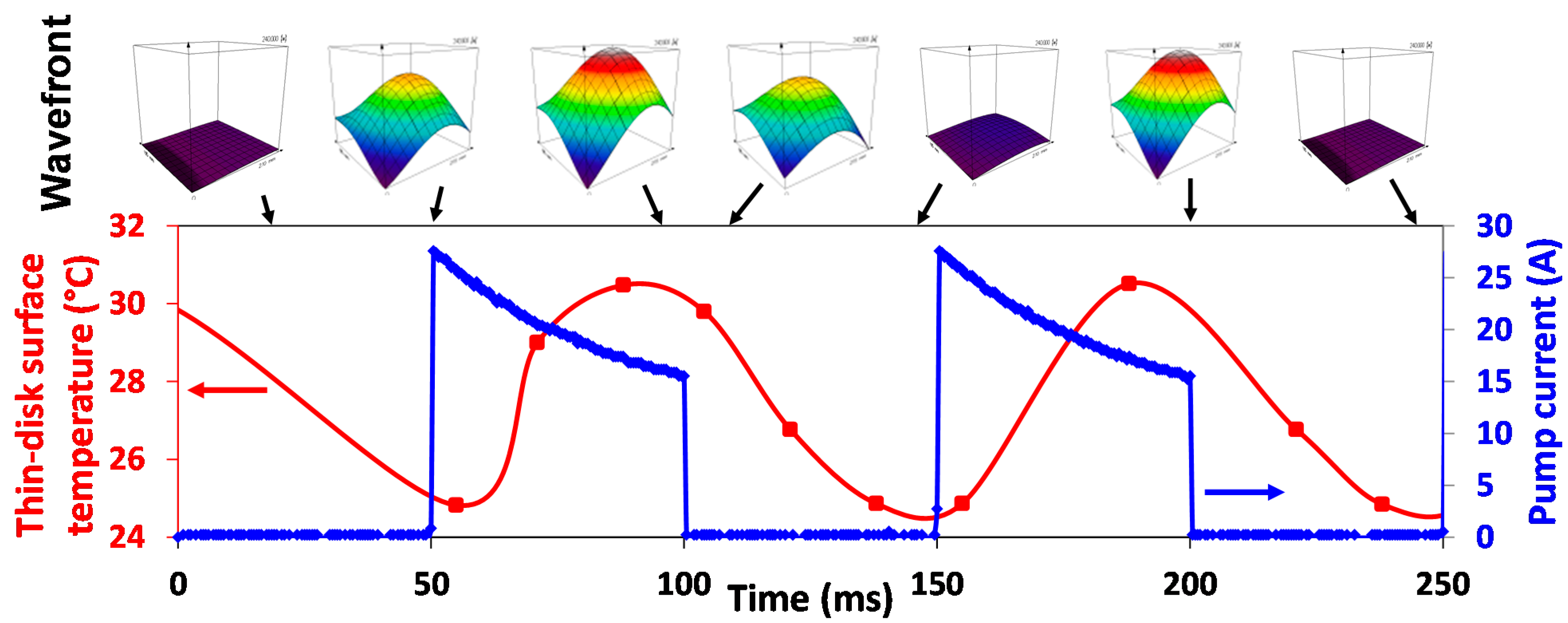
5.2. In Situ Thin Disk Deformation Measurements

The high pulse energy generated by the thin disk lasers necessitates a large mode size on the disk in order to avoid optical damage. However, the large mode area is more sensitive to optical phase distortions (OPD) caused mainly by the thin disk deformations at high pump intensities. The OPD limits the achievable pulse energy and beam quality. Further, the spherical part of the OPD, related to defocusing, affects the stability zones of the resonator of the regenerative amplifier. Thus, the knowledge of the thin disk deformations is essential for the design of a stable resonator for single-mode operation (TEM00 transverse mode) within the range of thin disk radii of curvature (ROC) for the used range of pump intensities. The aspherical part of the OPD increases the mode mismatching and higher mode content.
We have developed a compact setup for a precise measurement of the thin disk deformation based on a Hartmann–Shack wavefront sensor and a single-mode probe beam. It outperforms the interferometric methods in compactness, robustness, simplicity of alignment and resistance to mechanical vibrations. These properties allow one to use the setup in situ and to observe the thin disk deformation under the laser operation. Last, but not least, the aberration evaluation is a standard part of the wavefront sensor software. The measurement precision is in the range of a few nanometers, which is sufficient to observe the thin disk deformation caused by the pressure of the cooling water [34].
In the setup shown in Figure 14, the single-mode fiber-pigtailed laser diode emitting at the wavelength of 852 nm is collimated and magnified by a telescope to cover the whole thin disk surface. The originally flat wavefront is modulated at the thin disk surface and imaged by the telescope to the wavefront sensor. The high quality reference flat or curved mirror is used to verify the wavefront flatness or to calibrate the thin disk radius of curvature measurement, respectively. The thermal camera is added to the system to study the relationship between the thin disk temperature and its deformations.
Figure 14. In situ thin disk deformation measurement setup. The setup is shown without the laser cavity, which can be added. LD, laser diodes; L, lens; λ/4, quarter-wave plate; BS, beam splitter; PBS, polarizing beam splitter; SPF, short pass filter; PCTRL, polarization controller [36].
Applsci 05 00637 g014
We measured the ROC of a 220 µm-thick Yb:YAG thin disk soldered on a CuW heat sink. The measurement was done in a non-lasing condition initially. The thin disk ROC increased from the initial 4 m without pumping by 120 mm for a 2.7-mm pump spot diameter and by 340 mm for a 5.8-mm pump spot size at the pump intensity of 1.5 kW/cm2 in both cases [35]. The thin disk tends to be flatter when the pump is increased. Moreover, at the same pump intensity, the ROC change is more significant for larger pump spot sizes, because of the larger amount of heat induced in the thin disk. This is especially important for scaling up the output power by the pump spot size enlargement [34,35,36].
The in situ wavefront deformation measurement setup was used to evaluate deformations under the conventional broadband pumping at 940 nm and the zero-phonon line pumping at 969 nm. The highest deformations are at 940-nm pumping in the non-lasing condition and are reduced in the lasing condition. We found a nonlinear temperature rise and a large aspheric deformation for the 940-nm pumping. The different temperatures for lasing and non-lasing conditions makes the resonator alignment more complicated, and if the lasing is lost, e.g., by resonator misalignment, the temperature can rise above the thermal thin disk damage threshold, which is about 200 °C. Further, the deformations are reduced for 969-nm pumping. In the case of 969-nm pumping, the temperature rise is linear, and the aspheric deformation is weak. Interestingly, the temperature difference between the lasing and non-lasing regimes is small, which simplifies the resonator alignment and is less susceptible to the damage caused by lasing failure [31].
The latest development of our setup incorporates the time-resolved deformation measurement of the thin disk under pulsed pumping of a 50% duty cycle. The temporal resolution is based on triggering the Hartmann–Shack sensor or applying a pulsed probe beam of a 100-µs duration. The thin disk behavior has been studied for the pulsed pumping repetition rates between 1 and 100 Hz. For all of the repetition rates, we observed the highest thin disk temperature at the end of the pump pulse when also the thin disk deformation was maximal. The disk then relaxed close to the initial shape as the temperature decreased. The time evolution of the wavefront deformation was repeatable, and it occurred together with the pump pulses periodically (Figure 15). The comparison of the spherical aberration and defocus showed that the spherical aberration arises much faster than the defocus part and also decays faster [36]. Such behavior could explain the induced instabilities of laser mode operation that we observed previously [33].
Figure 15. Time-resolved measurement of the wavefront related to the thin disk deformation and temperature at a 10-Hz repetition rate and a 50-ms pump pulse duration [36].
Applsci 05 00637 g015

5.3. Single-Shot M2 Measurement

The M2 parameter helps to assess the laser beam quality. The most common principle of the M2 measurement is to scan the beam profile discretely along the propagation direction. A measurement time of several minutes is often required, which is not suitable for the pulsed lasers. Several single-shot techniques have been proposed to measure the M2 using diffraction gratings [52] and a wavefront sensor [53], but were shown to be more complex and to yield inaccurate results for multimode beams. Another approach to measure the M2 observes Rayleigh scattering of the beam in a gas or liquid-filled cell, but it is quite difficult to adjust the scattering medium [54]. Moreover, the image of the laser light scattered in the cell contains many speckle patterns, degrading the accuracy of the M2 measurement.
We have developed a single-shot M2 measurement based on a photosensitive glass (Figure 16a). The measurement system consists of the photosensitive glass plate and the imaging camera with a macro lens. When the laser beam is focused into the cross-sectional direction of the photosensitive glass plate, the visible fluorescence of the glass plate indicates the focusing property of the laser beam. Then, the visualized beam propagation in the glass is imaged precisely onto the camera to measure the beam diameters around the beam waist. Since the coherent laser beam is converted into incoherent fluorescence, the beam propagation image is free from speckle patterns. The M2 can be calculated from the single image within less than a second, though the beam widths at about thousand positions are evaluated. This simple technique allows the real-time monitoring of the beam quality. We obtained M2 = 1.1 from a fiber-coupled diode laser that is close to the actual value of M2 = 1.18 using the standard scanning method (Figure 16b) [55].
Figure 16. (a) Scheme of the experimental setup for the single-shot M2 measurement; (b) comparison of the beam caustic and M2 values from a commercial scanning M2 meter and the single-shot technique [55].
Applsci 05 00637 g016

6. Multi-Slab Laser Amplifier

The HiLASE Centre will operate a 100-J, 10-Hz, nanosecond cryogenically-cooled multi-slab laser. The laser is diode pumped and based on the Yb:YAG active medium. The laser is being developed in the collaboration with the Central Laser Facility, Rutherford Appleton Laboratory (U.K.). The fiber seed with an arbitrary pulse shaping is followed by a regenerative amplifier and multi-pass amplifier delivering up to 150-mJ pulses. Both of the front-end amplifiers are operated at room temperature. The pulse energy is then boosted in 10-J and 100-J multi-pass amplifiers. These amplifiers are based on multi-slabs cooled by a flow of gaseous helium at 150 K [56].
The HiLASE team supports the multi-slab laser development by advanced numerical modelling and wavefront correction by adaptive optics.

6.1. Numerical Modelling of Laser Amplifiers

One of the issues investigated by the HiLASE team is the optimization of the parameters of laser amplifiers in order to enhance their performance and to suppress the deleterious effects, like parasitic amplified spontaneous emission (ASE) oscillations, thermal wavefront aberrations and thermal-stress-induced birefringence. Thermally-induced beam distortions can be suppressed by a proper design of the amplifier geometry, including the width of an unpumped gap between the active area and the ASE absorbing layer, as well as the thickness and absorption coefficient of the absorbing layer itself [21,57]. An advanced numerical code for the evaluation of energetics and thermo-optical performance has been developed to provide the capability to quantify these effects and to design and optimize the amplifier for high performance.
The energetics modeling of the amplifiers is provided by our in-house-developed numerical code [20]. The code works in discrete time steps. During each step, the energy delivered to the amplifier by the pump beam using its ray tracing through the amplifier head is evaluated. This evaluation takes into account the pump pulse temporal profile, as well as the spectrum of the pump radiation. The absorbed energy is evaluated according to the absorption probability given by the number of unexcited active ions and the wavelength-dependent absorption cross-section. Spontaneously-emitted randomly-polarized photons are then generated by the Monte Carlo method according to the excited active ions density and emission cross-section. Bunches of the spontaneously-emitted photons are then traced through the amplifier volume giving rise to ASE. All of the surfaces of the amplifier can be considered to be Fresnel reflecting, anti-reflection (AR) coated, absorbing or diffusive. Various geometries, including rods, disks and slabs, can be investigated, and also, the ASE absorbing clad used to suppress parasitic oscillations can be involved. Using this code, the excited ion density, gain and heat deposition can be calculated. In the case of the lasers being developed at HiLASE, particular attention has been paid to the Yb:YAG disk amplifiers and Yb:YAG ceramics slab amplifiers with the Cr:YAG ceramics cladding.
The heat deposition within the amplifier volume obtained from the energetics modeling is consequently used as the input parameter for the thermo-optical modeling, which quantifies the thermally-induced wavefront aberrations and thermal-stress-induced birefringence leading to the laser beam depolarization. The base calculation of the temperature and stress distribution is done by the three-dimensional finite-element method using COMSOL Multiphysics software. The lateral surfaces of the amplifiers can be considered to be cooled by direct thermal contacts with the heat sink or by forced or natural convection cooling by liquid or gas [21,58,59,60]. The non-isothermal flow of the cooling medium is calculated separately in a 3D or simplified 2D, depending on the geometry, model resulting in the spatially-resolved heat transfer coefficient, which is then used as a boundary condition for fully 3D thermal stress-strain calculation. The temperature, mechanical stress and amplifier deformation are subsequently used for the calculation of the refractive indices’ changes, which result in wavefront aberrations. Jones calculus is used for the calculation of the beam depolarization induced by the thermal-stress birefringence.
The typical results of the energetics and thermo-optical calculations are shown in Figure 17 and Figure 18. These results were obtained for a square-shaped slab with dimensions of a 45 × 45 mm2 Yb:YAG active area surrounded by a 20 mm-thick Cr:YAG absorber layer. The slab was pumped by 1-ms pulses with an intensity of 5 kW·cm−2. The slab was placed in the eight-slab amplifier head, and the cooling was provided by forced-flow gaseous helium cooled down to 160 K. The velocity of the helium in the channels between two neighboring slabs was up to 30 m·s−1. The typical value of the heat transfer coefficient from the gas to the slab surface was evaluated as 1600 W·m−2·K−1. The heat load and temperature distributions calculated from the energetic calculations are shown in Figure 17. Note that the temperature distribution is no longer left-right symmetrical, because the cooling provided by the helium flow is from left to right.
Figure 17. Calculated (a) heat load and (b) temperature on the central cut plane. The squares marked by the black line show the border between Yb:YAG and Cr:YAG and the pumped and unpumped regions.
Applsci 05 00637 g017
The wavefront deformation expressed by the optical path difference (OPD) and the laser beam depolarization, which quantifies the ratio of the laser power transferred from x-oriented linear polarization to the perpendicular polarization direction, are shown in Figure 18.
Figure 18. Calculations of the (a) optical path difference and (b) depolarization of a multi-pass multi-slab amplifier.
Applsci 05 00637 g018
It should be noted that OPD and depolarization have been evaluated after 64 passes (four passes through two amplifier heads, eight slabs each). This represents the worst case, and the resulting OPD peak-to-valley (P-V) was found to be 8.65 waves at 1030 nm, while the average depolarization ratio was equal to 1.1%. The calculations show that the depolarization losses are relatively low, and the OPD could be compensated by a deformable mirror.
In the optimized case, the ratio between the active part and absorber was slightly changed. The best results were obtained for a size of Yb:YAG of 50 mm and of Cr:YAG of 17.5 mm. The overall size of the slab was kept unchanged. The OPD P-V dropped to 6.65 waves at 1030 nm. Because the beam is imaged between the amplifier heads, it is also rotated between them. If this rotation is considered during OPD calculations, the OPD further drops to 3.16 waves (Figure 19). Note that the residual depolarization is not affected by the optimization of the slab geometry or the beam rotation between amplifier heads and remains close to 1%.
Figure 19. Calculations of optical path difference for (a) the case with the optimized ratio of the active part and absorber part and (b) for the same case where the beam is rotated between amplifier heads.
Applsci 05 00637 g019
The total OPD that includes beam rotation between amplifiers, aberrations from optical elements, including the Seidel aberrations and manufacturing defects, the output beam shape and wavefront correction can be found in [61].

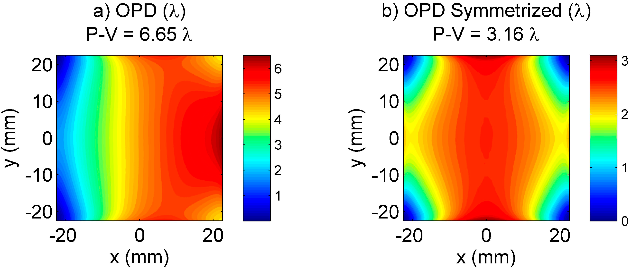
6.2. Wavefront Correction by a Deformable Mirror

The adaptive optics system for the 10-J cryogenically-cooled multi-slab amplifier was designed starting from the thermo-optical simulations. First, the amplifier head was studied and crucial parameters were estimated by two numerical models, including the aberration induced by thermal loading of the gain media [20,21]. In order to estimate the aberration of the output laser beam, another main source of aberrations was estimated by a different numerical model. The static aberration of optical components was modelled using Miró software and adding to each optical surface the optical aberration typical for the given component and scaled to fit the optics specifications [61]. Thermal aberrations were also included in the simulation. As a result, a sample wavefront profile was acquired (Figure 20a), which was then subject to numerical wavefront correction using another code. The simulation focused on the estimation of the number of actuators in order to provide sufficient wavefront correction. The results presented in Figure 20b clearly show that the target wavefront quality of RMS < 74 nm (set by the Maréchal criterion, i.e., RMS < 1/14 λ) is achieved by using actuator arrays with 6 × 6 actuators or more.
Figure 20. (a) Result of numerical estimation of the output laser beam wavefront; (b) result of wavefront correction simulation using uniform square arrays with various numbers of actuators; the sample wavefront to correct is case (a).
Applsci 05 00637 g020
An experimental setup was also developed in order to benchmark the numerical simulations [62]. The optical aberrations of the multi-slab amplifier head were simulated in the experiment. The heat-absorbing glass, which was used instead of the laser crystal, was heated by infrared laser diodes and generated the optical aberrations. By using a photo-controlled deformable mirror, irradiated by a mini-projector, various actuator arrays were simulated experimentally. Sufficient correction was achieved with the arrays having 5 × 5 actuators or more [62]. Further, the optimum parameters of a deformable mirror for the HiLASE 10-J multi-slab laser were determined. Since the photo-controlled deformable mirror prototype is not yet suitable for use in the high average power lasers, a bimorph deformable mirror with an array of 36 actuators was developed by Adaptica (Italy). Recently, the mirror has been implemented in the real laser amplifier at the Central Laser Facility, Rutherford Appleton Laboratory (U.K.). The feedback for its closed loop operation was provided by the SID4 wavefront sensor from Phasics (France). The results show good performance of the adaptive optics system, especially in terms of the focal spot improvement, delivering more than a 10× increase in the peak intensity [63].

7. Conclusions

The development of kilowatt-level lasers at the HiLASE Centre was introduced. The high average power beams are based on diode-pumped solid state laser technology. The thin-disk amplifiers are key parts of the 1-kHz and 100-kHz picosecond beamlines. The 1-kHz beamline was operated at 50 W of average power. The ring cavity for a 500-W amplifier is under development. The 100-kHz beamline achieved about 100 W in pulses compressed to less than 2 ps. The continuous-wave power of more than 500 W of the ring amplifier promises to reach a comparable output for the pulsed regime soon. HiLASE will also operate the cryogenically-cooled 100-J, 10-Hz multi-slab laser, which is currently being developed at the Central Laser Facility, Rutherford Appleton Laboratory (U.K.). We have supported the development of the 10-J and 100-J amplifiers by advanced numerical calculations and wavefront correction by the deformable mirror.
The powerful amplifiers’ development is supported by several other activities. The more powerful fiber oscillator will increase the stability and reliability of the laser systems. The repetition rate-stabilized fiber oscillator is intended for applications where precise synchronization between the laser pulses and accelerated electron bunches is needed. The in situ measurement of the thin disk deformations helps to design a proper and stable resonator for a large area fundamental mode. It also helps with the understanding of the improved laser performance under pulsed pumping. The single-shot M2 measurement enables fast evaluation of the key beam parameter.
The developed high average power lasers will be used for scientific and industrial applications, such as laser-induced damage testing, laser shock peening, laser processing and EUV generation, in the near future.

Acknowledgments

This work is co-financed by the European Regional Development Fund, the European Social Fund and the state budget of the Czech Republic (project HiLASE: CZ.1.05/2.1.00/01.0027; project DPSSLasers: CZ.1.07/2.3.00/20.0143; project Postdok: CZ.1.07/2.3.00/30.0057). This work is also supported by the Czech Science Foundation under project GA14-01660S.

Conflicts of Interest

The authors declare no conflict of interest.

References

  1. Strickland, D.; Mourou, G. Compression of amplified chirped optical pulses. Opt. Commun. 1985, 56, 219–221. [Google Scholar] [CrossRef]
  2. Koechner, W. Solid-State Laser Engineering; Springer-Verlag: New York, NY, USA, 2006; Volume 1, p. 750. [Google Scholar]
  3. Aggarwal, R.; Ripin, D.; Ochoa, J.; Fan, T. Measurement of thermo-optic properties of Y3Al5O12, Lu3Al5O12, YAIO3, LiYF4, LiLuF4, BaY2F8, KGd(WO4)2, and KY(WO4)2 laser crystals in the 80–300 K temperature range. J. Appl. Phys. 2005, 98, 103514. [Google Scholar] [CrossRef]
  4. Fan, T.; Ripin, D.; Aggarwal, R.; Ochoa, J.; Chann, B.; Tilleman, M.; Spitzberg, J. Cryogenic Yb3+-doped solid-state lasers. IEEE J. Sel. Top. Quantum Electron. 2007, 13, 448–459. [Google Scholar] [CrossRef]
  5. Rand, D.; Miller, D.; Ripin, D.; Fan, T. Cryogenic Yb3+-doped materials for pulsed solid-state laser applications. Opt. Mater. Express 2011, 1, 434–450. [Google Scholar] [CrossRef]
  6. Körner, J.; Jambunathan, V.; Hein, J.; Seifert, R.; Loeser, M.; Siebold, M.; Schramm, U.; Sikocinski, P.; Lucianetti, A.; Mocek, T.; et al. Spectroscopic characterization of Yb3+-doped laser materials at cryogenic temperatures. Appl. Phys. B 2014, 116, 75–81. [Google Scholar] [CrossRef]
  7. Jambunathan, V.; Koerner, J.; Sikocinski, P.; Divoky, M.; Sawicka, M.; Lucianetti, A.; Hein, J.; Mocek, T. Spectroscopic characterization of various Yb3+ doped laser materials at cryogenic temperatures for the development of high energy class diode pumped solid state lasers. In Proceedings of the SPIE, Prague, Czech Republic, 15–17 April 2013; Volume 8780, pp. 87800G-1–87800G-9.
  8. Eidam, T.; Hanf, S.; Seise, E.; Andersen, T.; Gabler, T.; Wirth, C.; Schreiber, T.; Limpert, J.; Tunnermann, A. Femtosecond fiber CPA system emitting 830 W average output power. Opt. Lett. 2010, 35, 94–96. [Google Scholar] [CrossRef] [PubMed]
  9. Giesen, A.; Hugel, H.; Voss, A.; Wittig, K.; Brauch, U.; Opower, H. Scalable concept for diode-pumped high-power solid-state lasers. Appl. Phys. B 1994, 58, 365–372. [Google Scholar] [CrossRef]
  10. Du, K.; Loosen, P.; Poprawe, R. Optical amplifier arrangement for a solid state laser. U.S. Patent 6,654,163 B1, 25 November 2003. [Google Scholar]
  11. Russbueldt, P.; Mans, T.; Rotarius, G.; Weitenberg, J.; Hoffmann, H.; Poprawe, R. 400 W Yb:YAG Innoslab fs-amplifier. Opt. Express 2009, 17, 12230–12245. [Google Scholar] [CrossRef] [PubMed]
  12. Hornung, M.; Keppler, S.; Bodefeld, R.; Kessler, A.; Liebetrau, H.; Korner, J.; Hellwing, M.; Schorcht, F.; Jackel, O.; Savert, A.; et al. High-intensity, high-contrast laser pulses generated from the fully diode-pumped Yb:glass laser system POLARIS. Opt. Lett. 2013, 38, 718–720. [Google Scholar] [CrossRef] [PubMed]
  13. Reagan, B.; Curtis, A.; Wernsing, K.; Furch, F.; Luther, B.; Rocca, J. Development of High Energy Diode-Pumped Thick-Disk Yb:YAG Chirped-Pulse-Amplification Lasers. IEEE J. Quantum Electron. 2012, 48, 827–835. [Google Scholar] [CrossRef]
  14. Reagan, B.; Wernsing, K.; Curtis, A.; Furch, F.; Luther, B.; Patel, D.; Menoni, C.; Rocca, J. Demonstration of a 100 Hz repetition rate gain-saturated diode-pumped table-top soft x-ray laser. Opt. Lett. 2012, 37, 3624–3626. [Google Scholar] [CrossRef] [PubMed]
  15. Goncalves-Novo, T.; Albach, D.; Vincent, B.; Arzakantsyan, M.; Chanteloup, J. 14 J/2 Hz Yb3+:YAG diode pumped solid state laser chain. Opt. Express 2013, 21, 855–866. [Google Scholar] [CrossRef] [PubMed]
  16. Wandt, C.; Klingebiel, S.; Keppler, S.; Hornung, M.; Loeser, M.; Siebold, M.; Skrobol, C.; Kessel, A.; Trushin, S.; Major, Z.; et al. Development of a Joule-class Yb:YAG amplifier and its implementation in a CPA system generating 1 TW pulses. Laser Photonics Rev. 2014, 8, 875–881. [Google Scholar] [CrossRef]
  17. Divoky, M.; Tokita, S.; Hwang, S.; Kawashima, T.; Kan, H.; Lucianetti, A.; Mocek, T.; Kawanaka, J. 1-J operation of monolithic composite ceramics with Yb:YAG thin layers: Multi-TRAM at 10-Hz repetition rate and prospects for 100-Hz operation. Opt. Lett. 2015, 40, 855–858. [Google Scholar] [CrossRef] [PubMed]
  18. Bayramian, A.; Aceves, S.; Anklam, T.; Baker, K.; Bliss, E.; Boley, C.; Bullington, A.; Caird, J.; Chen, D.; Deri, R.; et al. Compact, Efficient Laser Systems Required for Laser Inertial Fusion Energy. Fusion Sci. Technol. 2011, 60, 28–48. [Google Scholar] [CrossRef]
  19. Ertel, K.; Banerjee, S.; Mason, P.D.; Phillips, P.J.; Greenhalgh, R.J.S.; Hernandez-Gomez, C.; Collier, J.L. DiPOLE: A scalable laser architecture for pumping multi-Hz PW systems. In Proceedings of the SPIE, Prague, Czech Republic, 15–17 April 2013; Volume 8780, pp. 87801W-1–87801W-5.
  20. Sawicka, M.; Divoky, M.; Novak, J.; Lucianetti, A.; Rus, B.; Mocek, T. Modeling of amplified spontaneous emission, heat deposition, and energy extraction in cryogenically cooled multislab Yb3+:YAG laser amplifier for the HiLASE Project. J. Opt. Soc. Am. B 2012, 29, 1270–1276. [Google Scholar] [CrossRef]
  21. Slezak, O.; Lucianetti, A.; Divoky, M.; Sawicka, M.; Mocek, T. Optimization of Wavefront Distortions and Thermal-Stress Induced Birefringence in a Cryogenically-Cooled Multislab Laser Amplifier. IEEE J. Quantum Electron. 2013, 49, 960–966. [Google Scholar] [CrossRef]
  22. ELI-Extreme Light Infrastructure. Available online: http://www.eli-laser.eu (accessed on 31 July 2015).
  23. The HiPER Project. Available online: http://www.hiper-laser.org (accessed on 31 July 2015).
  24. Kuang, Z.; Perrie, W.; Edwardson, S.; Fearon, E.; Dearden, G. Ultrafast laser parallel microdrilling using multiple annular beams generated by a spatial light modulator. J. Phys. D 2014, 47, 115501. [Google Scholar] [CrossRef]
  25. Chyla, M.; Miura, T.; Smrz, M.; Severova, P.; Novak, O.; Endo, A.; Mocek, T. 50-mJ, 1-kHz Yb:YAG thin-disk regenerative amplifier with 969-nm pulsed pumping. In Proceedings of the SPIE, San Francisco, CA, USA, 2–4 February 2014; Volume 8959, pp. 89590S-1–89590S-6.
  26. Cummins, T.; Otsuka, T.; Yugami, N.; Jiang, W.; Endo, A.; Li, B.; O’Gorman, C.; Dunne, P.; Sokell, E.; O’Sullivan, G.; et al. Optimizing conversion efficiency and reducing ion energy in a laser-produced Gd plasma. Appl. Phys. Lett. 2012, 100, 061118. [Google Scholar] [CrossRef]
  27. Freitag, C.; Wiedenmann, M.; Negel, J.; Loescher, A.; Onuseit, V.; Weber, R.; Ahmed, M.; Graf, T. High-quality processing of CFRP with a 1.1-kW picosecond laser. Appl. Phys. A 2015, 119, 1237–1243. [Google Scholar] [CrossRef]
  28. Giesen, A.; Speiser, J. Fifteen years of work on thin-disk lasers: Results and scaling laws. IEEE J. Sel. Top. Quantum Electron. 2007, 13, 598–609. [Google Scholar] [CrossRef]
  29. Weichelt, B.; Voss, A.; Ahmed, M.; Graf, T. Enhanced performance of thin-disk lasers by pumping into the zero-phonon line. Opt. Lett. 2012, 37, 3045–3047. [Google Scholar] [CrossRef] [PubMed]
  30. Brown, D.; Cone, R.; Sun, Y.; Equall, R. Yb:YAG absorption at ambient and cryogenic temperatures. IEEE J. Sel. Top. Quantum Electron. 2005, 11, 604–612. [Google Scholar] [CrossRef]
  31. Smrz, M.; Miura, T.; Chyla, M.; Nagisetty, S.; Novak, O.; Endo, A.; Mocek, T. Suppression of nonlinear phonon relaxation in Yb:YAG thin disk via zero phonon line pumping. Opt. Lett. 2014, 39, 4919–4922. [Google Scholar] [CrossRef] [PubMed]
  32. Jambunathan, V.; Miura, T.; Tesnohlidkova, L.; Lucianetti, A.; Mocek, T. Efficient laser performance of a cryogenic Yb:YAG laser pumped by fiber coupled 940 and 969 nm laser diodes. Laser Phys. Lett. 2015, 12, 015002-1–015002-6. [Google Scholar] [CrossRef]
  33. Chyla, M.; Miura, T.; Smrz, M.; Jelinkova, H.; Endo, A.; Mocek, T. Optimization of beam quality and optical-to-optical efficiency of Yb:YAG thin-disk regenerative amplifier by pulsed pumping. Opt. Lett. 2014, 39, 1441–1444. [Google Scholar] [CrossRef] [PubMed]
  34. Miura, T.; Chyla, M.; Smrz, M.; Nagisetty, S.S.; Severova, P.; Novak, O.; Endo, A.; Mocek, T. In-situ optical phase distortion measurement of Yb:YAG thin disk in high average power regenerative amplifier. In Proceedings of the SPIE, San Francisco, CA, USA, 5–7 February 2013; Volume 8603, pp. 860303-1–860303-8.
  35. Muzik, J.; Chyla, M.; Nagisetty, S.S.; Miura, T.; Mann, K.; Endo, A.; Mocek, T. Precise curvature measurement of Yb:YAG thin disk. In Proceedings of the SPIE, Liberec, Czech Republic, 7–10 October 2014; Volume 9442, pp. 94420X-1–94420X-6.
  36. Chyla, M.; Nagisetty, S.S.; Severova, P.; Miura, T.; Mann, K.; Endo, A.; Mocek, T. Time-resolved deformation measurement of Yb:YAG thin disk using wavefront sensor. In Proceedings of the SPIE, San Francisco, CA, USA, 9–12 February 2015; Volume 9343, pp. 93431E-1–93431E-7.
  37. Larionov, M.; Neuhaus, J. Regenerative thin disk amplifier with a pulse energy of 120 mJ at 1 kHz. In Advanced Solid State Lasers; Optical Society of America: Shanghai, China, 2014; p. ATh2A.51. [Google Scholar]
  38. Yanovsky, V.; Felix, C.; Mourou, G. Why ring regenerative amplification (regen)? Appl. Phys. B 2002, 74, S181–S183. [Google Scholar] [CrossRef]
  39. Smrž, M.; Chyla, M.; Novák, O.; Miura, T.; Endo, A.; Mocek, T. Amplification of picosecond pulses to 100 W by an Yb:YAG thin-disk with CVBG compressor. In Proceedings of the SPIE, Prague, Czech Republic, 14–15 April 2015; Volume 9513, pp. 951304-1–951304-7.
  40. Painchaud, Y.; Paquet, C.; Guy, M. Optical Tunable Dispersion Compensators based on Thermally Tuned Fiber Bragg Gratings. Opt. Photonics News 2007, 18, 48–53. [Google Scholar] [CrossRef]
  41. Turčičová, H.; Novák, O.; Smrž, M.; Miura, T.; Endo, A.; Mocek, T. Picosesond pulses in deep ultraviolet produced by a 100 kHz solid-state thin disk laser. In Proceedings of the SPIE, Prague, Czech Republic, 14–15 April 2015; Volume 9513, pp. 95130V-1–95130V-6.
  42. Popmintchev, T.; Chen, M.; Popmintchev, D.; Arpin, P.; Brown, S.; Alisauskas, S.; Andriukaitis, G.; Balciunas, T.; Mucke, O.; Pugzlys, A.; et al. Bright Coherent Ultrahigh Harmonics in the keV X-ray Regime from Mid-Infrared Femtosecond Lasers. Science 2012, 336, 1287–1291. [Google Scholar] [CrossRef] [PubMed]
  43. Peralta, E.; Soong, K.; England, R.; Colby, E.; Wu, Z.; Montazeri, B.; McGuinness, C.; McNeur, J.; Leedle, K.; Walz, D.; et al. Demonstration of electron acceleration in a laser-driven dielectric microstructure. Nature 2013, 503, 91–94. [Google Scholar] [CrossRef] [PubMed]
  44. Healy, N.; Mailis, S.; Bulgakova, N.; Sazio, P.; Day, T.; Sparks, J.; Cheng, H.; Badding, J.; Peacock, A. Extreme electronic bandgap modification in laser-crystallized silicon optical fibres. Nat. Mater. 2014, 13, 1122–1127. [Google Scholar] [CrossRef] [PubMed]
  45. Novak, O.; Miura, T.; Smrz, M.; Huynh, J.; Severova, P.; Endo, A.; Mocek, T. Tunable mid-IR parametric conversion system pumped by a high-average-power picosecond Yb:YAG thin-disk laser. In Proceedings of the SPIE, Brussels, Belgium, 14–17 April 2014; Volume 9135, pp. 91350I-1–91350I-7.
  46. Novák, O.; Smrž, M.; Miura, T.; Turčičová, H.; Endo, A.; Mocek, T. Continuous-wave seeded mid-IR parametric system pumped by the high-average-power picosecond Yb:YAG thin-disk laser. In Proceedings of the SPIE, Prague, Czech Republic, 13–15 April 2015; Volume 9503, pp. 95030W-1–95030W-10.
  47. Chong, A.; Buckley, J.; Renninger, W.; Wise, F. All-normal-dispersion femtosecond fiber laser. Opt. Express 2006, 14, 10095–10100. [Google Scholar] [CrossRef] [PubMed]
  48. Měsíček, J.; Linnemann, J.; Smrž, M.; Miura, T.; Endo, A.; Mocek, T. Timing jitter measurement and stabilization of a mode-locked ytterbium fiber laser. In Proceedings of the SPIE, Prague, Czech Republic, 14–15 April 2015; Volume 9513, pp. 95130B-1–95130B-7.
  49. Jambunathan, V.; Horackova, L.; Miura, T.; Sulc, J.; Jelinkova, H.; Endo, A.; Lucianetti, A.; Mocek, T. Spectroscopic and lasing characteristics of Yb:YGAG ceramic at cryogenic temperatures. Opt. Mater. Express 2015, 5, 1289–1295. [Google Scholar] [CrossRef]
  50. Jambunathan, V.; Horackova, L.; Navratil, P.; Lucianetti, A.; Mocek, T. Narrow-band zero-phonon-line pumped efficient cryogenic Yb:YAG laser. In Proceedings of the CLEO/Europe 2015-European Conference on Lasers and Electro-Optics, Munich, Germany, 21–25 June 2015.
  51. Sulc, J.; Jelinkova, H.; Jambunathan, V.; Miura, T.; Endo, A.; Lucianetti, A.; Mocek, T. Wavelength tunability of laser based on Yb-doped YGAG ceramics. In Proceedings of the SPIE, San Francisco, CA, USA, 9–12 February 2015; Volume 9342, pp. 93421T-1–93421T-9.
  52. Cortes, R.; Villagomez, R.; Coello, V.; Lopez, R. Laser beam quality factor (M2) measured by distorted fresnel zone plates. Rev. Mex. Fis. 2008, 54, 279–283. [Google Scholar]
  53. Sheldakova, J.V.; Kudryashov, A.V.; Zavalova, V.Y.; Cherezova, T.Y. Beam quality measurements with Shack-Hartmann wavefront sensor and M2-sensor: Comparison of two methods. In Proceedings of the SPIE, San Jose, CA, USA, 22–24 June 2007; Volume 6452, pp. 645207-1–645207-5.
  54. Jorge, K.C.; Riva, R.; Silveira Rodrigues, N.A.; Destro, M.G. Real-time measurement of laser beam quality factor (M2) by imaging transverse scattered light. In Proceedings of the SPIE, San Jose, CA, USA, 22–24 June 2007; Volume 6452, pp. 645215-1–645215-10.
  55. Nagisetty, S.S.; Miura, T.; Smrz, M.; Kubecek, V.; Endo, A.; Mocek, T. Single shot M2 measurement for near infrared high energy laser pulses. In Proceedings of the SPIE, San Francisco, CA, USA, 9–12 February 2015; Volume 9343, pp. 93431F-1–93431F-8.
  56. Mason, P.D.; Banerjee, S.; Ertel, K.; Phillips, P.J.; Butcher, T.J.; Smith, J.M.; de Vido, M.; Tomlinson, S.; Chekhlov, O.; Shaikh, W.; et al. DiPOLE100: A 100 J, 10 Hz DPSSL using cryogenic gas cooled Yb:YAG multi slab amplifier technology. In Proceedings of the SPIE, Prague, Czech Republic, 14–15 April 2015; Volume 9513, pp. 951302-1–951302-9.
  57. Slezak, O.; Lucianetti, A.; Mocek, T. Efficient ASE Management in Disk Laser Amplifiers with Variable Absorbing Clads. IEEE J. Quantum Electron. 2014, 50, 1052–1060. [Google Scholar] [CrossRef]
  58. Slezak, O.; Yasuhara, R.; Lucianetti, A.; Mocek, T. Wavelength dependence of magneto-optic properties of terbium gallium garnet ceramics. Opt. Express 2015, 23, 13641–13647. [Google Scholar] [CrossRef] [PubMed]
  59. Divoky, M.; Smrz, M.; Chyla, M.; Sikocinski, P.; Severova, P.; Novak, O.; Huynh, J.; Nagisetty, S.S.; Miura, T.; Pilař, J.; et al. Overview of the HiLASE project: High average power pulsed DPSSL systems for research and industry. High Power Laser Sci. Eng. 2014, 2, e14 11–10. [Google Scholar] [CrossRef]
  60. Lucianetti, A.; Sawicka, M.; Slezak, O.; Divoky, M.; Pilar, J.; Jambunathan, V.; Bonora, S.; Antipenkov, R.; Mocek, T. Design of a kJ-class HiLASE laser as a driver for inertial fusion energy. High Power Laser Sci. Eng. 2014, 2, e13 11–10. [Google Scholar] [CrossRef]
  61. Divoky, M.; Sikocinski, P.; Pilar, J.; Lucianetti, A.; Sawicka, M.; Slezak, O.; Mocek, T. Design of high-energy-class cryogenically cooled Yb3+:YAG multislab laser system with low wavefront distortion. Opt. Eng. 2013, 52, 064201. [Google Scholar] [CrossRef]
  62. Pilar, J.; Slezak, O.; Sikocinski, P.; Divoky, M.; Sawicka, M.; Bonora, S.; Lucianetti, A.; Mocek, T.; Jelinkova, H. Design and optimization of an adaptive optics system for a high-average-power multi-slab laser (HiLASE). Appl. Opt. 2014, 53, 3255–3261. [Google Scholar] [CrossRef] [PubMed]
  63. Pilar, J.; Bonora, S.; Slezak, O.; Sawicka-Chyla, M.; Divoky, M.; Phillips, J.; Smith, J.; Ertel, K.; Collier, J.; Jelinkova, H.; et al. Adaptive optics system for HiLASE high average-power multi-slab laser system. In Proceedings of the Workshop on Adaptive Optics for Industry and Medicine, Padova, Italy, 15–19 June 2015; pp. 197–200.

