Article

High-Speed Visual Analysis of Fluid Flow and Heat Transfer in Oscillating Heat Pipes with Different Diameters

1
School of Hydraulic, Energy and Power Engineering, Yangzhou University, Yangzhou 225127, China
2
Key Laboratory of Energy Thermal Conversion and Control of Ministry of Education, School of Energy and Environment, Southeast University, Nanjing 210096, China
*
Author to whom correspondence should be addressed.
Appl. Sci. 2016, 6(11), 321; https://doi.org/10.3390/app6110321
Submission received: 1 September 2016 / Revised: 4 October 2016 / Accepted: 20 October 2016 / Published: 26 October 2016

Abstract

:
The oscillating heat pipe (OHP) is a new member in the family of heat pipes, and it has great potential applications in energy conservation. However, the fluid flow and heat transfer in the OHP as well as the fundamental effects of inner diameter on them have not been fully understood, which are essential to the design and optimization of the OHP in real applications. Therefore, by combining the high-speed visualization method and infrared thermal imaging technique, the fluid flow and thermal performance in the OHPs with inner diameters of 1, 2 and 3 mm are presented and analyzed. The results indicate that three fluid flow motions, including small oscillation, bulk oscillation and circulation, coexist or, respectively, exist alone with the increasing heating load under different inner diameters, with three flow patterns occurring in the OHPs, viz. bubbly flow, slug flow and annular flow. These fluid flow motions are closely correlated with the heat and mass transfer performance in the OHPs, which can be reflected by the characteristics of infrared thermal images of condensers. The decrease in the inner diameter increases the frictional flow resistance and capillary instability while restricting the nucleate boiling in OHPs, which leads to a smaller proportion of bubbly flow, a larger proportion of short slug flow, a poorer thermal performance, and easier dry-out of working fluid. In addition, when compared with the 2 mm OHP, the increasing role of gravity induces the thermosyphon effect and weakens the ‘bubble pumping’ action, which results in a little smaller and bigger thermal resistances of 3 mm OHP under small and bulk oscillation of working fluid, respectively.

Graphical Abstract

1. Introduction

With rapid increase in energy consumption, in order to realize the sustainable development of energy and environment, it is necessary to improve the efficiency of energy transfer, especially that of thermal energy transfer [1,2,3,4,5]. Note that, as one of several types of high efficiency heat transfer elements, the heat pipe has been widely used for improving the efficiency of thermal energy transfer and reducing the environmental impact during the heat exchanging process in real applications [6,7,8,9]. The oscillating heat pipe (OHP) is a new member in the family of heat pipes, which was proposed by Akachi [10,11] in 1990. Generally, OHP is fabricated by a sealed wickless capillary partially filled with the working fluid, which is arranged in an interconnected meandering manner. Compared with the conventional wick heat pipe, OHP has its own special operation mechanism due to its unique wickless structure [12]. In the OHP, owing to the sufficient small scale of the meandering capillary, working fluid can be distributed naturally into a series of vapor-liquid slugs by surface tension. When heated in one section (i.e., evaporator) and cooled in another (i.e., condenser), OHP establishes the temperature difference inside. As a result of this temperature difference and the uneven vapor-liquid distribution, a saturation pressure difference is established between the evaporator and condenser, coupled with non-uniform pressure oscillation produced in the OHP. These make the working fluids undergo complex oscillatory motions in the OHP, which achieves the heat transfer between the hot and cold sections. Both the special configuration and operation mechanism produce several additional advantages for the OHP in contrast to the conventional heat pipe [13,14]: simple construction and low cost, operational flexibility, capability for efficient heat transfer among multiple heat sources and sinks, etc. Therefore, the OHP possesses great application prospects in the areas of waste heat recovery [15,16], solar energy utilization [17,18], thermal management of hybrid vehicle [19,20], etc.
In this context, considerable efforts have been devoted to investigating the fluid flow and heat transfer in the OHP, so as to deeply understand its heat transfer mechanisms which are helpful for the design and optimization of the OHP in practical applications. Several theoretical models were proposed to investigate the oscillating motion and heat transfer of the vapor-liquid slugs in the OHP [21,22]. In addition, some researchers made efforts to enhance the thermal performance of the OHP by using the nanofluids [23,24] and mixed working fluid [25]. The optimal design of capillary channel geometry has also been conducted to successfully improve the operation stability and heat transfer of the flat-plate OHP [26,27,28]. Note that the previous studies indicated that the thermal performance of OHP is affected by many parameters such as geometric parameters, working fluid properties, heating load and heating modes, inclination angle, filling ratio, number of turns, and gravity load, etc. [29]. In particular, the inner geometry scale of the OHP must be small enough to form the necessary uneven distribution of vapor-liquid slugs inside, which is essential for successful operation of the OHP. Note that this uneven distribution of vapor-liquid slugs mainly depends on the ratio between the surface tension and gravity, as characterized by the Bond number:
B o = g ( ρ l ρ v ) σ D i ,
where Di is the inner diameter of the OHP, ρl and ρv are the corresponding densities of liquid and vapor, σ is the surface tension coefficient, and g is the gravity acceleration. Accordingly, several researchers [12,30] suggested the inner diameter of the OHP should be satisfied as
D i 2 σ ( ρ l ρ v ) g .
Meanwhile, it should be noted that the frictional flow resistance increases considerably with the decreasing inner diameter of the OHP, which impedes the normal oscillatory motions of working fluid in the OHP. Therefore, the optimal range of Di is suggested within the following range [31]:
0.7 σ ( ρ l ρ v ) g D i 1 . 8 σ ( ρ l ρ v ) g .
Thus, it can be concluded that the inner diameter has great influence on the fluid flow and heat transfer in the OHP, which has been further demonstrated by several available studies. Charoensawan et al. [32] experimentally investigated the thermal performance of the horizontal OHPs with Di = 1.0 and 2.0 mm, which indicated the better thermal performance of the OHP with bigger Di. In addition, via the comparison between the thermal resistance of two OHPs with different inner diameters, Yang et al. [33,34] found that the thermal performance of the OHP with Di = 1.0 mm was decreased by about 10% relative to that with Di = 2.0 mm. In addition, the shape of the cross section of the OHP also affects its thermal performance under the same hydraulic diameter. The effects of inner diameter on the thermal performance of OHP might be opposite for different working fluid, which is indicated by the experimental results by Rittidech et al. [35,36]. Particularly, based on an experimental test on the open-loop OHPs, Saha et al. [37] found that when compared with the OHP with Di = 0.9 mm, the OHP with Di = 1.5 mm demonstrated worse thermal performance, which is different from the conclusions by Charoensawan et al. [32] and Yang et al. [33,34].
In summary, although available research has demonstrated significant influence of the inner diameter on the thermal performance of the OHP, the real causes of this influence have not been fully revealed due to the limited insight into the fluid flow in the OHP during its operation. It is worth noting that several researchers (e.g., Tong et al. [38], Xu et al. [39], Khandekar et al. [40,41,42], and Borgmeyer et al. [43,44]) have proven that high-speed visualization of the operating OHP is an effective way for understanding the fluid flow in it. In addition, this previous research also pointed out that the detailed fluid flow behaviors inside are closely correlated with the thermal performance of the OHP, which are critical for clarifying the heat transfer mechanisms of the OHP. However, the available high-speed visualization experiments are mainly carried out on the OHPs with single inner diameters, with limited focus on the effects of inner diameter on the fluid flow. As a result (from the scenario described), the effects of inner diameters on the thermal performance of the OHP have not been deeply understood. Therefore, in this work, based on the high-speed visualization method and infrared thermal imaging technology, the vapor-liquid two-phase fluid flow in the OHPs with Di = 1.0, 2.0, 3.0 mm is investigated and compared to reveal the fundamental effects of the inner diameter. In addition, the motions of working fluid, distributions of vapor and liquid phases as well as the temperature distribution in the condenser are clarified and analyzed, in an effort to elucidate the relationship between the motions of working fluid and the heat transfer characteristics in the OHPs.

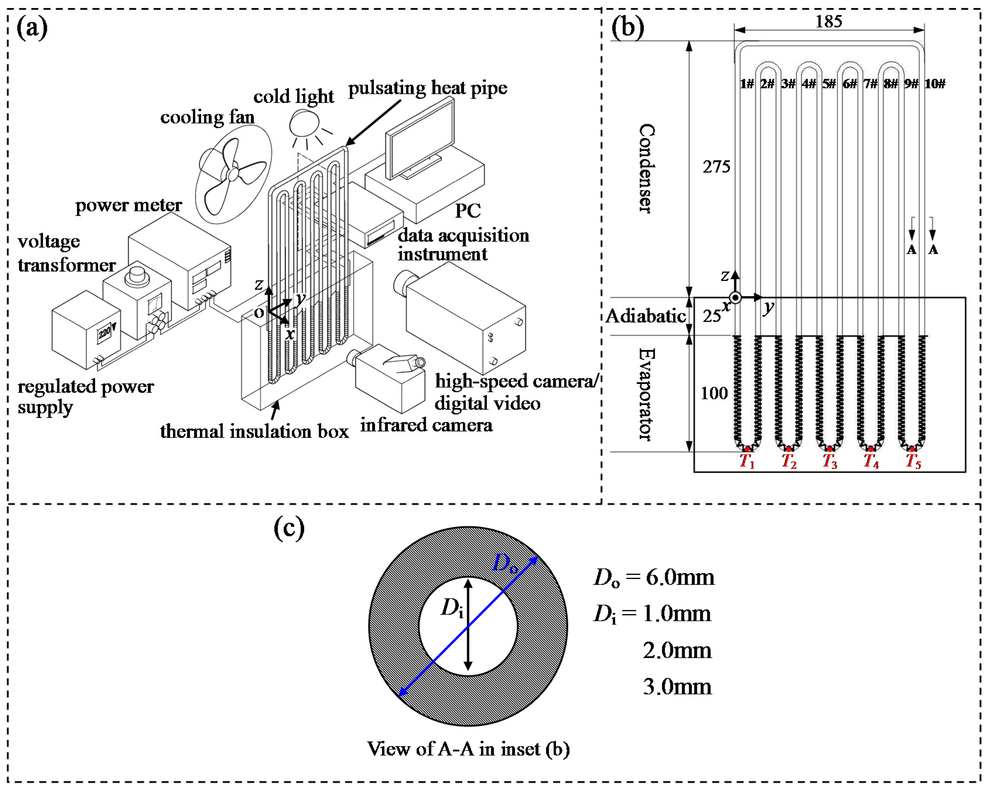
2. Experimental Setup

Figure 1 schematically illustrates the experimental setup utilized in the current study. As shown, the OHPs used here are fabricated by bending the pyrex glass capillaries into the interconnected meandering manner, forming 10 U-turns and parallel vertical tubes. The pyrex glass capillaries have external diameter of Do = 6.0 mm and inner diameters Di = 1.0, 2.0, 3.0 mm, respectively. As depicted in Figure 1b, the OHP with the dimensions of 400 mm × 185 mm is set vertically and heated at the bottom, which includes evaporator, adiabatic section and condenser with corresponding lengths of 100 mm, 25 mm and 275 mm. Before the experiment, the OHP is baked at 100 °C, evacuated to be 4.0 × 10⁻⁴ torr for 8 h by a vacuum pump, and then filled with methanol as the working fluid. The filling ratio is maintained at φ = 47% in this work. For the evaporator, the Ni-Cr wire with diameter of 0.25 mm is wrapped on the outer tube wall to supply the uniform heating load for the OHP. The whole evaporator and adiabatic section are embedded into the insulation box stuffed with the aluminum silicate insulation fibers, so as to ensure the relative error of heating load Q within 4.9%. The whole experiment is conducted in an environment with a constant temperature of 15 ± 0.5 °C, and thus the condenser of OHP can be cooled by the forced convection of the surrounding air via a cooling fan. By using an NEC TH9260 infrared camera (NEC Corporation, Tokyo, Japan) and the corresponding software, the infrared thermal images of the condenser during the operation of OHP are monitored, recorded and analyzed. The infrared camera possesses operation wavelength of 8–14 μm and noise equivalent temperature difference (NETD) of ±0.08 °C, as well as thermal image resolution of 640 × 480 pixels. The emissivity of the condenser surface is corrected before the experiment via comparing temperature signals measured by the infrared camera and the K-type thermal couple with a measuring error of ±0.1 °C. By checking the emissivity of condensation section, the deviation between the tested result of the condenser temperature and its real value via the infrared camera is less than 2.3 °C. The temperature of evaporator is measured by the thermocouples (diameter of 0.25 mm, OMEGA K-type with measuring error of ±0.1 °C, Omega Engineering, Santa Ana, CA, USA) fixed at the bottom of the evaporator, as marked in Figure 1b. The evaporator temperature are read and recorded by an Agilent 34970A data acquisition switch unit (Agilent Technologies, Santa Clara, CA, USA) with 6.5-digit accuracy, which has a maximum relative error of 0.5%.

3. Results and Discussions

3.1. Fluid Flow Motions inside OHP

As mentioned above, a deep insight into the vapor-liquid two-phase flow motions in the OHP during its quasi-steady operation is helpful for understanding the oscillating operation characteristics and heat transfer mechanisms of the OHP. In this work, after the start-up process [45], a quasi-steady station is achieved in the OHPs. Based on the summary of our visualization results under the quasi-steady operation of the OHPs, it can be seen from Figure 2 that the fluid flow inside the OHPs with three inner diameters under quasi-steady operation condition mainly exhibits three motions: small oscillation (S-O), bulk oscillation (B-O) and circulation (C). Since the evaporator and adiabatic section are embedded into the thermal insulation box in the current experiment, in order to show these three motions clearly, Figure 2b selects the corresponding fluid flow motions in either U-turn at the condenser of the OHP as the representative for analysis. As shown, when the small oscillation appears in the OHP, the vapor-liquid two-phase fluid only exhibits small, local oscillations in the tube, with limited mass exchange between the evaporator and condenser in each single vertical tube. Correspondingly, when the bulk oscillation occurs, the working fluid begins to oscillate with large amplitude in the OHP, resulting in bulk mass exchange between the evaporator and condenser and even among multiple U-turns. Differing from the oscillation motion, the circulation of working fluid is characterized by the circulation of working fluid in the whole OHP along the fixed direction. However, due to the non-uniformity driving pressure distributions in the OHP, the circulation speed of working fluid is changed.
In order to reflect the heat transfer performance of the OHP produced by these three motions, Figure 2c gives the typical infrared thermal images of the condenser under different motions. In addition, corresponding to the infrared thermal images in Figure 2c, Figure 3 further quantitatively represents the vertical temperature distribution in two adjacent tubes in a typical U-turn of the condenser under different quasi-steady operation states. In this figure, each curve is plotted by the average temperature data of every seven horizontal pixel points along each vertical tube in the typical U-turn. As indicated in Figure 2c and Figure 3a, under small oscillation motion, the heat transfer of the condenser mainly relied on its own heat conduction, except for the bottom regime, which is dependent on the sensible and latent heat transfer of the locally oscillating working fluid. Therefore, with the exception of high temperature at the bottom of the condenser, the temperature at the other part of the condenser nearly decreases linearly along the vertical direction to the top. As the bulk oscillation comes out, working fluid at the hot and cool ends of the OHP are able to exchange with each other, which obviously enhances the heat and mass transfer from the evaporator to the condenser. As a result, the area of high-temperature region at the bottom of the condenser is expanded, leading to an increase in the temperature level of the condenser (see Figure 2c and Figure 3b). Note that, under the bulk oscillation motion, due to the non-uniform heat and mass transfer strength caused by the uneven oscillation of working fluid among the OHP, every parallel tube at the condenser has different temperature distributions along the vertical direction. When the circulation of working fluid appears in the OHP, the adjacent parallel vertical tubes become ‘upheaders’ and ‘downcomers’ alternatively with corresponding hot and cold fluid flowing inside, resulting in alternatively high and low temperature on them (see Figure 3c).
Furthermore, the current experimental results also indicated that the three motions above coexist or, respectively, exist alone with increasing heating load under different inner diameters, with different coupling characteristics, as shown in Figure 4, where pt represents the percentage of duration for a certain fluid flow motion with respect to the total statistical duration. It can be seen that when Q is very small, the driving pressure inside the OHP is limited, which only triggers small oscillation of working fluids. With the increasing heating load, the driving pressure inside the OHP rises to overcome the flow resistance between the evaporator and condenser or even the adjacent U-turns, which induces the bulk oscillation of working fluid. At this time, the small and bulk oscillations appear intermittently in the OHP, and the duration of bulk oscillation is gradually increased when the heating load (i.e., the driving pressure in the OHP) further rises, as depicted in (i) and (ii) of Figure 4b. By further raising the heating load, the region of bulk oscillation is expanded to multiple U-turns, which eventually produces the circulation of working fluid (see (iii) of Figure 4b). Finally, the small oscillation and bulk oscillation of working fluid disappear sequentially under a large heating load, and the pure circulation of working fluid is achieved in the OHP (see Figure 4a and (iv) of Figure 4b). Note that, as shown by the comparison among the flow motions of working fluid in the OHPs with different inner diameters under the same heating load (see (ii), (v) and (vi) in Figure 4b), with respect to the OHP with Di = 2.0 mm, OHP with Di = 1.0 mm has larger frictional flow resistance inside, and thus the fluid flow motions under small driving pressure (e.g., small heating load) appears more easily (e.g., small oscillation in (ii), (v) and (vi) of Figure 4b). On the other hand, although the frictional flow resistance is lower in the OHP with Di = 3.0 mm, the resistance of capillary hysteresis is higher, and the vapor-liquid meniscus of vapor slugs is less rigid, which weakens the necessary ‘bubble pumping’ action [33,34] for the momentum transfer of working fluid inside the OHPs. Consequently, the percentage of oscillation motions is larger than that in the OHP with Di = 2.0 mm (e.g., small oscillation in (ii), (v) and (vi) of Figure 4b).

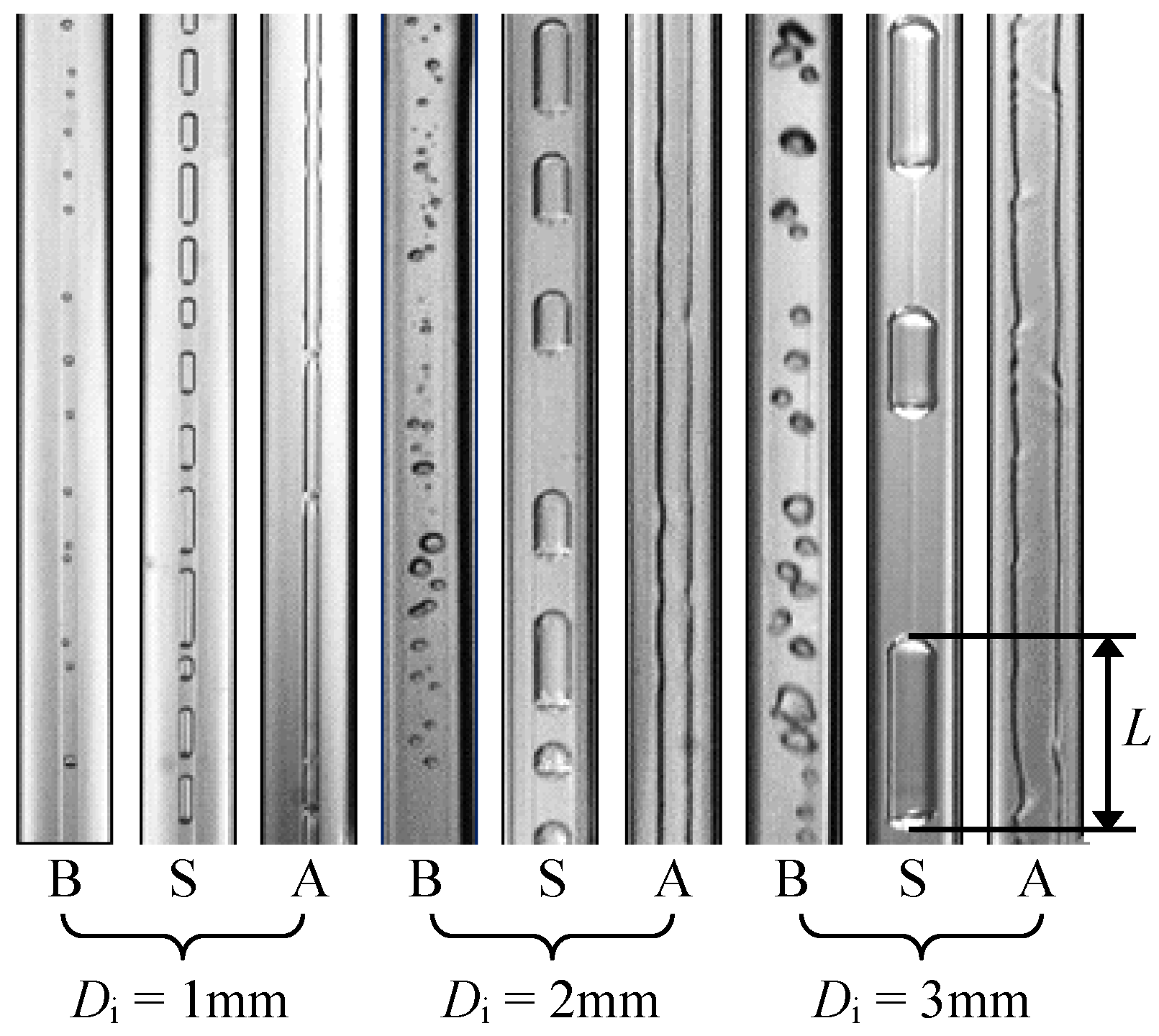
3.2. General Flow Patterns in OHP

As shown in Figure 5, Figure 6, Figure 7 and Figure 8, the above-mentioned complex fluid flows and phase changes also lead to the occurrences and evolutions of various flow patterns in the OHPs. Herein, three types of flow patterns, bubbly flow, slug flow and annular flow, are observed in the OHPs. Significantly, these flow patterns and their evolutions exhibit different characteristics under different inner diameters of the OHPs.

3.2.1. Bubbly Flow

As indexed by ‘B’ in Figure 5, bubbly flow is characterized by some dispersed bubbles flowing with the continuous liquid, with the length smaller than the inner diameter of the OHP. This flow pattern is mainly produced by the continuous nucleate boiling in the evaporator, which usually exists in the stream flowing from the evaporator to the condenser. Due to the small size and low volume fraction of the dispersed bubbles, the bubbly flow is easily condensed to pure liquid, and thus it barely appears in the downstream flowing from the condenser to the evaporator. Note that, when the fluid mixture undergoes fast turning and large disturbance, the bubbly flow may appear for a short time at the end of the long vapor slugs. Generally, bubbly flow is unstable in the OHPs due to the coalescence and shrinking of the dispersed bubbles. Via the comparison among the characteristics of bubbly flow in the OHPs with different inner diameters, it can be seen that the confined space in the OHP with Di = 1 mm restricts the nucleate boiling in the evaporator [46], resulting in the fewer dispersed bubbles in the bubbly flow than that under Di = 2 mm, 3 mm. In addition, the dispersed bubbles in the OHP with Di = 1 mm are hardly mixed due to the confinement, and always flow with the main stream in turn.

3.2.2. Slug Flow

When the slug flow appears in the OHPs, a series of vapor slugs with lengths bigger than the inner diameter flow with the main stream, as indexed by ‘S’ in Figure 5. This flow pattern is generally formed by the self-growth and coalescence of dispersed bubbles and the breakup of very long slugs. The slug flow almost emerges under all conditions under different inner diameters but is most common in the fluid mixture with oscillation and ‘downcomers’ under the fluid circulation in the OHPs. In addition, the length of slugs in the slug flow is usually changed because of the slugs’ growth, shrinking, coalescence and breakup. It is worth noting that as the mixing of dispersed bubbles is resisted in the small tube, the slug flow in the OHP with Di = 1 mm is mainly formed by the self-growth of dispersed bubbles and breakup of very long slugs rather than the coalescence of dispersed bubbles, which is different from that under the inner diameter of 2 mm and 3 mm.

3.2.3. Annular Flow

In the OHPs, when the continuous vapor flows through the center of the tubes with a liquid film formed around the inner tube wall, the annular flow comes out, as indexed by ‘A’ in Figure 5. This flow pattern is usually transformed from the slug flow, and usually appears in the ‘upheaders’ with a large volume fraction of vapor produced by the drastic boiling in the evaporator under high heating load. In the ‘upheaders’, the high-speed vapor induced by drastic boiling always breaks the liquid bridges between the vapor slugs and triggers the transition from slug flow to the annular flow. Moreover, as shown by Figure 5, smaller inner diameter induces greater effect of surface tension in the OHP and thus generates larger capillary instability, which leads to more irregular waves on the liquid film of the annular flow in the OHP with Di = 1 mm. These irregular waves easily cause the break of the continuous vapor core in the annular flow via the formation of the liquid bridges, which can induce the transition from the annular flow to the slug flow. Therefore, the stability of annular flow deteriorates with the decreasing inner diameter of the OHPs.

3.3. Flow Pattern Evolutions in Evaporator and Condenser

As discussed above, the general flow patterns in the OHPs with different diameters are closely related to the motions of vapor-liquid fluid mixture in the evaporator and condenser. Therefore, deeply analyzing the behaviors of vapor-liquid fluid mixture in the evaporator and condenser is beneficial for understanding the occurrences and evolutions of flow patterns in the OHPs.

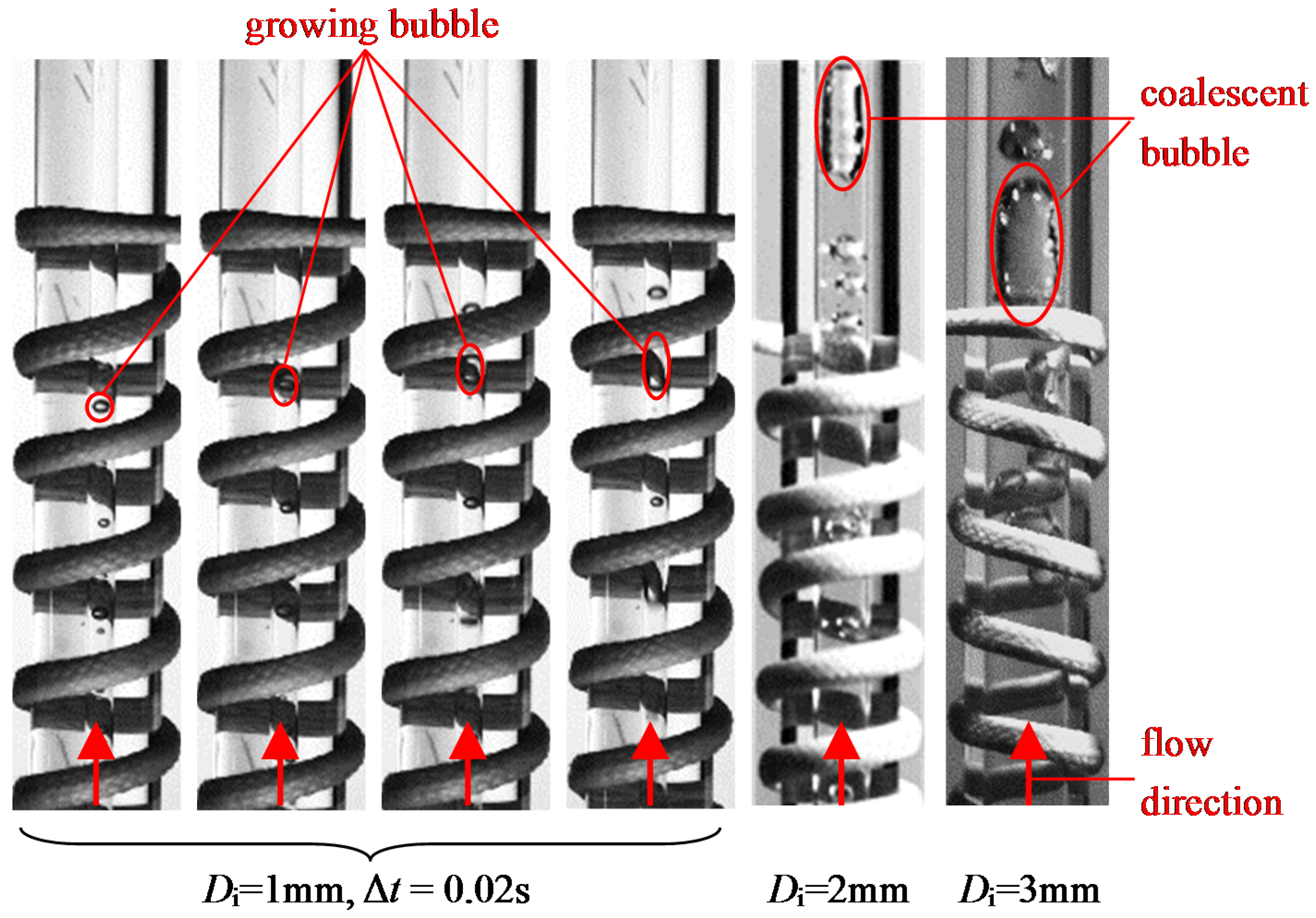
3.3.1. Flow Pattern Evolutions in Evaporator

In order to observe the flow patterns evolutions in the evaporator, the insulation box is opened in some experimental cases for visualization. As shown in Figure 6, when the working fluid in the evaporator is heated to reach the saturation state, nucleate boiling appears, and some dispersed small bubbles are produced, flowing up quickly due to the buoyancy and driving pressure difference between the hot and cold ends of the OHP. Meanwhile, the dispersed bubbles grow up or coalesce into the bigger ones and even the vapor slugs, which triggers the transition from bubbly flow to the slug flow. It can be clearly seen from the comparison among the flow pattern evolutions in the evaporators with different inner diameters that the transition from the bubbly flow to the slug flow is mainly dependent on the self-growth of the dispersed bubbles in the evaporator with Di = 1 mm, rather than the coalescence among them in the evaporators with diameter of 2 mm and 3 mm. Furthermore, less dispersed bubbles are produced by the nucleate boiling with the decreasing inner diameter, which further explains the characteristics of bubbly flow in the OHP with Di = 1 mm as discussed in the above section.

3.3.2. Flow Pattern Evolutions in the Condenser

As depicted in Figure 7, the visualization results indicate that the condensation of vapor in the condenser is the major cause of the breakup of continuous vapor core in the OHPs. It can be seen that, because of the continuous condensation of vapor, the vapor bonds emerge at several locations connecting the non-broken long vapor slug or the continuous vapor core of the annular flow (see long slugs A and B in Figure 7a and slug A′ in Figure 7b). As the condensation further proceeds, the long vapor slugs are broken up into several shorter ones via the breakup of vapor bonds, and the produced shorter ones continue shrinking (see slugs C and D produced by slug A as well as slugs E and F produced by slug B in Figure 7a, slug B′ and bubbles C′, D′ produced by slug A′ in Figure 7b). Based on the comparison among the breakup of long vapor slugs in the OHPs with different inner diameters, it is indicated that the reduction in the inner diameter of OHP results in the increasing role of surface tension, which enhances the capillary instability and thus induces more irregular fluctuation on the vapor-liquid interface. Therefore, as indicated in Figure 7a, there are more collapses on long slugs in the OHP with Di = 1 mm, forming more short slugs than that under Di = 2 mm, 3 mm.
Additionally, to further clarify the influence of inner diameter on the vapor-liquid two-phase distributions, Figure 8 compares the distribution of dimensionless bubble/slug length (L/Di) at the condensers of the OHPs with different Di under S-O and B-O motions of working fluid at Q = 90 W, where L is the real length of bubble/slug (see Figure 5). Herein, the percentage of bubble/slug length, Pi, is introduced to quantitatively represent the length distribution of bubbles/slugs
P j = n j n t × 100 % ,
where nj is the bubble/slug number within a certain range of dimensionless size, and nt is the total number of bubbles/slugs in a statistic duration of 10 s. As shown, the proportion of dispersed bubble (L/Di < 1) increases as the tube diameter increases, implying that the nucleate boiling at the evaporator with bigger inner diameter produces more dispersed bubbles flowing into the condenser and thus increases their proportion there. Compared with dispersed bubbles, as the inner diameter increases, the proportion of short slugs (1 ≤ L/Di < 10) experiences a decrease. As mentioned above, this is mainly attributed to the drop of capillary instability in the OHP, which reduces the probability of breakup from the long slugs to the shorter ones. Moreover, this decreasing capillary instability with increasing inner diameter also induces the larger proportion of long slugs (100 ≤ L/Di) under Di = 2 mm than that at Di = 1 mm. On the other hand, enlarging the inner diameter of the OHP also amplifies the absolute distance between vapor slugs, which decreases the probability of coalescences among vapor slugs into long vapor slugs, resulting in smaller proportion of long slugs (100 ≤ L/Di) under Di = 3 mm than that at Di = 2 mm.

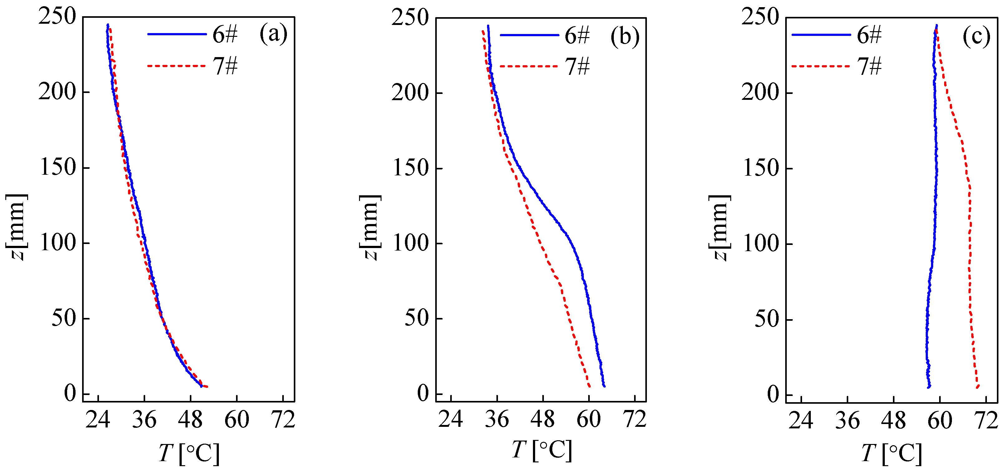
3.4. Thermal Performance

To clarify the correlations among heating load, fluid flow motions and thermal performance of the OHPs and further reveal the corresponding fundamental effects of inner diameter, the variation in the overall thermal resistance R versus heating load under different inner diameters is presented in Figure 9, where R is defined as
R = ( T ¯ e T ¯ c ) / Q .
In Equation (5), T ¯ e is the average temperature of evaporator calculated as the mean temperature of T1~T5 as shown in Figure 1b, and T ¯ c is the average temperature of condenser computed by averaging the temperature values of all pixel points on the infrared thermal images of the condenser. In addition, in order to represent the effect of inner diameter on the thermal performance of the OHP, the dimensionless inner diameter of the OHP, Di*, is defined as
D i * = D i σ / g Δ ρ = D i σ / g ( ρ l ρ v ) ,
where Di is the inner diameter of the OHP, g is the gravity acceleration, and Δρ and σ are the difference of density between liquid and vapor and surface tension coefficient at (Te-r + Tc-r)/2, respectively. Herein, Te-r and Tc-r are the reference temperatures of the evaporator and condenser, which are correspondingly defined as the highest operating temperature of the evaporator Te-r = 123.8 °C and ambient temperature of the condenser Tc-r = 15 °C. Actually, Di* is another expression form of the Bond number, which can characterize the ratio between the surface tension and gravity. As indicated in Figure 9, under the small oscillation of working fluid, the heat exchanged between the hot and cold ends of the OHP mainly relies on the heat conduction of working fluid and tube body, resulting in a slight decrease of R with the increasing heating load. When the bulk oscillation of working fluid occurs, the heat and mass transfer in the OHPs are significantly improved, leading to the most apparent decrease in R versus the increasing heating load (e.g., the changing of R within Q = 60–120 W under Di* = 1.31 (Di = 2 mm) in Figure 9). After the appearance of working fluid circulation, the capabilities of heat and mass transfer in the OHPs are further enhanced to be a steady level due to a certain amount of filled working fluid, when the thermal resistance of the OHPs gradually drops to be a steady value (e.g., the changing of R within Q = 110–200 W under Di* = 1.31 (Di = 2 mm) in Figure 9). Note that the dry-out of working fluid will emerge in the evaporator, represented by the sudden growing-up of the thermal resistance (e.g., Q = 160 W under Di* = 0.65 (Di = 1 mm) and Q = 220 W under Di* = 1.99 (Di = 2 mm) in Figure 9).
Herein, from the comparison among the changes of the thermal resistance and fluid flow motions versus heating load under different inner diameters of the OHPs, it can be seen that only the oscillation motions of working fluid occur in the major heating loads range (Q ≤ 110 W) under Di* = 0.65 (Di = 1 mm), due to the large frictional flow resistance. Furthermore, even under the same mode of working fluid motions, the large frictional flow resistance under Di* = 0.65 (Di = 1 mm) also reduces the heat and mass transfer rate into the OHP. Therefore, the OHP with Di* = 0.65 (Di = 1 mm) has the highest thermal resistance relative to those under Di* = 1.31 (Di = 2 mm) and Di* = 1.99 (Di = 3 mm). In addition, owing to the hardest supplement of working fluid for the nucleate boiling in the evaporator under the least amount of filled working fluid, the dry-out of working fluid occurs most easily in the OHP with Di* = 0.65 (Di = 1 mm). Compared with the OHP with Di* = 1.31 (Di = 2 mm), the gravity plays a more important role in the OHP with Di* = 1.99 (Di = 3 mm), producing the thermosyphon effect under the small oscillation of working fluid which facilitates the backflow of working fluid into the evaporator and enhances the heat and mass transfer [34]. Accordingly, at the small heating load (Q ≤ 40 W), thermal resistance under Di* = 1.99 (Di = 3 mm) is a little smaller than that under Di* = 1.31 (Di = 2 mm). However, under the bulk oscillation depending on the momentum exchange of working fluid, the thermal resistance under Di* = 1.99 (Di = 3 mm) turns out to be slightly larger than that under Di* = 1.31 (Di = 2 mm) (50 W≤ Q ≤ 100 W). It must be attributed to the decrease of rigidity on the vapor-liquid meniscus of vapor slugs, which weakens the necessary ‘bubble pumping’ effect for the exchange of working fluid in the OHPs and reduces the efficiency of heat and mass transfer.

4. Conclusions

By combining the high-speed visualization method and infrared thermal imaging technology, the vapor-liquid two-phase fluid flow in the OHPs with different inner diameters are observed and presented. The motions of working fluid, distributions of vapor and liquid phases, as well as the temperature distribution in the condenser under different diameters, are compared and analyzed to elucidate the fundamental effects of the inner diameter on the fluid flow as well as heat and mass transfer in the OHPs. In addition, the relationship between the motions of working fluid and heat transfer characteristics in the OHPs is discussed and clarified. Accordingly, several conclusions are drawn as follows:
(1) The major fluid flow motions inside OHP under quasi-steady operation condition are small oscillation, bulk oscillation and circulation, which are closely correlated with the heat and mass transfer performance in the OHPs, which can be reflected by the characteristics of infrared thermal images of the condenser. These three fluid flow motions coexist or correspondingly exist alone with the increasing heating load under different inner diameters.
(2) The general flow patterns in OHP include bubbly flow, slug flow and annular flow. The occurrence and transition of the flow patterns are mainly dependent on the phase-change phenomena in the evaporator and condenser of the OHPs. In particular, nucleate boiling in the evaporator is restricted by decreasing the inner diameter of the OHP, which leads to the smallest proportion of bubbly flow in the 1 mm OHP with respect to the other two. In addition, the decrease in inner diameter of the OHP can enhance the effects of surface tension and thus enlarge capillary instability on the vapor-liquid interface, which produces more collapses on the vapor core and long vapor slugs, forming more short slugs in the OHP with Di = 1 mm than that under Di = 2 and 3 mm.
(3) Due to the increasing driving pressure difference in the OHPs with growing heating load, the major fluid flow motions are changed from small oscillation to bulk ones and finally reach the circulation, which triggers a decrease in the overall thermal resistance of the OHPs. Particularly, the occurrence of bulk oscillation of working fluid causes the most apparent decrease in the thermal resistance versus the increasing heating load, whereas the thermal resistance of the OHPs drops to become a steady value when the working fluid circulation appears. Owing to the large frictional flow resistance and small amount of filled working fluid under the small diameter, the OHP with an inner diameter of 1 mm possesses the largest thermal resistance and undergoes the dry-out of working fluid most easily. When compared with the 2 mm OHP, the increasing role of gravity with growing inner diameter induces the thermosyphon effect and weakens the ‘bubble pumping’ action, which results in a little smaller and bigger thermal resistances of 3 mm OHP under small and bulk oscillation of working fluid, respectively.

Acknowledgments

The authors gratefully acknowledge the support provided by the National Natural Science Foundation of China (51406175) and the Natural Science Foundation of Jiangsu Province (BK20140488).

Author Contributions

Chengbin Zhang provided the guidance and supervision. Xiangdong Liu implemented the main research, checked and discussed the results, and wrote the paper. Qing Sun and Liangyu Wu performed the experiment, collected the experimental data, and checked the paper. All authors read and approved the final manuscript.

Conflicts of Interest

The authors declare no conflict of interest.

References

  1. Gasia, J.; Miró, L.; de Gracia, A.; Barreneche, C.; Cabeza, L.F. Experimental evaluation of a paraffin as phase change material for thermal energy storage in laboratory equipment and in a shell-and-tube heat exchanger. Appl. Sci. 2016, 6, 112. [Google Scholar] [CrossRef]
  2. Bo, Z.; Zhao, Q.; Shuai, X.R.; Yan, J.H.; Cen, K.F. Numerical study on the pressure drop of fluid flow in rough microchannels via the lattice Boltzmann method. Int. J. Numer. Methods Heat Fluid Flow 2015, 25, 2022–2031. [Google Scholar] [CrossRef]
  3. Sun, D.K.; Zhu, M.F.; Wang, J.; Sun, B.D. Lattice Boltzmann modeling of bubble formation and dendritic growth in solidification of binary alloys. Int. J. Heat Mass Transf. 2016, 94, 474–487. [Google Scholar] [CrossRef]
  4. Tian, F.B.; Bharti, R.P.; Xu, Y.Q. Deforming-Spatial-Domain/Stabilized Space–Time (DSD/SST) method in computation of non-Newtonian fluid flow and heat transfer with moving boundaries. Comput. Mech. 2014, 53, 257–271. [Google Scholar] [CrossRef]
  5. Jeng, T.-M.; Tzeng, S.-C. Numerical simulation of laminar forced convection of pin-fin heat-sink array in a Channel by Using Porous Approach. Appl. Sci. 2015, 5, 1846–1868. [Google Scholar] [CrossRef]
  6. Zhao, J.; Huang, S.B.; Gong, L.; Huang, Z.Q. Numerical study and optimizing on micro square pin-fin heat sink for electronic cooling. Appl. Therm. Eng. 2016, 93, 1347–1359. [Google Scholar] [CrossRef]
  7. Zhao, J.T.; Rao, Z.H.; Liu, C.Z.; Li, Y.M. Experimental study of oscillating heat pipe and phase change materials coupled for thermal energy storage and thermal management. Int. J. Heat Mass Transf. 2016, 99, 252–260. [Google Scholar] [CrossRef]
  8. Huang, H.J.; Shen, S.C.; Shaw, H.J. Design and fabrication of a novel hybrid-structure heat pipe for a concentrator photovoltaic. Energies 2012, 5, 4340–4399. [Google Scholar] [CrossRef]
  9. Faghri, A. Review and advances in heat pipe science and technology. J. Heat Transf. 2012, 134, 123001. [Google Scholar] [CrossRef]
  10. Akachi, H. Structure of a Heat Pipe. U.S. Patent 4,921,041, 1 May 1990. [Google Scholar]
  11. Akachi, H.; Polasek, F.; Stulc, P. Pulsating heat pipes. In Proceedings of the 5th International Heat Pipe Symposium, Melbourne, Australia, 17–20 November 1996; pp. 208–217.
  12. Zhang, Y.W.; Faghri, A. Advances and unsolved issues in pulsating heat pipes. Heat Transf. Eng. 2008, 29, 20–44. [Google Scholar] [CrossRef]
  13. Liao, Q.; Jen, T.C.; Chen, Q.H.; Li, L.J.; Cui, W.Z. Heat transfer performance in 3d internally finned heat pipe. Int. J. Heat Mass Trans. 2007, 50, 1231–1237. [Google Scholar] [CrossRef]
  14. Li, C.; Peterson, G.P.; Wang, Y. Evaporation/boiling in thin capillary wicks (I)—Wick thickness effects. J. Heat Trans. 2006, 128, 1312–1319. [Google Scholar] [CrossRef]
  15. Rittidech, S.; Dangeton, W.; Soponronnarit, S. Closed-ended oscillating heat-pipe (CEOHP) air-preheater for energy thrift in a dryer. Appl. Energy 2005, 81, 198–208. [Google Scholar] [CrossRef]
  16. Meena, P.; Rittidech, S.; Poomsa-ad, N. Application of closed-loop oscillating heat-pipe with check valves (CLOHP/CV) air-preheater for reduced relative-humidity in drying systems. Appl. Energy 2007, 5, 553–564. [Google Scholar] [CrossRef]
  17. Rittidech, S.; Wannapakne, S. Experimental study of the performance of a solar collector by closed-end oscillating heat pipe (CEOHP). Appl. Therm. Eng. 2007, 27, 1978–1985. [Google Scholar] [CrossRef]
  18. Rittidech, S.; Donmaung, A.; Kumsombut, K. Experimental study of the performance of a circular tube solar collector with closed-loop oscillating heat-pipe with check valve (CLOHP/CV). Renew. Energy 2009, 34, 2234–2238. [Google Scholar] [CrossRef]
  19. Burban, G.; Ayel, V.; Alexandre, A.; Lagonotte, P.; Bertin, Y.; Romestant, C. Experimental investigation of a pulsating heat pipe for hybrid vehicle applications. Appl. Therm. Eng. 2013, 50, 94–103. [Google Scholar] [CrossRef]
  20. Jason, C.; Wang, X. Experimental investigation of pulsating heat pipe performance with regard to fuel cell cooling application. Appl. Therm. Eng. 2013, 50, 268–274. [Google Scholar]
  21. Shafii, M.B.; Faghri, A.; Zhang, Y.W. Analysis of heat transfer in unlooped and looped pulsating heat pipes. Int. J. Numer. Methods Heat Fluid Flow 2002, 12, 585–609. [Google Scholar] [CrossRef]
  22. Brian, H.; Faghri, A. Analysis of pulsating heat pipe with capillary wick and varying channel diameter. Int. J. Heat Mass. Trans. 2005, 48, 2635–2651. [Google Scholar]
  23. Ji, Y.L.; Ma, H.B.; Su, F.M.; Wang, G.Y. Particle size effect on heat transfer performance in an oscillating heat pipe. Exp. Therm. Fluid Sci. 2011, 35, 724–727. [Google Scholar] [CrossRef]
  24. Qu, J.; Wu, H.Y.; Cheng, P. Thermal performance of an oscillating heat pipe with Al2O3-water nanofluids. Int. Commun. Heat Mass Transf. 2010, 37, 111–115. [Google Scholar] [CrossRef]
  25. Kim, J.S.; Bui, N.H.; Jung, H.S.; Lee, W.H. The study on pressure oscillation and heat transfer characteristics of oscillating capillary tube heat pipe using mixed working fluid. J. Mech. Sci. Technol. 2003, 17, 1533–1542. [Google Scholar]
  26. Thompson, S.M.; Cheng, P.; Ma, H.B. An experimental investigation of a three-dimensional flat-plate oscillating heat pipe with staggered microchannels. Int. J. Heat Mass Trans. 2011, 54, 3951–3959. [Google Scholar] [CrossRef]
  27. Cheng, P.; Thompson, S.; Boswell, J.; Ma, H.B. An investigation of flat-plate oscillating heat pipes. J. Electron. Packag. 2010, 132, 041009. [Google Scholar] [CrossRef]
  28. Rhodes, M.J.; Taylor, M.R.; Monroe, J.G.; Thompson, S.M. Experimental investigation of a flat-plate oscillating heat pipe with modified evaporator and condenser. In Proceedings of the ASME 2014 International Mechanical Engineering Congress and Exposition, Montreal, QC, Canada, 14–20 November 2014. [CrossRef]
  29. Han, X.H.; Wang, X.H.; Zheng, H.C.; Chen, G.M. Review of the development of pulsating heat pipe for heat dissipation. Renew. Sustain. Energy Rev. 2016, 59, 692–709. [Google Scholar] [CrossRef]
  30. Groll, M.; Khandekar, S. Pulsating heat pipe: Progress and prospects. In Proceedings of the International Conference on Energy and the Environment, Shanghai, China, 22–24 May 2003; pp. 723–730.
  31. Dobson, R.T.; Harms, T.M. Lumped parameter analysis of closed and open oscillatory heat pipes. In Proceedings of the 11th International Heat Pipe Conference, Tokyo, Japan, 12–16 September 1999; pp. 137–142.
  32. Charoensawan, P.; Terdtoon, P. Thermal performance of horizontal closed-loop oscillating heat pipes. Appl. Therm. Eng. 2008, 28, 460–466. [Google Scholar] [CrossRef]
  33. Yang, H.H.; Khandekar, S.; Groll, M. Operational limit of closed loop pulsating heat pipes. Appl. Therm. Eng. 2008, 28, 49–59. [Google Scholar] [CrossRef]
  34. Yang, H.H.; Khandekar, S.; Groll, M. Performance characteristics of pulsating heat pipes as integral thermal spreaders. Int. J. Therm. Sci. 2009, 18, 815–824. [Google Scholar] [CrossRef]
  35. Rittidech, S.; Pipatpaiboon, N.; Terdtoon, P. Heat-transfer characteristics of a closed-loop oscillating heat-pipe with check valve. Appl. Energy 2007, 84, 565–577. [Google Scholar] [CrossRef]
  36. Rittidech, S.; Terdtoon, P.; Murakami, M.; Kamonpet, P.; Jompakdee, W. Correlation to predict heat transfer characteristics of a closed-end oscillating heat pipe at normal operating condition. Appl. Therm. Eng. 2003, 23, 497–510. [Google Scholar] [CrossRef]
  37. Saha, M.; Feroz, C.M.; Ahmed, F.; Mujib, T. Thermal performance of an open loop closed end pulsating heat pipe. Heat Mass Transf. 2012, 48, 259–265. [Google Scholar] [CrossRef]
  38. Tong, B.Y.; Wong, T.N.; Ooi, K.T. Closed-loop pulsating heat pipe. Appl. Therm. Eng. 2001, 21, 1845–1862. [Google Scholar] [CrossRef]
  39. Xu, J.L.; Zhang, X.M. Start-up and steady thermal oscillation of a pulsating heat pipe. Heat Transf. 2005, 41, 685–694. [Google Scholar] [CrossRef]
  40. Khandekar, S.; Charoensawan, P.; Groll, M.; Terdtoon, P. Closed loop pulsating heat pipes Part B: Visualization and semi-empirical modeling. Appl. Therm. Eng. 2003, 23, 2021–2033. [Google Scholar] [CrossRef]
  41. Khandekar, S.; Groll, M. An insight into thermo-hydrodynamic coupling in closed loop pulsating heat pipes. Int. J. Therm. Sci. 2004, 43, 13–20. [Google Scholar] [CrossRef]
  42. Khandekar, S.; Gautam, A.P.; Shama, P.K. Multiple quasi-steady states in a closed loop pulsating heat pipe. Int. J. Therm. Sci. 2009, 48, 535–546. [Google Scholar] [CrossRef]
  43. Borgmeyer, B.; Ma, H.B. Experimental investigation of oscillating motions in a flat plate pulsating heat pipe. J. Thermophys. Heat Transf. 2007, 21, 405–409. [Google Scholar] [CrossRef]
  44. Wilson, C.; Borgmeyer, B.; Winholtz, R.A.; Ma, H.B.; Jacobson, D.L.; Hussey, D.S.; Arif, M. Visual observation of oscillating heat pipes using neutron radiography. J. Thermophys. Heat Transf. 2008, 22, 366–372. [Google Scholar] [CrossRef]
  45. Liu, X.D.; Chen, Y.P.; Shi, M.H. Dynamic performance analysis on start-up of closed loop pulsating heat pipes (CLPHPs). Int. J. Therm. Sci. 2012, 65, 224–233. [Google Scholar] [CrossRef]
  46. Ghiu, C.D.; Joshi, Y.K. Visualization study of pool boiling from thin confined enhanced structures. Int. J. Heat Mass Trans. 2005, 48, 4287–4299. [Google Scholar] [CrossRef]
Figure 1. Experimental apparatus: (a) schematic of experimental setup; (b) schematic of experimental oscillating heat pipe; and (c) cross section geometry of A–A in inset (b).
Applsci 06 00321 g001
Figure 2. Fluid flow motions in the oscillating heat pipe (OHP) and corresponding experimental images as well as infrared thermal images of the condenser: (a) schematic of fluid flow motions; (b) snapshots of different fluid flow motions in a typical U-turn of condenser; and (c) infrared thermal images of the condenser.
Applsci 06 00321 g002
Figure 3. Vertical temperature distribution of condenser under different quasi-steady operation states corresponding to Figure 2c (6#-7# U-turn): (a) small oscillation (Q = 30 W); (b) big oscillation (Q = 70 W); and (c) circulation (Q = 140 W).
Applsci 06 00321 g003
Figure 4. Variation of fluid flow motions with increasing heating load: (a) schematic of change in fluid flow motions with increasing heating load; and (b) time series of fluid flow motions and their corresponding duration fractions under different heating loads and inner diameters. Fluid flow motions mode index: 0: S-O; 1: B-O; and 2: C.
Applsci 06 00321 g004
Figure 5. Flow patterns occurring in the OHPs with different diameters. Flow patterns indexes: B: bubbly flow; S: slug flow; A: annular flow.
Applsci 06 00321 g005
Figure 6. Evolution of flow pattern in the evaporators of the OHPs with different inner diameters (Q ~ 100 W).
Applsci 06 00321 g006
Figure 7. Evolution of flow pattern in the vertical tube at the condenser of the OHPs with different inner diameters: (a) snapshots of flow pattern evolution under Di = 1mm; (b) snapshots of flow pattern evolution under Di = 2mm; and (c) snapshots of flow pattern evolution under Di = 3mm.
Applsci 06 00321 g007
Figure 8. Distribution of bubbles/slugs length at the condenser in the OHPs with different inner diameters under quasi-steady S-O and B-O fluid motion: (a) Di = 1mm under Q = 90W; (b) Di = 2mm under Q = 90W; and (c) Di = 3mm under Q = 90W.
Applsci 06 00321 g008
Figure 9. Variation of thermal resistance and fluid flow motions versus increasing heating load under different inner diameters of the OHPs.
Applsci 06 00321 g009

