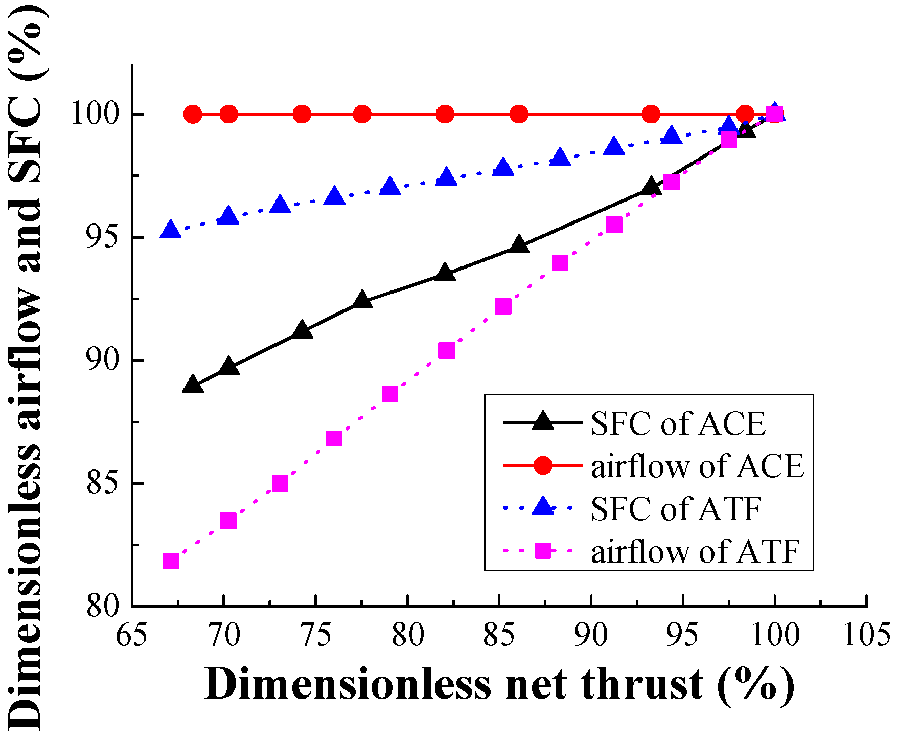
According to the public references so far, VCE can keep airflow constant during subsonic cruise throttling by modulating variable geometries as power reduces, which can decrease spillage drag and increase installed thrust efficiently. This is the most remarkable variable-cycle-characteristic of VCE. Benefiting from the additional third bypass, ACE has greater potential to flexibly modulate airflow and pressure ratio. Therefore, it is necessary to study the control schedule of variable geometries’ modulation based on the modeling study, which focuses on retaining airflow as thrust is reduced during the subsonic and supersonic cruise.
Due to the strong coupling among the variable geometries, variable geometry adjustment can affect the components which directly match. Therefore, the strong coupling of variable geometries is what makes the modulation study extremely challenging. Due to the unchanged inlet guide vanes of the front fan, the LPRS is kept constant to maintain airflow during subsonic and supersonic cruise throttling.
3.1. Variable Geometries Modulation during Supersonic Cruise
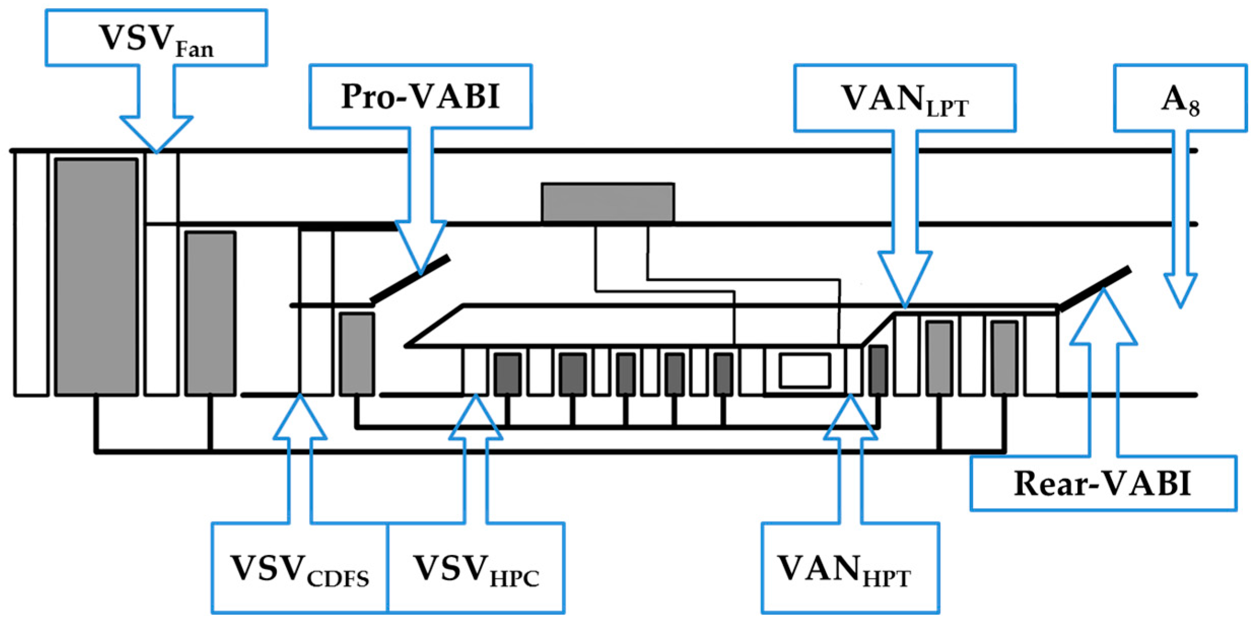
To assure remarkable performance, ACE operates in double bypass mode during supersonic cruise with a working condition is set as 11 km, 1.5 Ma. According to the quantitative research and components matching mechanisms, sensitivity analysis of six variable geometries (VSV
Fan, VSV
CDFS, VSV
HPC, Rear-VABI, VAN
LPT and A
8) modulation of the engine airflow and net thrust can be obtained. The VSV
Fan can change from 15 degrees (D) to −5 degrees. Meanwhile, the VSV
CDFS can vary from 45 degrees to 0 degrees. The VSV
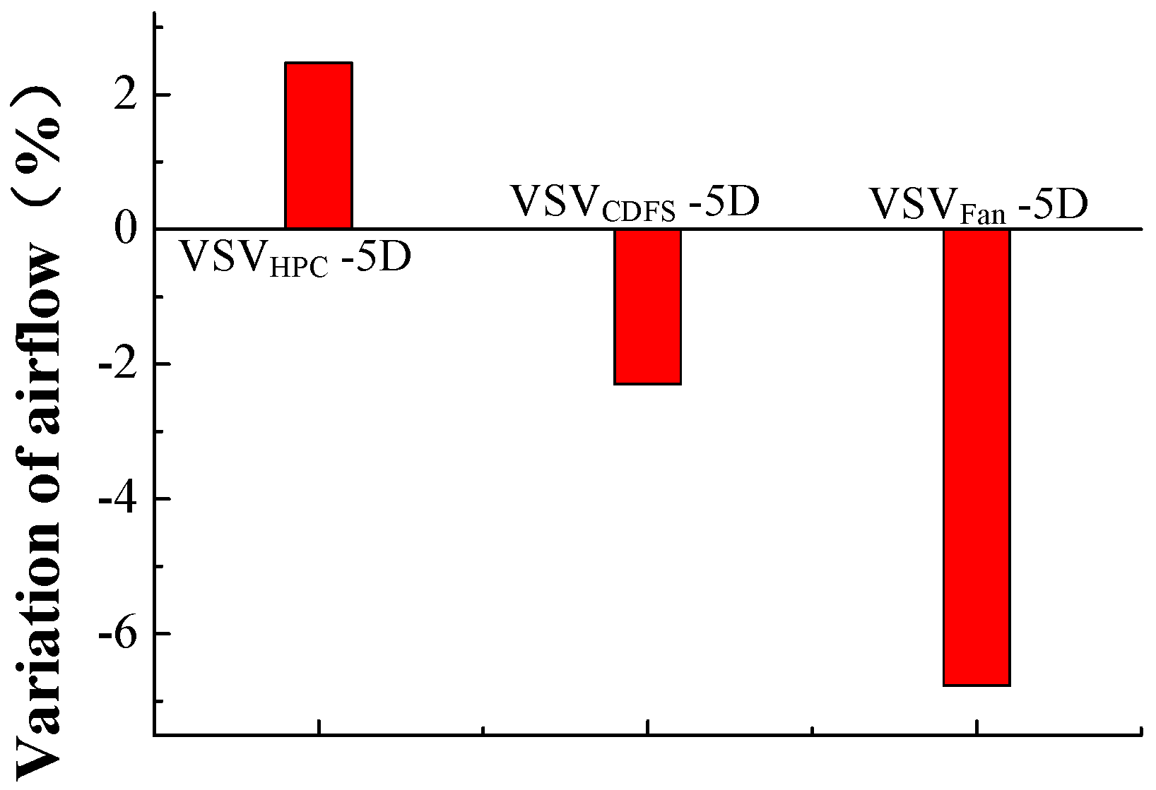
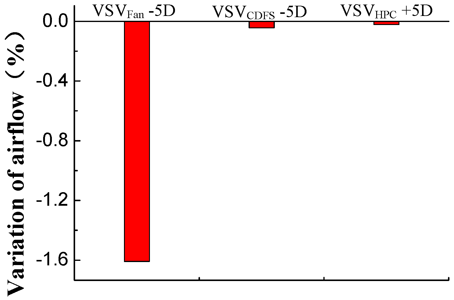
HPC can change from −10 degrees to 10 degrees. Consequently, the sensitivity analysis based on VSV changing −5 degrees. When the engine operates at double bypass mode and LPRS is constant as stated above, the reduction of variable fan flow capacity by turning down VSV
Fan can decrease the thrust due to lower HPT inlet temperature (T
t4). This reduction drives more air flowing into third bypass, increasing B
3, while decreasing low pressure compression work. Then, an increased trend of LPRS occurs because of the excess of LPT output work for less low pressure compression work. Hence, for a constant LPRS, less fuel should be injected. Further, T
t4 declines, leading to the reduced net thrust. Turning down VSV
Fan increases the outlet back pressure of the front fan. Then the front fan pressure ratio rises and the engine airflow decreases, as shown in
Figure 7 and
Figure 8.
The reduction of HPC flow capacity by turning down VSV
HPC can decrease the thrust due to lower T
t4. This reduction drives more air flow into the core bypass, increasing B
1 while decreasing engine core flow. Then, the required compression work of HPC is reduced and the distributing compression work of CDFS increases, which improves CDFS suction capacity and hence air flow. Thus, the outlet back pressure of variable fan decreases, which results in a reduction of the variable fan and front fan pressure ratio. Finally, the engine airflow increases, shown in
Figure 7 and
Figure 8. Meanwhile, the amount of low pressure compression work decreases. Then, an increased trend of LPRS occurs because of the excess of LPT output work for less low pressure compression work. Hence, for a constant LPRS, less fuel is injected and T
t4 is reduced. Finally, the specific thrust reduces, leading to the decrease of net thrust.
When the engine operates in double bypass mode and LPRS is maintained at a constant level, turning down VSV
CDFS decreases T
t4 and net thrust. Directly, turning down VSV
CDFS decreases CDFS flow capacity. CDFS compression work drops when other parameters remain constant during the decrease of CDFS flow capacity. Then, this drop increases high pressure rotation speed (HPRS) and hence HPC suction capacity. As a result, there is greater engine core flow driving LPT. In this way, LPRS tends to rise as LPT output work improves. Hence for a constant LPRS, fuel flow has to decrease, resulting in the decrease of T
t4. Therefore, net thrust decreases for lower T
t4. According to the flow continuity relationship, the front fan flow capacity drops for the decrease of CDFS flow capacity. As for the front fan, its working point moves up slightly along the referred speed line. As shown in
Figure 7 and
Figure 8, the corrected flow of front fan decreases as the engine airflow reduces.
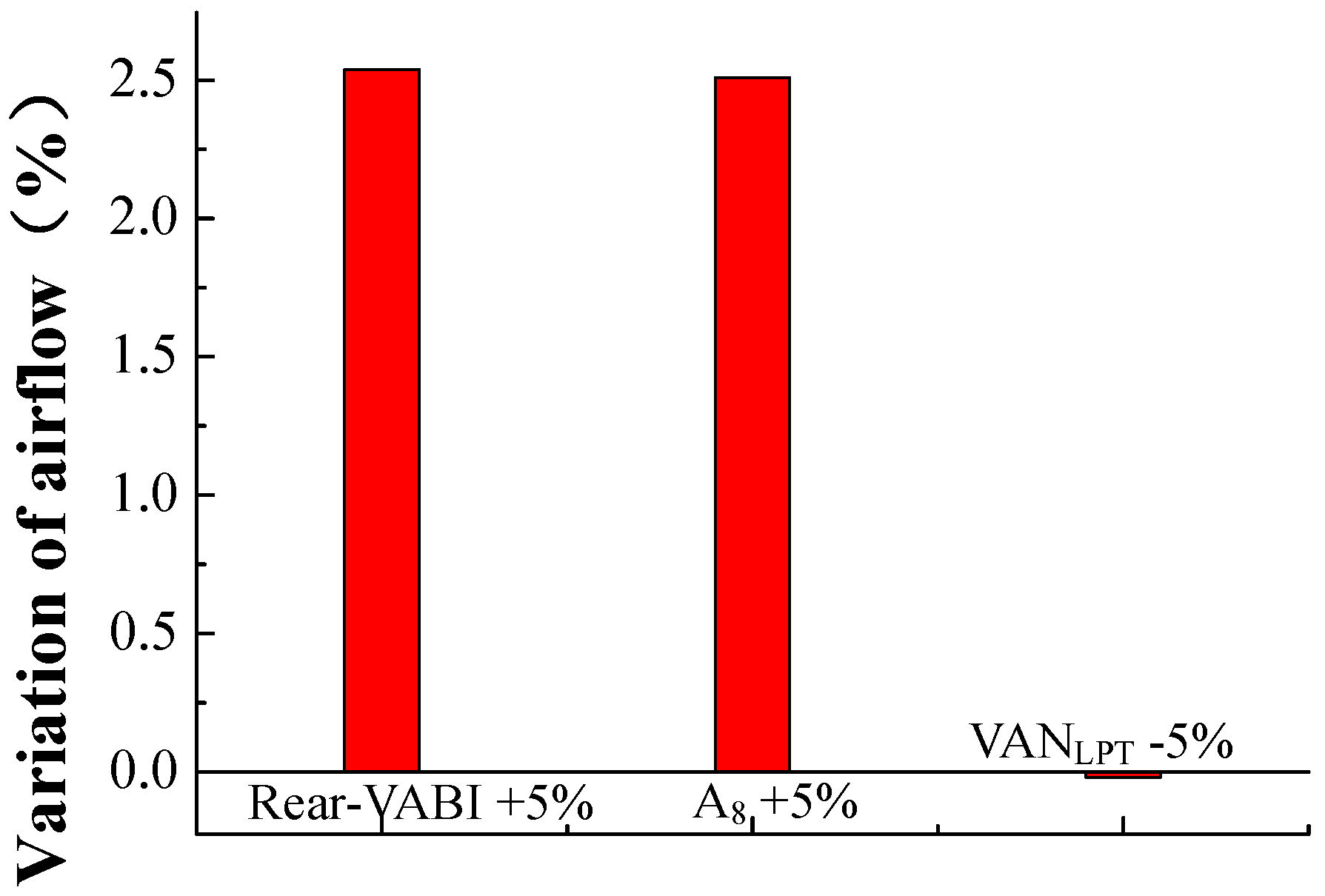
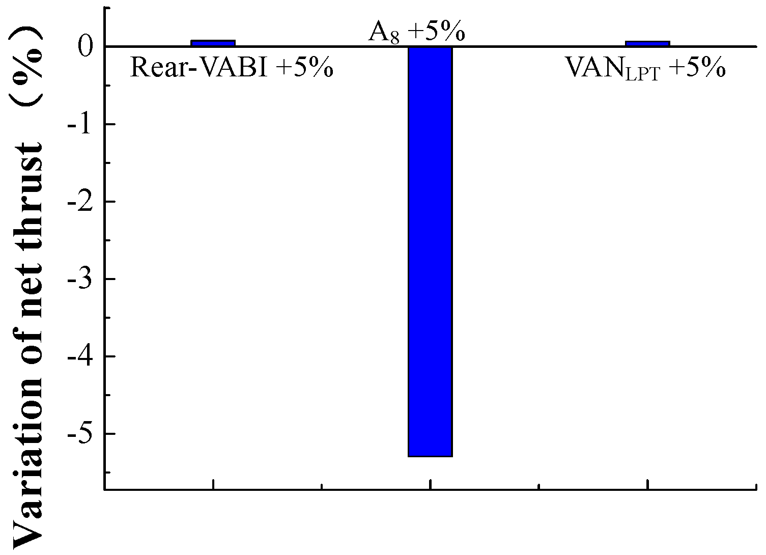
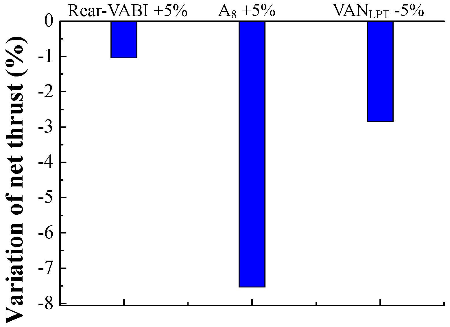
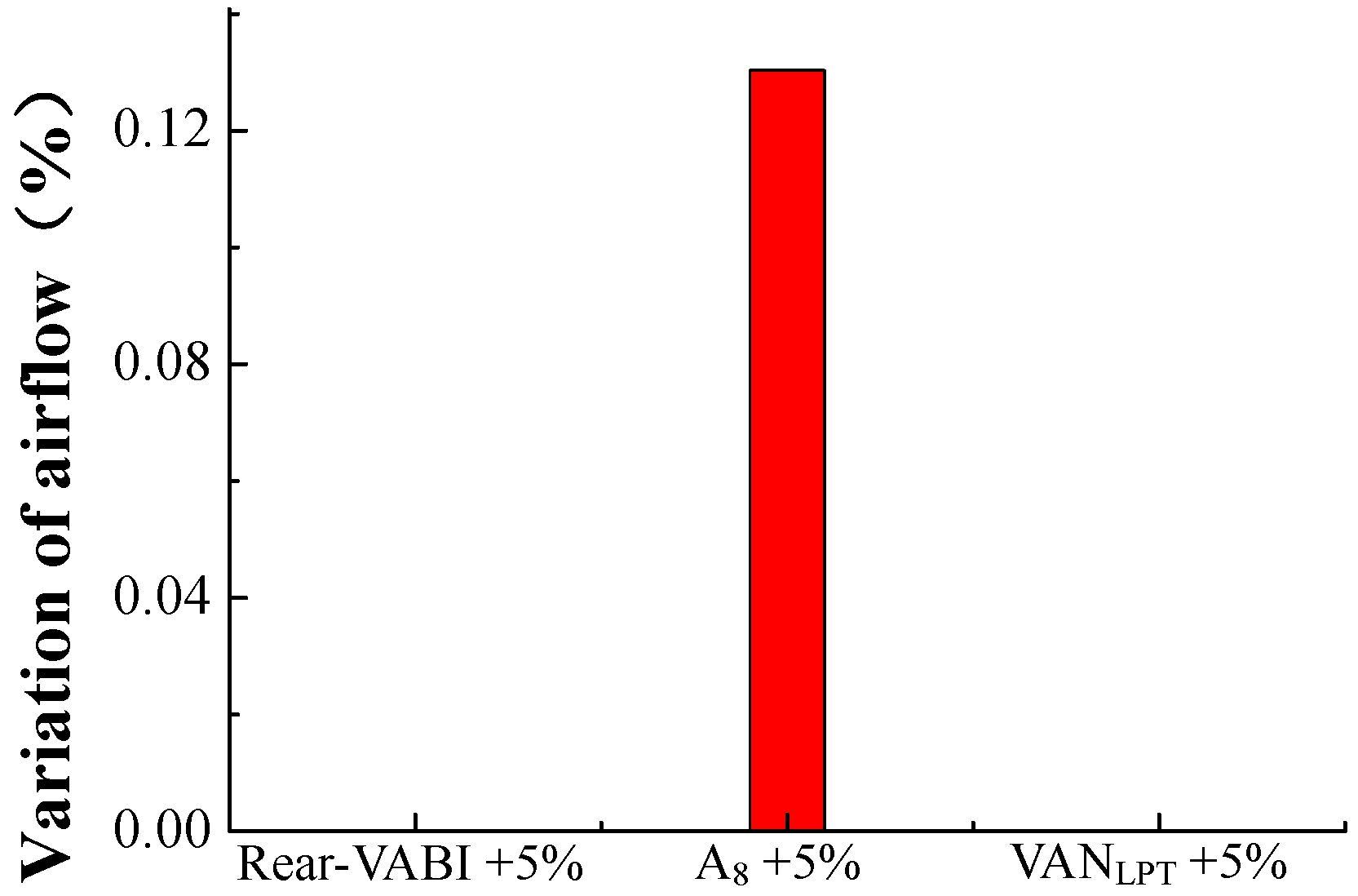
When the engine operates at double bypass mode and LPRS is kept constant, turning down VAN
LPT can decrease T
t4 and thrust. Directly, turning down VAN
LPT leads to the increase of LPT expansion ratio. This increase may improve LPT output work. Then, low pressure rotor work balance is broken and the LPRS tends to rise. Hence for a constant LPRS, less fuel should be injected, leading to a drop in T
t4. At the same time, turning down VAN
LPT leads to the decrease in the HPT expansion ratio. Therefore, high pressure rotor work balance is broken as a result of the decrease of HPT output work, which leads to HPRS reduction. This reduction drives more airflow into core bypass, increasing B
1. Thus, increased total bypass ratio and reduced T
t4 cause the net thrust to decrease. Then, CDFS suction capacity decreases, while front fan outlet back pressure increases. Finally, the front fan pressure ratio rises and engine airflow decreases, which is shown in
Figure 9 and
Figure 10.
As a result of the constant LPRS, turning up Rear-VABI can decrease the thrust due to lower T
t4. Directly, turning up Rear-VABI drives more airflow into core bypass increases B
1, while increasing CDFS flow capacity. Then, variable fan and front fan outlet back pressure decreases, which reduces low pressure compression work. Therefore, an increase trend of LPRS occurs because of the excess of LPT output work for less low pressure compression work. Hence for a constant LPRS, less fuel should be injected. Furthermore, declined T
t4 leads to the reduced net thrust. As for the front fan, the working point moves down slightly along the referred speed line. As shown in
Figure 9 and
Figure 10, the corrected flow of the front fan increases, while the engine airflow rises.
When the engine operates at double bypass mode and LPRS is maintained constant, turning up A
8 decreases T
t4 and reduces thrust. Directly, turning up A
8 drives more air flowing into core bypass increases B
1, while increasing CDFS flow capacity. Then, the variable fan and front fan outlet back pressure decreases, which reduces low pressure compression work. Meanwhile, turning up A
8 leads to the increase of LPT expansion ratio. As a result, LPT output work increases leading to a break in low pressure rotor work balance. An increased trend of LPRS occurs owning to this break. Hence, for a constant LPRS, less fuel should be injected. Finally, T
t4 declines, which results in the reduction of net thrust. As for the front fan, the working point moves down slightly along the referred speed line. As shown in
Figure 9 and
Figure 10, the corrected flow of the front fan increases, while the engine airflow rises.
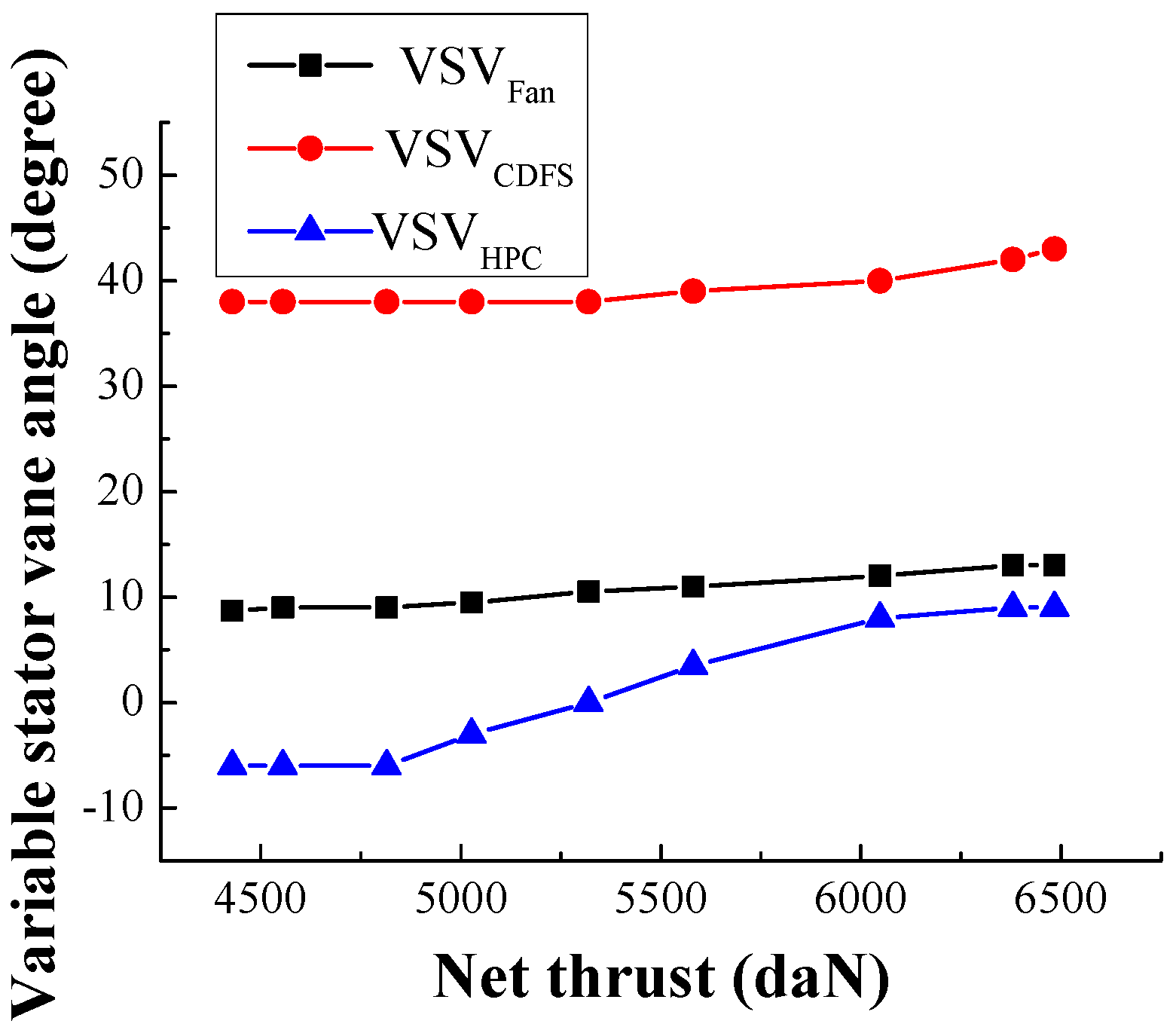
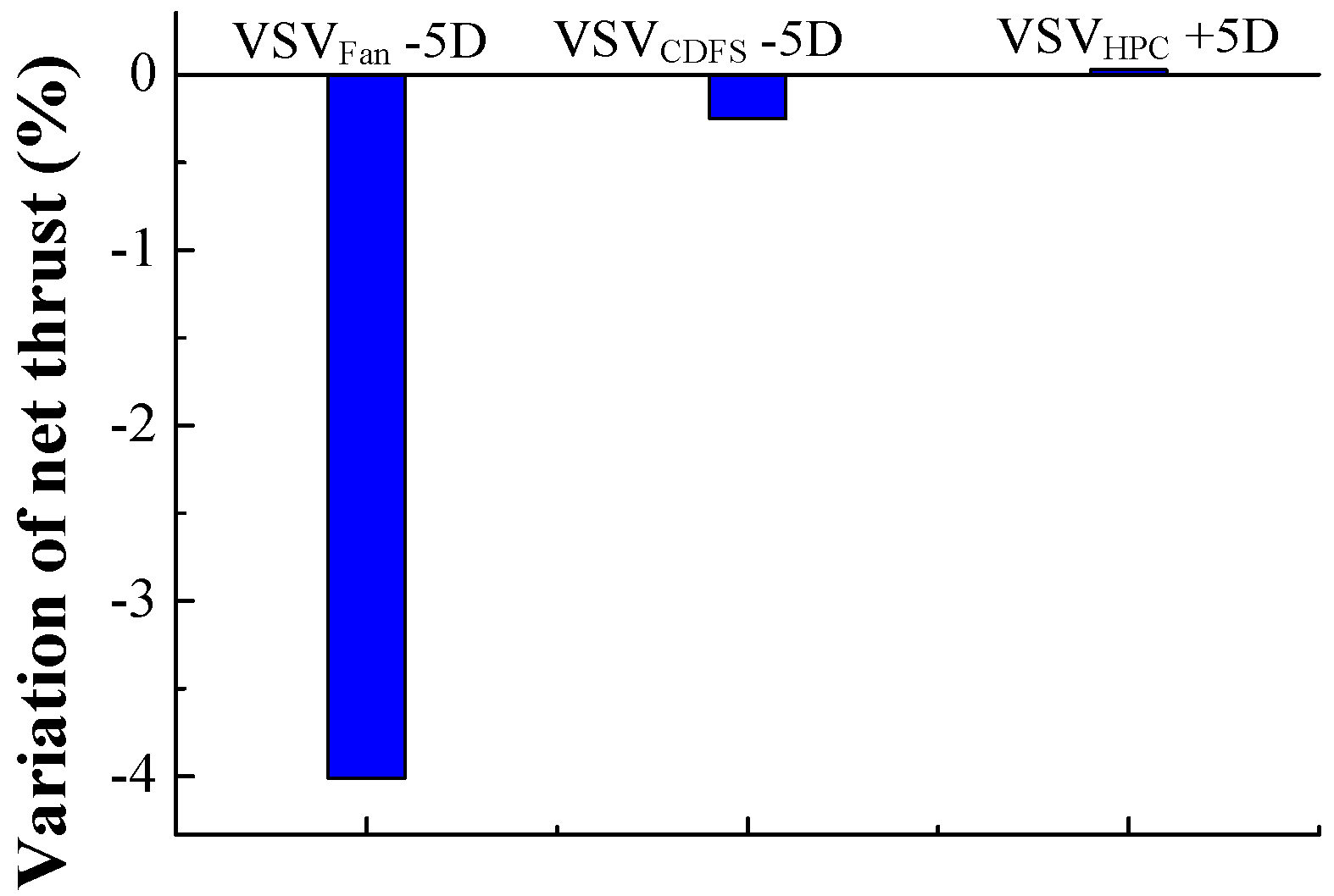
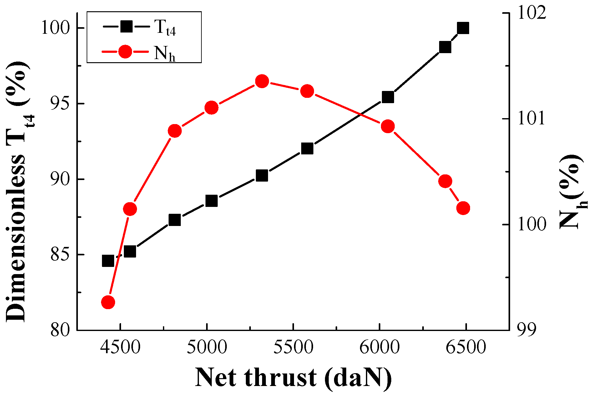
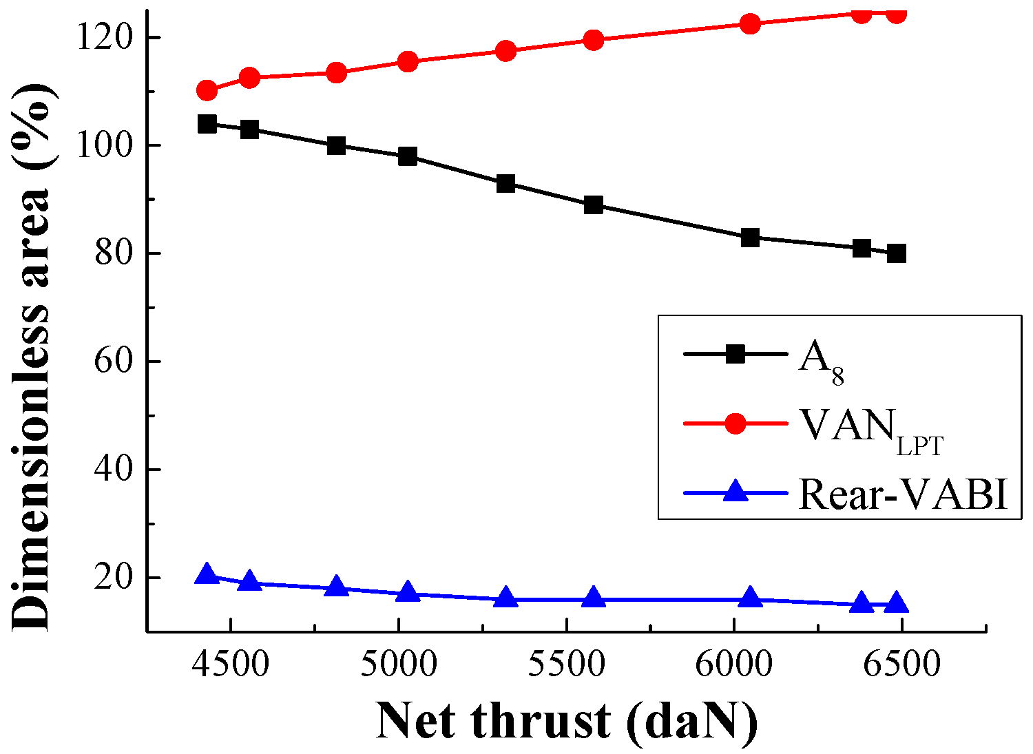
Based on the sensitivity analysis mentioned above, the variable geometry adjustment is researched combining the basic engine working principle analysis during the supersonic cruise in this section.
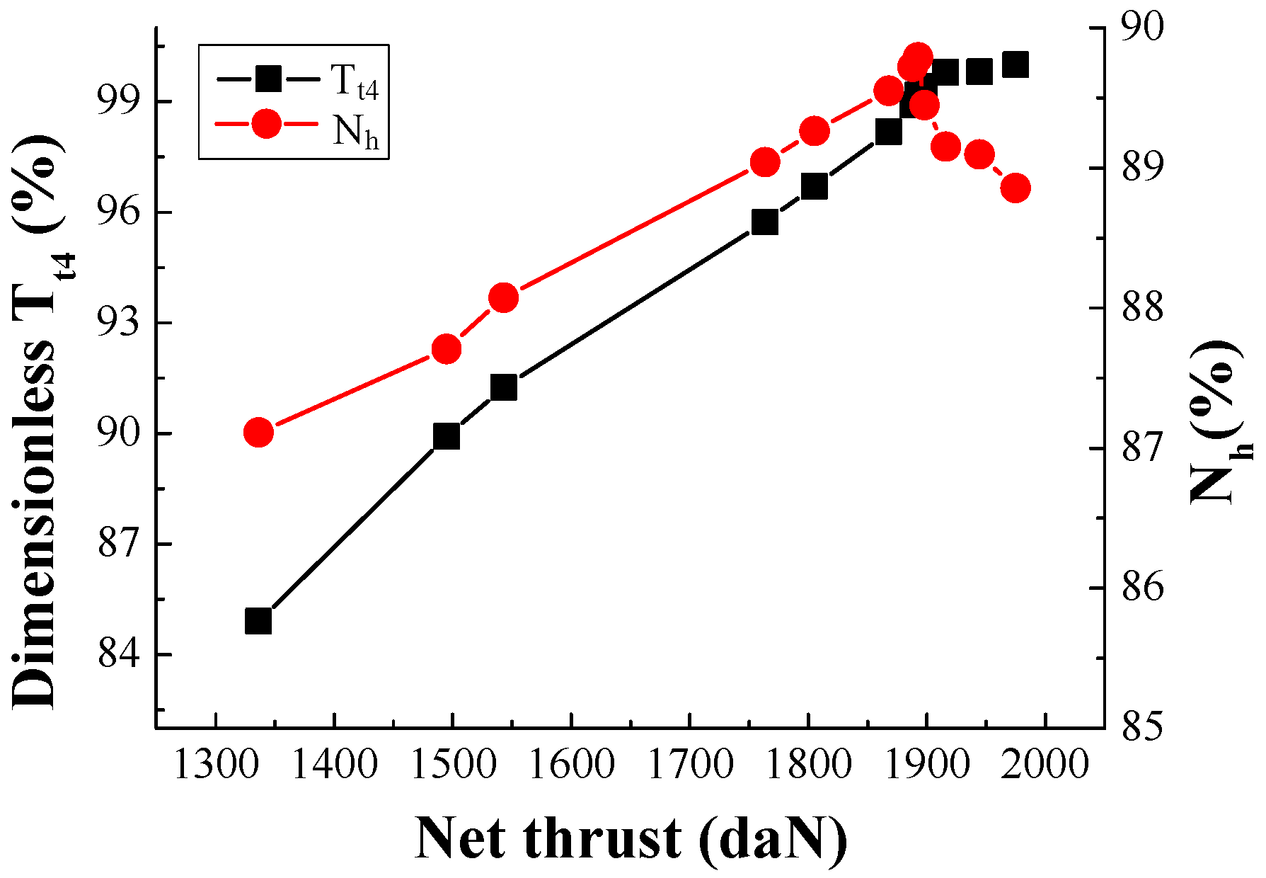
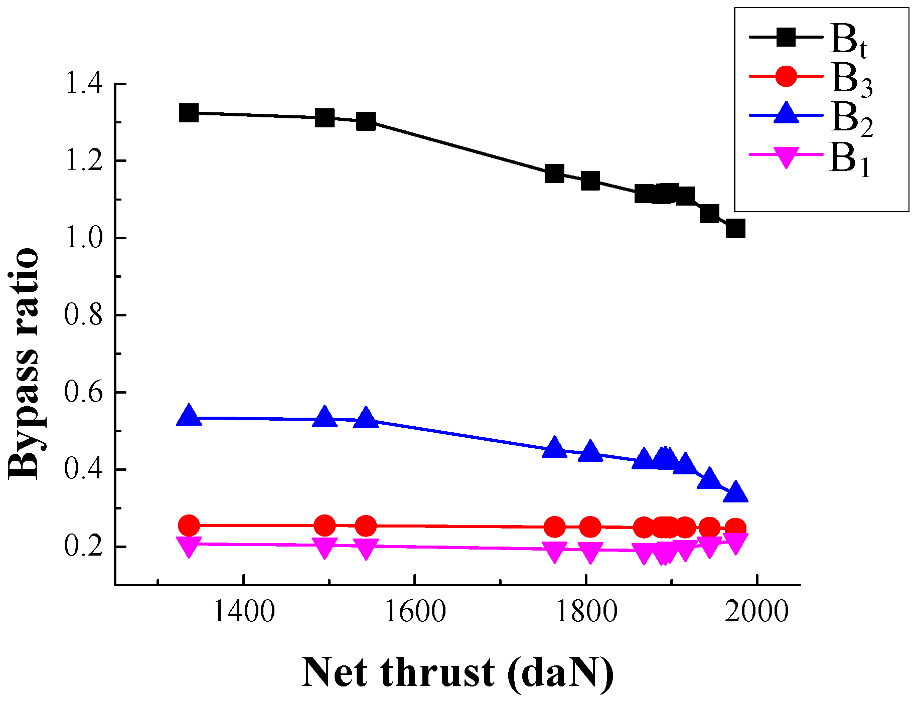
According to the basic engine working principle, the essence of maintaining airflow during throttling decreases the specific thrust by modulating variable geometries along with increased total bypass ratio, lower exit total pressure and temperature of LPT and bypass duct. Turning down VSV
Fan, VSV
CDFS and VSV
HPC can drive a larger percentage of the airflow through the bypass streams, increasing total bypass ratio. As the total bypass ratio increases, air flow through the engine core is reduced. Then, LPT output work decreases. This is caused by declined working airflow. The decreased LPT output work will lead to a break in the low pressure rotor work balance. As a result, turning up A
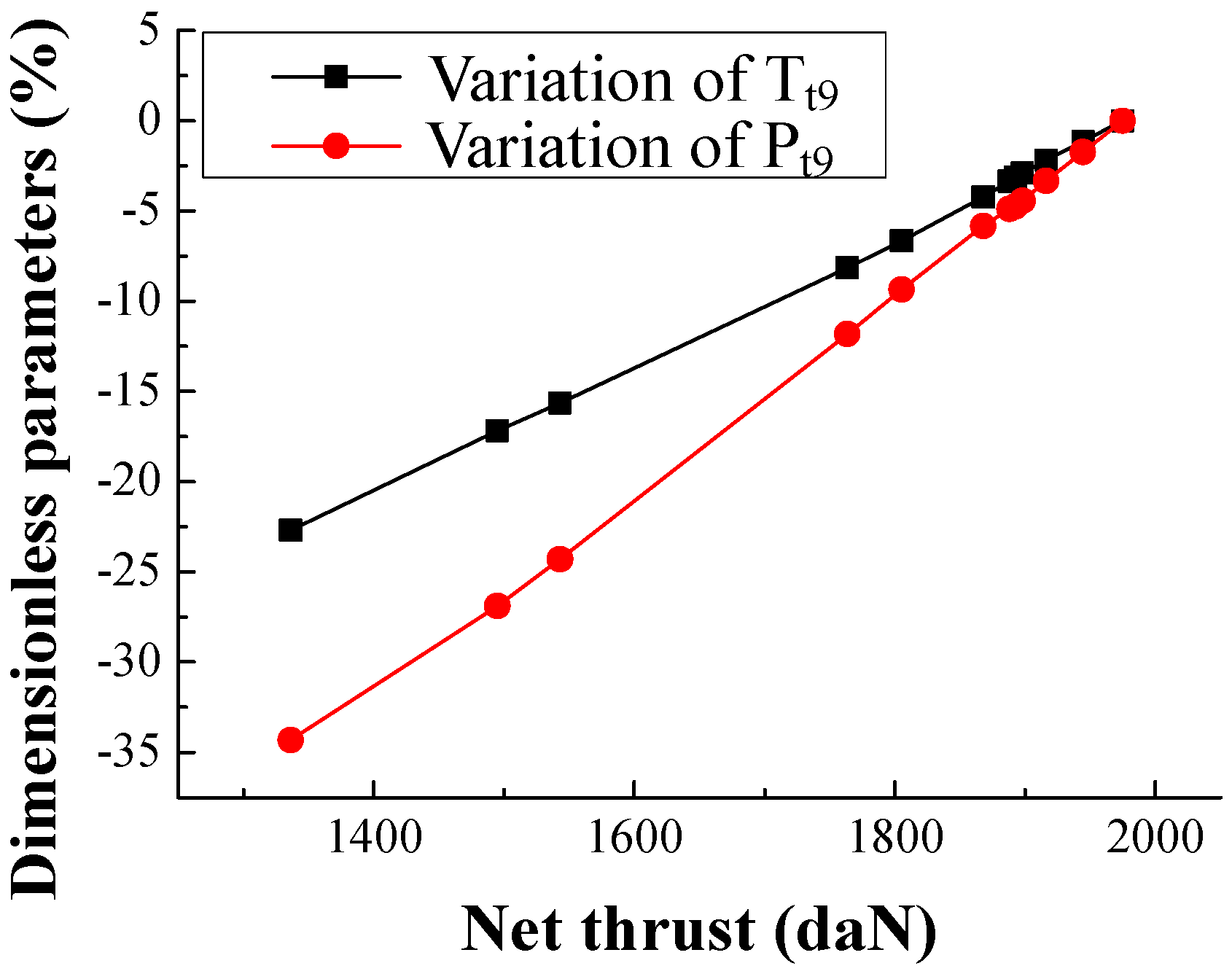
8 can enlarge the LPT expansion ratio to maintain a low pressure rotor work balance. Due to the constraint of a reasonable value of turbine expansion ratio, turning down VAN
LPT appropriately can let LPT work efficiently and obtain suitable T
t4. As a result of the decline of HPT expansion ratio caused by VAN
LPT reduction, T
t4 will be higher to satisfy the high pressure rotor work balance. Meanwhile, turning down VSV
Fan, VSV
CDFS and VSV
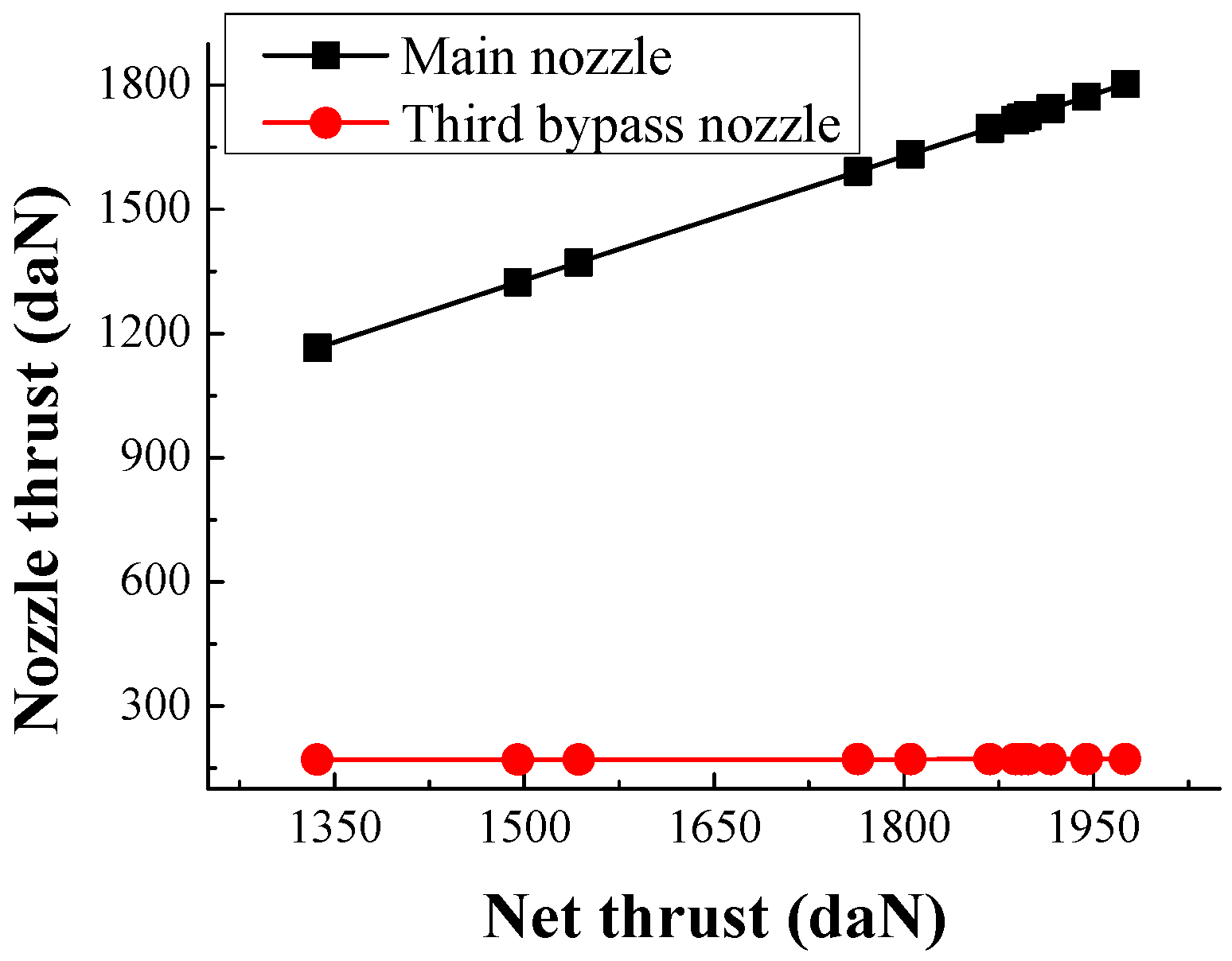
HPC will reduce the compressor pressure ratio. Therefore, due to the increased LPT expansion ratio and decreased compressor pressure ratio, exit total pressure and temperature of LPT and bypass duct will reduce logically. Finally, exit total pressure and temperature of the main nozzle will decline, resulting in the reduced specific thrust. Based on the valuable guidance and advice as stated above, the variable geometries’ modulation is viable for retaining airflow during throttling, which is shown in
Figure 11 and
Figure 12.
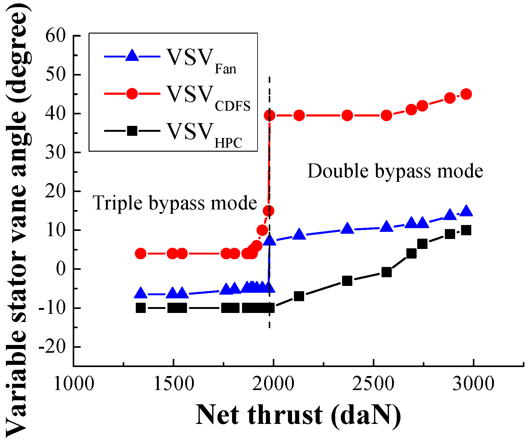
3.2. Study on the Variable Geometries Modulation during Subsonic Cruise
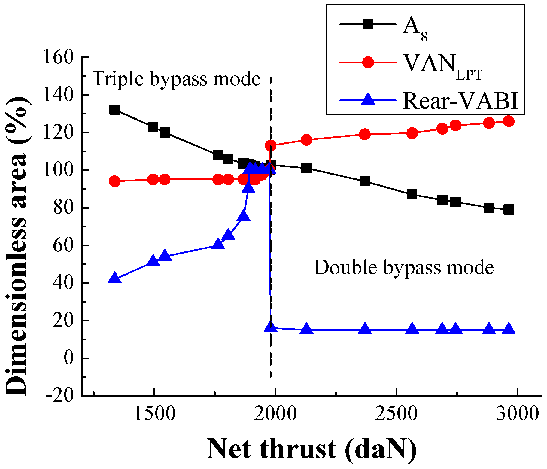
Since the essence of maintaining airflow during throttling is decreasing the specific thrust, it is viable to keep the engine airflow almost constant with reduced thrust via transforming from double bypass mode with low bypass ratio to triple bypass mode with high bypass ratio during subsonic cruise. When high specific thrust is required in flight mission, ACE operates at double bypass mode and decreases its thrust during throttling by modulating variable geometries. When the cruise required thrust is further reduced, ACE transforms from double bypass mode to triple bypass mode. Then, ACE can keep airflow constant during subsonic cruise furthered throttling by modulating variable geometries. Therefore, thrust can decrease continuously during mode transformation but airflow is able to be maintained at a constant level during subsonic cruise throttling.
When ACE operates at double bypass mode during subsonic throttling, variable geometries regulation is similar to the adjustment during supersonic throttling instead of the Rear-VABI. Due to the lower engine inlet total temperature, the inlet total temperature of HPC becomes lower during the subsonic cruise. During throttling, HPRS rises along with turning down VSVCDFS. Therefore, the corrected speed of HPC will be out of the reasonable value during subsonic throttling at double bypass mode. Based on the engine working principle, turning down Rear-VABI can increase the total temperature of HPC, which solves the above-mentioned problem. However, the adjustment of Rear-VABI is restricted and has been minimized. Consequently, the Rear-VABI remains unchanged, in contrast with the adjustment during supersonic throttling.
This section mainly introduces the regulation of variable geometries during subsonic cruise throttling at triple bypass mode whose working condition is set as 11 km, 0.8 Ma. According to the quantitative research and components matching mechanisms, sensitivity analysis of six variable geometries (VSV
Fan, VSV
CDFS, VSV
HPC, Rear-VABI, VAN
LPT and A
8) modulation on the engine airflow and net thrust can be obtained. When the engine operates at triple bypass mode and LPRS is constant, as stated earlier, the reduction of variable fan flow capacity by turning down VSV
Fan can decrease the thrust due to lower T
t4. At the same time, turning down VSV
CDFS decreases T
t4 and net thrust. The effect of turning down VSV
Fan and VSV
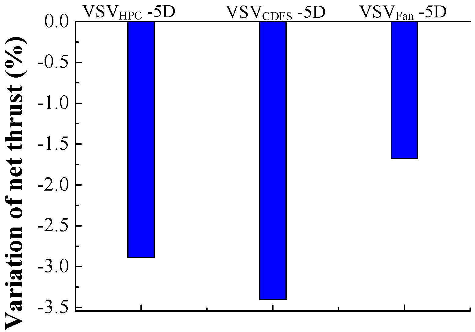
CDFS on airflow and net thrust is similar to the effect at double bypass mode. According to the histogram in
Figure 13 and
Figure 14, although turning down VSV
Fan can cause a significant reduction of net thrust, VSV
Fan also has a great influence upon airflow. Therefore, the modulation of VSV
Fan should be controlled appropriately to maintain airflow as thrust reduces during the subsonic cruise.
When the LPRS is kept constant, the rise of HPC flow capacity by turning up VSV
HPC will increase the thrust due to higher T
t4. This increase induces more air flow into engine core, decreasing B1, while increasing the flow through the engine core. Then, the required compression work of HPC rises and the distributing compression work of CDFS reduces, which declines CDFS suction capacity and hence air flow. Thus, the outlet back pressure of the variable fan increases, which results in the rise of the variable fan pressure ratio, and the engine airflow decreases. Meanwhile, the low pressure compression work increases. Then, a decrease trend of LPRS occurs because of the reduced LPT output work and higher low pressure compression work. Hence, for a constant LPRS, more fuel should be injected, while T
t4 rises. Finally, the specific thrust increases, leading to the net thrust rising, which is shown in
Figure 13 and
Figure 14. Although it is beneficial to turn down VSV
HPC for constant airflow during throttling, VSV
HPC will remain unchanged due to the minimum regulation constraint.
At triple bypass mode, turning up VAN
LPT will increase thrust due to lower bypass ratio. Directly turning up VAN
LPT leads to the rise of HPT expansion ratio. This increase may improve HPT output work. Then, the high pressure rotor work balance is broken and as a result the HPRS tends to rise. Therefore, CDFS suction capacity increases, while the variable fan outlet back pressure decreases. Finally, low pressure compression work reduces. Further, an increased trend of LPRS occurs because of the excess of LPT output work and less low pressure compression work. Hence, for a constant LPRS, less fuel should be injected, which leads to T
t4 declining. Finally, due to the combined effects of lower bypass ratio and higher T
t4, net thrust rises. Because of the changeless pressure ratio of the front fan, airflow is almost the same as shown in
Figure 15 and
Figure 16. Since airflow is insensitive to VAN
LPT, it is beneficial to turn down VAN
LPT for constant airflow during throttling.
When the engine operates at triple bypass mode and LPRS is maintained at a constant level, turning up A
8 decreases T
t4 and therefore reduces thrust. The effect of turning up A
8 on airflow and net thrust is similar to the effect at the double bypass mode. According to the histogram in
Figure 15 and
Figure 16, turning up A
8 can reduce net thrust and increase airflow effectively. Consequently, under the premise of satisfying the constraints, it is worth turning up A
8 during throttling.
When the engine operates at triple bypass mode and LPRS is constant, as stated earlier, turning up Rear-VABI will increase the thrust due to higher T
t4. Directly, turning up Rear-VABI drives more air flowing into core bypass and increases B
1, while reducing engine core airflow. Meanwhile, turning up Rear-VABI leads to the decline of LPT expansion ratio. Therefore, a decreased trend of LPRS occurs because of the lower LPT output work. Hence, for a constant LPRS, more fuel should be injected. Further, as shown in
Figure 15, higher T
t4 leads to an increased net thrust. Because of the changeless pressure ratio of the front fan, airflow is almost the same, which is shown in
Figure 16. Since airflow is insensitive to Rear-VABI, it is beneficial to turn down Rear-VABI for constant airflow.
Based on the sensitivity analysis mentioned above, the variable geometry adjustment is researched, combining the basic engine working principle analysis during the subsonic cruise in this section.
According to the basic engine working principle, the essence of maintaining airflow during throttling is to decrease the specific thrust by modulating variable geometries along with increased total bypass ratio, lower exit total pressure and lower temperature of LPT. Turning down VSV
Fan and VSV
CDFS can induce a larger percentage of the total airflow through the bypass streams with increased total bypass ratio. As the total bypass ratio increases, flow through the engine core is reduced. Then, LPT output work decreases. This is caused by declined working airflow. The decreased LPT output work will lead to a break in the low pressure rotor work balance. As a result, turning up A
8 can enlarge the LPT expansion ratio to maintain a low pressure rotor work balance. Due to the constraint of the reasonable value of the turbine expansion ratio, turning down VAN
LPT appropriately can let LPT work efficiently and obtain suitable T
t4. As a result of the decline of HPT expansion ratio caused by VAN
LPT reduction, T
t4 will be higher to satisfy high pressure rotor work balance. Meanwhile, turning down VSV
Fan and VSV
CDFS will reduce the compressor pressure ratio. Therefore, as a result of the enlarged LPT expansion ratio and decreased compressor pressure ratio, the exit total pressure and temperature of LPT and bypass duct will reduce logically. Finally, the exit total pressure and temperature of the main nozzle will decline, resulting in the reduced specific thrust. Based on the valuable guidance and advice as stated earlier, the variable geometries’ modulation schedule is obtained regarding retaining airflow during throttling, which is shown in
Figure 17 and
Figure 18.


