
A New Kinematic Model of Portable Articulated Coordinate Measuring Machine


Abstract
:
1. Introduction
2. Model
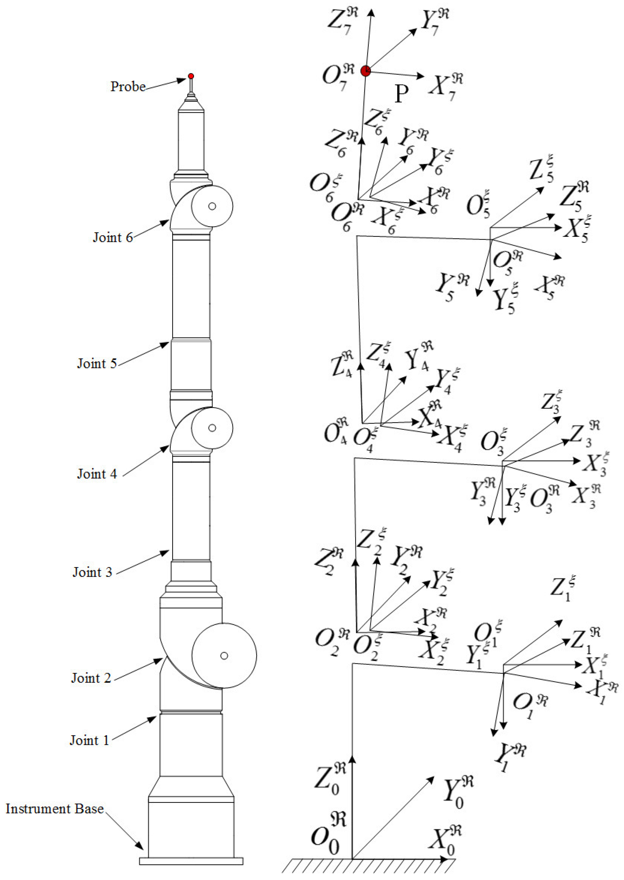
2.1. D-H Conventions
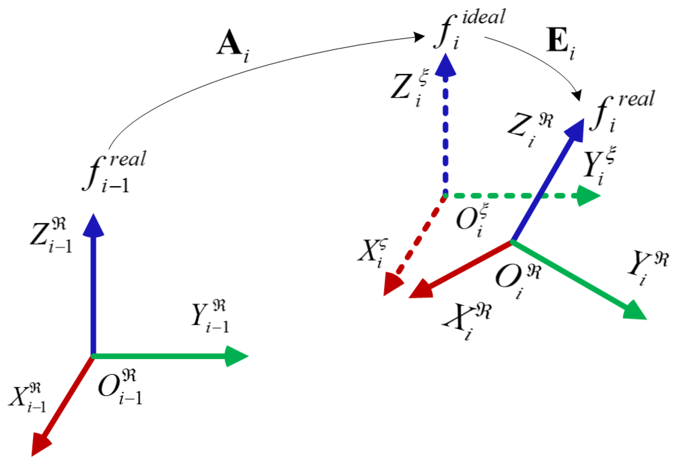
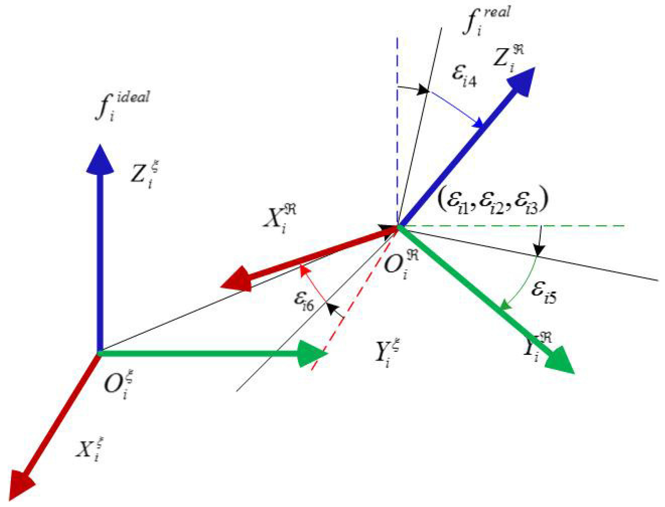
2.2. Generalized Geometric Error Theory
2.3. Kinematic Model Based on Generalized Geometric Error Theory
3. Error Model and Calibration Algorithm
3.1. Error Model
3.2. Calibration Algorithm
- Step 1:
- Set the initial estimation values vector of generalized geometric error parameters vector ε, the initial damping factor , permissible error , set the flag of the iteration step and the growth factor or 10;
- Step 2:
- Calculate , , ;
- Step 3:
- Solve ;
- Step 4:
- Calculate , , ;
- Step 5:
- If , vector is supposed to as the best estimate , else ;
- Step 6:
- If , then , go to Step 2, else , go to Step 3.
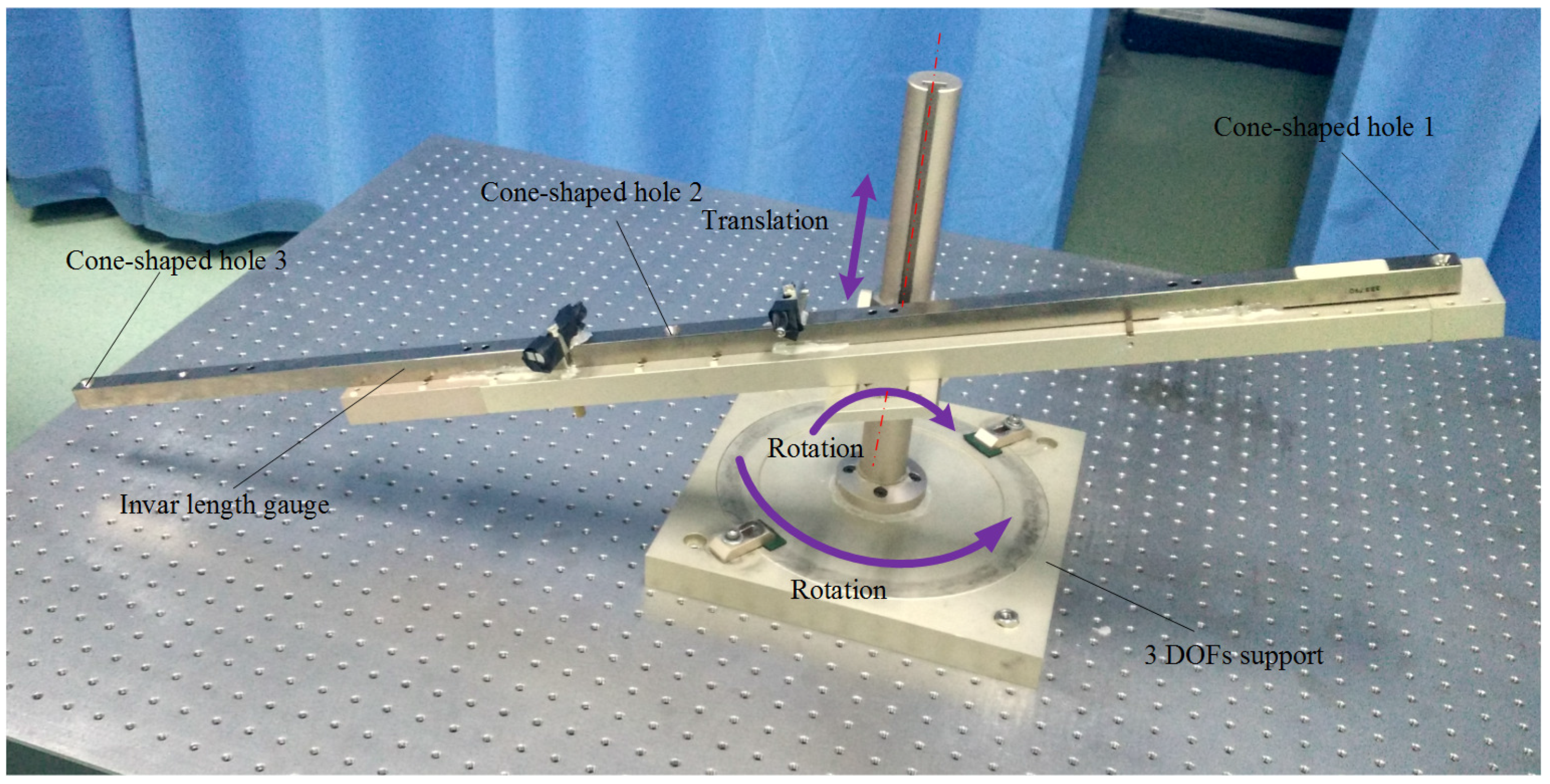
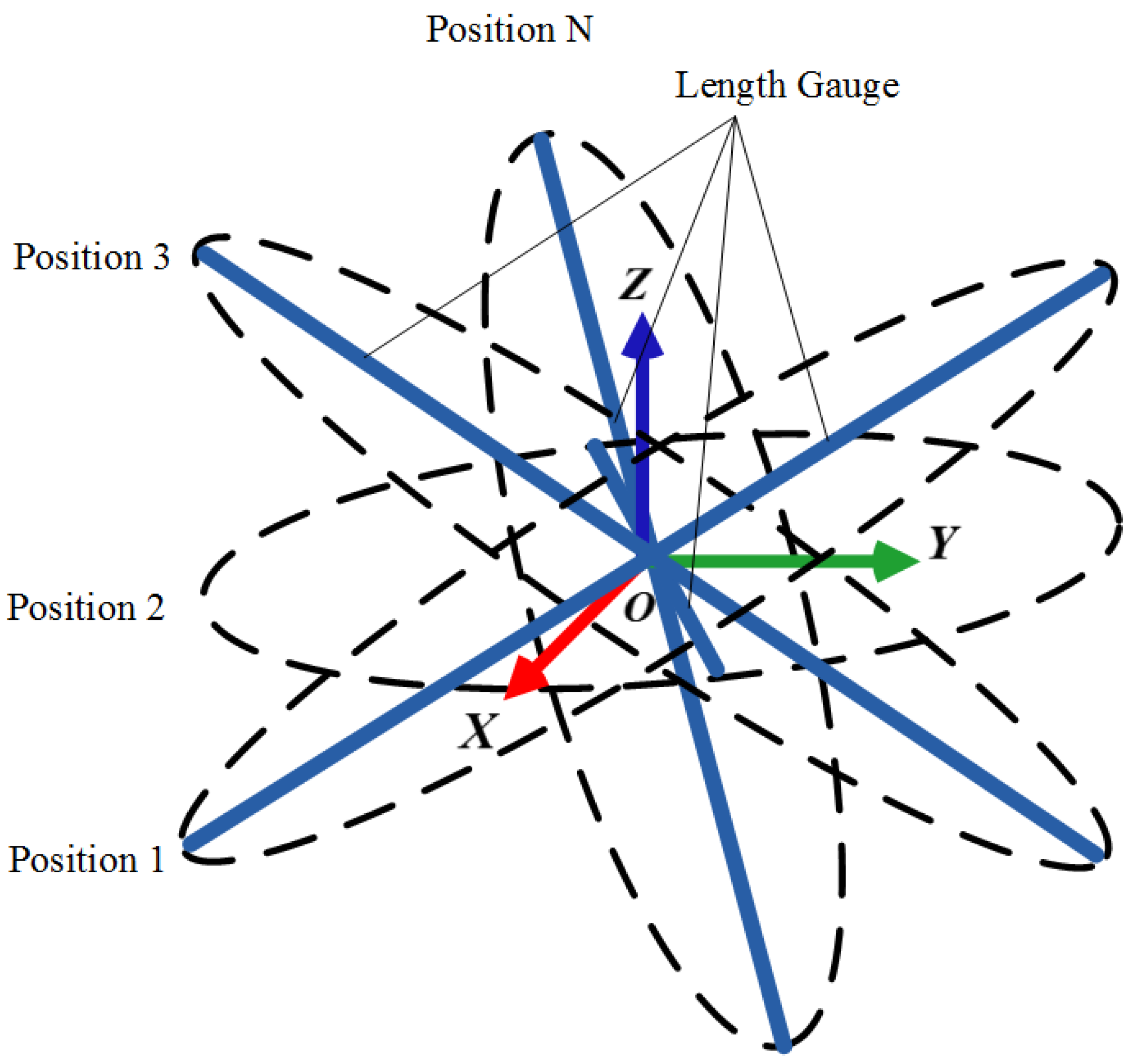
4. Sample Strategy
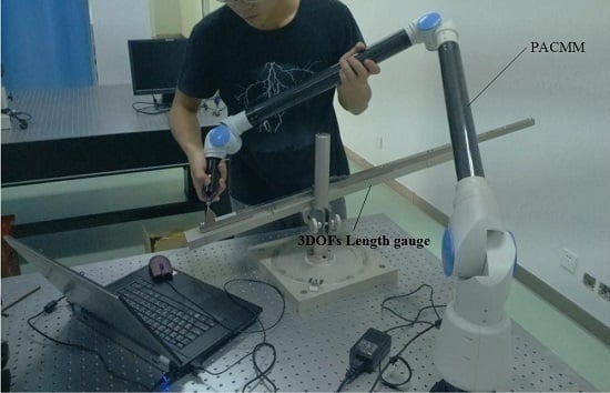
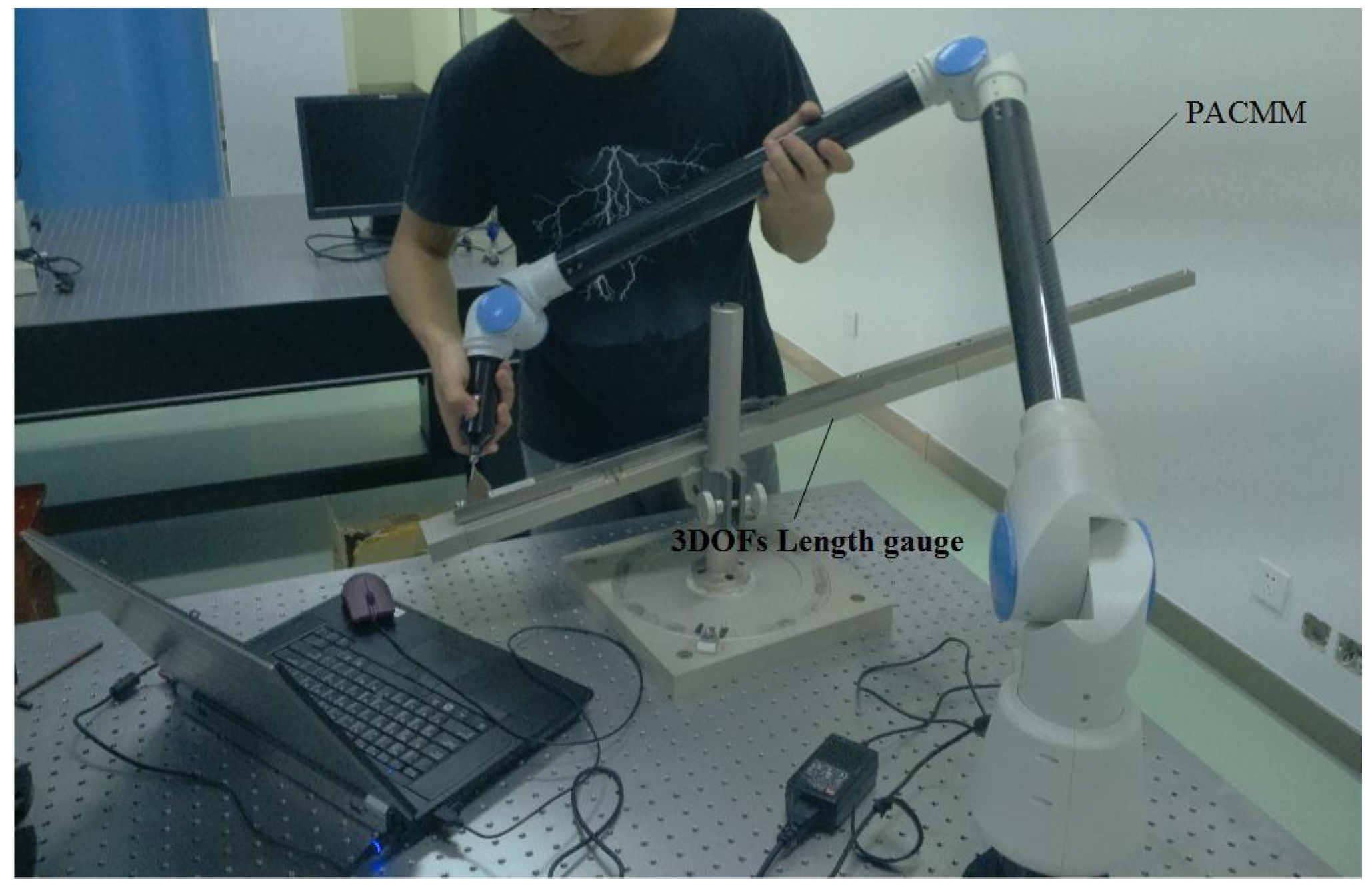
5. Experiment
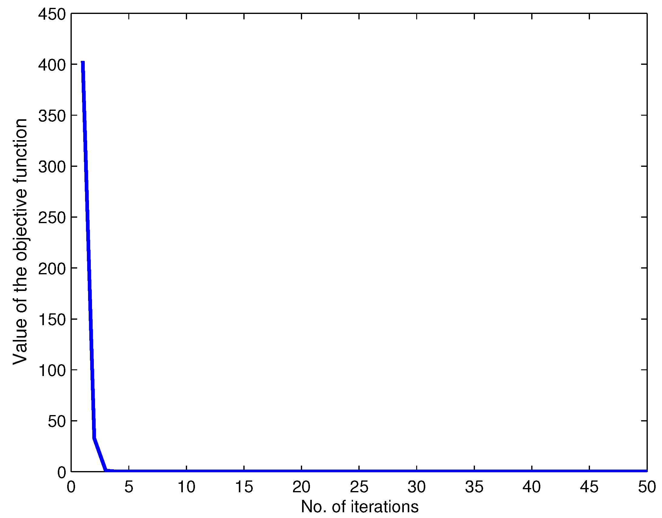
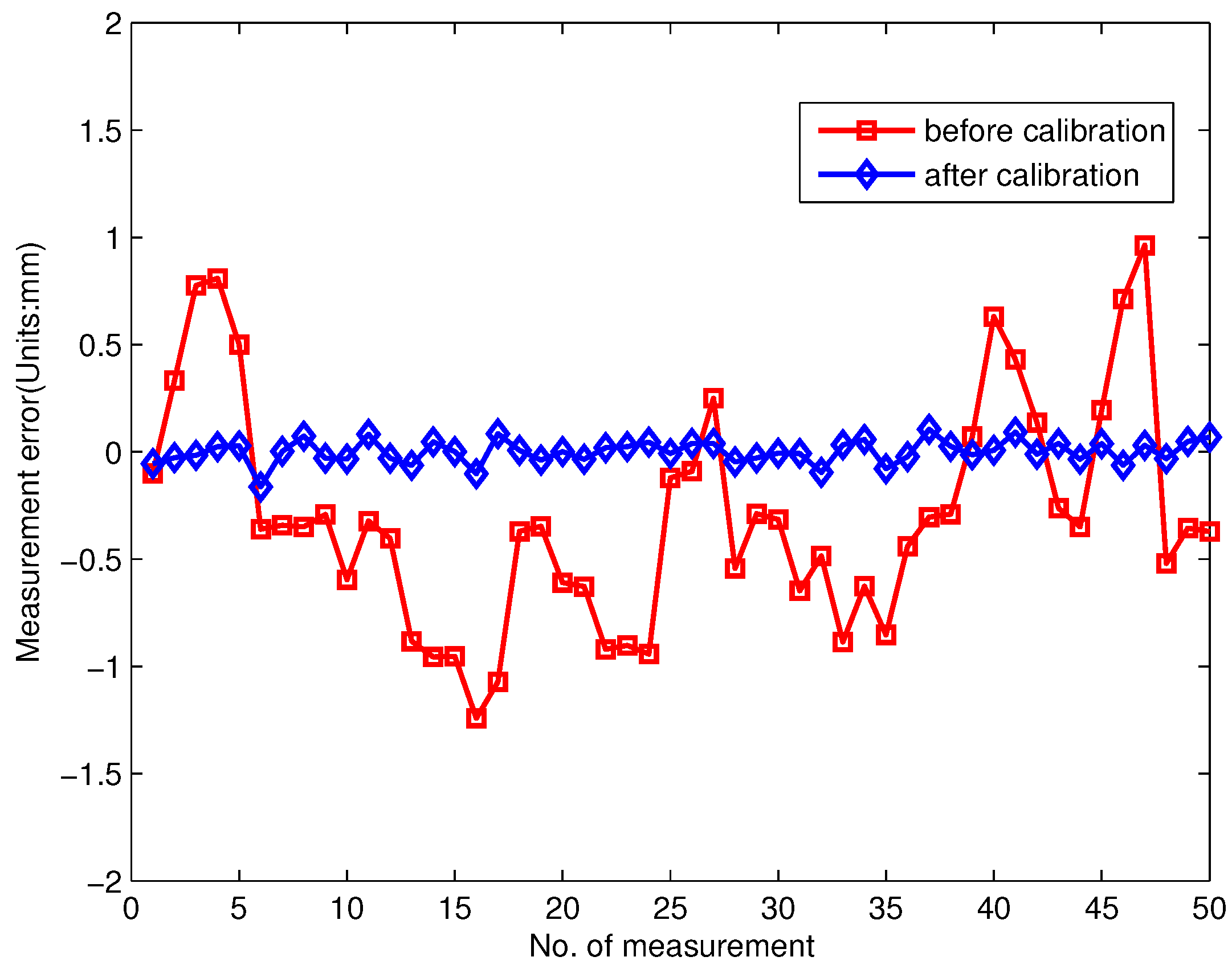
5.1. Calibration
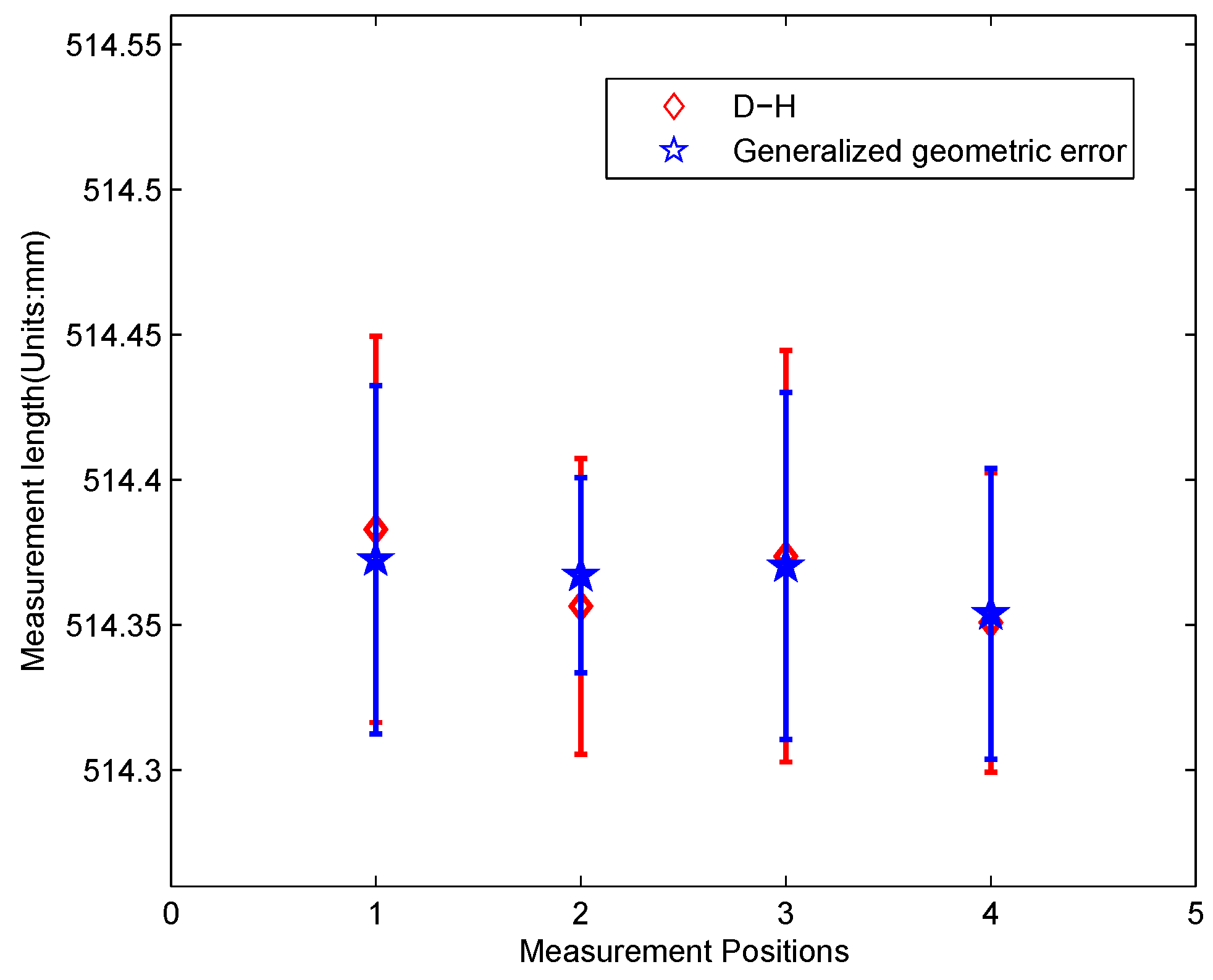
5.2. Comparison
6. Discussion
7. Conclusions
Acknowledgments
Author Contributions
Conflicts of Interest
Abbreviations
| PACMM | Portable Articulated Coordinate Measuring Machine |
| CMM | Coordinate Measuring Machine |
| D-H | Denavit-Hartenberg |
| L-M | Levenberg-Marquard |
| 1D | one-dimensional |
| DOF | degree of freedom |
| GA | Genetic Algorithm |
| PSO | Particle Swarm Optimization |
| SA | Simulated Annealing |
References
- Yu, L.D.; Zhao, H.N.; Zhang, W.; Li, W.S.; Deng, H.X.; Song, Y.T.; Gu, Y.Q. Development of precision measurement network of experimental advanced superconducting tokamak. Opt. Eng. 2014, 52, 26–31. [Google Scholar] [CrossRef]
- Joubair, A.; Slamani, M.; Bonev, I.A. A novel XY-Theta precision table and a geometric procedure for its kinematic calibration. Robot. Comput.-Integr. Manuf. 2012, 28, 57–65. [Google Scholar] [CrossRef]
- Chen, I.M.; Yang, G.; Tan, C.T.; Yeo, S.H. Local POE model for robot kinematic calibration. Mech. Mach. Theory 2001, 36, 1215–1239. [Google Scholar] [CrossRef]
- Denavit, J.; Hartenberg, R.S. A kinematic notation for lower-pair mechanisms based on matrices. ASME J. Appl. Mech. 1955, 22, 215–221. [Google Scholar]
- Hayati, S.A. Robot arm geometric link parameter estimation. In Proceedings of the 22nd IEEE Conference on Decision and Control, San Antonio, TX, USA, 14–16 December 1983; pp. 1477–1483.
- Judd, R.P.; Knasinski, A.B. A technique to calibrate industrial robots with experimental verification. IEEE Trans. Robot. Autom. 1990, 6, 20–30. [Google Scholar] [CrossRef]
- Veitschegger, W.K.; Wu, C.H. Robot calibration and compensation. IEEE J. Robot. Autom. 1988, 4, 643–656. [Google Scholar] [CrossRef]
- Zhuang, H.; Roth, Z.S.; Hamano, F. A complete and parametrically continuous kinematic model for robot manipulators. IEEE Trans. Robot. Autom. 1992, 8, 451–463. [Google Scholar] [CrossRef]
- Roth, Z.S.; Mooring, B.; Ravani, B. An overview of robot calibration. IEEE J. Robot. Autom. 1987, 3, 377–385. [Google Scholar] [CrossRef]
- Meggiolaro, M.A.; Dubowsky, S.; Mavroidis, C. Geometric and elastic error calibration of a high accuracy patient positioning system. Mech. Mach. Theory 2005, 40, 415–427. [Google Scholar] [CrossRef]
- Tian, W.; Gao, W.; Zhang, D.; Huang, T. A general approach for error modeling of machine tools. Int. J. Mach. Tools Manuf. 2014, 79, 17–23. [Google Scholar] [CrossRef]
- American Society of Mechanical Engineering (ASME). Methods for Performance Evaluation of Articulated Arm Coordinate Measuring Machines; AMSE B89.4.22; American Society of Mechanical Engineering: New York, NY, USA, 2005; pp. 1–45. [Google Scholar]
- Verein Deutscher Ingenieure (VDI). Acceptance and Reverification Test for Articulated Arm Coordinate Measuring Machines; VDI/VDE 2617 Part 9; Verein Deutscher Ingenieure: Düsseldorf, Germany, 2009; pp. 1–20. [Google Scholar]
- International Organization for Standardization. Geometrical Product Specifications (GPS)—Acceptance and Reverification Tests for Coordinate Measuring Systems (CMS)—Part 12: Articulated Arm Coordinate Measurement Machines (CMM); ISO/CD 10360-12; ISO: Geneva, Switzerland, 2014; pp. 1–42. [Google Scholar]
- Furutani, R.; Shimojima, K.; Takamasu, K. Kinematical calibration of articulated CMM using multiple simple artifacts. In Proceedings of the 17th IMEKO World Congress, Dubrovnik, Croatia, 22–27 June 2003; pp. 1789–1801.
- Santolaria, J.; Aguilar, J.J.; Yagüe, J.A.; Pastor, J. Kinematic parameter estimation technique for calibration and repeatability improvement of articulated arm coordinate measuring machines. Precis. Eng. 2008, 32, 251–268. [Google Scholar] [CrossRef]
- Nguyen, H.N.; Zhou, J.; Kang, H.J. A new full pose measurement method for robot calibration. Sensors 2013, 13, 9132–9147. [Google Scholar] [CrossRef] [PubMed]
- Kovač, I.; Frank, A. Testing and calibration of coordinate measuring arms. Precis. Eng. 2001, 25, 90–99. [Google Scholar] [CrossRef]
- Shimojima, K.; Furutani, R.; Takamasu, K.; Araki, K. The estimation method of uncertainty of articulated coordinate measuring. In Proceedings of the 2002 IEEE International Conference on Industrial Technology (IEEE ICIT ’02), Bangkok, Thailand, 11–14 December 2002; Volume 1, pp. 411–415.
- Piratelli-Filho, A.; Lesnau, G.R. Virtual spheres gauge for coordinate measuring arms performance test. Measurement 2010, 43, 236–244. [Google Scholar] [CrossRef]
- González-Madruga, D.; Cuesta, E.; Patiño, H.; Barreiro, J.; Martinez-Pellitero, S. Evaluation of AACMM Using the Virtual Circles Method. Procedia Eng. 2013, 63, 243–251. [Google Scholar] [CrossRef]
- Acero, R.; Brau, A.; Santolaria, J.; Pueo, M. Verification of an articulated arm coordinate measuring machine using a laser tracker as reference equipment and an indexed metrology platform. Measurement 2015, 69, 52–63. [Google Scholar] [CrossRef]
- Li, J.; Yu, L.D.; Sun, J.Q.; Xia, H.J. A Kinematic Model for Parallel-Joint Coordinate Measuring Machine. J. Mech. Robot. 2103, 5, 044501. [Google Scholar] [CrossRef]
- Light, T.V.; Gorlach, I.A.; Schönberg, A.; Schmitt, R. Measuring arm calibration. In Proceedings of the 5th European Conference on European Computing Conference, Paris, France, 28–30 April 2011; pp. 222–227.
- Dong, Z.; Zhang, W.; Zhao, H.N.; Yu, L.D. Structural parameter calibration for parallel dual-joint coordinate measuring machine. Nanotechnol. Precis. Eng. 2015, 13, 287–292. [Google Scholar]
- Gao, G.B.; Wen, W.; Lin, K.; Chen, Z.G. Parameter identification based on modified annealing algorithm for articulated arm CMMs. Opt. Precis. Eng. 2009, 17, 2499–2505. [Google Scholar]
- Liu, W.L.; Qu, X.H.; Yan, Y.G. Self-Calibration and Error Compensation of Flexible Coordinate Measuring Robot. In Proceedings of the 2007 International Conference on Mechatronics and Automation, Harbin, China, 5–8 August 2007; pp. 2489–2494.
- Levenberg, K. A Method for the Solution of Certain Non-linear Problems in Least Squares. Quart. Appl. Math. 1944, 2, 164–168. [Google Scholar]
- Marquardt, D.W. An Algorithm for Least Square Estimation of Non-Linear. J. Soc. Ind. Appl. Math. 1963, 11, 431–441. [Google Scholar] [CrossRef]
- Zhang, T.; Liang, D.; Dai, X. Test of Robot Distance Error and Compensation of Kinematic Full Parameters. Adv. Mech. Eng. 2014, 6, 1–9. [Google Scholar] [CrossRef]
- Borm, J.H.; Menq, C.H. Determination of Optimal Measurement Configurations for Robot Calibration Based on Observability Measure. Int. J. Robot. Res. 1991, 10, 51–63. [Google Scholar] [CrossRef]
- Zheng, D.T.; Xiao, Z.Y.; Xia, X. Multiple Measurement Models of Articulated Arm Coordinate Measuring Machines. Chin. J. Mech. Eng. 2015, 28, 994–998. [Google Scholar] [CrossRef]


| Parameters | ||||||
|---|---|---|---|---|---|---|
| θ (rad) | 0 | −1.57 | −3.33 | −4.57 | −0.97 | −3.96 |
| α (rad) | −π/2 | π/2 | −π/2 | π/2 | −π/2 | π/2 |
| l (mm) | 40 | −40 | 32 | −32 | 32 | −32 |
| d (mm) | 0 | 0 | 440 | 0 | 340 | 0 |
| Parameters | ||||||
|---|---|---|---|---|---|---|
| (mm) | −0.0156 | −0.0060 | −0.0062 | −0.0076 | 0.0164 | −0.0038 |
| (mm) | - | 0.0071 | 0.0081 | −0.0025 | 0.0204 | −0.0017 |
| (mm) | - | - | - | - | - | 0.0247 |
| (rad) | - | 0.0015 | −0.0307 | 0.0443 | −0.0332 | - |
| (rad) | - | 0.0288 | −0.0423 | −0.0318 | −0.0013 | - |
| (rad) | −0.0011 | −0.0021 | 0.0021 | −0.0007 | 0.0018 | - |
© 2016 by the authors; licensee MDPI, Basel, Switzerland. This article is an open access article distributed under the terms and conditions of the Creative Commons Attribution (CC-BY) license (http://creativecommons.org/licenses/by/4.0/).
Share and Cite
Zhao, H.-N.; Yu, L.-D.; Jia, H.-K.; Li, W.-S.; Sun, J.-Q. A New Kinematic Model of Portable Articulated Coordinate Measuring Machine. Appl. Sci. 2016, 6, 181. https://doi.org/10.3390/app6070181
Zhao H-N, Yu L-D, Jia H-K, Li W-S, Sun J-Q. A New Kinematic Model of Portable Articulated Coordinate Measuring Machine. Applied Sciences. 2016; 6(7):181. https://doi.org/10.3390/app6070181
Chicago/Turabian StyleZhao, Hui-Ning, Lian-Dong Yu, Hua-Kun Jia, Wei-Shi Li, and Jing-Qi Sun. 2016. "A New Kinematic Model of Portable Articulated Coordinate Measuring Machine" Applied Sciences 6, no. 7: 181. https://doi.org/10.3390/app6070181