1. Introduction
The scholars’ research on the application of piezoelectrics has never ceased since the piezoelectric effect was discovered in the 19th century. Based on the piezoelectric effect, vibrational energy can be converted into electric power using piezoelectric materials. In the early 1980s, McKinney et al. [
1] proposed a prototype energy power-generating device based on the flutter phenomenon. Ericka et al. [
2] proposed an energy-harvesting generator from vibration using a piezoelectric membrane. Under an acceleration of 2
g and a load resistance of 56 kΩ, the energy-harvesting generator generated a maximum power of 1.8 mW. The piezoelectric energy-harvesting system as a sustainable power source can be a substitute for small batteries which have a finite life span [
3].
Fluid-induced vibration as a style of vibration can be found in smokestacks, suspension bridges, oil pipe lines, power transmission lines, television antennas, heat exchanger tubes, nuclear fuel assemblies, submarine periscopes and hulls, etc. Containing vast amounts of vibration energy, fluid-induced vibration is often used as an energy source for piezoelectric energy harvesters. Wake-induced vibration (WIV) [
4,
5], vortex-induced vibration (VIV) [
6,
7,
8], and flutter-induced vibration (FIV) [
9,
10,
11,
12] all belong to fluid-induced vibration. Piezoelectric energy harvesters based on vortex-induced vibration [
13,
14,
15,
16,
17,
18] and galloping [
19,
20,
21] have been extensively studied in the past several years. Akaydin et al. [
22] investigated a piezoelectric energy harvester from vortex-induced vibration in air flow. A maximum of 0.1 mW non-rectified electrical power was attained at a flow speed of about 1.192 m/s in the wind tunnel test. Erik et al. [
23] evaluated different parameters of a piezoelectric energy harvester from vortex-induced vibration in water flow. They found that the amplitude of the signal changed according to the variability of the vortexes’ generation. Furthermore, the performance of galloping-based piezoelectric energy harvesters with different cross-section geometries has also been investigated in a few studies [
24,
25,
26,
27,
28,
29,
30]. Abdelkefi et al. [
31] reviewed the previous work on aeroelastic energy harvesting, and qualitatively and quantitatively compared used designs. Then they introduced an enhanced stability characterization for an aeroelastic energy harvester by using both the normal form of the Hopf bifurcation and the shooting method [
32].
It can be seen that most piezoelectric energy harvesters from vortex-induced vibration are of a single piezoelectric energy harvester. In practice, however, a group of energy harvesters will probably be needed at the same time to make the best use of space and generate more energy. Sumner et al. [
33,
34,
35] investigated three main configurations of two circular cylinders, namely the tandem, side-by-side, and staggered configurations. They found that the mean aerodynamic forces on both cylinders depend largely on the spacing ratio. Zhou et al. [
36,
37] also indicated that the characteristics of flow and fluid force changed with the staggered configuration. Song et al. [
38] experimentally investigated a novel piezoelectric energy harvester using the macro-fiber composite cantilever with a bicylinder in water. Two cylinders were connected with a piezoelectric beam in this pattern. Wake-induced vibration happened on the downstream cylinder. Abdelkefi et al. [
39] experimentally investigated two piezoelectric energy harvesters in a tandem array in the airflow. It was found that the downstream harvester had no output of energy when the diameter of the upstream cylinder was larger. Placing a smaller circular cylinder upstream of the harvester, wake galloping of the upstream circular cylinder took place when the distance between the two harvesters exceeded a critical value. Furthermore, they concluded that wake galloping could be used to increase the average harvested power of a piezoelectric energy harvester. The pattern in Reference [
39] is placed in the airflow. Each of the two harvesters has its own cross-section geometry (circular cylinder and square section cylinder). No matter how the wind speed changes from 0.4 m/s to 3.9 m/s, the upstream circular cylinder does not oscillate during the experiments. If the conditions of the experiments are changed, different conclusions may be obtained.
Therefore, we present a new harvesting system which consists of two tandem piezoelectric energy harvesters with circular cylinders in water. This paper aims to study the energy harvesting performances of the two tandem identical harvesters by varying the water speed, and the distance between the two harvesters.
2. Experimental Conditions
Experiments are conducted in a low-speed water channel platform.
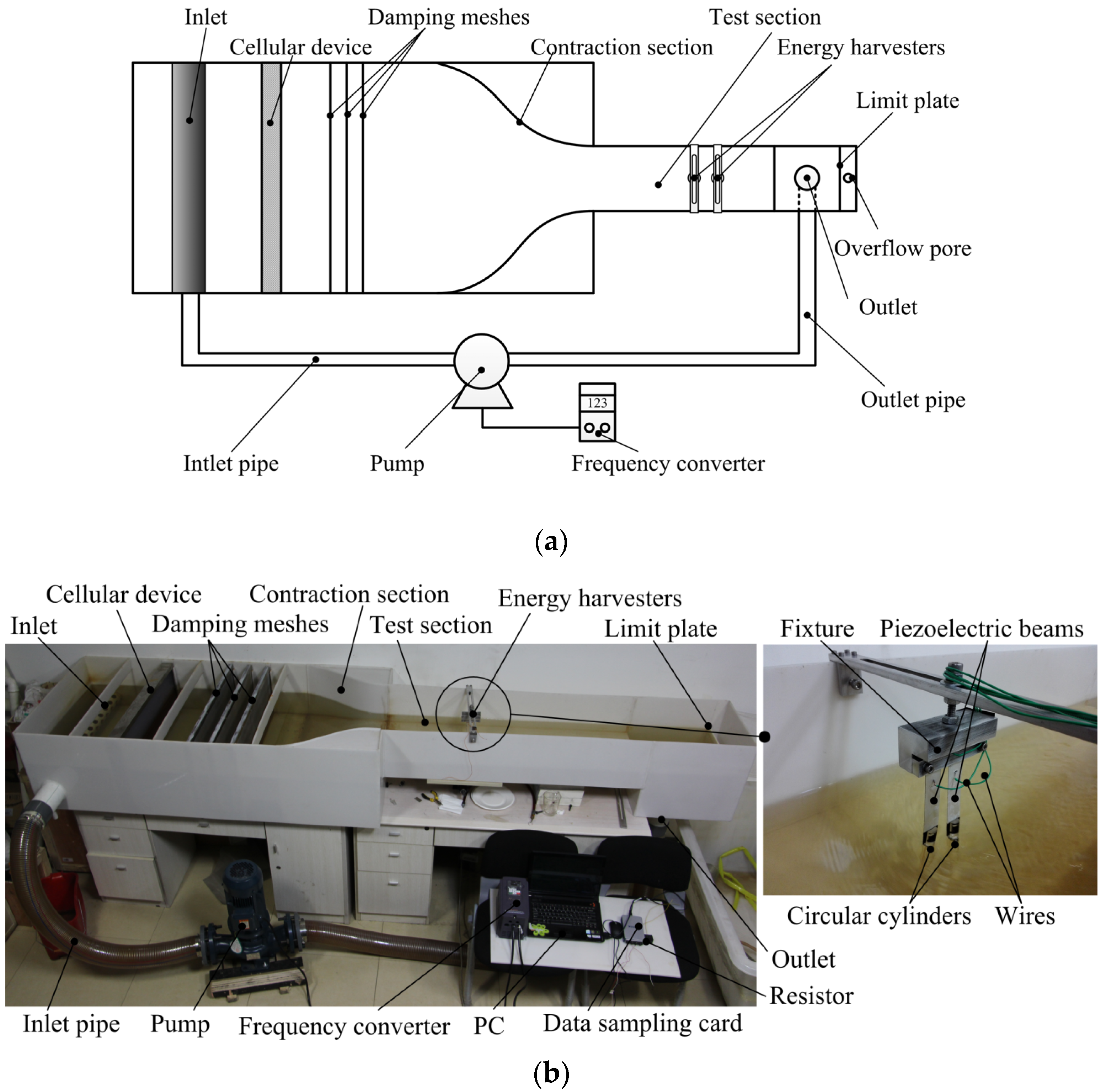
Figure 1a,b illustrate the schematic diagram and physical picture of the water channel platform, respectively. The experimental system is composed of five parts, including an open channel, a pump (Shimge Co., Ltd
®; Hangzhou, China), a frequency converter (Shenzhen Junhui Electronics Co., Ltd
®, Shenzhen, China), a cellular device (Qingdao Tonglide plastic buzzer hives Co., Ltd
®, Qingdao, China) and several damping meshes (Hangzhou Kuangshi Co., Ltd
®, Hangzhou, China). Water cycle in the experimental system with closed loop. Water is poured into the open channel from the inlet by the pump at a certain speed, which can be controlled, from 0 to 1 m/s, by changing the working frequency of the pump with the frequency converter. The water speed can be measured by the flow measuring instrument. The roles of cellular device and damping meshes are weakening the stream turbulence so as to provide a steady current for experiments. According to the experiences in the low speed wind tunnel design, the cellular device with small holes can effectively break vortex and smooth airflow if the angle between the free-stream flow and the hole axis is less than 10° and the length is 5–10 times more than the diameter of the hole. Furthermore, several damping meshes are always placed in the downstream of the cellular device to further break smaller vortex. In this paper, the holes of the cellular device are hexagon, and their equivalent diameter and length are Ф8 mm and 40 mm, respectively, and three damping meshes are used to weaken stream turbulence and provide a steady current. Furthermore, the contraction section is designed to increase the water speed and improve the quality of the flow flied. Finally, water steadily passes through the test section, runs into the outlet and pours into the open channel. There is a limit plate to ensure the depth of water.
Figure 2a shows the schematic of the two tandem identical piezoelectric energy harvesters system, and
Figure 2b shows the composition of the energy harvester, what is made up of a piezoelectric beam (Baoding Hengsheng Acoustics Electron Apparatus Co., Ltd
®, Baoding, Hebei, China) and a circular cylinder (Guangzhou Huaying Plexiglass Co., Ltd
®, Guangzhou, China). The piezoelectric beam has the advantages of simple construction, easy to produce, low cost, high energy density and low natural frequency. According to the theory of fluid dynamics, the fluid will exert a force on the object with non-streamlined boundary when the fluid flows through it. Hence the piezoelectric beam will oscillate caused by the circular cylinder whose most part is immersed in flowing water. Furthermore, adding the cylinders is mean to decrease the natural frequency. The harvesters in the paper are used at low water speed. The frequency of the vortex shedding from the cylinder is low. Hence the harvesters with low natural frequency are easy to resonate, and have larger power output. The circular cylinder of 12 mm (diameter,
D) × 80 mm (length) is vertically equipped at the end of the piezoelectric beam, which contains a substrate layer and a piezoelectric layer. The two layers of the beam are the same in size, 80 mm (active length) × 20 mm (wide) × 0.2 mm (thickness). The material of substrate layer is aluminum and that of piezoelectric layer is PZT-5H. Fixing the other end of the piezoelectric beam, putting the circular cylinder in flowing water, output voltage can be obtained across the resistor connected with the beam. The experiment data is entered into a computer using a data sampling card of NI corporation (National Instruments, Austin, TX, USA).
Table 1 lists the detailed material parameters of the energy harvester prototype.
Each of the two piezoelectric energy harvesters can be explained by a lumped-parameter model for the VIV-based energy harvesters, respectively. The governing equations are written as
where
x is the displacement of cylinder in the direction normal to the water flow (
U); (∙) means derivative with respect to the dimensional time t.
Meq is the equivalent mass of the harvester, which can be worked out based on simple beam theory and conservation of kinetic energy.
Meq takes into account both the mass of the structure and the fluid-added mass, which models viscid inertial effects.
K is the equivalent stiffness of the harvester, which can be worked out based on simple beam theory and Hooke’s law;
C is the damping coefficient of the harvester, which can be worked out based on a free vibration test. Θ,
Cp, and
V are the electromechanical coupling coefficient, the capacitance of the piezoelectric sheet, and the generated voltage, respectively;
R is the electrical load resistance.
FL is the vortex-induced force. Because of the interaction between the two tandem harvesters,
FL is especially complicated, and cannot be empirically established based on the previous wake oscillator model. Currently, the most useful methods for investigating the dynamic response and energy harvesting performances of the two coupled energy harvesters are numerical simulation and experimental test. Here, we choose the experimental method.
According to the parameters in
Table 1, the values of
Meq and
K are 0.0154 kg and 9.366 N/m, respectively. Hence, the natural frequency
fn is 3.92 Hz worked out by
Meq and
K. The Damping ratio is 0.038. Furthermore, the frequency of the vortex shedding from the cylinder is calculated as follows
where
U is the water speed,
D is the diameters of the cylinder, and
St is the Strouhal number. When
fs is around
fn, the harvester will resonate. Hence, the harvester can be designed with a right
fn targeting an intended flow rate.
3. Results and Discussion
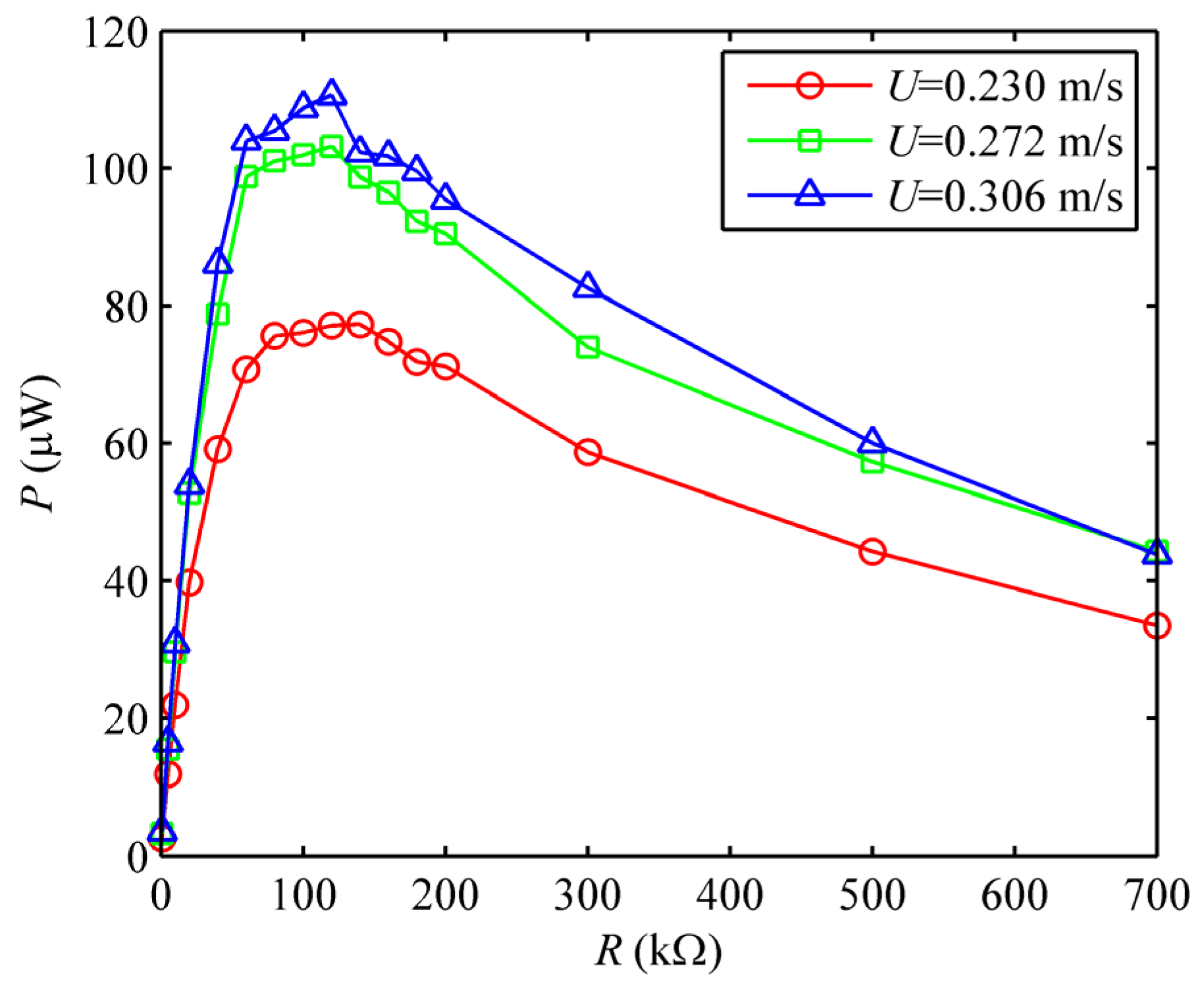
Firstly, we place only one harvester in the test section of the water channel to investigate its performance. The corresponding result is used to choose the optimal resistance and compare it to the performances of the two tandem harvesters in the following section. The plotted curves in
Figure 3 show variations of the output power with different load resistances at three water speeds, namely
U = 0.230 m/s,
U = 0.272 m/s,
U = 0.306 m/s. Clearly, the output power first increases and then decreases with the load resistance increasing. In other words, there is an optimal resistance at which the output power is at its maximum. In this case, the optimal resistances are around 100 kΩ at all of the water speeds.
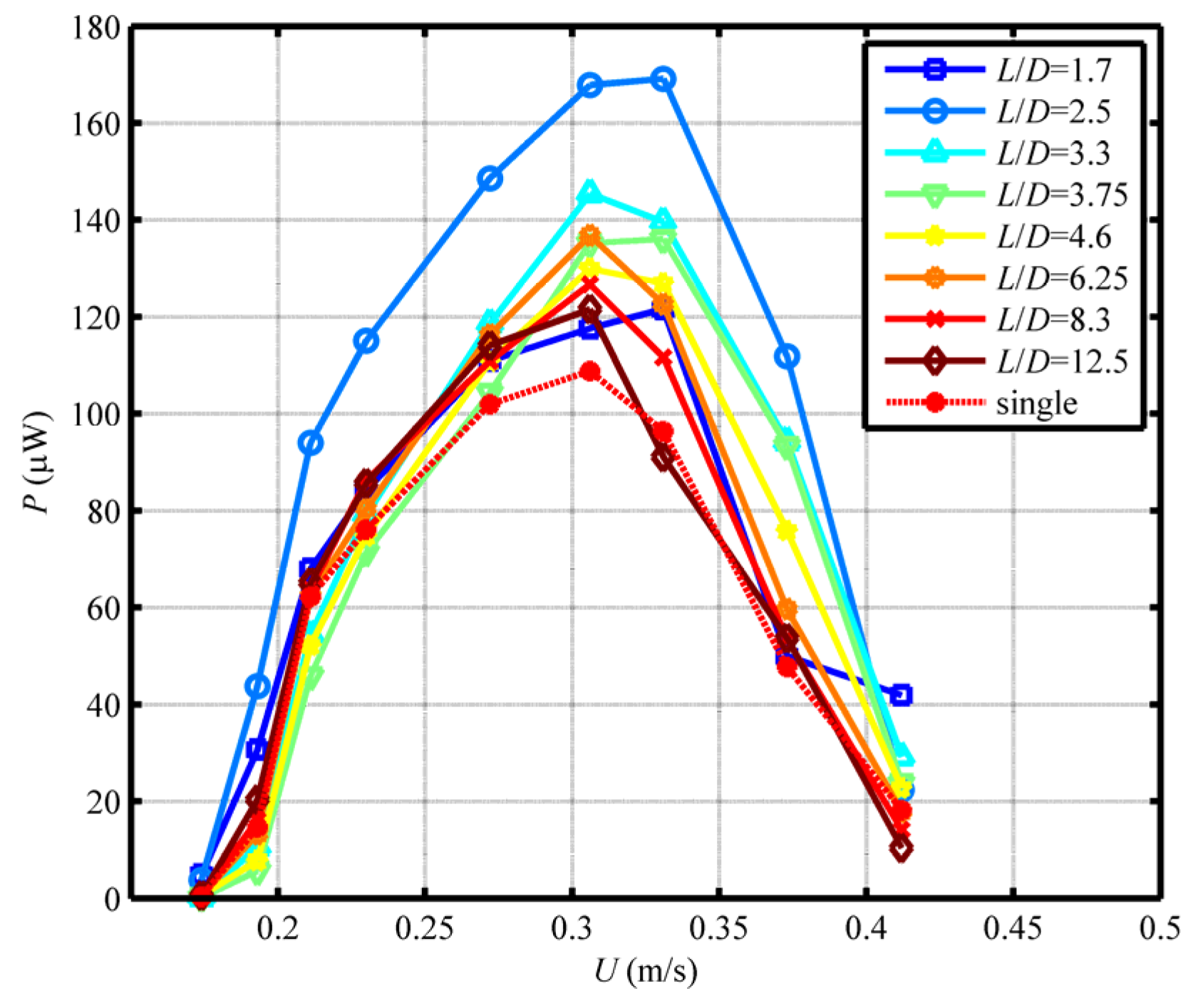
Then, two harvesters with identical geometry are placed in the test section of the water channel to investigate their energy-harvesting performances. The two harvesters are arranged in a tandem array, as shown in
Figure 2a. By setting the electrical load resistance at a constant value of 100 kΩ, and varying the spacing ratio (
L/
D) between the two tandem harvesters from 1.7 to 12.5 and the water speed from 0.1 m/s to 0.5 m/s, different dynamic responses are found in the two harvesters.
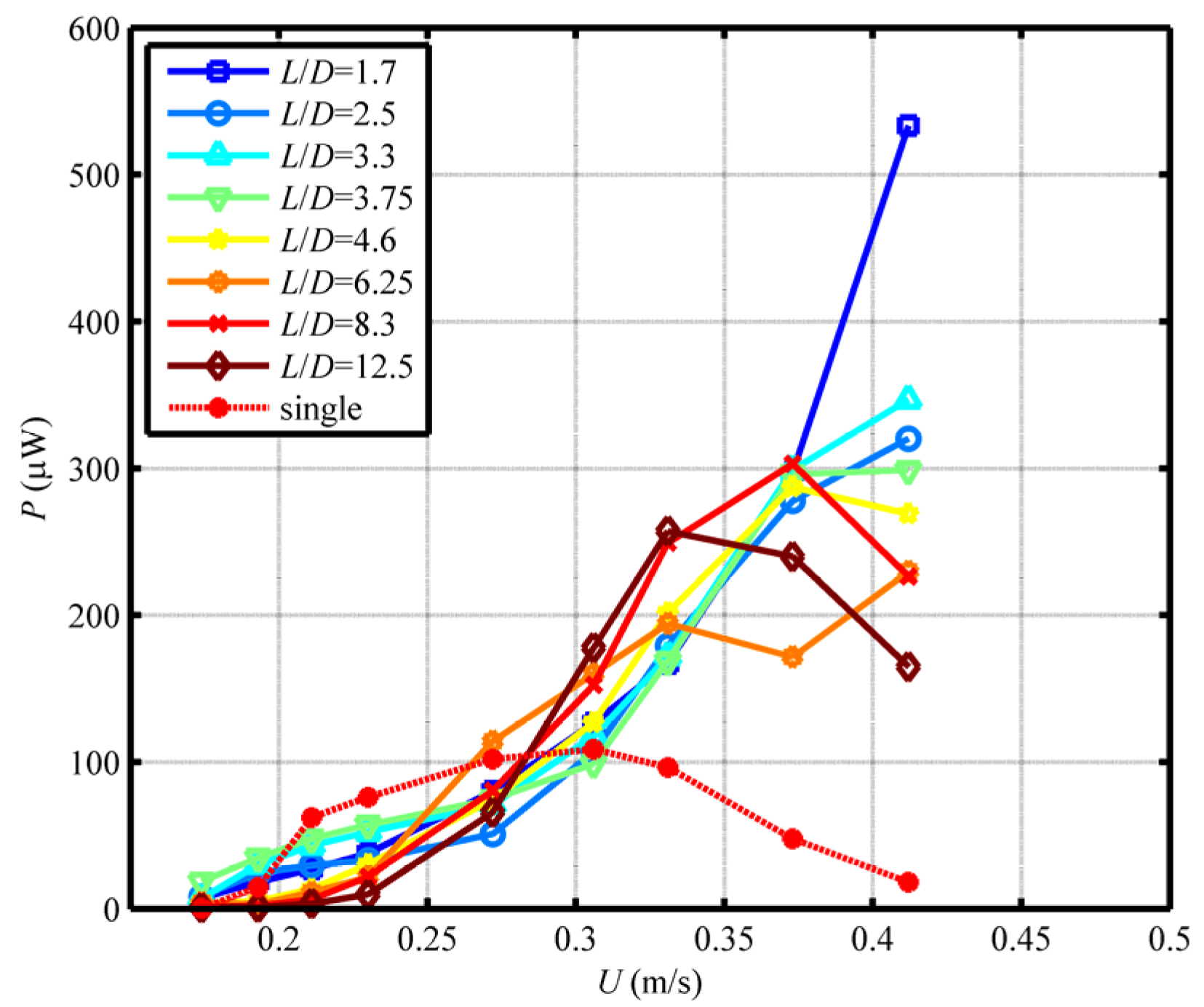
Figure 4 shows the relationship between the output powers of the two tandem harvesters and the water speed in the case of eight spacing ratios namely,
L/
D = 1.7, 2.5, 3.3, 3.75, 4.6, 6.25, 8.3 and 12.5.
From
Figure 4, on the one hand, it is easy to find that, with the water speed increasing, the changing trends of the output power of the upstream harvester are similar for all the spacing ratios. The trends of the output power are increased at first and then decreased. The dynamic response of the upstream harvester is vortex-induced vibration. On the other hand, the performance of the downstream harvester is totally different from that of the upstream harvester. The output power of the downstream harvester only increases with the water speed increasing for the spacing ratio
L/
D < 6.25. The dynamic response of the downstream harvester is wake-induced vibration which is a divergent oscillation. It is because the downstream harvester is in the wake flow field and is influenced by the vortex shedding from the upstream harvester. However, the effect of the upstream harvester on the downstream one is being impaired with the spacing ratio expanding and it eventually disappears. Hence, we conclude that the performance of the upstream harvester has been less affected by the downstream one, but it is the very opposite of the downstream one in that the performance of the downstream harvester strongly depends on the upstream one. We also find that the sum of the output power of the two tandem harvesters is more than double that of a single harvester, even much more in some cases. It shows that the interactions between the two tandem harvesters have some effect on their performances.
Therefore, in order to further investigate the energy-harvesting performance of each harvester, we respectively analyze them and compare their own performances to the single harvester (without an upstream or downstream harvester) in two ways: one is by fixing the spacing ratio and varying the water speed, the other one is by fixing the water speed and varying the spacing ratio.
3.1. Energy-Harvesting Performance of The Upstream Harvester
Figure 5a shows the effect of the water speed on the output power when the resistance is a constant at
R = 100 kΩ, and the spacing ratio
L/
D = 3.3. It can be found that the output power strongly depends on the water speed. In the low water speed range (
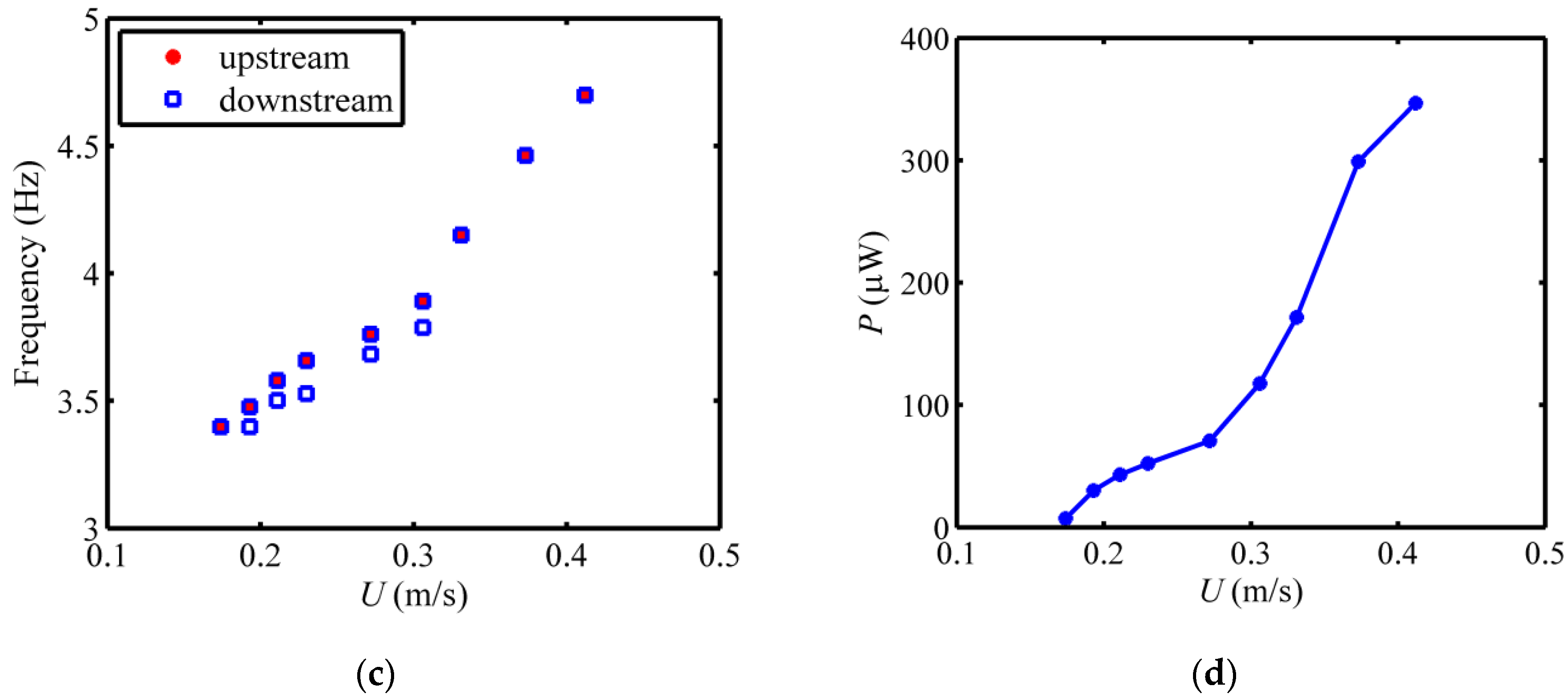
U ≤ 0.193 m/s), the output power of the upstream harvester is relatively small. This value increases significantly in the middle range of the water speed values and yields a peak for the output power when the water speed is 0.306 m/s. In the higher water speed range, the output power drops again to values that are close to those obtained in the low water speed range. When the value of the water speed is 0.306 m/s, the time history of the output voltage of the upstream harvester and its Fast Fourier Transform (FFT) analysis are shown in
Figure 5b,c. It notes that the output voltage can be regarded as a simple harmonic wave with a frequency of 3.891 Hz. On the other hand, the output voltage is generated because of the oscillation of the cylindrical vibrator, which is stimulated by the vortex shedding from the cylinder. So the frequency of the vortex shedding from the cylinder equals that of the output voltage, 3.891 Hz. This frequency is very close to the natural frequency of the harvester, 3.92 Hz. As a result, the harvester resonates at the water speed of 0.306 m/s. That is the reason why the output power reaches a peak.
Figure 6 shows the output powers of the upstream harvester and the single harvester as a function of the water speed for eight different spacing ratios. It notes that, with the water speed increasing, the changing trend of the output power of the upstream harvester is similar to the single harvester for specific spacing ratios. In other words, the downstream harvester has no effect on the vibration form (vortex-induced vibration) of the upstream harvester. However, the performance of the upstream harvester is different from that of the single harvester. This is because the wake flow field of the upstream harvester is changed by the vibration of the downstream harvester. The changing of the performance varies with the value of the water speed. In the lower and higher water speed range (
U ≤ 0.230 m/s,
U ≥ 0.412 m/s), the output power is nearly equal to that of the single harvester. In the middle range of the water speed, however, the output power is greater than that of the single harvester. In addition, the enhancement of the performance is related to the spacing ratio for a specific water speed. In a low spacing ratio range, the performance of the upstream harvester is significantly enhanced compared to that of the single harvester. Particularly, the output power is the largest when the spacing ratio is near
L/
D = 2.5. With the spacing ratio increasing, the enhancement of the performance is weakened. Finally, the output power of the upstream harvester is close to that of the single harvester and stabilizes. This is because the vortex shedding from the upstream harvester will directly attach to the downstream harvester when the space between the two harvesters is smaller than the size of the vortex. The movement of the downstream harvester will block the vortex and increase the stream turbulence. The speed difference between the two sides of the upstream harvester and the force becomes greater than that of the single harvester. As a result, the upstream harvester has a larger power output. With the increase of the spacing ratio, the effect of the downstream harvester on the vortex shedding from the upstream harvester becomes smaller, and the output power of the upstream harvester is close to that of the single harvester. The results indicate that the wake flow field can be divided into two cases based on the value of the spacing ratio: the near wake flow field and far wake flow field. If the downstream harvester is placed in the near wake flow field, it plays a positive role in enhancing the performance of the upstream harvester; otherwise, the effect disappears.
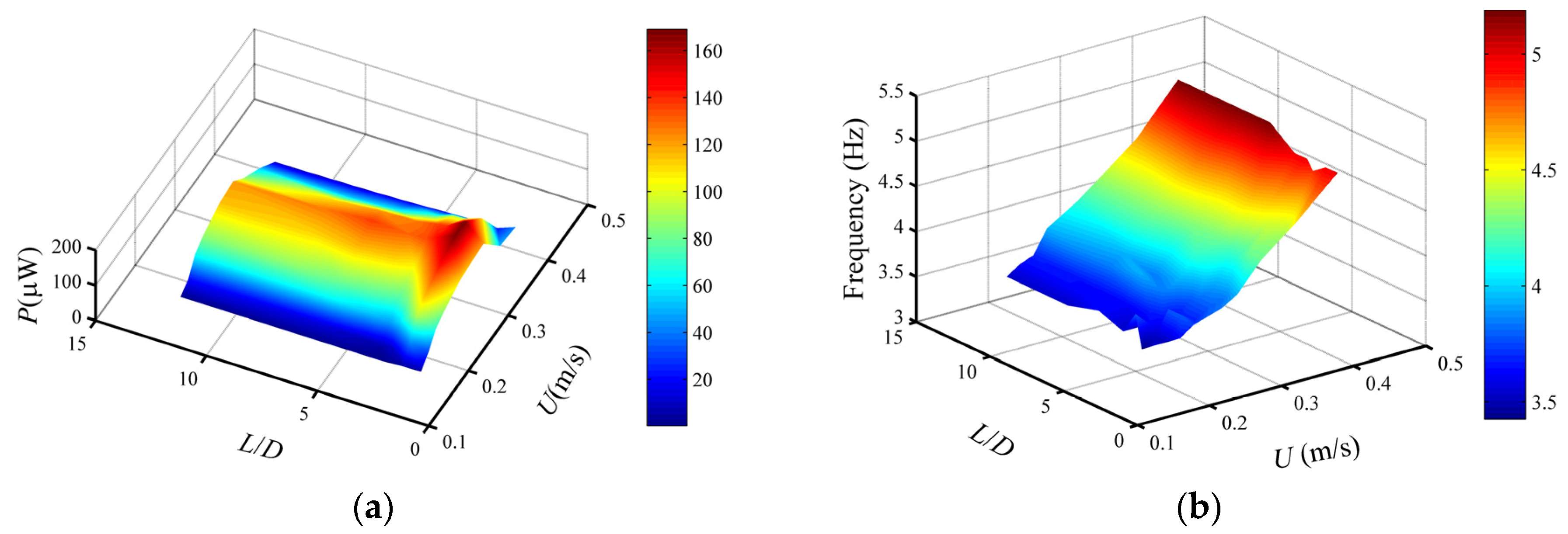
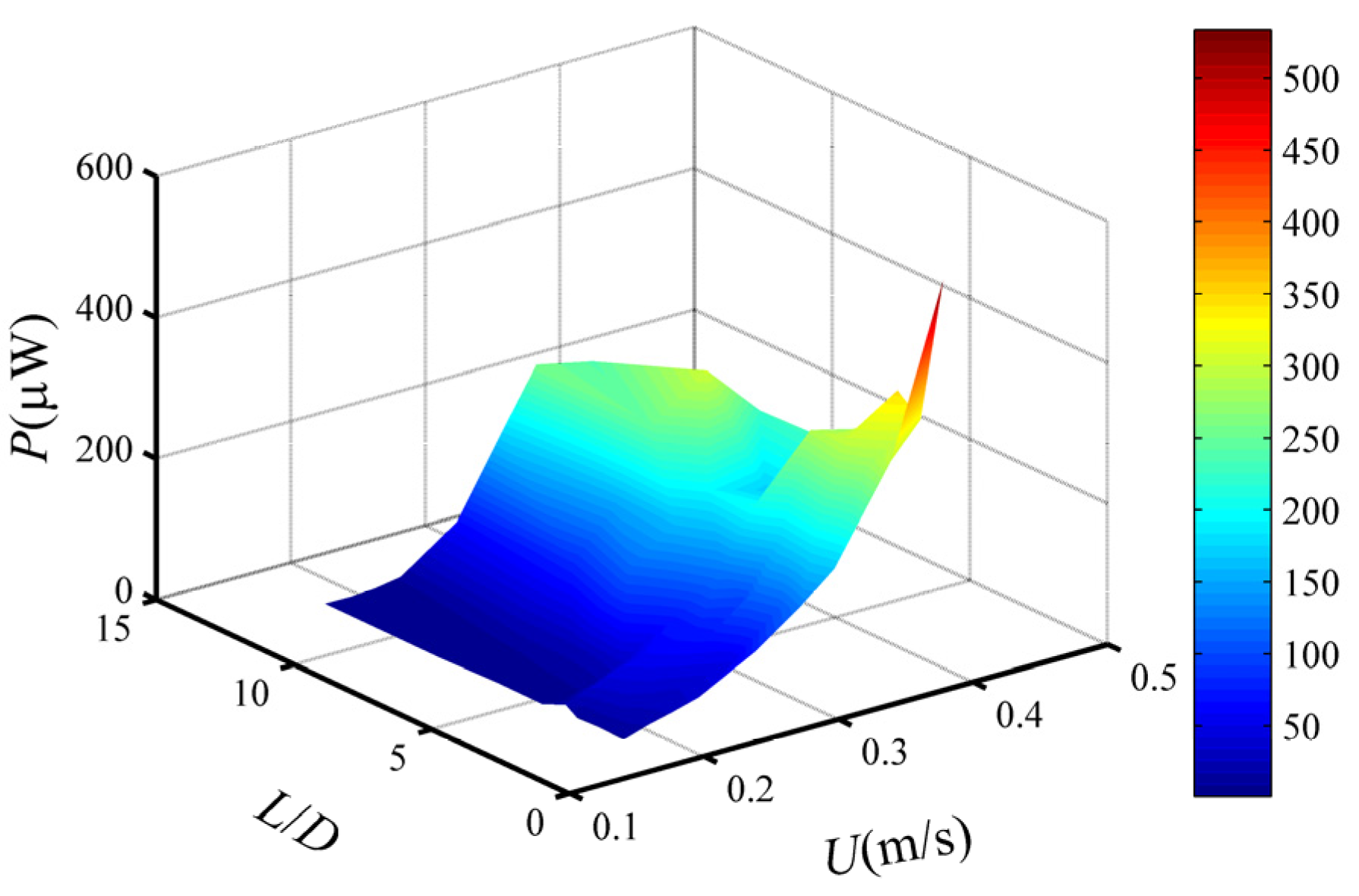
Figure 7a,b show the variations of the output power and vortex shedding frequency with the water speed and the spacing ratio, respectively.
Figure 7a illustrates that the gradient of the output power is very large along the spacing ratio direction in the low spacing ratio range (
L/
D ≤ 3.75); that is, the spacing ratio has a great effect on the performance of the upstream harvester. While in a larger spacing ratio range, the effect of the spacing ratio becomes weak because the gradient of the output power is approximately equal to zero along the spacing ratio direction. On the other hand, the water speed always has a great effect on the performance of the upstream harvester because the gradient of the output power is always very great along the water speed direction.
Figure 7b illustrates that increasing the water speed results in an increase in the vortex shedding frequency for a specific spacing ratio. With the spacing ratio increasing, however, the vortex shedding frequency remains roughly stable for a specific water speed. It can be concluded that the vortex shedding frequency depends on the water speed rather the spacing ratio.
3.2. Energy-Harvesting Performance of The Downstream Harvester
The downstream harvester is placed in the wake flow field of the upstream harvester. The characteristics of the flow field around the downstream harvester are different from that of the single harvester. As a result, their dynamic responses and performances are different.
Figure 8a shows the time history of the output voltage of the downstream harvester when the spacing ratio is
L/
D = 3.3, and water speed is
U = 0.306 m/s. From
Figure 8a, we find that the beat vibration happens in the downstream harvester. It can be concluded that the output voltage signal of the downstream harvester comprises several simple harmonic components with similar frequencies.
Figure 8b shows the FFT analysis result of the output voltage.
Figure 8a shows that the output voltage comprises mainly two simple harmonic components with the frequencies of 3.787 Hz and 3.891 Hz. Furthermore, we compare the frequency of the output voltages of the downstream harvester to that of the upstream harvester at different water speeds in
Figure 8c. We find that the frequencies of the output voltages of the downstream harvester contain or are equal to that of the upstream harvester. This is because the vortex shedding from the upstream harvester exerts a force, whose frequency equals that of the output voltage of the upstream harvester, on the downstream harvester.
Figure 8d shows the variations of the output power of the downstream harvester with different water speeds. Inspecting this figure, we find that increasing the water speed always results in an increase in the output power of the downstream harvester. It is different from the upstream harvester. In the low water speed range (
U ≤ 0.272 m/s), the increasing of the output power with the water speed is relatively small. However, this variation increases significantly in the higher water speed range.
Figure 9 shows the output powers of the downstream harvester and the single harvester as a function of the water speed for eight different spacing ratios. We find that the performance of the downstream harvester is totally different from that of the single harvester for a specific spacing ratio. When the water speed is
U < 0.306 m/s, the increase of the output power with the water speed is relatively slow compared to the single harvester and, therefore, the performance of the downstream is weaker than that of the single harvester. With the water speed continuing to increase, this increase becomes significantly faster, but the performance of the single harvester then declines. As a result, the performance of the downstream harvester becomes better than that of the single harvester. We conclude that the upstream harvester has dual effects on the performance of the downstream harvester: in the low water speed range, the performance of the downstream harvester is weakened compared to the single harvester, while in the higher water speed range, the performance is enhanced, conversely. Furthermore, with the spacing ratio increasing, the performance of the downstream harvester will decrease in the higher water speed range. Finally, the performance of the downstream harvester will be equal to that of the single harvester if the spacing ratio is big enough.
To further investigate the impacts of the water speed and the spacing ratio on the performance of the downstream harvester, the variations of the output power with the water speed and the spacing ratio are illuminated in
Figure 10. It can be found that, on the one hand, the effect of the spacing ratio on the performance of the downstream harvester is negligible in the low water speed range, but remarkable in the high water speed range. On the other hand, no matter how the spacing ratio changes, the effect of the water speed on the output power is always there.
4. Conclusions
This work explores the energy-harvesting performances of two tandem identical piezoelectric energy harvesters with cylinders in the water flow. The experimental results show that the performance of the upstream harvester is totally different from that of the downstream harvester. For the upstream harvester, given a specific spacing ratio, there is always an optimal water speed at which the maximum output power can be obtained. Furthermore, the maximum output power is relevant to the spacing ratio. According to the experimental results, the optimal performance (167.8 μW) of the upstream harvester can be obtained at the water speed of 0.306 m/s and the spacing ratio of 2.5. Compared to the single harvester, the performance of the upstream harvester is enhanced when the water speed is around the optimal value. With the spacing ratio increasing, the enhancement is weakened or even disappears. For the downstream harvester, the performance is totally changed because of the effect of the vortex shedding from the upstream harvester. The output power increases with the water speed increasing. Compared to the single harvester, the performance of the downstream harvester is weakened in the low water speed range. However, the performance would be significantly enhanced in the higher water speed. The output power of the downstream harvester (533.2 μW) is 29 times more than that of the single harvester at the water speed of 0.412 m/s and the spacing ratio of 1.7. With the spacing ratio increasing, the enhancement is weakened or even disappears as well.
This study indicates that the energy-harvesting performances of the two tandem harvesters can be enhanced by appropriately matching the water speed and spacing ratio. It provides a basis to generate more energy by using a group of energy harvesters in the water flow.


