
Generating Radially and Azimuthally Polarized Beams by Using a Pair of Lateral Displacement Beamsplitters


Abstract
:
1. Introduction
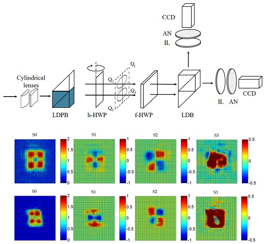
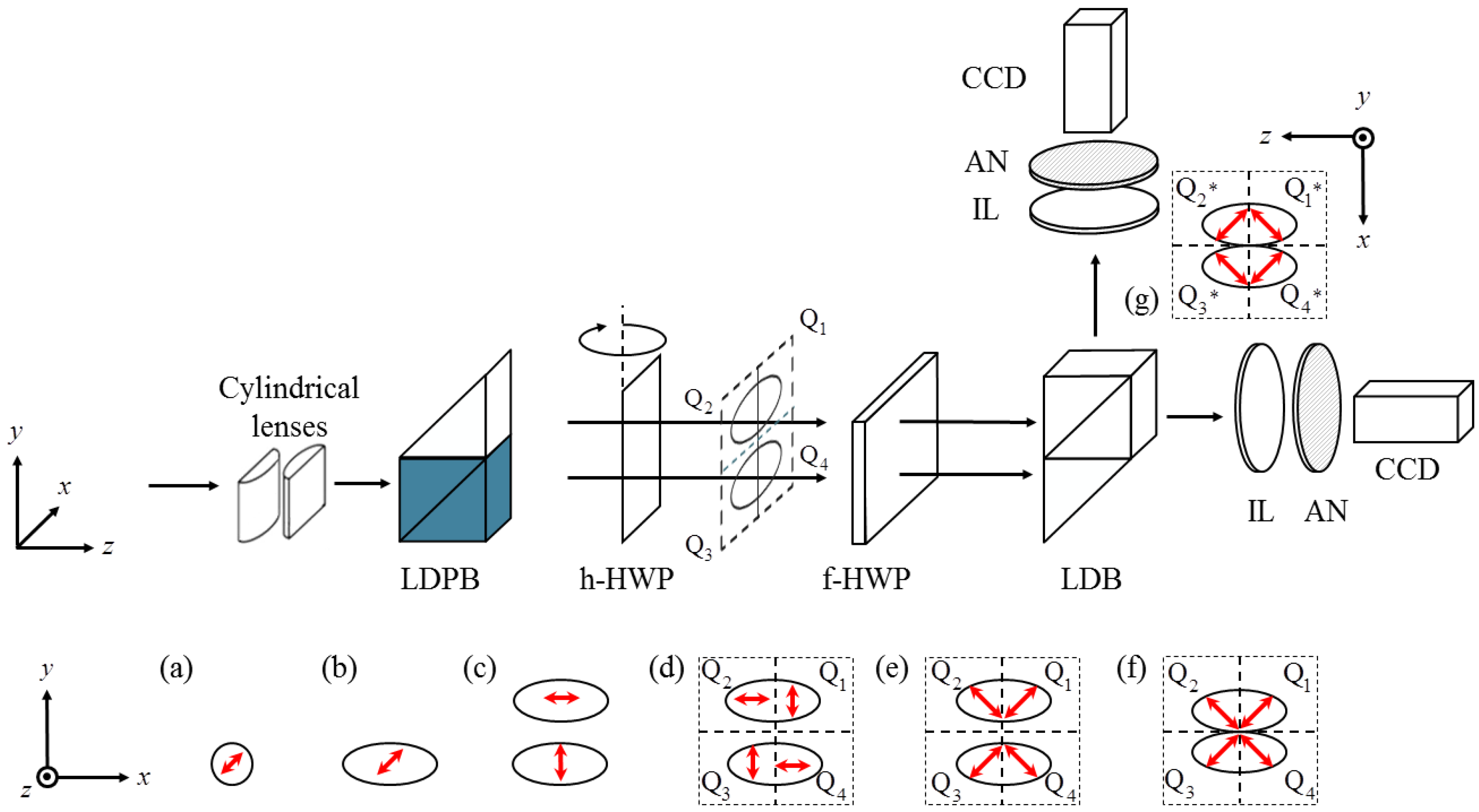
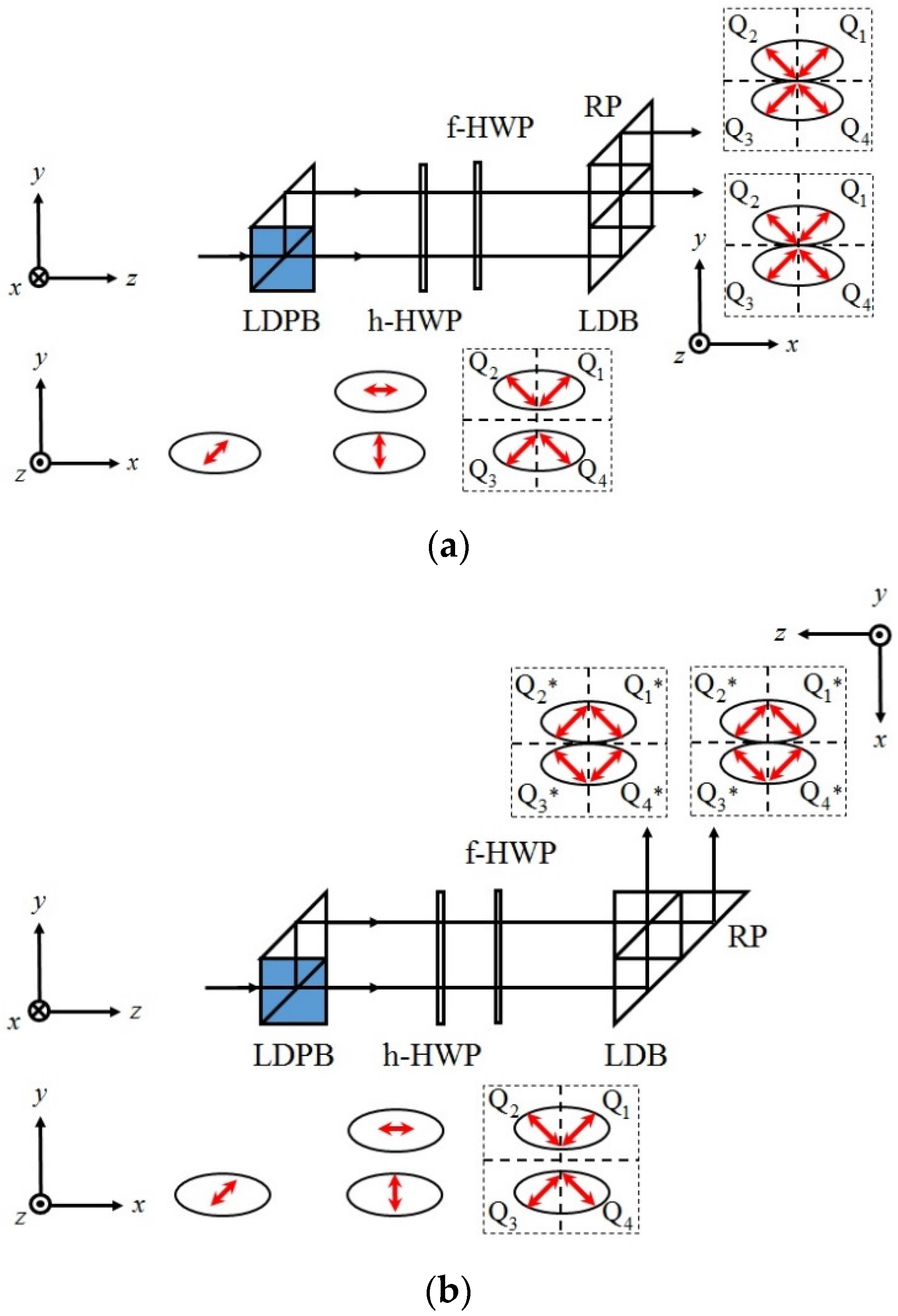
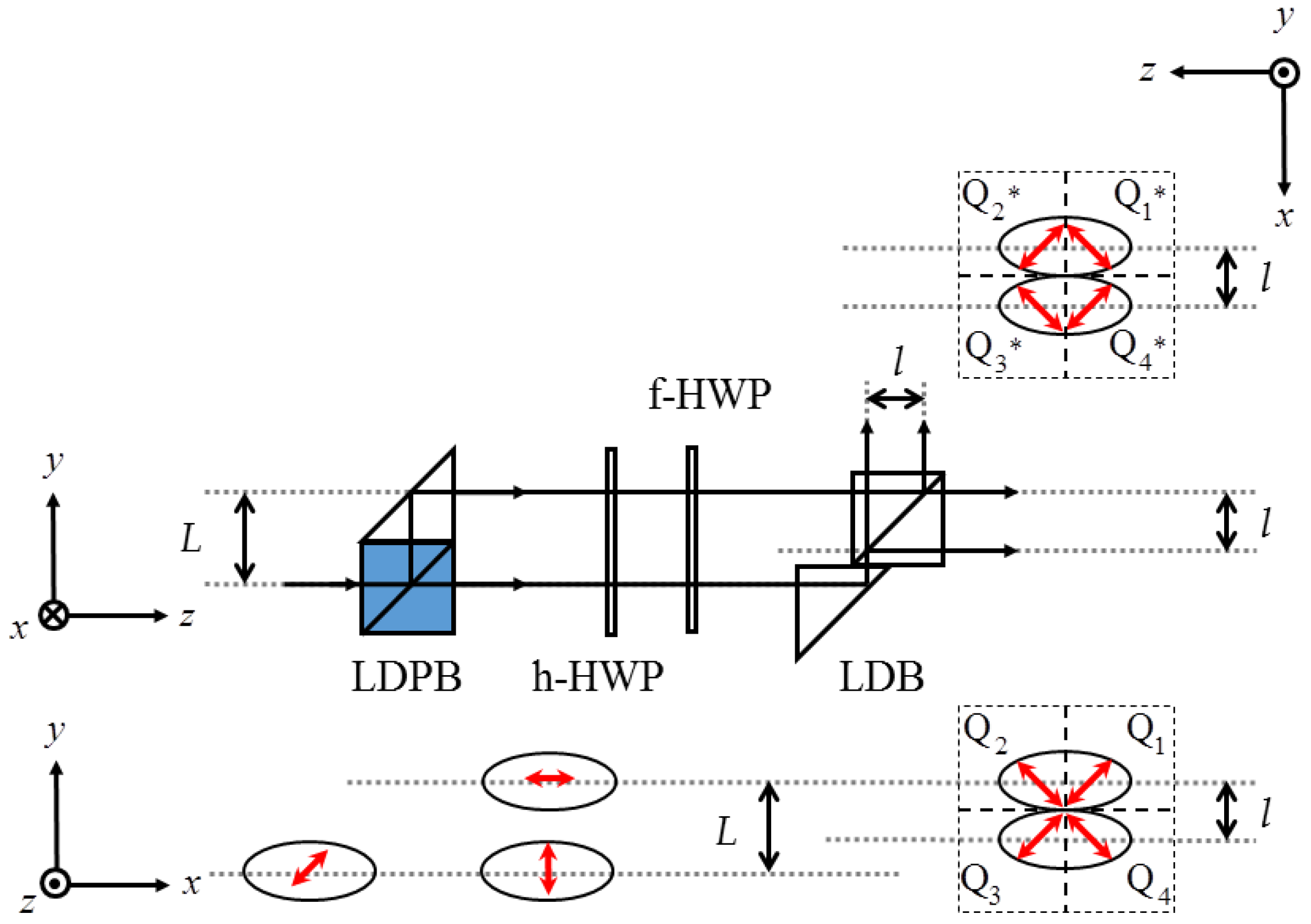
2. Principles
3. Results and Discussion
4. Conclusions
Acknowledgments
Author Contributions
Conflicts of Interest
References
- Dorn, R.; Quabis, S.; Lcuchs, G. Sharper focus for a radially polarized light beam. Phys. Rev. Lett. 2003, 91. [Google Scholar] [CrossRef] [PubMed]
- Passilly, N.; de Saint Denis, R.; Aït-Ameur, K.; Treussart, F.; Hierle, R.; Roch, J.F. Simple interferometric technique for generation of a radially polarized light beam. J. Opt. Soc. Am. A 2005, 22, 984–991. [Google Scholar] [CrossRef]
- Zhan, Q. Cylindrical vector beams: From mathematical concepts to applications. Adv. Opt. Photonics 2009, 1, 1–57. [Google Scholar] [CrossRef]
- Niziev, V.G.; Nesterov, A.V. Influence of beam polarization on laser cutting efficiency. J. Phys. D Appl. Phys. 1999, 32, 1455–1461. [Google Scholar] [CrossRef]
- Peng, F.; Yao, B.; Yan, S.; Zhao, W.; Lei, M. Trapping of low-refractive-index particles with azimuthally polarized beam. J. Opt. Soc. Am. B 2009, 26, 2242–2247. [Google Scholar] [CrossRef]
- Zhang, Y.; Bai, J. Improving the recording ability of a near-field optical storage system by higher-order radially polarized beams. Opt. Express 2009, 17, 3698–3706. [Google Scholar] [CrossRef] [PubMed]
- Li, J.L.; Ueda, K.I.; Musha, M.; Shirakawa, A.; Zhong, L.X. Generation of radially polarized mode in Yb fiber laser by using a dual conical prism. Opt. Lett. 2006, 31, 2969–2971. [Google Scholar] [CrossRef] [PubMed]
- Bomzon, Z.; Kleiner, V.; Hasman, E. Formation of radially and azimuthally polarized light using space-variant subwavelength metal stripe gratings. Appl. Phys. Lett. 2001, 79, 1587–1589. [Google Scholar] [CrossRef]
- Machavariani, G.; Lumer, Y.; Moshe, I.; Meir, A.; Jackel, S. Efficient extracavity generation of radially and azimuthally polarized beams. Opt. Lett. 2007, 32, 1468–1470. [Google Scholar] [CrossRef] [PubMed]
- Bashkansky, M.; Park, D.; Fatemi, F.K. Azimuthally and radially polarized light with a nematic SLM. Opt. Express 2010, 18, 212–217. [Google Scholar] [CrossRef] [PubMed]
- Radwell, N.; Hawley, R.D.; Götte, J.B.; Franke-Arnold, S. Achromatic vector vortex beams from a glass cone. Nat. Commun. 2016, 7, 1–6. [Google Scholar] [CrossRef] [PubMed]
- Han, C.-Y.; Chang, R.-S.; Chen, H.-F. Solid-state interferometry of a pentaprism for generating cylindrical vector beam. Opt. Rev. 2013, 20, 189–192. [Google Scholar] [CrossRef]
- Phua, P.B.; Lai, W.J. Simple coherent polarization manipulation scheme for generating high power radially polarized beam. Opt. Express 2007, 15, 14251–14256. [Google Scholar] [CrossRef] [PubMed]
- Collett, E. Field Guide to Polarization, 3rd ed.; SPIE-The International Society for Optical Engineering: Bellingham, WA, USA, 2005; pp. 57–62. [Google Scholar]
- Kogelnik, H.; Li, T. Laser beams and resonators. Appl. Opt. 1996, 5, 1550–1567. [Google Scholar] [CrossRef] [PubMed]
- Chen, J.-H.; Chang, R.-S.; Han, C.-Y. Generating a cylindrical vector beam interferometrically for ellipsometric measurement. Opt. Commun. 2016, 361, 116–123. [Google Scholar] [CrossRef]


© 2016 by the authors; licensee MDPI, Basel, Switzerland. This article is an open access article distributed under the terms and conditions of the Creative Commons Attribution (CC-BY) license (http://creativecommons.org/licenses/by/4.0/).
Share and Cite
Han, C.-Y.; Wei, Z.-H.; Hsu, Y.; Chen, K.-H.; Yeh, C.-H.; Wu, W.-X.; Chen, J.-H. Generating Radially and Azimuthally Polarized Beams by Using a Pair of Lateral Displacement Beamsplitters. Appl. Sci. 2016, 6, 241. https://doi.org/10.3390/app6090241
Han C-Y, Wei Z-H, Hsu Y, Chen K-H, Yeh C-H, Wu W-X, Chen J-H. Generating Radially and Azimuthally Polarized Beams by Using a Pair of Lateral Displacement Beamsplitters. Applied Sciences. 2016; 6(9):241. https://doi.org/10.3390/app6090241
Chicago/Turabian StyleHan, Chien-Yuan, Zhi-Hao Wei, Yung Hsu, Kun-Huang Chen, Chien-Hung Yeh, Wei-Xuan Wu, and Jing-Heng Chen. 2016. "Generating Radially and Azimuthally Polarized Beams by Using a Pair of Lateral Displacement Beamsplitters" Applied Sciences 6, no. 9: 241. https://doi.org/10.3390/app6090241