The Effect of Magnetic Field on Thermal-Reaction Kinetics of a Paramagnetic Metal Hydride Storage Bed


1
National Center for Hydrogen Research, Florida Institute of Technology, Melbourne, FL 32901, USA
2
Department of Mechanical and Aerospace Engineering, New Mexico State University, Las Cruces, NM 88003, USA
*
Author to whom correspondence should be addressed.
Appl. Sci. 2017, 7(10), 1006; https://doi.org/10.3390/app7101006
Submission received: 4 August 2017
/
Accepted: 7 September 2017
/
Published: 29 September 2017
(This article belongs to the Special Issue Clean Energy and Fuel (Hydrogen) Storage)
Abstract
:Featured Application
The results of this research are applicable to metal hydride hydrogen storage systems and the onboard hydrogen storage system in the automobile industry.
Abstract
A safe and efficient method for storing hydrogen is solid state storage through a chemical reaction in metal hydrides. A good amount of research has been conducted on hydrogenation properties of metal hydrides and possible methods to improve them. Background research shows that heat transfer is one of the reaction rate controlling parameters in a metal hydride hydrogen storage system. Considering that some very well-known hydrides like lanthanum nickel (LaNi5) and magnesium hydride (MgH2) are paramagnetic materials, the effect of an external magnetic field on heat conduction and reaction kinetics in a metal hydride storage system with such materials needs to be studied. In the current paper, hydrogenation properties of lanthanum nickel under magnetism were studied. The properties which were under consideration include reaction kinetics, hydrogen absorption capacity, and hydrogenation time. Experimentation has proven the positive effect of applying magnetic fields on the heat conduction, reaction kinetics, and hydrogenation time of a lanthanum nickel bed. However, magnetism did not increase the hydrogenation capacity of lanthanum nickel, which is evidence to prove that elevated hydrogenation characteristics result from enhanced heat transfer in the bed.
1. Introduction
Metal hydrides are materials which can chemically react with hydrogen to form a compound including hydrogen and at least one metal. A well-known group of metal hydrides are intermetallic compounds which are obtained by combining a stable-hydride-forming element and an unstable-hydride-forming element. They demonstrate good hydrogen storage properties in low pressures, while their volumetric densities are comparable with liquid hydrogen. Research on applications of metal hydrides has been in process for many years and includes investigating simple metal hydrides, such as magnesium hydride, and metal-hydride alloys, such as titanium-iron hydride.
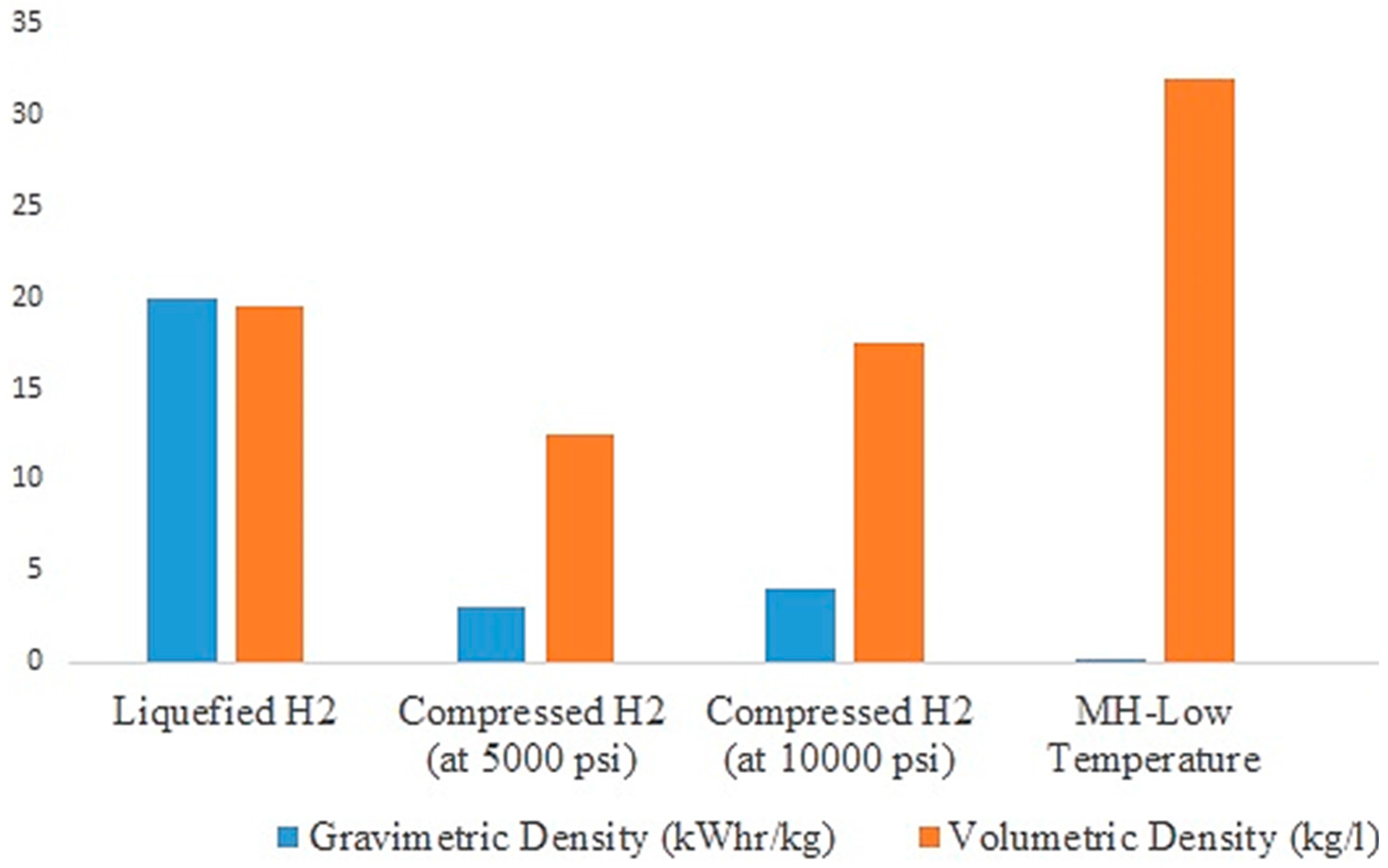
A useful property of metal hydrides is their ability to absorb and desorb hydrogen at a constant pressure [1]. They also offer the advantage of hydrogen storage under moderate temperatures while safely performing as high volume efficient storage [2]. Another advantage of metal hydrides is that they can be used to store hydrogen and heat simultaneously. Their gravimetric and volumetric energy density is usually higher than other means of energy storage like Li-ion batteries while energy is stored at ambient temperature [3]. Metal hydride storage systems (like storage in LaNi5, for instance) usually have higher volumetric efficiency as compared to compressed gas technology, which is due to their near ambient operational pressures. A comparison of different hydrogen storage technologies is presented in Figure 1.
The performance of a metal hydride system depends on the properties of the selected metal hydride. Some of the desired properties for a metal hydride are: highly specific gravimetric energy density, compact in design, long life and low performance degradation, and, of course, being economical. For a storage system, properties such as high hydrogen absorption capacity, high thermal conductivity, fast reaction kinetics, favorable equilibrium pressure, a simple activation process, and minimum degradation after cyclic operation are desired as well [4,5,6,7,8]. Some of the hydrogen release reaction characteristics are its thermochemistry, kinetics, phase changes, reagent requirements, catalyst morphology and amount, and species and levels of gaseous byproducts relative to hydrogen [9,10,11,12].
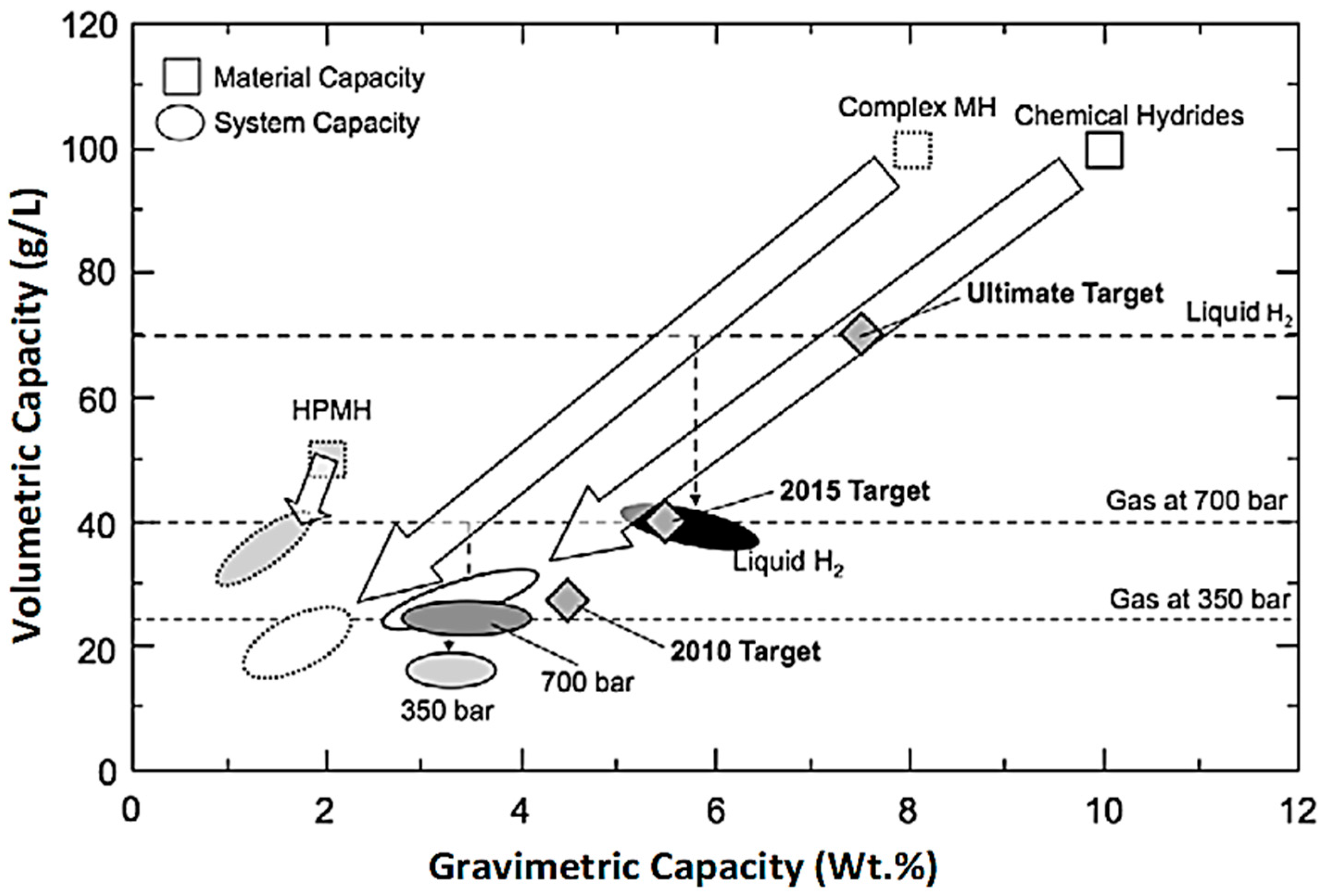
Metal hydrides can be categorized into different types including AB5 (LaNi5), AB2 (ZrV2), AB (FeTi), and A2B (Mg2Ni) based on their chemical composition. Among all these types, AB2 and AB5 are the best known metal hydrides to absorb hydrogen. The AB2 family of metal hydrides have an excellent hydrogen capacity (up to over 7 wt %) but have unacceptably slow kinetics of hydrogenation and dehydrogenation, even after extensive activation at 673 K (400 °C). The AB5 group has an excellent hydrogenation performance at ambient temperatures but poor hydrogen capacity typically in the range of 1–1.5 wt % [13]. Metal hydrides useful for on-board hydrogen storage and can be broadly categorized as: (1) complex metal hydrides (e.g., NaAlH4) that have low hydriding pressures (20–150 bar), relatively high hydriding temperatures (200–300 °C), and high volumetric capacities; and (2) high pressure metal hydrides (HPMH) that have high hydriding pressures and hydriding temperatures lower than 100 °C but have a low volumetric capacity (2–3 wt %) [14,15,16]. Both these types of metal hydrides require additional mechanisms such as external cooling, high pressure cylinders, etc., that increase the overall system weight and hence the reduced system capacity. In addition, carbon-based physisorption materials such as CNTs and MOFs show very high material storage capacities at low temperatures (77 K and 50–100 bar), and their hydrogen absorption capacity greatly decreases with an increase in temperatures [17,18]. Figure 2 shows the shows volumetric and gravimetric capacities of various storage materials and compares them to the best-known system capacities using these materials.
In practical applications, the rate of the hydrogen absorption/desorption reaction is often limited by how quickly heat can be added to, or removed from, the hydride as opposed to the intrinsic kinetics of hydriding and dehydriding [1,19]. While metal hydrides are basically alloys with good thermal conductivity, they break down into micron size particles after a few hydrogenation/dehydrogenation cycles in a hydrogen system. As a result, thermal conductivity is greatly affected and decreases significantly; typically, the thermal conductivity is around 1 W/(m·K) for metal hydrides [20,21]. In addition, when hydrogen is introduced into a hydride bed, its atoms fill the pores in the bed and result in even lower conduction rates. The decreased rate of heat transfer in a bed will eventually result in extended hydriding times [14]. Figure 3 shows the effect of the thermal conductivity of the bed on its fill time. It can be observed that for the typical thermal conductivity of metal hydrides, i.e., 1 W/(m·K), the fill time is significantly higher and can be reduced if the thermal conductivity can be at least doubled.
It is very important that the heat transfer is efficient in order for the hydriding reaction to proceed at a given pressure, and it can be achieved by using proper techniques for enhancing the thermal conductivity of the storage system. Enhancing heat conductivity is more a technical issue than a theoretical one, and measures have been presented experimentally to address this problem. Most of the methods are developed by adding solid matrices like fins or by compacting metal hydrides [22]. Some of these techniques are: using porous tubes/sheets for instantaneous hydrogen supply along the bed, porous bodies encapsulating the hydride powder, e.g., graphite structures, Porous Metal Hydride (PMH-compacts), metal-coated hydride particles, and the insertion of heat transfer enhancement matrices, e.g., metal screens and bands, metal foams, radial and axial metallic fins, and metallic wire nets [13,23,24,25,26,27,28,29,30,31,32,33,34,35,36]. The problem which arises by implementing any of these techniques is the increased thermal mass of the system, which affects the overall hydrogen storage capacity of the system.
Authors of this work also performed a study on the different reactor and heat exchanger configurations in metal hydride hydrogen storage systems [37] and recently proved experimentally that applying a magnetic field can enhance the effective thermal conductivity in porous beds [38,39]. Owing to the fact that metal hydride storage systems are similar to porous beds, we have tested the effect of the magnetic field on improving heat transfer and reaction kinetics in a metal hydride storage system. Considering the desired hydrogenation properties of AB5 hydrides, and that LaNi5 is a paradigm of this type of metal hydride, in addition to its magnetic properties, this material is selected for this study. The goal of this work is to test the effect of the magnetic field on improving the heat transfer, and hence the rate of hydrogenation, in a metal hydride hydrogen storage system. Though LaNi5 does not meet the DOE hydrogen storage targets, this material was selected because of its commercial availability and magnetic properties.
Magnetic fields can exert a force on materials with magnetic properties and manipulate them without being in contact with those materials [40]. Manipulating magnetic particles by a magnetic field has a wide variety of applications including magnetohydrodynamic pumping in microchannels, fluid mixing, stabilizing or agitating magnetic particles containing fluid, and supporting bioreactions in microchannels [41].
When a magnetic field is applied on LaNi5, nickel particles form in the compound and diffuse to the surface. Nickel is a strong paramagnetic material at room temperature and becomes ferromagnetic at 4.2 K [42,43,44]. Although experimental results state LaNi5 as a paramagnetic material, calculations of Al Alam et al. [45] showed that, theoretically, it can exhibit properties of a very weak ferromagnetic material. Albertini et al. [46] and Marcos et al. [47] stated a significant magnetic entropy change in a nickel alloy (Ni2+xMn1−xGa) because of an increase in its nickel content.
Grechnev et al. [48] calculated and measured magnetic characteristics and the electron structure of three metal hydrides which are known as RNi5 compounds. Their study included LaNi5, YNi5, and CeNi5. According to their results, these hydrides do not demonstrate similar magnetic characteristics and each one has its individual magnetic properties. Thus, they cannot be categorized and characterized in the same series of compounds based on their magnetic characteristics.
In the present work, the heat transfer inside a metal hydride bed with LaNi5 as the hydride material is studied. The difference in heat transfer with and without an external magnetic field is tested and the results are presented. The following sections describe the details.
2. Experimental Setup
2.1. Storage Material and Magnets
Lanthanum Nickel (LaNi5) was selected for the experiments since it has fast and reversible sorption, a rather low operating pressure compared to pressurized gas at near ambient temperatures, and a good cycling life [49]. This metal hydride also has a low activation energy, good reaction kinetics, and the capability to store hydrogen at temperatures and pressures near normal conditions (1.7 to 20 bars for temperatures between 293 and 373 K, respectively) [1]. LaNi5 also demonstrates properties of paramagnetic materials and shows segregation of lanthanum in a surface layer and the formation of ferromagnetic particles of nickel when exposed to a magnetic field [44]. Also, its hydrogen absorption capacity is 1.5 wt %. Particles of the powder employed in this work are flake formed with a density of 7.950 g/cm3 [49].
Magnets utilized in this work are of N42 grade which is made of a composition of neodymium, iron, and boron, and is coated to avoid rusting. The magnets are axially magnetized disc magnets with a diameter of 5 cm. The thickness of magnets 1 and 2 is 1.27 and 2.54 cm, respectively. Nominal and measured magnetic intensities of the magnets are given in Table 1.
2.2. Metal Hydride Hydrogen Storage System Setup
The experimental device and its schematic is shown in Figure 4. The experimental setup consists of an argon cylinder and a hydrogen cylinder with a vacuum pump and hydrogen storing section. Argon is implemented to provide the required inert atmosphere for LaNi5 when there are no experiments running. Hydrogen cylinder provides Ultra High Purity (UHP hydrogen of 99.999% purity) level for experiments. Both argon and hydrogen cylinders are connected to the rest of setup through a single pipe. Also, a vacuum pump provides a vacuum in connecting lines and a hydrogen storage section. The reactor is made of Stainless Steel containing 171 g of a LaNi5 powder activated by successive absorption/desorption cycles. The particle size is about 60 μm and the porosity is about 0.5.
The whole hydrogen storage unit is submerged in water in a thermostatic bath. The bath heats and cools the hydrogen reservoir and Metal Hydride (MH) reactor during hydrogen desorption and absorption, respectively. During experiments, two different magnets (as shown in Table 1) are used to analyze the effect of change in magnetic field intensity on the heat transfer in the MH bed. In experiments with magnets, the magnet was placed at the bottom of the reactor and the temperature at the center of the reactor and on its wall, respectively, is measured. The reactor is connected to the reservoir using connecting tubes. The thermostatic bath is heated by a 1000 W heater with a build-in circulation pump. Deploying a thermostatic bath ensures consistency of boundary conditions throughout the experiments. It also ensures that adding the thermal mass of a magnet when the magnetic field is required does not impact the consistency of boundary conditions in the setup.
The pressure within the hydride bed is measured by installing a sensor between the hydrogen tank and the hydride bed. To measure the temperature at different locations, five thermocouples and thermal probes are utilized. Two thermal probes are inserted into the reservoir and reactor. Three thermocouples are measuring the temperature at the reactor wall, inside the thermostatic bath, and the room (ambient) temperature. Measured data from transducers and thermocouples is transferred to a computer by LabView through a data acquisition unit (DAQ). Thermocouple positions are presented in Table 2.
For the absorption test, initially, the hydrogen tank is charged at the desired pressure and was kept in contact with the metal hydride reactor. The hydrogen pressure inside the tank decreases until it reaches a stable value. Because the absorption reaction is exothermic, the hydride bed is cooled by using water coming from a thermostatic bath.
3. Results and Discussion
A series of experiments were performed to find the effect of magnetism on heat conduction in the lanthanum nickel bed. In these experiments, magnet 1 was placed at the bottom of the reactor and temperature was measured at thermocouples 1 and 5, which are at the center of the reactor and on its wall, respectively (Table 2). In these experiments, in order to estimate the improved thermal conductivity of the bed, no hydrogenation was performed. The improvement in thermal conductivity is calculated using the formula derived from Fourier’s law of heat conduction under steady state conditions [42]:
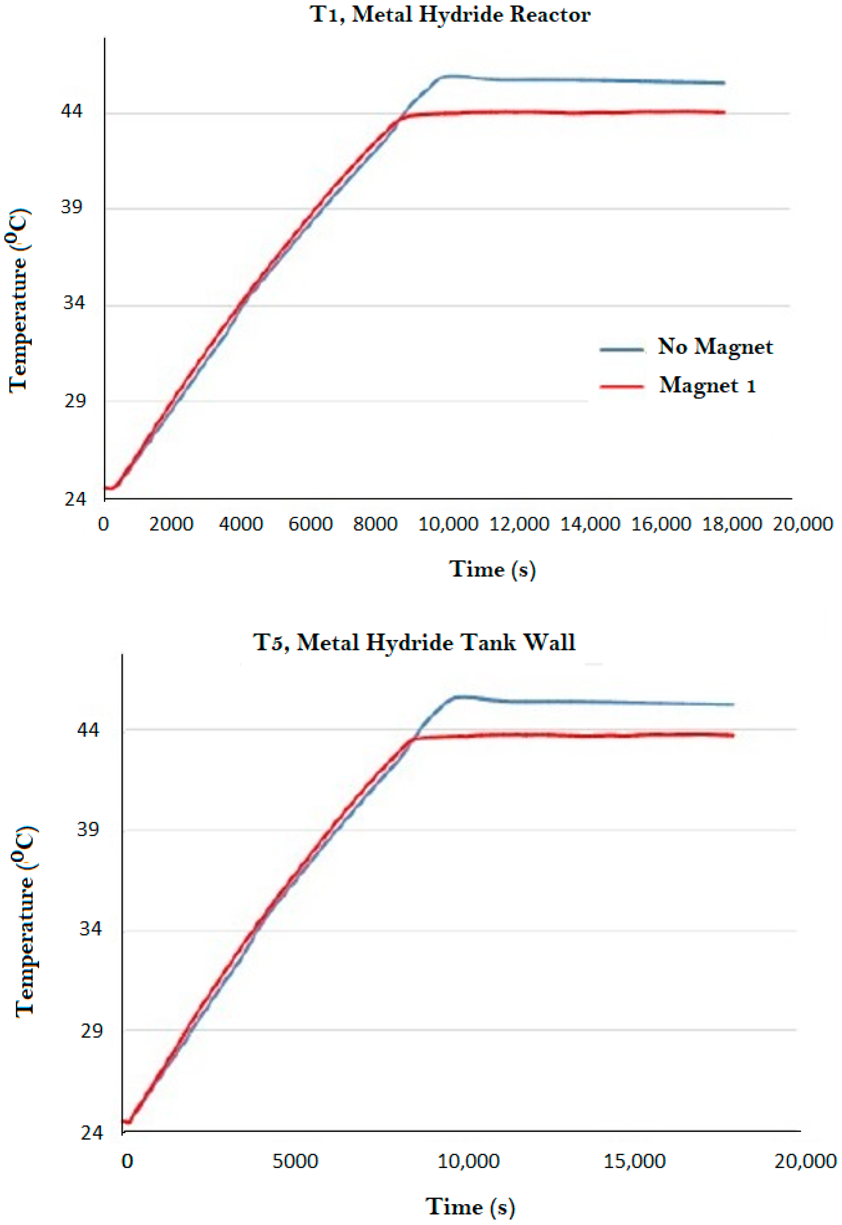
where T1 and T5 are the temperatures of thermocouples at the center of the reactor and at the wall, respectively, and the temperature values were used once steady state is reached. When magnet 1 is used, the results showed around 8–9% improvement in the thermal conductivity of bed. The error margin of the thermocouples used in this work is 1–2.5% for temperatures below 973 K. Temperatures at the center of the reactor and its wall with and without magnet 1 are depicted in Figure 5. It can be observed that the steady state was reached quickly when the magnet was used, indicating a faster heat transfer rate. It can also be observed from the figure that the maximum temperature is lower inside the metal hydride tank (T1) and on the reactor wall (T5) when the magnetic field is applied. This shows that using the magnetic field can enhance the heat transfer in metal hydride beds.
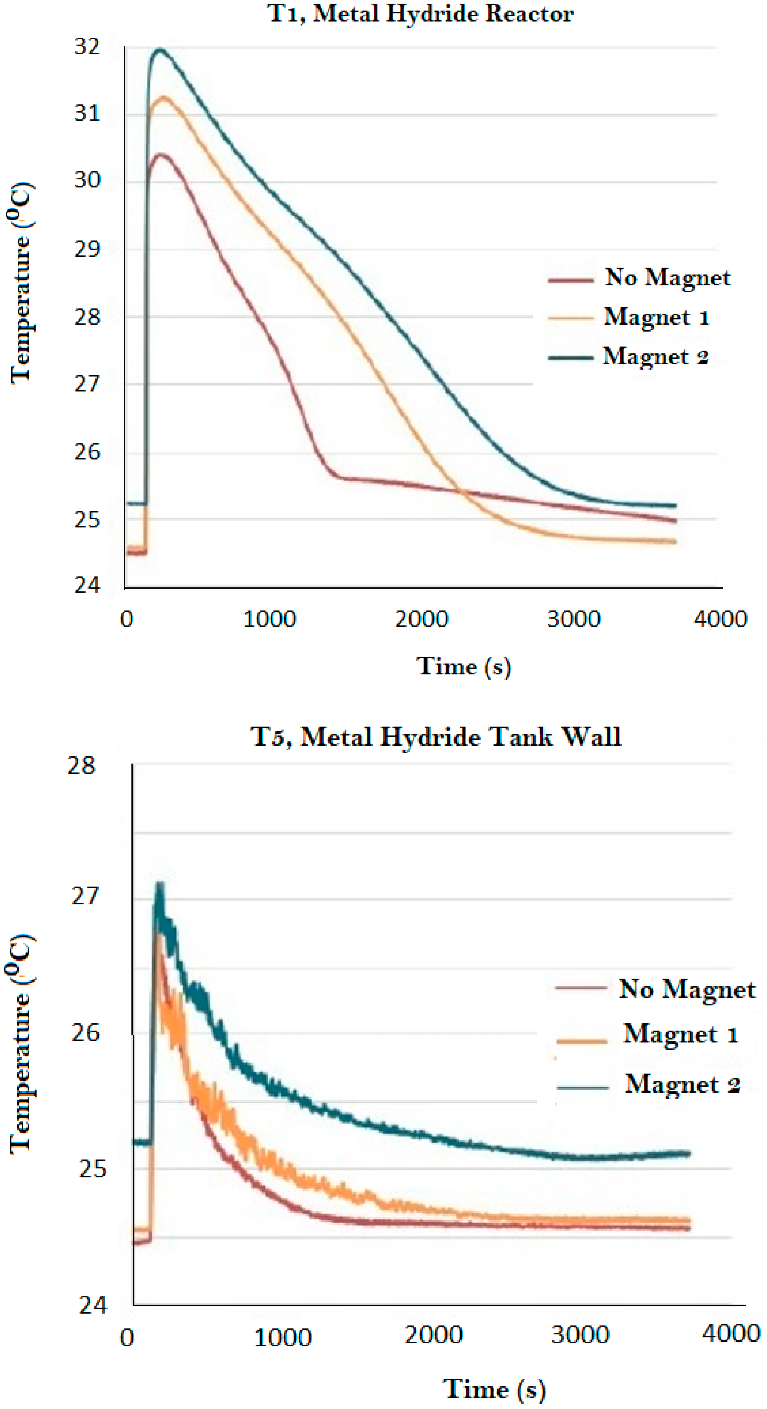
Considering that experimental results supported heat transfer enhancement in the LaNi5 bed under magnetism, a set of experiments were run to check the hydrogen absorption properties of lanthanum nickel under magnetism. In these experiments, magnets 1 and 2 are used to provide magnetic fields inside the reactor. Initially, experiments were done to check the amount of hydrogen absorption in the bed without any magnetic fields, and then two series of experiments with magnets 1 and 2 were performed. Temperature distributions of two sample experiments during the hydriding process inside the reactor and on its wall are illustrated in Figure 6.
Few conclusions can be drawn from Figure 6. From the temperature measurement inside the metal hydride reactor, it is seen that the maximum temperature is recorded as soon as hydrogenation initiated. Also, the temperature peak increases with increased magnetic flux. Considering that the heat source in these experiments is the released heat through exothermic hydrogen absorption reaction, it is concluded that the higher magnetic intensity enhances the rate at which the reaction takes place. In other words, the reaction kinetics are enhanced under the effect of the magnetic fields. Though the difference in temperatures under three cases is not significant before the reaction initiates, the difference in temperatures is more prominent during and after the reaction. This is due to the high energy released during the reaction and the dissipation of heat at different thermal conductivities in all the three cases.
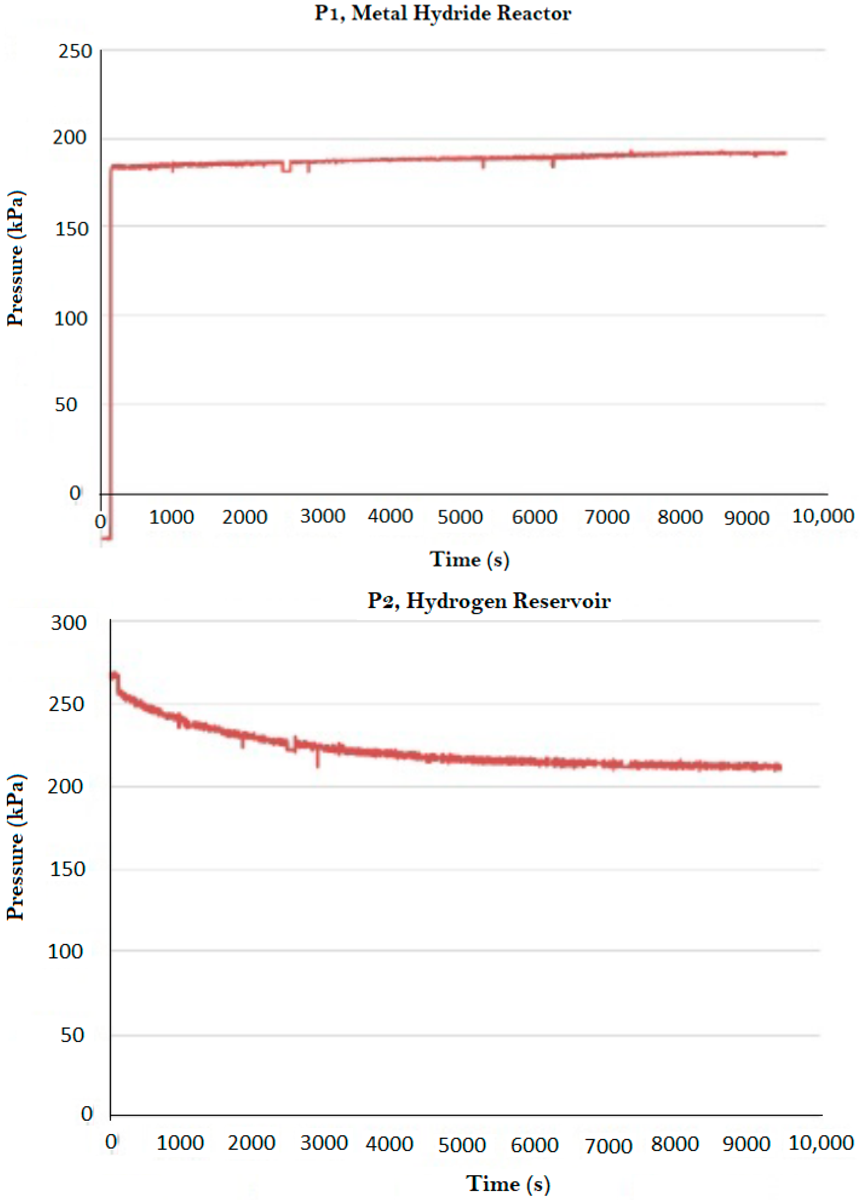
Measured pressures in the reactor and reservoir are presented in Figure 7. From the final pressures in the reactor as shown in Figure 7, at the end of data recording time the equilibrium pressure of reaction experiences a slight increase. Also, the rate of decrease in pressure of the reservoir shows that the time required to absorb an identical amount of hydrogen in each case is decreased by implementing magnetic fields. Thus, applying magnetic fields enhances hydrogen absorption time in a LaNi5 bed. It is postulated that the variation in equilibrium pressure and temperature is because of the decreased permeability and increased heat transfer area in the system, due to the compaction of particles when magnets are present.
The mass of absorbed hydrogen under each magnet is presented in Table 3. The mass is calculated by measuring the volume of absorbed hydrogen under normal conditions (T = 293 K & P = 101 kPa) and using the density of hydrogen under normal conditions (ρ = 0.089 kg/m3). The driving potential for the hydriding reaction is the difference between the metal hydride tank pressure and equilibrium pressure; the larger this difference is, the faster is the reaction rate. The rate can be increased by either increasing the pressure or reducing the metal hydride temperature. If sufficient cooling is provided during a small pressure increment during the pressure ramp, the metal hydride temperature will be maintained below the equilibrium temperature, and the reaction continues as the pressure increases by a second increment. However, if the cooling is insufficient, the metal hydride temperature reaches the equilibrium temperature and the reaction stalls. From the calculated absorbed hydrogen for each experiment, it is evident that magnetism increases the amount of hydrogen which can be absorbed in lanthanum nickel. The hydrogen absorption amount (practical absorption capacity) should not be confused with theoretical absorption capacity, which is 1.5% for LaNi5. The information presented in Table 3 is an indication of practical absorption capacity which can change by the change in the equilibrium condition of the chemical hydrogen absorption/desorption reactions. A change in the amount of absorbed hydrogen does not mean that there is a change to the theoretical hydrogen absorption capacity of the substance.
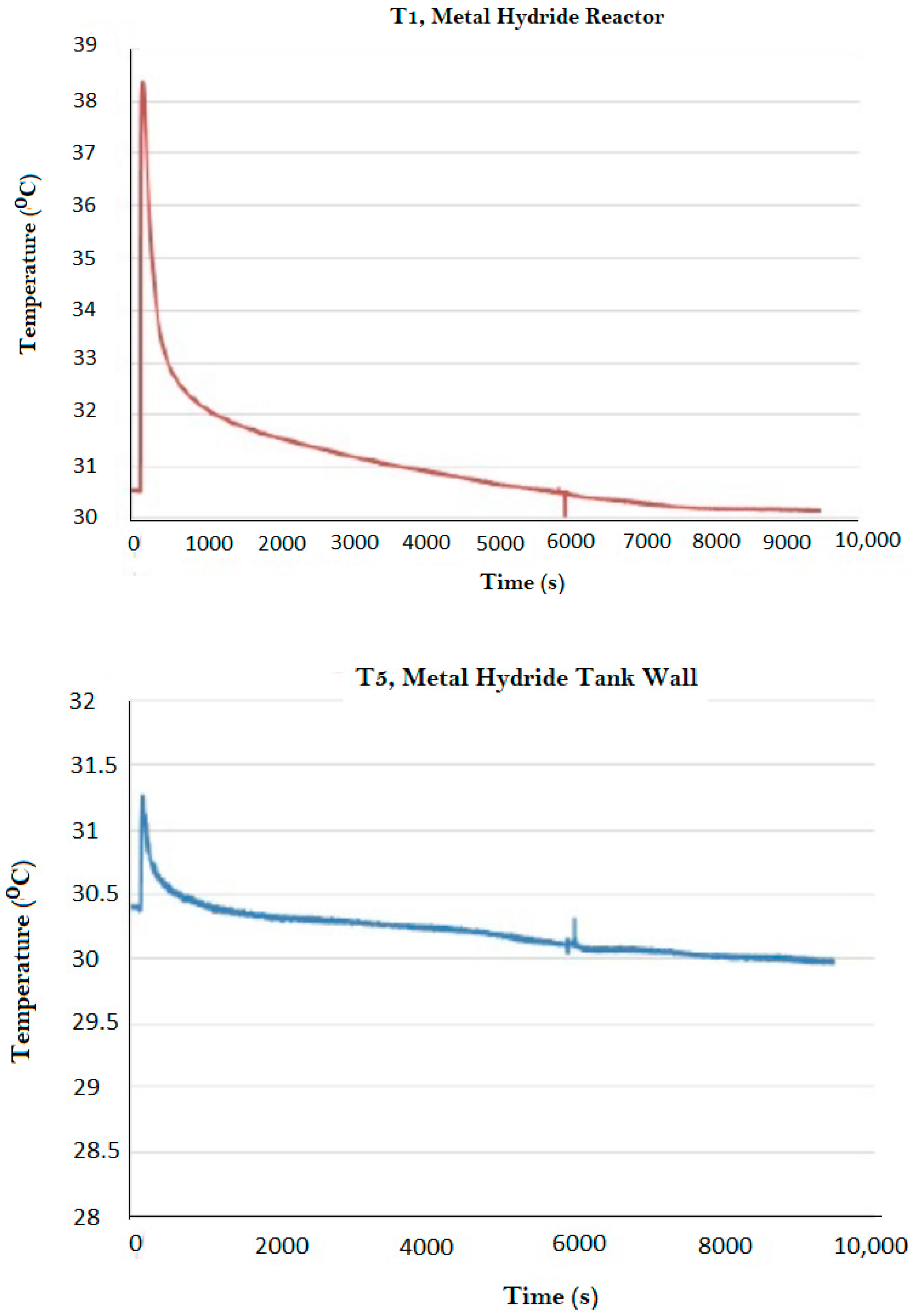
Thus far, the positive effect of magnetism on thermal conduction and hydrogen absorption capacity in LaNi5 was tested. A series of experiments were performed to identify whether improved hydrogenation properties are because of the chemical reaction or because of the enhanced heat transfer rates. In these experiments, a hydriding process was initiated without magnetism on the setup. When hydriding reaches equilibrium, a magnet (magnet 2) is placed at the bottom of the reactor which causes the sudden temperature fluctuation shown in Figure 8. The temperature slope changes by adding the magnet (as presented in Figure 8), which supports the previous conclusion of changed equilibrium temperature and pressure in a magnetic field. However, as there is no significant change in the temperature pattern, no extra hydrogenation occurs by adding a magnet. Meanwhile, as illustrated in Figure 9, pressure does not have any changed slope when the magnetic field is applied. Consequently, no more hydrogen absorption occurs at this stage. From this experiment, it is concluded that the chemical reaction does not change by magnetism and the enhanced hydrogenation properties of the hydride are because of the enhanced heat transfer rate.
4. Conclusions
This paper studied a new heat transfer enhancement method of using an external magnetic field to improve heat conduction inside a metal hydride bed. Experiments have proven that implementing an external magnetic field improves effective thermal conductivity, reaction kinetics, and hydrogenation in a lanthanum nickel bed. Improved hydrogenation properties are requirements of hydrogen storage in metal hydrides. The selected metal hydride (LaNi5) demonstrates magnetic properties which were utilized to apply the concept of increased heat transfer under magnetism, to improve hydrogenation properties of the metal hydride. However, magnetism did not increase the hydrogenation capacity of lanthanum nickel, which proves that elevated hydrogenation characteristics result from enhanced heat transfer in the bed. Considering that magnetic fields increase the heat transfer in both ferromagnetic and paramagnetic materials and many metal hydrides are paramagnetic, the same concept can be applied to any paramagnetic hydrogen absorbing medium.
Acknowledgments
Authors would like to thank the National Center for Hydrogen Research. The center supported this work by providing the funding and required facilities and equipment. The authors would also like to thank Johnathan Whitlow for his help in designing the experiments.
Author Contributions
Sarada Kuravi conceived the idea and designed the experiments. Shahin Shafiee performed the experiments and wrote the paper. Mary-Helen McCay contributed to materials and lab facilities. Mary-Helen McCay and Sarada Kuravi analyzed the data and proof-read the manuscript.
Conflicts of Interest
The authors declare no conflict of interest.
References
- Harries, D.N.; Paskevivius, M.; Sheppard, D.A.; Price, T.E.C.; Buckley, C.E. Concentrating Solar Thermal Heat Storage Using Metal Hydrides. Proc. IEEE 2012, 100, 539–549. [Google Scholar] [CrossRef]
- Sakintuna, B.; Lamari-Darkrim, F.; Hirscher, M. Metal hydride materials for solid hydrogen storage: A review. Int. J. Hydrogen Energy 2007, 32, 1121–1140. [Google Scholar] [CrossRef]
- Durbin, D.J.; Malardier-Jugroot, C. Review of Hydrogen Storage Techniques for on Board Vehicle Applications. Int. J. Hydrogen Energy 2013, 38, 14595–14617. [Google Scholar] [CrossRef]
- Gardiner, M.R.; Burke, A. Comparison of hydrogen storage technologies: A focus on energy required for hydrogen input. ACS Div. Fuel Chem. 2002, 47, 794–795, (Preprints). [Google Scholar]
- Muthukumar, P.; Groll, M. Metal Hydride Based Heating and Cooling Systems: A Review. Int. J. Hydrogen Energy 2010, 35, 3817–3831. [Google Scholar] [CrossRef]
- Werner, R.; Groll, M. Two-stage metal hydride heat transformer laboratory model: Results of reaction bed tests. J. Less Common Met. 1991, 172, 1122–1129. [Google Scholar] [CrossRef]
- Groll, M. Reaction beds for dry sorption machines. Heat Recovery Syst. CHP 1993, 13, 341–346. [Google Scholar] [CrossRef]
- Supper, W.; Groll, M.; Mayer, U. Reaction kinetics in metal hydride reaction beds with improved heat and mass transfer. J. Less Common Met. 1984, 104, 279–286. [Google Scholar] [CrossRef]
- Aardahl, C.L.; Rassat, S.D. Overview of Systems Considerations for On-Board Chemical Hydrogen Storage. Int. J. Hydrogen Energy 2009, 34, 6676–6683. [Google Scholar] [CrossRef]
- Liu, Z.Q.; Marder, T.B. B–N versus C–C: How similar are they? Angew. Chem. Int. Ed. 2008, 47, 242–244. [Google Scholar] [CrossRef] [PubMed]
- Marder, T.B. Will we soon be fueling our automobiles with ammonia–borane? Angew. Chem. Int. Ed. 2007, 46, 8116–8118. [Google Scholar] [CrossRef] [PubMed]
- Kong, V.C.Y.; Kirk, D.W.; Foulkes, F.R.; Hinatsu, J.T. Development of hydrogen storage for fuel cell generators. II: Utilization of calcium hydride and lithium hydride. Int. J. Hydrogen Energy 2003, 28, 205–214. [Google Scholar] [CrossRef]
- Kim, K.J.; Montoya, B.; Razani, A.; Lee, K.H. Metal Hydride Compacts of Improved Thermal Conductivity. Int. J. Hydrogen Energy 2001, 26, 609–613. [Google Scholar] [CrossRef]
- Visaria, M.; Mudawar, I.; Pourpoint, T.; Kumar, S. Study of heat transfer and kinetics parameters influencing the design of heat exchangers for hydrogen storage in high-pressure metal hydrides. Int. J. Heat Mass Transf. 2010, 53, 2229–2239. [Google Scholar] [CrossRef]
- Walker, G. Solid-State Hydrogen Storage: Materials and Chemistry; Woodhead Publishing: Cambridge, UK, 2008. [Google Scholar]
- Mori, D.; Hirose, K. Recent challenges of hydrogen storage technologies for fuel cell vehicles. Int. J. Hydrogen Energy 2009, 34, 4569–4575. [Google Scholar] [CrossRef]
- Schlapbach, L.; Zuttel, A. Hydrogen-Storage Materials for Mobile Applications. Nature 2001, 414, 353–358. [Google Scholar] [CrossRef] [PubMed]
- Poirier, E.; Dailly, A. Thermodynamic study of the adsorbed hydrogen phase in Cu-based metal-organic frameworks at cryogenic temperatures. J. Phys. Chem. C 2008, 112, 13047–13052. [Google Scholar] [CrossRef]
- Mellouli, S.; Askri, F.; Dhaou, H.; Jemni, A.; Nasrallah, S.B. Parametric Studies on a Metal-Hydride Cooling System. Int. J. Hydrogen Energy 2009, 34, 3945–3952. [Google Scholar] [CrossRef]
- Kim, K.J.; Feldman, K.T.; Lloyd, G.; Razani, A.; Shanahan, K.L. Performance of High Power Metal Hydride Reactors. Int. J. Hydrogen Energy 1998, 23, 355–362. [Google Scholar] [CrossRef]
- Suda, S.; Komazaki, Y.; Kobayashi, N. Effective thermal conductivity of metal hydride beds. J. Less Common Met. 1983, 89, 317–324. [Google Scholar] [CrossRef]
- Yang, F.S.; Wang, G.X.; Zhang, Z.X.; Meng, X.Y.; Rudolph, V. Design of the Metal Hydride Reactors—A Review on the Key Technical Issues. Int. J. Hydrogen Energy 2010, 35, 3832–3840. [Google Scholar] [CrossRef]
- Mellouli, S.; Askri, F.; Dhaou, H.; Jemni, A.; Nasrallah, S.B. Numerical Study of Heat Exchanger Effects on Charge/Discharge Times of Metal-Hydrogen Storage Vessel. Int. J. Hydrogen Energy 2009, 34, 3005–3017. [Google Scholar] [CrossRef]
- Kaplan, Y.; Veziroglu, T.N. Mathematical Modelling of Hydrogen Storage in a LaNi5 Hydride Bed. Int. J. Energy Res. 2003, 27, 1027–1038. [Google Scholar] [CrossRef]
- Cipiti, F.F.; Cacciola, G. Finite Element-Based Simulation of a Metal Hydride-Based Hydrogen Storage Tank. Int. J. Hydrogen Energy 2009, 34, 8574–8582. [Google Scholar]
- Ghafir, M.F.A.; Batcha, M.F.M.; Raghavan, V.R. Prediction of the Thermal Conductivity of Metal Hydrides—The Inverse Problem. Int. J. Hydrogen Energy 2009, 34, 7125–7130. [Google Scholar] [CrossRef] [Green Version]
- Bershadsky, E.; cJosephy, Y.; Ron, M. Permeability and Thermal Conductivity of Porous Metallic Matrix Hydride Compacts. J. Less Common Met. 1989, 153, 65–78. [Google Scholar] [CrossRef]
- Ron, M.; Bershadsky, E.; Josephy, Y. The Thermal Conductivity of Porous Metal Matrix Hydride Compacts. J. Less Common Met. 1991, 172–174, 1138–1146. [Google Scholar] [CrossRef]
- Sanchez, R.; Klein, H.P.; Groll, M. Expanded Graphite as Heat Transfer Matrix in Metal Hydride Beds. Int. J. Hydrogen Energy 2003, 28, 515–527. [Google Scholar]
- Klein, H.P.; Groll, M. Heat Transfer Characteristics of Expanded Graphite Matrices in Metal Hydride Beds. Int. J. Hydrogen Energy 2004, 29, 1503–1511. [Google Scholar] [CrossRef]
- Lee, M.; Kim, K.J.; Hopkins, R.R.; Gawlik, K. Thermal Conductivity Measurements of Copper-Coated Metal Hydrides (LaNi5, Ca0.6Mm0.4Ni5, and LaNi4.75Al0.25) for Use in Metal Hydride Hydrogen Compression Systems. Int. J. Hydrogen Energy 2009, 34, 3185–3190. [Google Scholar] [CrossRef]
- Asano, K.; Yamazaki, Y.; Iijima, Y. Hydrogenation and Dehydrogenation Behavior of LaNi5−xCox (x = 0, 0.25, 2) Alloys Studied by Pressure Differential Scanning Calorimetry. Mater. Trans. 2002, 43, 1095–1099. [Google Scholar] [CrossRef]
- Dhaou, H.; Askri, F.; Salah, M.B.; Jemni, A.; Nasrallah, S.B.; Lamloumi, J. Measurement and Modelling of Kinetics of Hydrogen Sorption by LaNi5 and Two Related Pseudobinary Compounds. Int. J. Hydrogen Energy 2007, 32, 576–587. [Google Scholar] [CrossRef]
- Pukazhselvan, D.; Kumar, V.; Singh, S.K. High Capacity Hydrogen Storage: Basic Aspects, New Developments and Milestones. Nano Energy 2012, 1, 566–589. [Google Scholar] [CrossRef]
- Mosher, D.A.; Tang, X.; Brown, R.J.; Arsenault, S.; Saitta, S.; Laube, B.L.; Dold, R.H.; Anton, D.L. High Density Hydrogen Storage System Demonstration Using NaAlH4 Based Complex Compound Hydrides; United Technologies Research Center: East Hartford, CT, USA, 2007. [Google Scholar]
- Bahadori, R.; Gutierrez, H.; Manikonda, S.; Meinke, R. Monte Carlo method simulation for two-dimensional heat transfer in homogenous medium and proposed application to quench propagation simulation. IEEE Trans. Appl. Supercond. 2017, 27, 1–5. [Google Scholar] [CrossRef]
- Shafiee, S.; McCay, M.H. Different Reactor and Heat Exchanger Configurations for Metal Hydride Hydrogen Storage Systems—A Review. Int. J. Hydrogen Energy 2016, 41, 9462–9470. [Google Scholar] [CrossRef]
- Shafiee, S. A Method to Enhance the Heat Transfer Mechanism in Metal Particle Porous Beds with Applicability to Paramagnetic Materials for Hydrogen Storage. Ph.D. Thesis, Florida Institute of Technology, Melbourne, FL, USA, 2016. [Google Scholar]
- Shafiee, S.; McCay, M.H.; Kuravi, S. Effect of Magnetic Fields on Thermal Conductivity in a Ferromagnetic Packed Bed. Exp. Therm. Fluid Sci. 2017, 86, 160–167. [Google Scholar] [CrossRef]
- Zhang, Z.T.; Guo, Q.T.; Yu, F.Y.; Li, J.; Zhang, J.; Li, T.J. Motion Behavior of Non-Metallic Particles under High Frequency Magnetic Field. Trans. Nonferr. Met. Soc. China 2009, 19, 674–680. [Google Scholar] [CrossRef]
- Mei, M.R.; Klausner, J.F.; Rahmatian, N. Interaction Forces Between Soft Magnetic Particles in Uniform and Non-Uniform Magnetic Fields. Acta Mech. Sin. 2010, 26, 921–929. [Google Scholar]
- Stucki, F.; Schlapbach, L. Magnetic Properties of LaNi5, FeTi, Mg2Ni and Their Hydrides. J. Less Common Met. 1980, 74, 143–151. [Google Scholar] [CrossRef]
- Kim, G.H.; Chun, C.H.; Lee, S.G.; Lee, J.Y. A Studey on the Microstructural Change of Surface of the Intermetallic Compound LaNi5 by Hydrogen Absorption. Scr. Metall. Mater. 1993, 29, 485–490. [Google Scholar] [CrossRef]
- Liu, N.; Ma, Q.M.; Xie, Z.; Liu, Y.; Li, Y.C. Structures, Stabilities and Magnetic Moments of Small Lanthanum-Nickel Clusters. Chem. Phys. Lett. 2007, 436, 184–188. [Google Scholar] [CrossRef]
- Alam, F.A.; Matar, S.F.; Nakhl, M.; Ouaini, N. Investigation of Changes in Crystal and Electronic Structures by Hydrogen within LaNi5 from First-Principles. Solid State Sci. 2009, 11, 1098–1106. [Google Scholar] [CrossRef]
- Albertini, F.; Canepa, F.; Cirafici, S.; Franceschi, E.A.; Napoletano, M.; Paoluzi, A.; Pareti, L.; Solzi, M. Composition Dependence of Magnetic and Magnetothermal Properties of Ni-Mn-Ga Shape Memory Alloys. J. Magn. Magn. Mater. 2004, 272–276, 2111–2112. [Google Scholar] [CrossRef]
- Marcos, J.; Manosa, L.; Planes, A.; Casanova, F.; Batlle, X.; Labarta, A.; Martinez, B. Magnetic Field Induced Entropy Change and Magnetoelasticity in Ni-Mn-Ga Alloys. J. Magn. Magn. Mater. 2004, 272–276, 224413. [Google Scholar] [CrossRef]
- Grechnev, G.E.; Logosha, A.V.; Panfilov, A.S.; Kuchin, A.G.; Vasijev, A.N. Effect of Pressure on the Magnetic Properties of YNi5, LaNi5, and CeNi5. Low Temp. Phys. 2011, 37, 138. [Google Scholar] [CrossRef]
- LaNi5; SDS No. 685933; Sigma-Aldrich: Saint Louis, MO, USA, 16 November 2017.
Figure 1.
Comparison of kWhr/kg of hydrogen and total system volume for different hydrogen storage technologies.
Figure 1.
Comparison of kWhr/kg of hydrogen and total system volume for different hydrogen storage technologies.

Figure 2.
Capacity comparison of different storage techniques. Adapted with permission from [14], ©Elsevier, 2009.
Figure 2.
Capacity comparison of different storage techniques. Adapted with permission from [14], ©Elsevier, 2009.

Figure 3.
Effect of metal hydride thermal conductivity on hydrogen fill time [14]; fill time can be greatly reduced for thermal conductivity higher than 2 W/(m·K).
Figure 3.
Effect of metal hydride thermal conductivity on hydrogen fill time [14]; fill time can be greatly reduced for thermal conductivity higher than 2 W/(m·K).
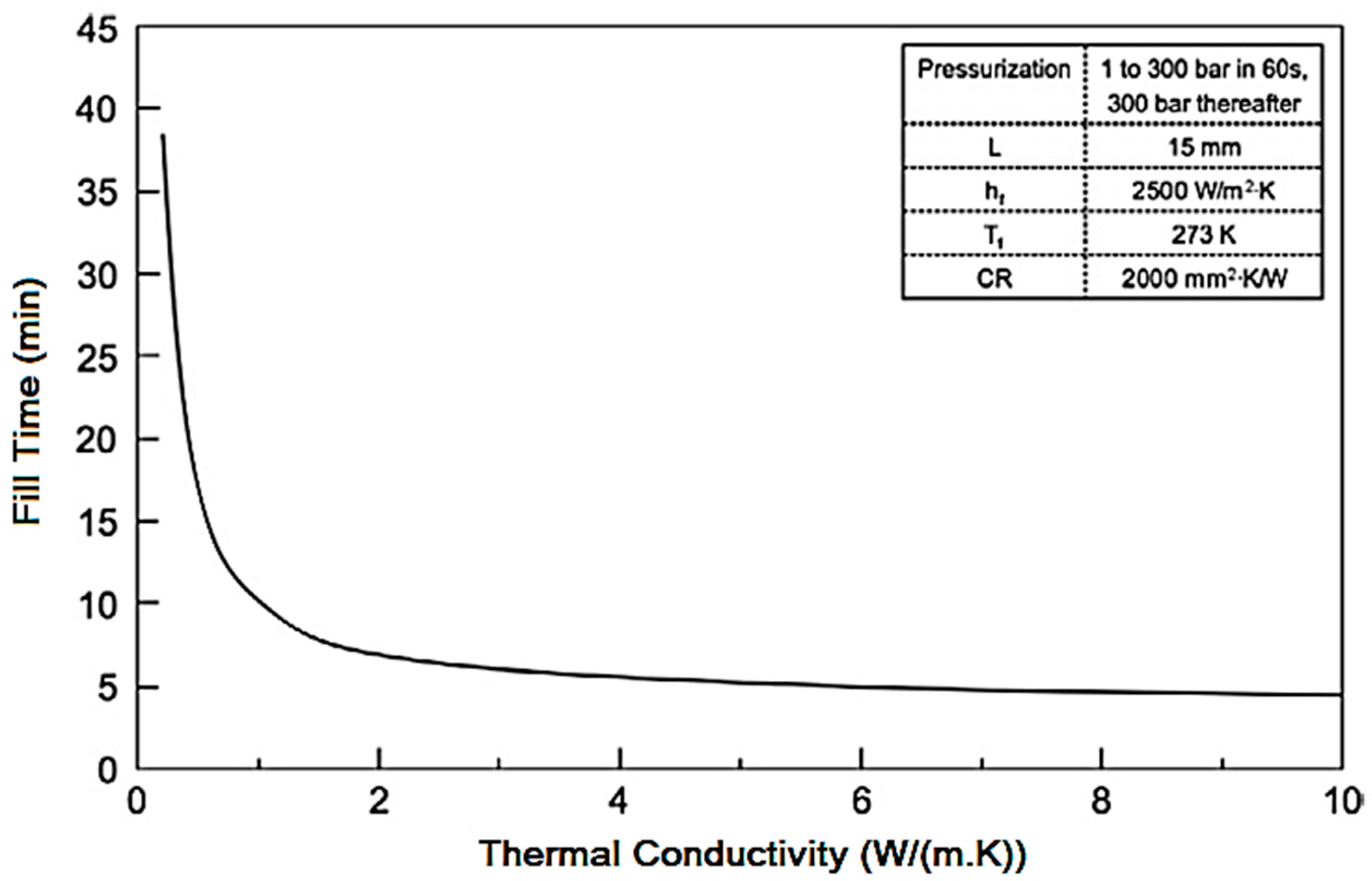
Figure 4.
Hydrogen storage setup and its schematic diagram showing the components.
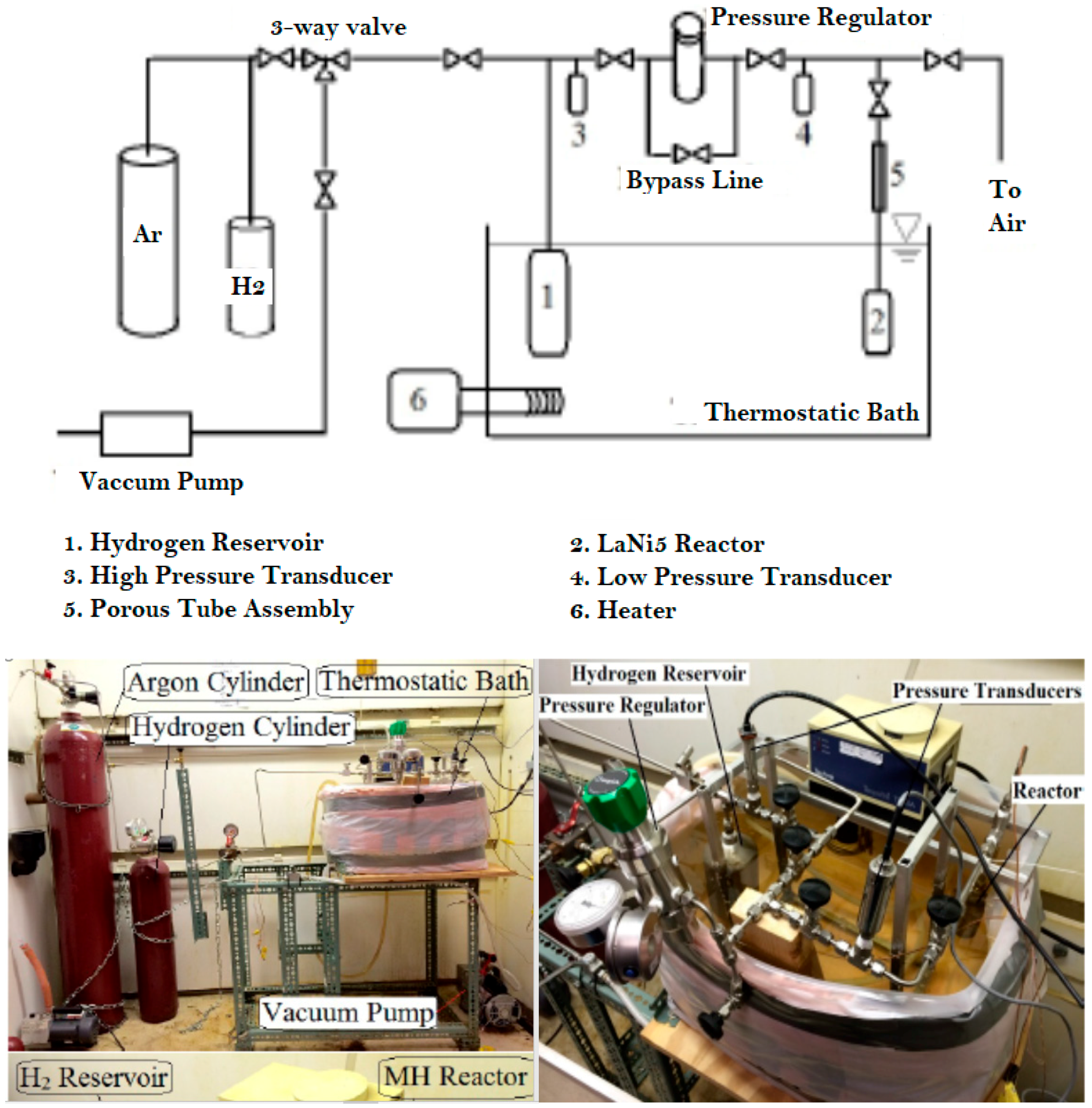
Figure 5.
Temperature measurements of the reactor (Top) and wall (Bottom) with and without magnet in LaNi5 bed during heat conduction experiments. Steady state is reached faster when magnet is present.
Figure 5.
Temperature measurements of the reactor (Top) and wall (Bottom) with and without magnet in LaNi5 bed during heat conduction experiments. Steady state is reached faster when magnet is present.

Figure 6.
Temperature measurement inside reactor (Top) and on its wall (Bottom) during hydrogenation.
Figure 6.
Temperature measurement inside reactor (Top) and on its wall (Bottom) during hydrogenation.

Figure 7.
Pressure measurement inside reactor (Top) and reservoir (Bottom) during hydrogenation under different magnetic conditions.
Figure 7.
Pressure measurement inside reactor (Top) and reservoir (Bottom) during hydrogenation under different magnetic conditions.
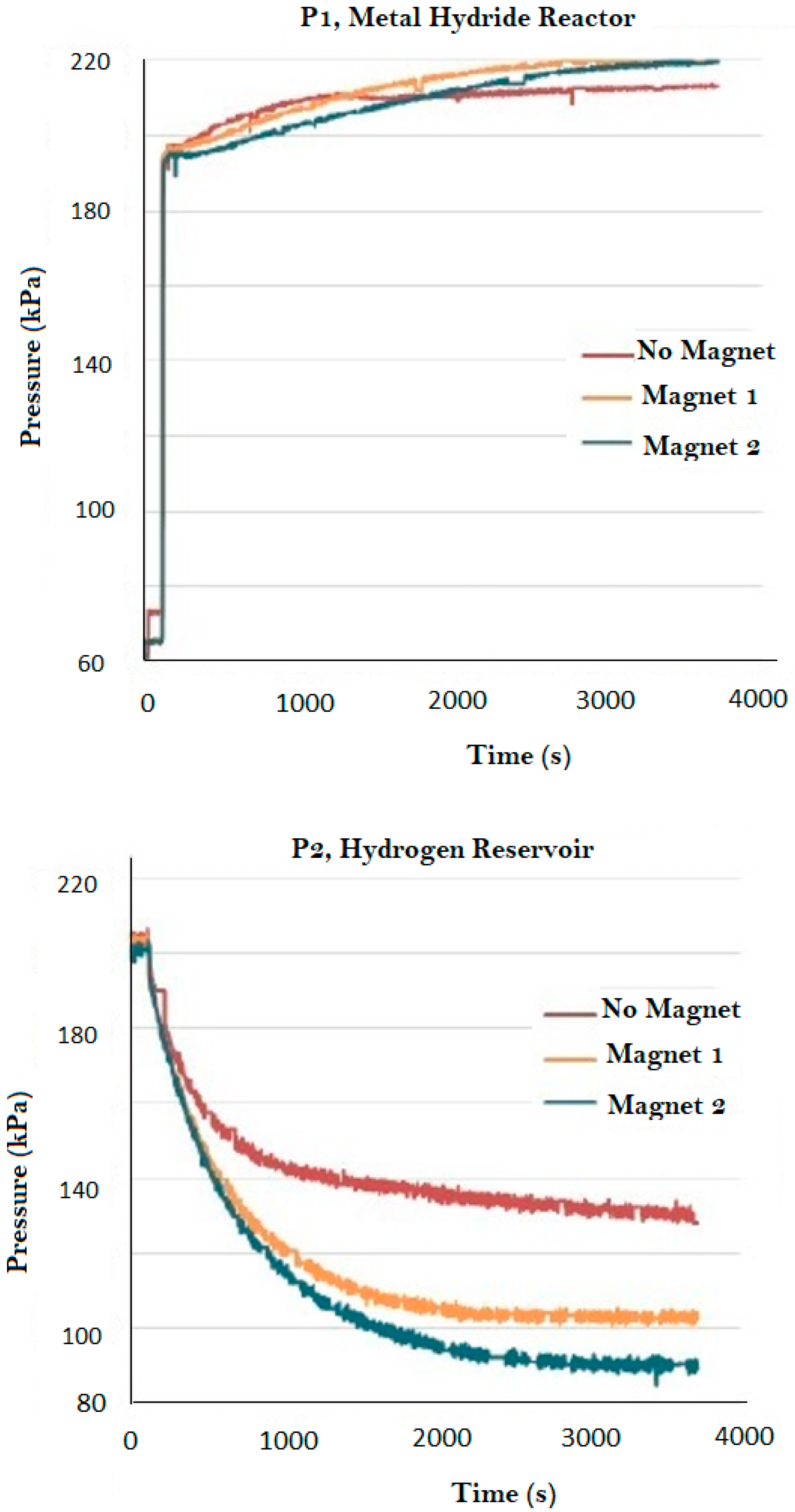
Figure 8.
Temperature measurement inside reactor (Top) and the tank wall (Bottom) during hydrogenation.
Figure 8.
Temperature measurement inside reactor (Top) and the tank wall (Bottom) during hydrogenation.

Figure 9.
Pressure measurement inside reactor (Top) and reservoir (Bottom) during hydrogenation.


Table 1.
Magnetic intensities of selected magnets.
| Magnet Number | Thickness (cm) | Nominal Intensity (Gauss) |
|---|---|---|
| 1 | 1.27 | 2952 |
| 2 | 2.54 | 4667 |
Table 2.
Thermocouple positions in hydrogen storage setup.
| Thermocouple | Position |
|---|---|
| T1 | Metal hydride reactor |
| T2 | Hydrogen reservoir |
| T3 | Thermostatic bath |
| T4 | Room temperature |
| T5 | Reactor wall |
Table 3.
Mass of absorbed hydrogen under different magnetic conditions.
| Boundary Condition | Δm (gr) |
|---|---|
| No magnet | 0.619 |
| Magnet 1 | 0.818 |
| Magnet 2 | 0.909 |
© 2017 by the authors. Licensee MDPI, Basel, Switzerland. This article is an open access article distributed under the terms and conditions of the Creative Commons Attribution (CC BY) license (http://creativecommons.org/licenses/by/4.0/).
Share and Cite
MDPI and ACS Style
Shafiee, S.; McCay, M.H.; Kuravi, S. The Effect of Magnetic Field on Thermal-Reaction Kinetics of a Paramagnetic Metal Hydride Storage Bed. Appl. Sci. 2017, 7, 1006. https://doi.org/10.3390/app7101006
AMA Style
Shafiee S, McCay MH, Kuravi S. The Effect of Magnetic Field on Thermal-Reaction Kinetics of a Paramagnetic Metal Hydride Storage Bed. Applied Sciences. 2017; 7(10):1006. https://doi.org/10.3390/app7101006
Chicago/Turabian StyleShafiee, Shahin, Mary Helen McCay, and Sarada Kuravi. 2017. "The Effect of Magnetic Field on Thermal-Reaction Kinetics of a Paramagnetic Metal Hydride Storage Bed" Applied Sciences 7, no. 10: 1006. https://doi.org/10.3390/app7101006
Note that from the first issue of 2016, this journal uses article numbers instead of page numbers. See further details here.