A Hardware-Efficient Vector Quantizer Based on Self-Organizing Map for High-Speed Image Compression
by
 ,
,
Zunkai Huang
1,2,3 ,
,
Xiangyu Zhang
3,
Lei Chen
3,
Yongxin Zhu
1,
Fengwei An
3,*,
Hui Wang
1,* and
Songlin Feng
1 1
Shanghai Advanced Research Institute, Chinese Academy of Sciences, Shanghai 201210, China
2
University of Chinese Academy of Sciences, Beijing 100049, China
3
School of Engineering, Hiroshima University, Hiroshima 739-8530, Japan
*
Authors to whom correspondence should be addressed.
Appl. Sci. 2017, 7(11), 1106; https://doi.org/10.3390/app7111106
Submission received: 28 September 2017
/
Revised: 22 October 2017
/
Accepted: 24 October 2017
/
Published: 25 October 2017
Abstract
:This paper presents a compact vector quantizer based on the self-organizing map (SOM), which can fulfill the data compression task for high-speed image sequence. In this vector quantizer, we solve the most severe computational demands in the codebook learning mode and the image encoding mode by a reconfigurable complete-binary-adder-tree (RCBAT), where the arithmetic units are thoroughly reused. In this way, the hardware efficiency of our proposed vector quantizer is greatly improved. In addition, by distributing the codebook into the multi-parallel processing sub-blocks, our design obtains a high compression speed successfully. Furthermore, a mechanism of partial vector-component storage (PVCS) is adopted to make the compression ratio adjustable. Finally, the proposed vector quantizer has been implemented on the field programmable gate array (FPGA). The experimental results indicate that it respectively achieves a compression speed of 500 frames/s and a million connections per second (MCPS) of 28,494 (compression ratio is 64) when working at 79.8 MHz. Besides, compared with the previous scheme, our proposed quantizer achieves a reduction of 8% in hardware usage and an increase of 33% in compression speed. This means the proposed quantizer is hardware-efficient and can be used for high-speed image compression.

1. Introduction
High-speed image capture is one of the fundamental tasks for numerous industrial and scientific applications such as target tracking, optical scientific measurement, autonomous vehicles [1,2,3,4,5], etc. Generally, in high-speed vision systems, the challenges of insufficient bandwidth and storage are increasingly severe and gradually become the bottlenecks. In practice, image compression is widely considered as an effective approach to relieving the above-mentioned problems since it can reduce the data to a more manageable level before the image sequences are transmitted [6,7].
Vector quantization (VQ) is a popular data compression technique, which holds many superiors like scalable complexity and high compression ratio. Self-organizing map (SOM) is regarded as an extremely promising algorithm to implement VQ [8,9]. Vector quantizer based on the SOM always shows plenty of excellent features such as inherent parallelism, regular topology, and relatively less well-defined arithmetic operations. These features not only make the SOM-based vector quantizer quite favorable for hardware implementation but also enable it to achieve high-speed image compression.
Numerous vector quantizers have been presented in the previous literature [10,11,12,13]. Specifically, M. Fujibayashi et al. [10] developed a novel vector quantizer with a method of needless calculation elimination. Their work successfully decreased the computational cost to 40% of the conventional full-search scheme. Similarly, the authors in [12] employed a concept of operator sharing in their design and thus effectively reduced the complexity of each neural cell in SOM. Furthermore, to accelerate the best matching vector searching phase in VQ, W. Kurdthongmee [13] tactfully used the distance as the address of codebook memory to store index. This made the time for the best matching vector searching process decline to only one clock.
Overall, in the previously proposed vector quantizers, many techniques were adopted to reduce the calculation complexity in the image encoding phase and thus realized lower resource usage. Nevertheless, for the codebook generation phase, few special optimizations were carried out. The previous designs normally required dedicated circuits to accomplish the codebook generation task. Hence, their entire hardware resource usages might be still high. Furthermore, in the previous works, most authors paid much attention to achieving low hardware resource usage but often neglected the characteristic of high processing speed. Even though the authors in [13] presented a novel technique to accelerate the encoding process, the achievable speed of their quantizer was finally restricted by the intrinsic high-latency of their architecture.
To solve the above-mentioned issues, we propose a hardware-efficient vector quantizer for high-speed image compression. A reconfigurable complete-binary-adder-tree (RCBAT), where the arithmetic units are completely reused, is presented to reduce the hardware usage. The speed requirement of high-speed data compression is satisfied by distributing the codebook into the multi-parallel processing sub-blocks. Moreover, a mechanism of partial vector-component storage (PVCS) is adopted to make the compression ratio adjustable [14].
The rest of this paper is organized as follows: Section 2 briefly introduces the basic principle of SOM algorithm. Section 3 describes the proposed vector quantizer in detail. In Section 4, the verification system is developed based on the field programmable gate array (FPGA), and the experimental results are discussed as well. Finally, conclusions are provided in Section 5.
2. The Basic Principle of Self-Organizing Map
SOM is an unsupervised self-organizing neural network. It has been adopted to solve problems in a wide range of applications. Usually, SOM can compress information while preserving the most important topological and metric relationships of the input data [15]. A SOM is normally constructed by the components named neurons, which are arranged in the form of a two-dimension regular grid. Each neuron contains one d-dimension vector, Wi, called weight vector, where
During the learning step, neurons are adapted to the input vector by the criterion of similarity matching between the input vector and the weight vectors. In this way, the neurons in SOM can become more representative of the input data. Specifically, the input vectors can be expressed as
The neuron whose weight vector is the closest one to the input vector is regarded as the winner-neuron. The Euclidean distance is one of the most popular ways to measure the distance. It is defined as Equation (3), where R is the number of neurons and thus the winner-neuron can be expressed as Equation (4).
In general, the squared Euclidean distance (SED), (), is preferred over DE in hardware implementation since the root operation has no influence on the comparison result but will cause additional computational costs. Once the winner-neuron is determined, the weight vector of winner-neuron will be updated according to Equation (5).
In Equation (5), t is the discrete-time coordinate, and α(t) is the learning rate. Ws(t) and Ws(t + 1) represent the weight vectors of the winner-neuron before and after the updating process, respectively. As shown in Equation (5), the update procedure can be regarded as a gradual reduction of the component-wise difference between the input vector and weight vector of the winner-neuron. Geometrically speaking, the weight vector of the winner-neuron is moved towards the input vector and the step size of weight vector movement is affected by α(t). In order to drastically train the SOM, the winner-neuron searching process in Equation (4) and the weight vector updating process in Equation (5) repeat alternately to facilitate convergence after multiple iterations.
3. Proposed Vector Quantizer Based on SOM
3.1. The Overall Architecture
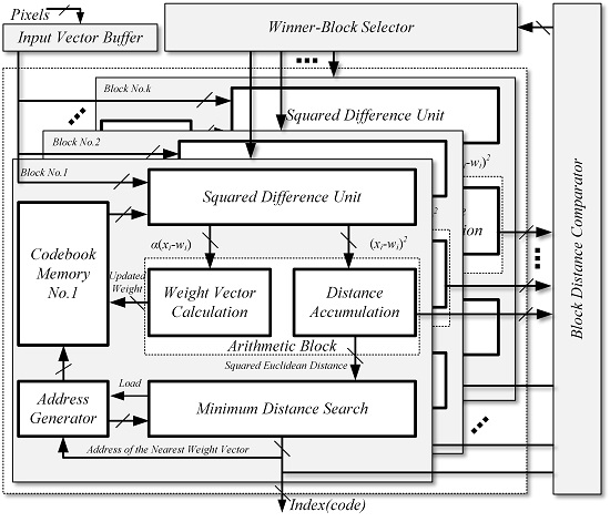
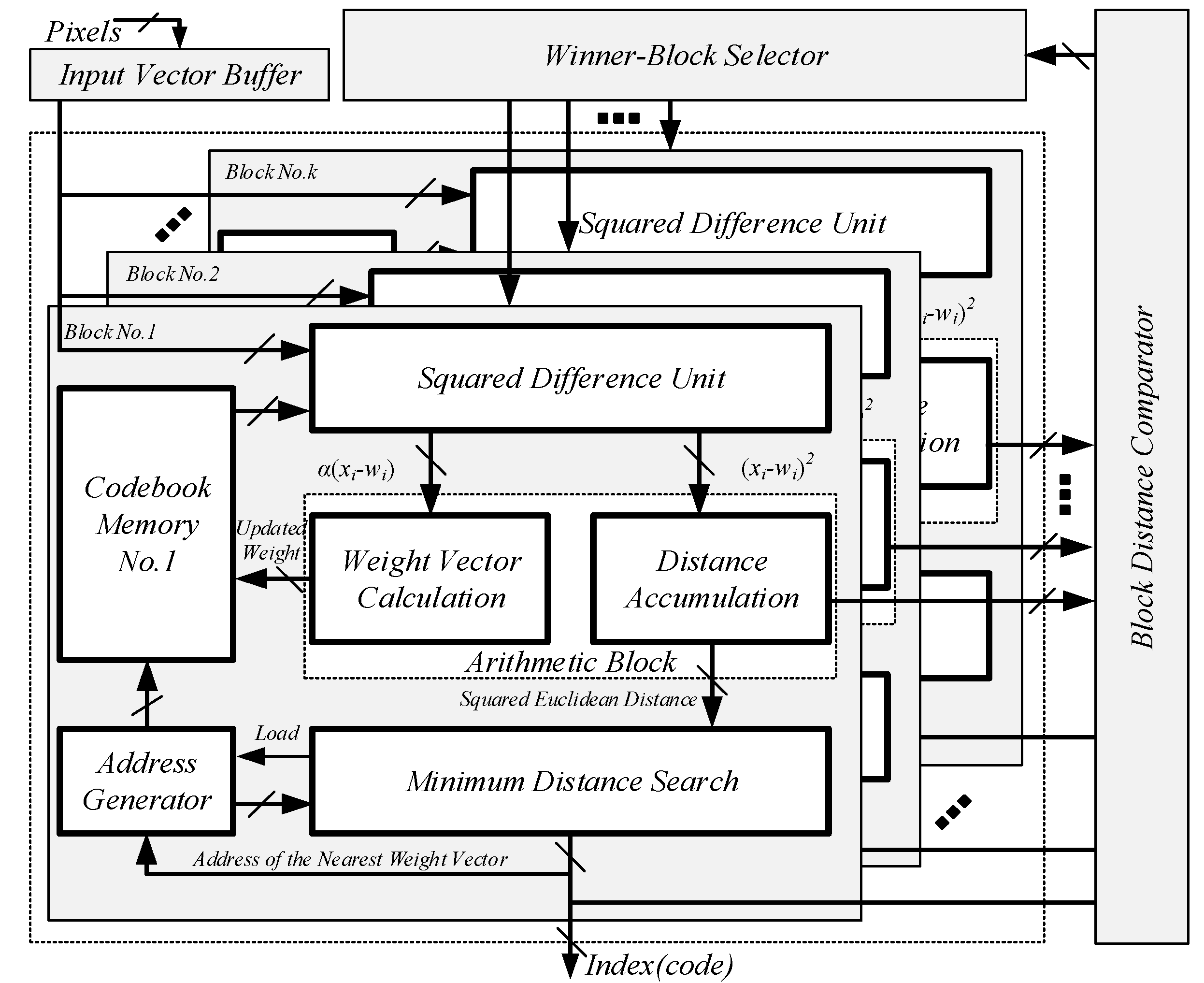
The overall architecture of the proposed vector quantizer is illustrated in Figure 1. It consists of an input buffer, k sub-blocks for codebook learning and image encoding, a block distance comparator, and a winner-block selector. To achieve a high image compression speed, we distribute the codebook into k sub-blocks. The operation principle of our proposed vector quantizer can be described as follows: firstly, the winner-neurons in each sub-block are found out and their corresponding minimum SEDs are output to the block distance comparator. In the block distance comparator, the k minimum SEDs are further compared. In this way, the sub-block where the winner-neuron exists is determined and then selected by the winner-block selector. Finally, the address of winner-neuron, as well as the results of block distance comparator, are output as the index.
As the most critical element, each sub-block is composed of the address generator and memory for the codebook, the squared difference unit (SDU), the arithmetic block, and the minimum distance search unit. In contrast with the previous works, where dedicated circuits were required for codebook learning, we have thoroughly utilized the design concept of reconfigurable architecture to improve the hardware efficiency. Specifically, the SDU and arithmetic block can be reconfigured either into codebook learning mode or into image encoding mode. As a consequence, both the operations of Euclidean distance computation and new weight vector generation, which are the main sources of high computational complexity, would be simultaneously executed by the SDU and arithmetic block without any additional circuits.
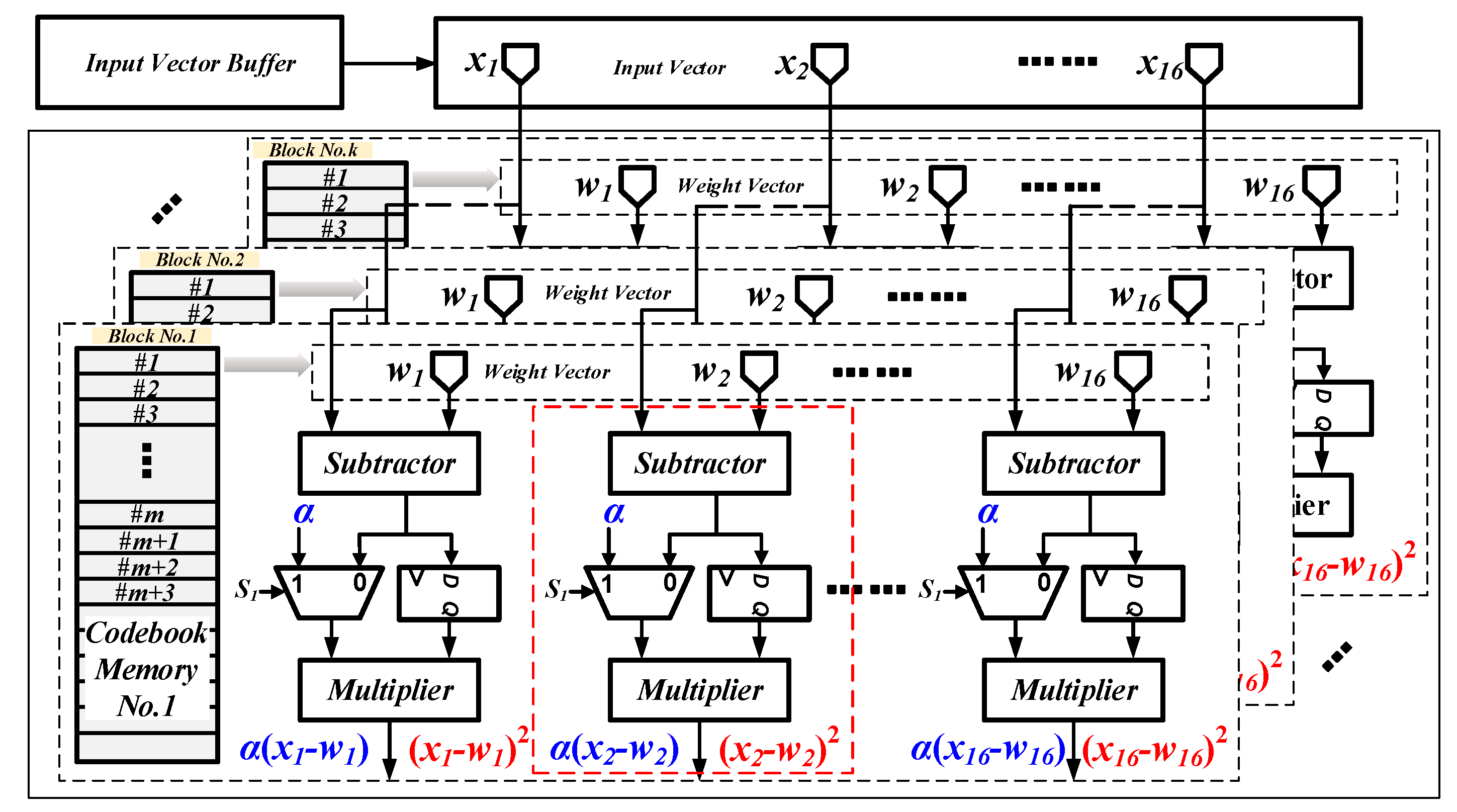
3.2. The Squared Difference Unit and Memory Block
The structure of SDU is illustrated in Figure 2. It mainly consists of numerous arithmetic units such as subtractors and multipliers as well as some auxiliary registers. To improve the hardware efficiency, several multiplexers are inserted between the subtractors and multipliers. All of the multiplexers are controlled by an independent signal “S1”. In this way, the data flow can be easily reconstructed by changing the value of “S1”. As depicted in Figure 2, the SDU can output either (xj − wij)2 or α(xj − wij), according to the value of signal “S1”. Since (xj − wij)2 and α(xj − wij) are separately the basic elements for SED calculating and new weight vector updating, the SDU can be successfully reconfigured in both codebook learning mode and image encoding mode without dedicated circuits.
As shown in Figure 2, the SDU can process a 16-dimensional vector in every clock. To enable our proposed vector quantizer to deal with high-dimensional vector, we apply a mechanism of partial vector-component storage (PVCS) in the codebook memory. Typically, the d-dimensional input vector and weight vector are distributed into 16 memory blocks, and each complete vector contains m partial vector, where m = ⌈d/16⌉. Once the address counter for the vector accessing equals to m, a separation signal “SSEP” is asserted, which implies that an individual vector has been accessed entirely.
3.3. The Arithmetic Block
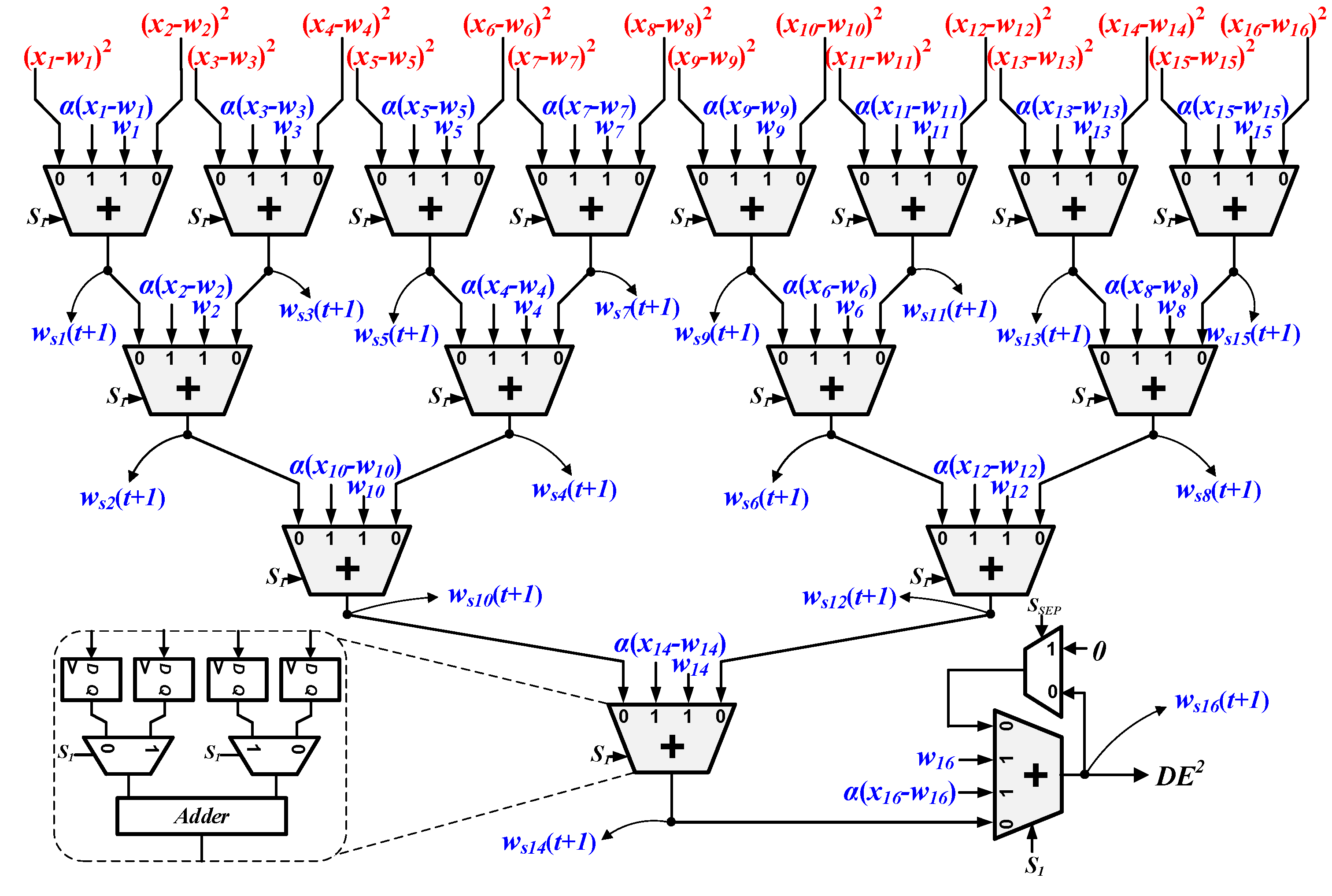
As discussed in Section 3.2, the SDU can merely calculate the basic elements, (xj − wij)2 and α(xj − wij), for distance calculating and weight vector updating. In order to obtain the absolute values of SED () and the new weight vector (Ws(t + 1)), extra calculations must be conducted. In our work, we proposed an optimized circuit named RCBAT to accomplish these operations.
Figure 3 shows the basic architecture of RCBAT. Similar to the SDU, the arithmetic block in our design can also be reconfigured either in codebook learning mode or in image encoding mode. In the image encoding mode, “S1” is set as “0”. The values of (xj − wij)2 are first computed by the SDU and then provided to the RCBAT. Next, the 16 separate squared differences are accumulated by the 4 pipeline stages in the RCBAT and thus 1 partial SED is obtained. As we adopt a mechanism of PVCS in the SDU, we must sum up all of the partial SEDs to get the exact SED. Hence, we add an additional stage following the fourth stage, which is shown at the right bottom of Figure 3. In the last stage, the separation signal “SSEP” keeps as “0” until all of the partial vectors have been processed (after m clock cycles). As shown in Figure 3, when “SSEP” is “0”, the last adder is configured to sum the new partial SED and the intermediate exact SED up. When “SSEP” turns to “1”, the exact value of SED, “DE2”, which contains m partial SEDs, will be obtained and then fed into the minimum distance search circuit for winner-neuron searching. In the codebook learning mode, “S1” is set to “1” once the winner-neuron searching phase is completed. The beginning address of the winner-neuron is first loaded to the read-port of the codebook memory and then the 16-dimensional partial weight vectors of the winner-neuron are read out in sequence. In the meantime, the SDU in Figure 2 is configured to compute the value of α(xj − wij), and the RCBAT is transformed to 16 individual adders to calculate the value of wij + α(xj − wij). The data flow of the RCBAT circuit is highlighted with blue color in Figure 3. In this way, the partial new weight vector can be smoothly obtained in one clock. Once it is written back to the codebook memory, the calculation procedure for the next partial new weight vector will be continued in the same manner. Finally, the entire new weight vector of the winner-neuron can be figured out and updated after m clocks.
Benefiting from the characteristic of configurability, all of the arithmetic units in SDU and arithmetic block can be substantially reused for SED accumulating and new weight vector updating. As a consequence, the hardware efficiency of our proposed vector quantizer is improved to a large degree.
3.4. Minimum Distance Search Circuit
As discussed in Section 2, the distances between the input vector and all of the weight vectors must be first computed and then compared with each other to find the winner-neuron. In our design, the distance calculation is fully conducted by the SDU and the RCBAT circuit, and the operation of minimum distance search is mainly executed by a winner-takes-all (WTA) circuit. The WTA circuit acts as an arbitration module which can locate the smallest SED and determine the winner-neuron.
The block diagram of the WTA circuit is depicted in Figure 4. It consists of a shifter register with a depth of ‘7’, three registers with load signal, one ‘AND’ gate, one comparator, and an additional ordinary register. The output port of the address generator for the codebook memory is connected to the input port of the shift register. The exact SED (DE2) from the RCBAT circuit is fed to the WTA circuit as an input, and the signal ‘SSEP’ acts as a separate signal for different SEDs. During the winner-neuron searching phase, the intermediate minimum SED and the corresponding address are temporally stored in R2 and R3. The separation signal ‘SSEP’ is the same one that has been discussed in the RCBAT circuit. Once ‘SSEP’ turns into ‘1’, the newly arrived SED ‘DE2’ is loaded in R1 and then compared with the intermediate minimum SED. If ‘DE2’ is the smaller one, the comparator would output ‘1’ and the values stored in R2, as well as R3, will be updated accordingly. After all of the weight vectors have been searched, the start address of the codebook memory where the current weight vector (winner-neuron) is stored will be output as an index and transmitted to the receiving terminal.
4. Experimental Results and Discussion
4.1. Hardware Implementation
The hardware of our proposed vector quantizer has been described by Verilog HDL(verilog hardware description language) and implemented on FPGA. Table 1 summarizes the hardware resource usages of the proposed vector quantizer. Similar to the previous hardware implementations, the learning rate α in our design is set as a constant value to simplify the control circuits. In addition, considering the trade-off between the memory resource usage and the visual quality degeneration, we define the codebook size as 256. To improve the processing speed, we set the number of sub-block as 32.
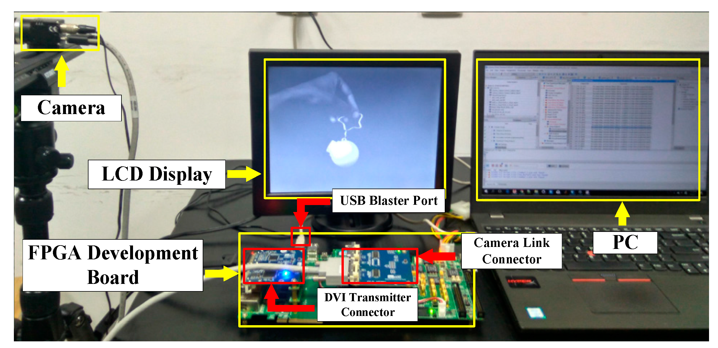
Under such conditions, the synthesis results indicate that the obtained maximum clock frequency is 79.8 MHz. Furthermore, to verify our design, an image compression system based on the proposed vector quantizer is developed for high-speed target tracking application and exhibited in Figure 5. As shown in Figure 5, the demonstration system is composed of a high-speed image sensor, a FPGA development board, a display, and a PC. The camera link connector and DVI (digital visual interface) transmitter connector are inserted into the FPGA board for image capture and display.
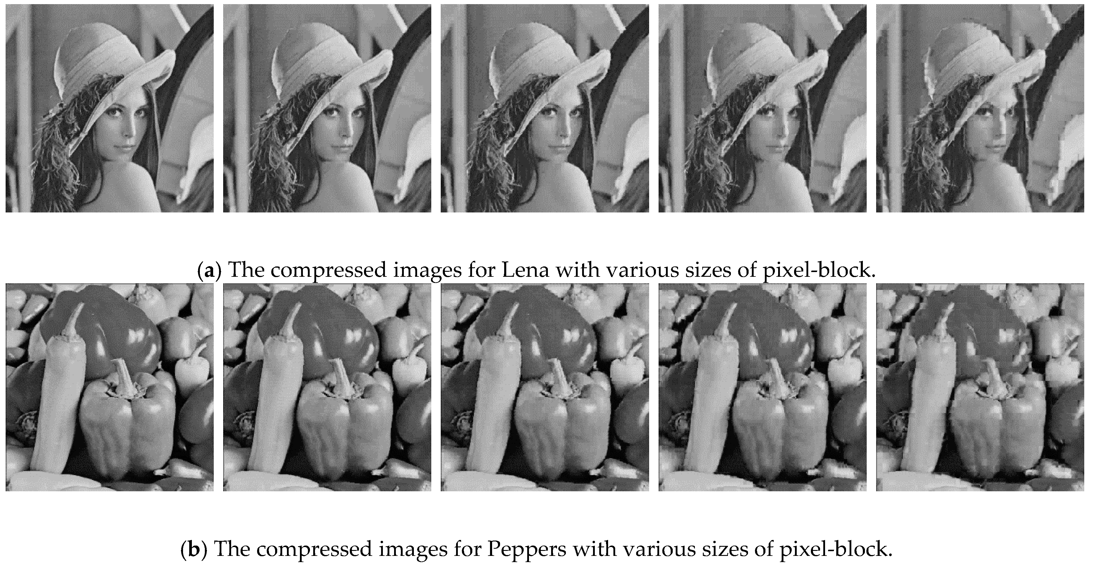
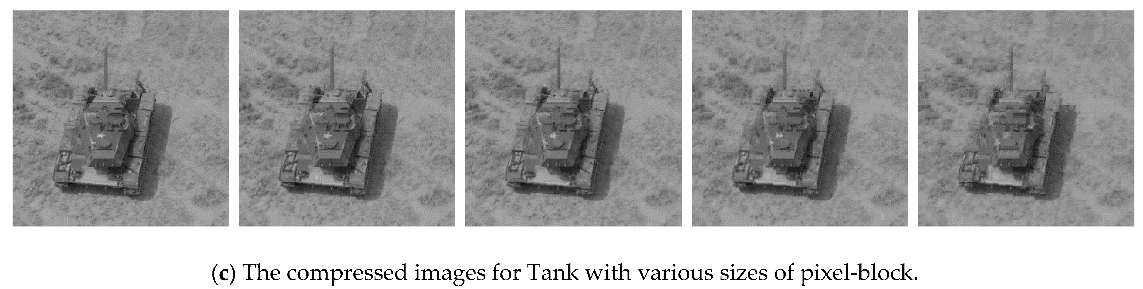
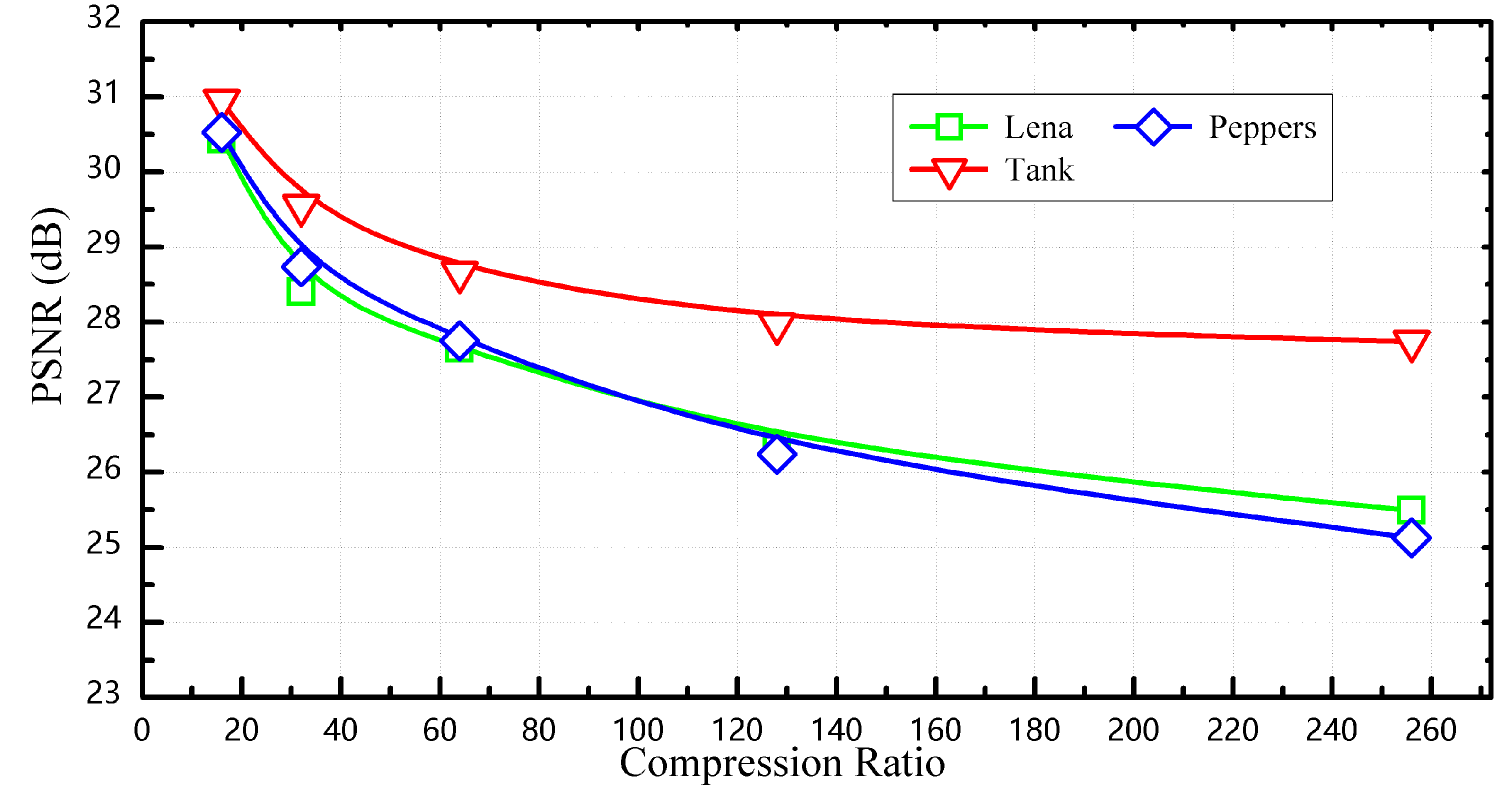
We have conducted several experiments to intuitively evaluate the compression performance of our proposed vector quantizer. To make the experimental results comparable, three standard grayscale 512 × 512-pixel images from the USC-SIPI (University of Southern California-Signal and Image Processing Institute) image database, respectively—Lena, Peppers, and Tank—were adopted as the test data. As mentioned before, the codebook size is set as 256, and the number of multi-parallel processing sub-blocks is set as 32. In this way, the 256 weight vectors are equally distributed into 32 blocks, and thus the processing speed is greatly improved. During the codebook generation phase, the pixel values of Lena are utilized as the training data. Once the phase of codebook generation is completed, Lena, Peppers, and Tank are encoded by the trained codebook in sequence. Moreover, several sizes of pixel-block including 4 × 4, 4 × 8, 8 × 8, 8 × 16, and 16 × 16 are employed to judge the visual quality of the reconstructed images with different compression ratio. Figure 6 shows the visual quality comparisons between the compressed images with various compression ratios. It can be seen that the compressed images are able to keep relatively acceptable visual quality even if the pixel-block of 8 × 8 is employed (the corresponding compression ratio is 64). Finally, the visual qualities of the compressed images with different compression ratios are quantified by the metric of peak signal-to-noise ratio (PSNR) and plotted in Figure 7. Figure 7 indicates that the PSNR of Lena in our work is about 30.69 dB as the compression ratio keeps to 16, which is slightly worse than that in [11]. That may stem from the truncation error in the fixed-point calculation when different types of word-precision are adopted. Finally, benefiting from the mechanism of PVCS, we can adjust the compression ratio by changing the value of m, which has been discussed in Section 3.2.
4.2. Speed Analysis
For the compression circuits, processing speed is one of the critical performances, especially when they are applied in some high-speed vision systems such as high-speed object tracking, motion analysis, etc. In terms of our proposed vector quantizer, the clock cycles to encode one individual pixel-block can be defined as Equation (6), where d, N, and k are the pixel-block size, the codebook size and the number of sub-blocks, respectively. The number ‘7’ represents the depth of the shift register in Figure 4, which is equal to the sum of 1 stage in SDU (shown in Figure 2), 5 stages in the RCBAT (shown in Figure 3) and 1 stage in WTA circuits (shown in Figure 4).
In addition, since updating a weight vector will additionally take ⌈d/16⌉ + 3 clock cycles, the learning time for each pixel-block can be calculated by Equation (7).
As a matter of fact, the compression speed of vector quantizer is determined by the encoding time. In our design, if the size of pixel-block is defined as 8 × 8, the clock cycles to encode each pixel-block can be calculated as 39 according to Equation (6). Hence, the clock cycles to encode a frame of the grayscale 512 × 512-pixel image will be 159,744, and the corresponding time can be calculated as 2 ms with a maximum frequency of 79.8 MHz. The short encoding time makes our vector quantizer capable of compressing the high-speed image sequence with a frame-rate of 500 frames/s. Moreover, if our proposed vector quantizer is fabricated by advanced CMOS (Complementary Metal Oxide Semiconductor)process, a higher work frequency can be reached, and thus a faster compression speed will be obtained accordingly.
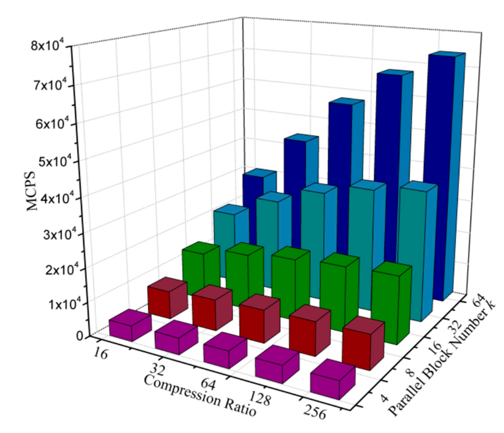
Furthermore, the million connections per second (MCPS) [16], which is a common metric to evaluate the performance of SOM, is also calculated according to Equation (8) and then plotted in Figure 8. Likewise, in Equation (8), d and N represent the pixel-block size and the codebook size, respectively. The results indicate that the value of MCPS reaches 28,494 when the size of pixel-block is 8 × 8 (compression ratio is 64) and the sub-block number is 32.
4.3. Comparisons
Performance comparisons between the proposed vector quantizer and the previous VQ-based compression circuits implemented in FPGA are conducted in this Section. Table 2 summarizes the comparison results. To make the data comparable, all of the parameters in Table 2 are calculated under the same condition. Particularly, the grayscale Lena with 512 × 512-pixel is employed as the test image.
As listed in Table 2, the values of PSNR are approximately equal for [11] and this work, and the higher value of PSNR for [13] is mainly due to the lower compression ratio of [13]. Besides, our proposed circuit seems to consume more LUTs than [11] when the parameter k is set as 32. However, this is merely caused by the large degree of block parallelism. Once we modulate the number of sub-blocks to 16, the proposed quantizer realizes a reduction of 8% in hardware usage even though its compression speed is 33% higher than that of [11]. In this way, a lower rate of hardware usage than [11] can be easily reached despite a higher compression speed than that of [11] being kept. The higher hardware efficiency of this work principally stems from the re-usage of arithmetic units in SDU and RCBAT. Moreover, Table 2 reveals that our vector quantizer achieves a higher compression speed than [13], even though [13] requires fewer clock cycles than our design for the minimum distance searching. This condition partially caused the high latency that introduced by the indispensable register file and other complicated modules in [13], but primarily arises from the high parallelism of our design. Finally, owing to the utilization of PVCS, the compression ratio of our proposed circuit is adjustable while those of the previous works are fixed.
5. Conclusions
Based on the SOM algorithm, we present a hardware-efficient vector quantizer to alleviate the challenges of insufficient bandwidth and storage in the high-speed vision system. A RCBAT circuit, which can be reconfigured both into the codebook learning mode and image encoding mode, is proposed to improve the hardware efficiency of our design. To achieve a high processing speed, we propose a multi-parallel architecture, where the codebook is evenly distributed into numerous sub-blocks. Moreover, by adopting a mechanism of PVCS, our vector quantizer easily acquires the advantage of adjustable compression ratio. Finally, a verification system is developed based on the FPGA. The experimental results indicate that the hardware resource usage and the achievable compression speed of our design are respectively 8% lower and 33% higher than that of the previous work. Overall, our proposed vector quantizer can effectively achieve a higher compression speed while keeping a lower hardware usage compared with the conventional design.
Acknowledgments
This work was supported by National Key Research and Development Program of China under Grant 2017YFA0206104, Shanghai Municipal Science and Technology Commission under Grant 16511108701, Zhangjiang Administrative Committee under Grant 2016-14, and China Scholarship Council.
Author Contributions
The design was conceived by Zunkai Huang and Fengwei An. Zunkai Huang performed the experiments, analyzed the data and wrote the manuscript under the supervision of Yongxin Zhu, Fengwei An, Hui Wang, and Songlin Feng. Xiangyu Zhang and Lei Chen provided technical support for architecture implementation.
Conflicts of Interest
The authors declare no conflict of interest.
References
- Xu, R.; Ng, W.C.; Yuan, J.; Yin, S.; Wei, S.A. 1/2.5 inch VGA 400 fps CMOS image sensor with high sensitivity for machine vision. IEEE J. Solid-State Circuits 2014, 49, 2342–2351. [Google Scholar] [CrossRef]
- Ishii, I.; Taniguchi, T.; Yamamoto, K.; Takaki, T. High-frame-rate optical flow system. IEEE Trans. Circuits Syst. Video Technol. 2012, 22, 105–112. [Google Scholar] [CrossRef]
- Jiang, M.; Gu, Q.; Aoyama, T.; Takaki, T.; Ishii, I. Real-Time Vibration Source Tracking Using High-Speed Vision. IEEE Sen. J. 2017, 17, 1513–1527. [Google Scholar] [CrossRef]
- Liu, X.; Sun, Q.; Zhang, C.; Wu, L. High-Speed Visual Analysis of Fluid Flow and Heat Transfer in Oscillating Heat Pipes with Different Diameters. Appl. Sci. 2016, 6, 321–336. [Google Scholar] [CrossRef]
- Cho, C.; Kim, J.; Kim, J.; Lee, S.J.; Kim, K.J. Detecting for high speed flying object using image processing on target place. Cluster Comput. 2016, 19, 285–292. [Google Scholar] [CrossRef]
- Baig, M.Y.; Lai, E.M.; Punchihewa, A. Compressed sensing-based distributed image compression. Appl. Sci. 2014, 4, 128–147. [Google Scholar] [CrossRef]
- Nishikawa, Y.; Kawahito, S.; Furuta, M.; Tamura, T. A high-speed CMOS image sensor with on-chip parallel image compression circuits. Proceedings of 2007 IEEE Custom Integrated Circuits Conference, San Jose, CA, USA, 16–19 September 2007; pp. 833–836. [Google Scholar]
- Huang, C.M.; Bi, Q.; Stiles, G.S.; Harris, R.W. Fast full search equivalent encoding algorithms for image compression using vector quantization. IEEE Trans. Image Process. 1992, 1, 413–416. [Google Scholar] [CrossRef] [PubMed]
- Horng, M.H. Vector quantization using the firefly algorithm for image compression. Expert Syst. Appl. 2012, 39, 1078–1091. [Google Scholar] [CrossRef]
- Fujibayashi, M.; Nozawa, T.; Nakayama, T.; Mochizuki, K.; Konda, M.; Kotani, K.; Ohmi, T. A still-image encoder based on adaptive resolution vector quantization featuring needless calculation elimination architecture. IEEE J. Solid-State Circuits 2003, 726–733. [Google Scholar] [CrossRef]
- Ramirez-Agundis, A.; Gadea-Girones, R.; Colom-Palero, R. hardware design of a massive-parallel, modular NN-based vector quantizer for real-time video coding. Microprocess. Microsyst. 2008, 32, 33–44. [Google Scholar] [CrossRef]
- Kurdthongmee, W. A novel hardware-oriented Kohonen SOM image compression algorithm and its FPGA implementation. J. Syst. Archit. 2008, 54, 983–994. [Google Scholar] [CrossRef]
- Kurdthongmee, W.A. A hardware centric algorithm for the best matching unit searching stage of the SOM-based quantizer and its FPGA implementation. J. Real-Time Image Proc. 2016, 12, 71–80. [Google Scholar] [CrossRef]
- Zhang, X.; An, F.; Chen, L.; Mattausch, H.J. Reconfigurable VLSI implementation for learning vector quantization with on-chip learning circuit. Jpn. J. Appl. Phys. 2016, 55, 04EF02. [Google Scholar] [CrossRef]
- Rauber, A.; Merkl, D.; Dittenbach, M. The growing hierarchical self-organizing map: Exploratory analysis of high-dimensional data. IEEE Trans. Neural Netw. 2002, 13, 1331–1341. [Google Scholar] [CrossRef] [PubMed]
- Hikawa, H.; Maeda, Y. Improved Learning Performance of Hardware Self-Organizing Map Using a Novel Neighborhood Function. IEEE Trans. Neural Netw. Learn. Syst. 2015, 26, 2861–2873. [Google Scholar] [CrossRef] [PubMed]
Figure 1.
The overall architecture of the proposed vector quantizer.

Figure 2.
Block diagram of the squared difference unit and its related data flow.

Figure 3.
The basic architecture of reconfigurable complete-binary-adder-tree.

Figure 4.
Block diagram of the winner-takes-all circuit.
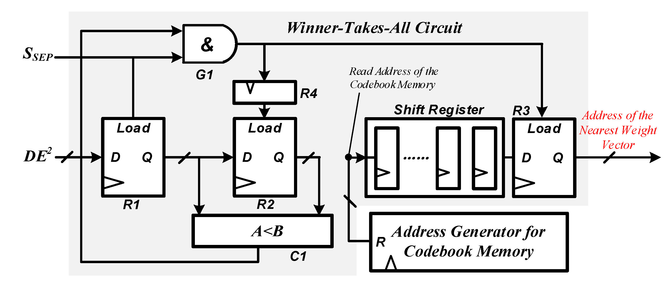
Figure 5.
A prototype of the image compression system based on the proposed vector quantizer. FPGA: field programmable gate array; LCD: liquid-crystal display; DVI: digital visual interface.
Figure 5.
A prototype of the image compression system based on the proposed vector quantizer. FPGA: field programmable gate array; LCD: liquid-crystal display; DVI: digital visual interface.

Figure 6.
Visual quality comparisons between the compressed images for (a) Lena, (b) Peppers, and (c) Tank. The images in each row from the left to the right are the compressed images as the sizes of pixel-block are 4 × 4 (the corresponding compression ratio is 16), 4 × 8 (the corresponding compression ratio is 32), 8 × 8 (the corresponding compression ratio is 64), 8 × 16 (the corresponding compression ratio is 128), and 16 × 16 (the corresponding compression ratio is 256), respectively.


Figure 7.
PSNR (peak signal-to-noise ratio) vs. compression ratio for Lena, Peppers, Tank.

Figure 8.
MCPS (million connections per second) of the proposed vector quantizer with different compression ratio and parallel block number.
Figure 8.
MCPS (million connections per second) of the proposed vector quantizer with different compression ratio and parallel block number.

Table 1.
Hardware resource usages of the proposed vector quantizer.
| Resources | Used | Available | Utilization |
|---|---|---|---|
| Combinational ALUTs | 74,368 | 182,400 | 40% |
| Memory ALUTs | 0 | 91,200 | 0% |
| Total registers | 62,784 | N/A | N/A |
| Total block memory bits | 36,864 | 14,625,792 | <1% |
| DSP block 18-bit elements | 0 | 1288 | 0% |
| Total PLLs | 1 | 8 | 12.5% |
ALUT: adaptive look-up table; DSP: digital signal processor; PLL: phase-locked loops; N/A: not applicable.
Table 2.
Comparison results with the previous VQ (Vector quantization)-based image compression circuits.
Table 2.
Comparison results with the previous VQ (Vector quantization)-based image compression circuits.
| Design | [11] | [13] | This Work | |
|---|---|---|---|---|
| k = 16 | k = 32 | |||
| FPGA family | Virtex II | Virtex IV | Stratic IV | |
| Compression ratio (CR) | 16 (Fixed) | 3 (Fixed) | ≥16 (Adjustable) | |
| PSNR (dB) | 31.28 | 37.10 | 30.69 (CR = 16) | |
| Frequency (Hz) | 71.43 M | 19.6 M | 80.1 M | 79.8 M |
| MCPS | 11,026 | N/A | 14,247 @ CR = 16 | 21,845 @ CR = 16 |
| LUTs | 40,280 | 17,6130 | 37,214 | 74,368 |
| Compression speed (frames/s) | 160 | 107 | 212 @ CR = 16 275 @ CR = 64 296 @ CR = 256 | 324 @ CR = 16 500 @ CR = 64 585 @ CR = 256 |
FPGA: field programmable gate array; PSNR: peak signal-to-noise ratio; MCPS: million connections per second; LUT: look-up table.
© 2017 by the authors. Licensee MDPI, Basel, Switzerland. This article is an open access article distributed under the terms and conditions of the Creative Commons Attribution (CC BY) license (http://creativecommons.org/licenses/by/4.0/).
Share and Cite
MDPI and ACS Style
Huang, Z.; Zhang, X.; Chen, L.; Zhu, Y.; An, F.; Wang, H.; Feng, S. A Hardware-Efficient Vector Quantizer Based on Self-Organizing Map for High-Speed Image Compression. Appl. Sci. 2017, 7, 1106. https://doi.org/10.3390/app7111106
AMA Style
Huang Z, Zhang X, Chen L, Zhu Y, An F, Wang H, Feng S. A Hardware-Efficient Vector Quantizer Based on Self-Organizing Map for High-Speed Image Compression. Applied Sciences. 2017; 7(11):1106. https://doi.org/10.3390/app7111106
Chicago/Turabian StyleHuang, Zunkai, Xiangyu Zhang, Lei Chen, Yongxin Zhu, Fengwei An, Hui Wang, and Songlin Feng. 2017. "A Hardware-Efficient Vector Quantizer Based on Self-Organizing Map for High-Speed Image Compression" Applied Sciences 7, no. 11: 1106. https://doi.org/10.3390/app7111106
Note that from the first issue of 2016, this journal uses article numbers instead of page numbers. See further details here.