Article

Tire-Pavement Friction Characteristics with Elastic Properties of Asphalt Pavements

1
National and Regional Engineering Lab for Transportation Construction Materials, College of Civil Engineering, Chongqing Jiaotong University, 66 Xuefu Ave, Nanan Qu, Chongqing 400074, China
2
Highway School, Chang’an University, Middle-Section of Nan’er Huan Road, Xi’an 710064, China
3
Chongqing Jianzhu College, 857 Lihua Ave, Nanan Qu, Chongqing 400072, China
*
Authors to whom correspondence should be addressed.
Appl. Sci. 2017, 7(11), 1123; https://doi.org/10.3390/app7111123
Submission received: 16 September 2017 / Revised: 26 October 2017 / Accepted: 26 October 2017 / Published: 1 November 2017
(This article belongs to the Special Issue Advanced Asphalt Materials and Paving Technologies)

Abstract

:
The skid-resisting performance of pavement is a critical factor in traffic safety. Recent studies primarily analyze this behavior by examining the macro or micro texture of the pavement. It is inevitable that skid-resistance declines with time because the texture of pavement deteriorates throughout its service life. The primary objective of this paper is to evaluate the use of different asphalt pavements, varying in resilience, to optimize braking performance on pavement. Based on the systematic dynamics of tire-pavement contact, and analysis of the tire-road coupled friction mechanism and the effect of enlarging the tire-pavement contact area, road skid resistance was investigated by altering the elastic modulus of asphalt pavement. First, this research constructed the kinetic contact model to simulate tire-pavement friction. Next, the following aspects of contact behaviors were studied when braking: tread deformation in the tangential pavement interface, actual tire-pavement contact in the course, and the frictional braking force transmitted from the pavement to the tires. It was observed that with improvements in pavement elasticity, the actual tire-pavement contact area increased, which gives us the ability to effectively strengthen the frictional adhesion of the tire to the pavement. It should not be overlooked that the improvement in skid resistance was caused by an increase in pavement elasticity. This research approach provides a theoretical basis and design reference for the anti-skid research of asphalt pavements.

1. Introduction

Skid resisting performance is the primary factor affecting traffic safety, specifically during vehicle braking where the anti-skid deficiencies found in pavement will prolong braking time and increase braking distance [1]. Due to this concern, highway authorities and researchers have been exploring the anti-skid properties of pavement through the frictional contact analyses of three key factors.
The first factor is water. In the early 1960s, Horne and Dreher 1963 [2] put forward the famous National Aeronautics and Space Administration (NASA) hydroplaning equation, which is used to calculate the hydroplaning speed of a tire. Later, Martin 1966, Eshel 1967, and Tsakonas et al. 1968 [3,4,5] also simulated the hydroplaning of a tire, but in only two dimensions. In the following thirty years, both the NASA equation and the two-dimensional contact model were promoted by Horne et al. 1986 [6] on the applicable conditions and accuracy. In the 21st century, a three-dimensional frictional model of inflated tire and rigid pavement contact, simulating moist conditions, was developed by G.P. Ong et al. 2007, 2008, 2010, 2012 [7,8,9,10]. With this model, the degradation mechanism of wet-pavement skid resistance and the subsequent effects of tire slip velocity on rigid pavement under different degrees of wetness were examined.
The second factor is the frictional property of tire rubber. The friction between tire and pavement is mainly determined by adhesive and hysteretic friction. Hysteric friction is enhanced with rise in temperature. For this analysis, K.A. Grosch 2001 [11] chose to use the rubber friction model based upon the tire rubber’s viscoelasticity. Coupling thermos-mechanics with the finite element method, Srirangam and Anupam 2013 [12,13] estimated the variations in hysteretic friction during tire-pavement contact due to differences in temperature. This estimation was calculated by simulating a tire rolling on rigid pavement in CAPA-3D (developed and dated by the group of Mechanics of Infrastructure Materials at Delft University of Technology, The Netherlands) Finite Element system.
The third final component in exploring the anti-skid properties of pavement is the surface texture of the pavement. Both the macro-texture and micro-texture are typically used to represent the skid resistance of pavement. The correlation between pavement texture and skid resisting ability are often evaluated via various test methods (Forster, S. W. 1990, Burak Sengoz 2014, Malal Kane 2015 [14,15,16]). For instance, Srirangam and Anupam 2013 [12,13] captured morphological data reflecting the surface of asphalt pavement through X-ray tomography. Furthermore, they reconstructed the texture of the pavement in CAPA-3D and analyzed their simulation of the kinetic contact of tires rolling on the rough, rigid-pavement [17].
After analyzing the aforementioned literature, we found that research on skid resistance primarily focuses on the macro or micro-texture of the pavement, by which the anti-skid property could be achieved. In addition, there are two methods to model asphalt pavement in the finite element analysis. One approach is modeling the pavement as a flat rigid surface, while the other one is an analytical rigid body with a macro-texture surface. It is apparent that both means of modeling consider the asphalt pavement as a rigid body, disregarding its elasticity.
In the field of terrain vehicle mechanics, the fundamental source of vehicle braking is the friction between the tires and pavement. As illustrated in Figure 1a, the pedal force Fp is delivered to the wheel brake the moment the driver steps on the pedal, forming the frictional moment Tμ opposite the momentum of the tire. This moment could be regarded as the circumferential component Fμ, which is applied to the tire-pavement contact region to prohibit the rotation of the tire. Simultaneously, the pavement generates a reactive force on the vehicle, namely, the ground braking force Fb, which ultimately slows down vehicles or even allows them come to a complete halt. In other words, Fb is equal to Fμ, which is also comparable to Tμ divided by the tire radius r. Nevertheless, restrained by the upper limit of the adhesive force Fφ (the maximum braking force Fbmax is equal to Fφ), Fb will not rise as soon as it runs up to Fφ (Figure 1b). Furthermore, from the aspect of tribology, it can be concluded that physical properties of the interface, such as variations in material stiffness, will result in the change in contact area, which will then have an influence on the frictional force (Chengtao Wang 2002 [18]). Eventually, the actual tire-pavement area will vary as a result of pavement characteristics such as the diversification of recoverable resilient. Accordingly, the force of adhesion Fφ will also change, accounting for differentiation in the tire-oriented pavement braking function (Jide Zhuang 1986 [19], Liangxi Wang 2008 [20]).
Data produced from the uniaxial compressive strength testing of pavement with normally structured the asphalt specimens is generally above 1000 MPa (You et al. 2009 [21]; Goh et al. 2011 [22]); a value seemingly much higher than the longitudinal tire stiffness. Therefore, in consideration of time expended in a simulated calculation, the deformation of asphalt pavements is usually ignored in modeling (Srirangam 2013 [13], Hao Wang 2014 [23]). In other words, the pavement is defined as a rigid body in simulations. Nonetheless, along with the diversification of paving materials, the elastic modulus of asphalt mixtures also varies significantly. For instance, dry process crumb rubber modified (CRM) asphalt mixtures, which plays an indispensable role in noise reduction and the de-icing (Chunxiu Zhou 2006 [24], Xudong Wang 2008 [25]), is characterized by its remarkable elasticity. In addition, a high content of crumb rubber, which is added to asphalt mixtures, usually reduces the mixture modulus to half of that of the original (Lili Yao 2012 [26]). Such elasticity has the capacity to facilitate the resilience of CRM asphalt mixtures, which are characterized by a large elastic deformation under external loading conditions and a dramatic return to its original shape immediately after the removal of the load in comparison to that of ordinary asphalt mixtures (Miao Yu, Guoxiong Wu 2014 [27,28,29]). In view of the distinctly narrowed gap of moduli between tires and resilient pavements such as CRM asphalt pavement, the precision of the simulation will inevitably decrease if the resilient pavement still needs to be modeled as a rigid body. Furthermore, according to past literature, the actual stiffness of asphalt pavement is not used in tire-pavement coupled modeling, meaning that the impact of pavement stiffness on tire-pavement friction has not been examined yet (Hao Wang 2014 [23], Reginald B. Kogbara [30], Shahriar Najafi [31]).
Based on the above background research, the primary objective of this paper is to evaluate the effect of different asphalt pavements of variable resilience on braking performance on pavement. This goal was initially achieved using a 3-D finite tire-asphalt pavement interaction model. By adjusting parameters such as tire pressure and the elastic modulus, behaviors of the dynamic tire-pavement contraction were studied by discussing the varying features of tire-pavement contact such as tread deformation in the tangential interface, actual contact area between the tire and the pavement surface course, and the braking force supplied by the pavement to the tires.

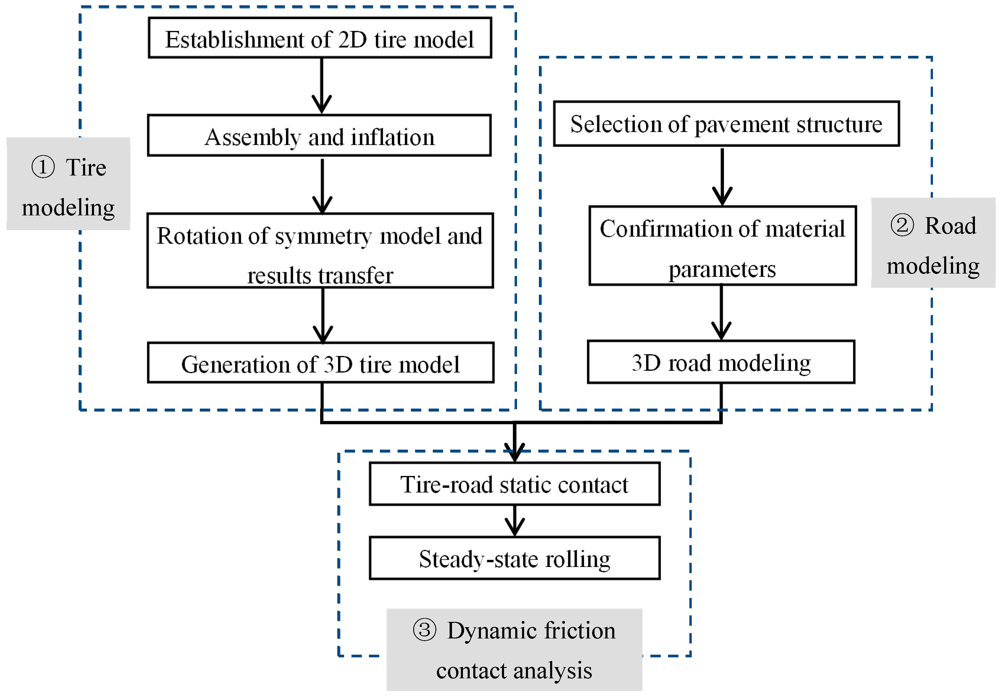
2. Establishment of Tire-Pavement Frictional Contact Simulation Model

To begin, the traffic load and vehicle braking were simulated by establishing 3D tire models. Next, a road model was built by adopting the pavement structure of “asphalt surface layers + cement stabilized macadam base + lime-ash cushion + subgrade.” Meanwhile, frictional contact laws were defined in ABAQUS (a commercial program of Finite Element Analysis, produced by Dassault Systèmes® Johnston, RI, USA, founded in 1978) , and subsequently, the contrastive analysis of kinetic friction between the tire and the flexible pavement surface was conducted on specimens created with various combinations of paving material parameters.
The simulation model of the dynamic friction due to tire-pavement contact was created in a three-step process shown in Figure 2. Specifically, a 3D model was built, then the steady state of the kinetic contact was analyzed in ABAQUS/Standard solver based upon static contact.

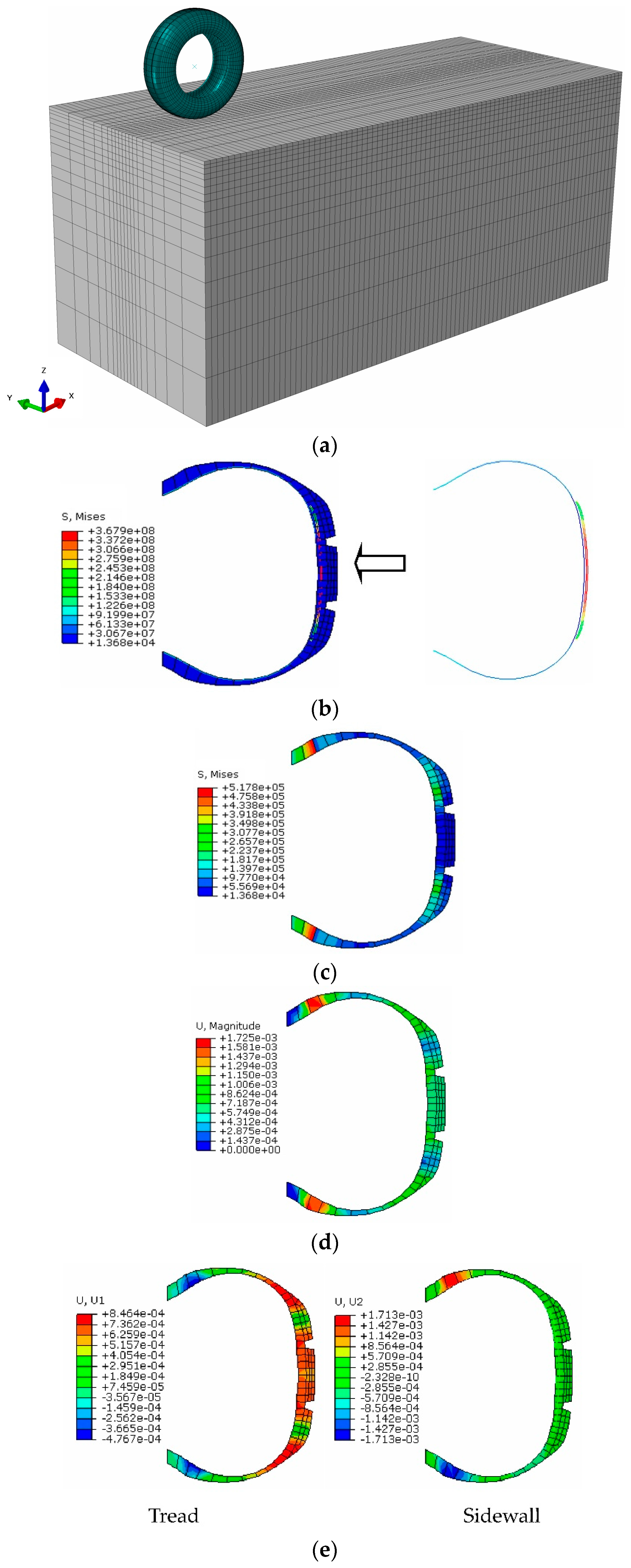
2.1. Establishment of 3D Model for Grooving Radial Tires

Referring to ‘Steady-state rolling analysis of a tire’ of ABAQUS 6.10 Example Problem Manual [32], three steps were used to create the 3D models of grooving radial tires: (1) simplification before modeling; (2) importing a 2D tire cross-sectional model into ABAQUS; and (3) 3D model generation of pneumatic tires:
(1) Simplification before Modeling. In order to improve the computational efficiency, the total cross section of a 2D model was drawn using CAD2014 software (developed by Autodesk corporation in San Rafael, CA, USA, founded in 1982), which was simplified according to the following:
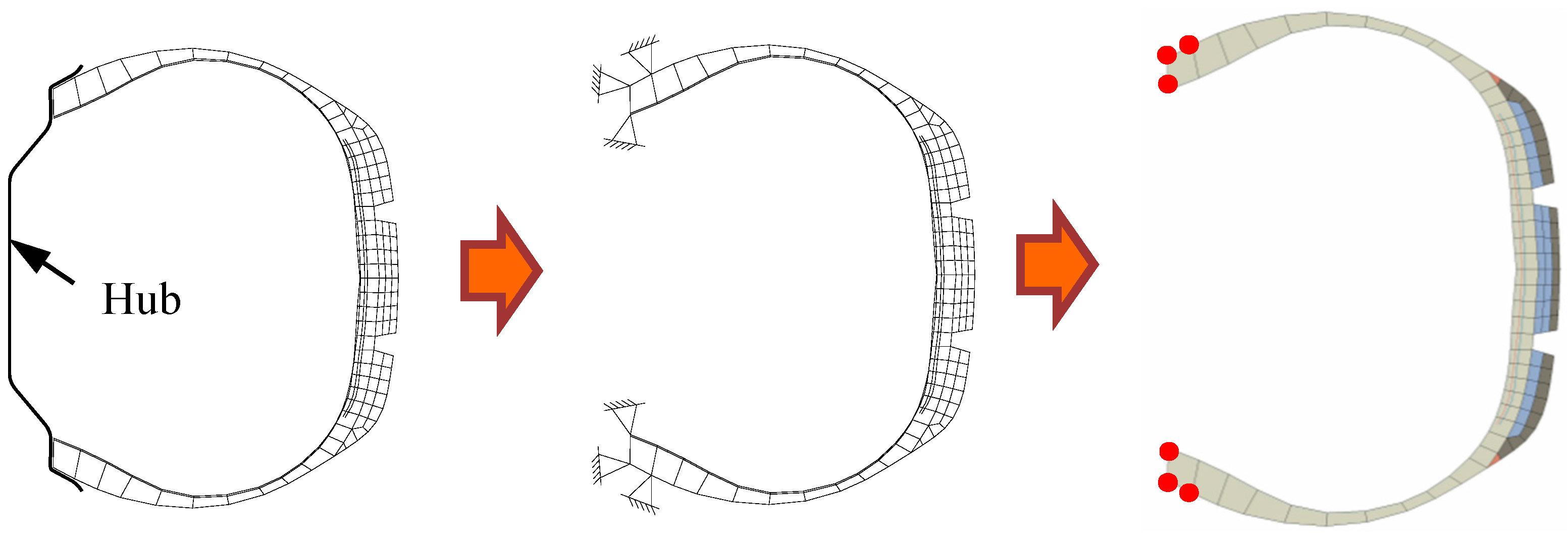
  • Reduce the poor shape of the cross-sectional element;
  • Simplify the contact constraint between the bead chafer and the wheel hub (see Figure 3 for details. Next, simplify the wheel hub as a rigid constraint element, which shares a node with the tire bead);
  • Use the rebar elements to simulate the tire’s steel cord and inner liners.
(2) Importing a 2D Tire Cross-sectional Model into ABAQUS. To start, the simplifed 2D tire cross-sectional model was imported into ABAQUS. Subsequently, the steel cord of the tire and inner liners were defined as the primary tire materials.
1 Rubber materials
This study aims to establish a 3D model for a 175SR14 groove tire. The Neo-Hooken model was selected to describe the constitutive relationship of the super elasticity (Yanfeng Zhu 2006 [33], Yongguan Wang 2007 [34]). A Prony series is adopted to define the viscoelasticity of the rubber in ABAQUS. Both the above parameters were calibrated to acquire deflection values close to experimental measurements. Please see Table 1 for the relative tire rubber parameters (the simulated and tested datum).
2 Steel cord-rubber composite materials
Steel cord-rubber composite materials are usually composed of cords in different orientations. The nonlinearity of rubber results in anisotropy and nonlinearity of the steel cord-rubber composite material in tires. Therefore, a rebar layer was applied to simulate the composite materials layer. First, the steel cord and inner liner were defined in ABAQUS and secondly, the membrane element that represents the steel cord in the defined steel cord layer was embedded. Meanwhile, the membrane element representing the inner liner in the inner rubber layer was also embedded to accomplish the simulation of the steel cord and inner liner. The parameters of the steel cord (Belt-1, Belt-2) and inner liner (Carcass) were defined successively (see Table 2).
(3) 3D model generation of pneumatic tires.
Definitions the section unit type, mesh partition, and 2D tire inflation (tire pressure of 250 kPa) were accomplished in this phase. Furthermore, the 2D tire section was used to generate a 3D tire model. Therefore, The final step in tire modeling was to transform the 2D section property into a 3D tire model.

2.2. Pavement Structure Modeling

2.2.1. Pavement Structure Setting

The road asphalt pavement structure was adopted as 4 cm + 6 cm + 8 cm, as illustrated in Table 3, which is commonly used in China’s major highways. The thickness of the base and the bed course was 18 and 31 cm respectively. A displacement restriction is imposed on both longitudinal ends in the x direction and transverse ends in the y direction of the pavement; the consolidation constraint was applied to the bottom surface separately. Moreover, the entirety of the 3D pavement model was divided according to the principle that meshing density should be cut from the region of tire-pavement contact to the boundaries in every direction.

2.2.2. Design of Road Pavement Materials

In attempt to ameliorate the enhance of asphalt pavement, several authors found that adding crumb rubber into the asphalt mixture by dry process can improve the overall elastic deformation capacity, thus increasing the tire grip (Xudong Wang 2008 [25]) and strengthening braking performance of the pavement (Chengtao Wang 2002 [18], Jide Zhuang 1986 [19], Liangxi Wang 2008 [20]). Therefore, based on the research findings of Miao Yu and Guoxiong Wu 2014 [27,28,29], the asphalt specimens with 0%, 4% and 5.5% crumb rubber content were fabricated (below, the corresponding pavements are functionally named as low-E, med-E, and high-E in sequence). The crumb rubber content herein represents the percentage of crumb rubber volume accounts for total aggregate volume of asphalt specimens. Furthermore, the volumetric parameters were measured for the purpose of comparison between the effects of different pavement properties on tire brake performance. Table 3 outlines the pavement structure and relevant material parameters. Besides, data of elasticity modulus in this table represents uniaxial compressive modulus of resilience, originating from uniaxial compression test at 20 °C.

2.3. Tire-Flexible Pavement Frictional Contact Simulation

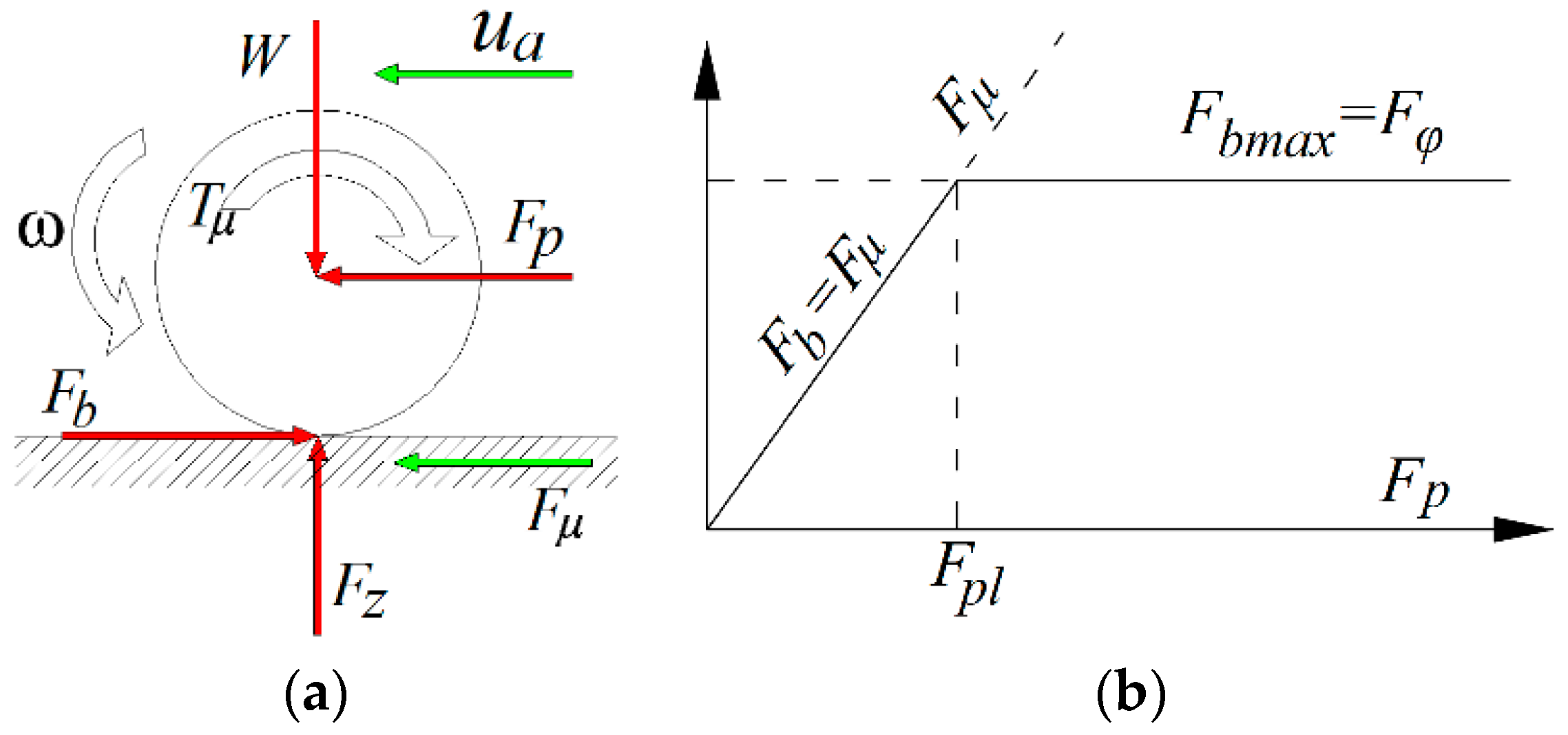
2.3.1. Definition of the Tire-Pavement Frictional Contact in ABAQUS

The following parameters facilitating frictional contact and the subsequent tire-pavement interaction analysis (Y Liu et al. 2015 [35]) were defined.
① Slip ratio σx (Equation (1)) is a representation of the slip status during the tire rolling phase,
σ x = u a r e f f · ω w u a × 100 %
where
  • ωw—the rotational angular velocity of the wheel hub; rad/s
  • reff—the effective radius of the wheel; m
  • ua—the actual longitudinal velocity of the tire; m/s
② The static friction coefficient μ (Equation (2)) is defined as the friction between the tire and pavement in the initial contact phase (the tire is about to slide), in which the tire velocity is zero
μ   =   F / N
where
  • F—the tangential force between tire and pavement contact
  • N—the normal force, perpendicular to the contact between tire and pavement
③ The braking force coefficient φb (Equation (3)) describes the braking ability of asphalt pavements. In addition, φb is the Skid Number (SN), representing tires-pavement contact when braking; a larger φb will account for a higher braking efficiency of the tires.
φb = 100 × Fx/Fz
where
  • Fx—the horizontal braking force of the pavement against the tire at the contact region
  • Fz—the upper load borne by the tires
④ In order to facilitate comparative analysis, the actual longitudinal velocity of the center of the tire was set at 80 km/h, and the static friction coefficient μ was 0.7 (Jide Zhuang 1986 [19], Judge, A. W. 2008 [36]).
⑤ Tire-asphalt pavement contact definition
Static contact between the tire and asphalt pavement could be modeled via two methods; displacement control and load control. In comparison to the latter, the former usually decreases calculation time and in comparison, produces more reliable results. Thus, the displacement control of the tire and pavement contact was established by applying 2 cm displacement on the rigid reference node of the tire. Secondly, the load control of the tire and pavement contact was set up, that is, causing us to remove the pre-assigned displacement and apply vertical displacement on the tire reference node with respect to the pavement. The tire-pavement static contact was determined via the two steps above. Furthermore, the tire-pavement contact was set at “hard contact” of “finite sliding”. Meanwhile, the method of combining isotropic Coulomb friction combined with the penalty function algorithm was adopted to realize the tire-pavement frictional contact simulation model in Figure 4a.

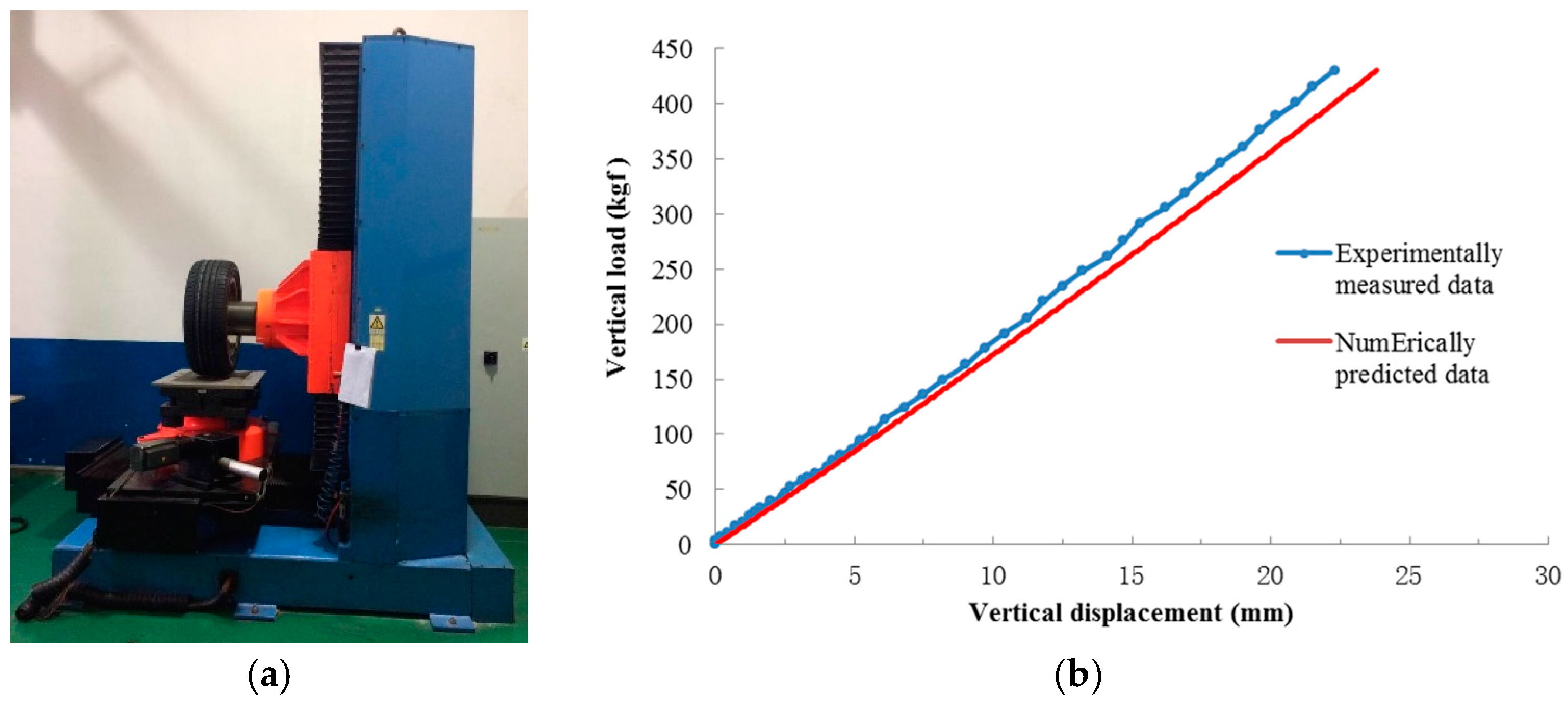
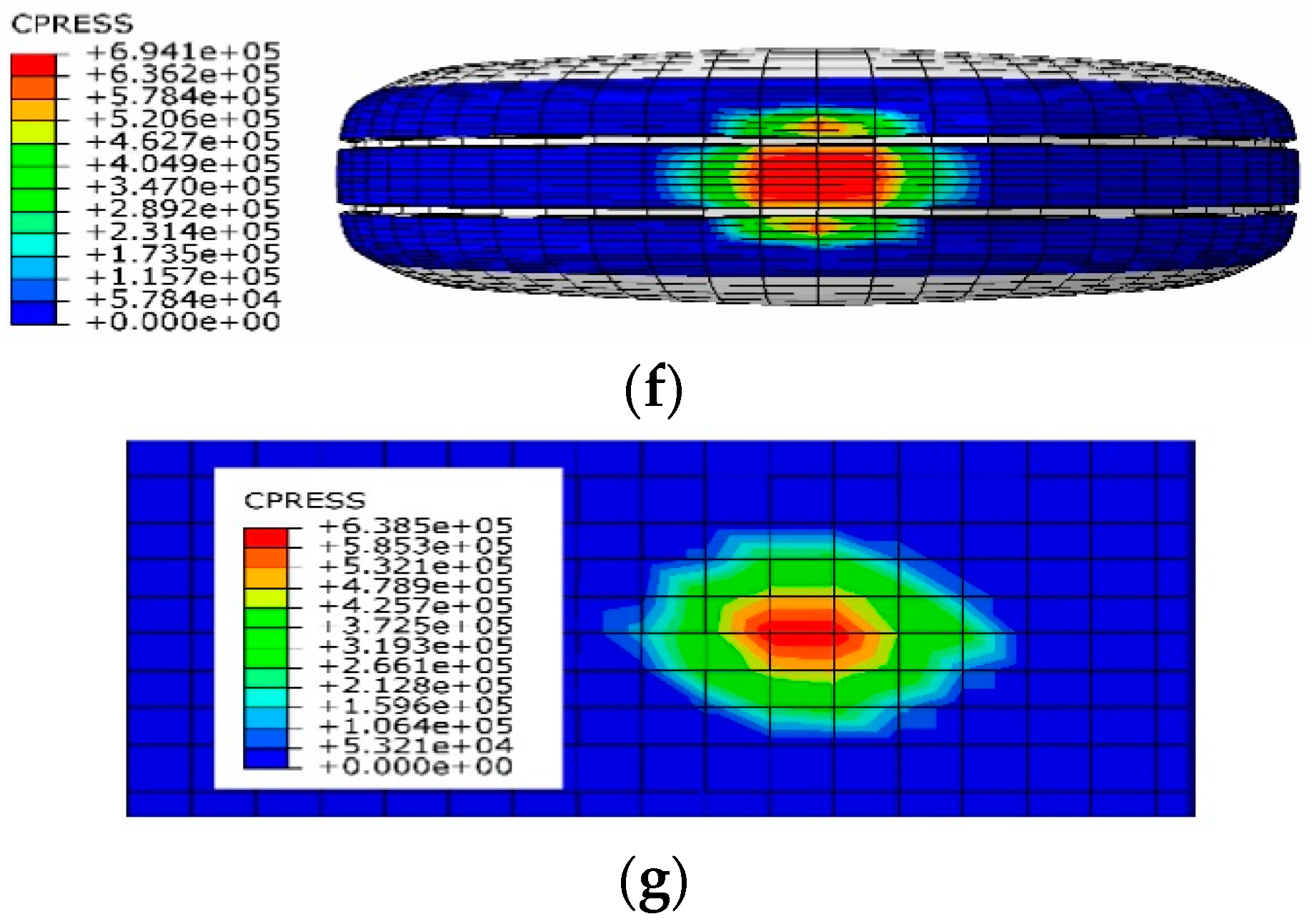
2.3.2. Validation of the 3D Model of Pneumatic Tire-Asphalt Pavement Contact

The complicated nonlinear characteristic of the kinetic contact between tire and pavement will have a major effect not only on the convergence of both the implicit and explicit analyses, but also on the accuracy and computation time of the above analyses. Therefore, before carrying out the dynamic analysis of the tire-pavement contact, it is necessary to successively validate the simulation of the pneumatic tire and its static contact with the pavement.
① Tire inflation
Figure 4b shows the Mises equivalent stress nephogram of the 2D tire cross section. It can be seen that the steel cord bears the primary load of the inner tire after inflation. While the whole tire is under tension, the maximum stress lies in the middle of the steel cord found in the tread. To facilitate investigation of the stress-strain characteristics found in the tire rubber materials, the inner liner of the tire was removed.
It can be observed in Figure 4c,d that both the maximum values of the Mises stress and the total strain appeared near the hub constraints when assembled with a wheel hub and bearing inflation pressure. In contrast, when the steel cord bore the maximum tensile stress, the tread rubber presented relatively smaller stress without the self-weight load. As depicted in Figure 4d, it was found that the consolidation constraints contributed to zero displacement around the wheel hub, whereas the aligned regions showed higher stress. In addition, the tread showed lower Mises stress, accounting for a larger deformation of the rubber materials near the wheel hub of the sidewall. Figure 4e depicts the deformation nephogram of the inflated tire along its tread and sidewall directions. It is noted that the deformation in 1 orientation (U1) was primarily created in the connecting region of the sidewall and shoulder. On the other hand, the deformation in 2 directions (U2) was always concentrated on the sidewall near the hub. It can be concluded that, from the above analysis of Figure 4c–e, the principle deformation region lied in the sidewall of tires, in accordance with practical conditions.
② Static tire contact conditions
Under the tire-pavement contact conditions shown in Figure 4f,g, tire grooves accounted for the concentration of the tire-pavement ground pressure, which lied mainly within the longitudinal pattern rather than out of the grooves. Accordingly, the contact pressure on the pavement surface was also gathered in the middle of the contact region.
A photograph of the tire’s static loaded test performed by UTTM Stiffness Tester (Testing Service GmbH, Aachen, North Rhine-Westphalia, Germany), is presented in Figure 5a. Comparison of the test data of load-tire vertical deformation, size of contact region as well as the actual contact area with the relative numerically predicted results are shown in Figure 5b and Table 4. It can be seen that the predicted results seem very close to the results of the lab experiments.

3. Simulation Analysis of Tire-Asphalt Pavement Frictional Contact

3.1. Simulation Conditions Design of the Tire-Asphalt Pavement Frictional Contact

It is well known that the braking force (coefficient) changes with variations in slip ratio. At the early stage of the tire braking procedure, the adhesive force, Fφ, is proportional to the slip ratio. However, because the pavement braking force, Fb, is restrained by the adhesive force, Fφ, Fb will stop rising upon reaching the maximum Fφ value, and the slip ratio will continue to increase. Therefore, it is relevant to note that if pavement could provide tires with a greater adhesive force, Fφ, tires will receive a greater braking force, Fb, from the pavement, facilitating the vehicle braking efficiency. Thus, this study analyzes elasticity’s contribute to tire braking efficiency on pavement using various slip ratios. The three slip ratios listed in Table 5 were used to analyze the frictional contact of tire-pavement.

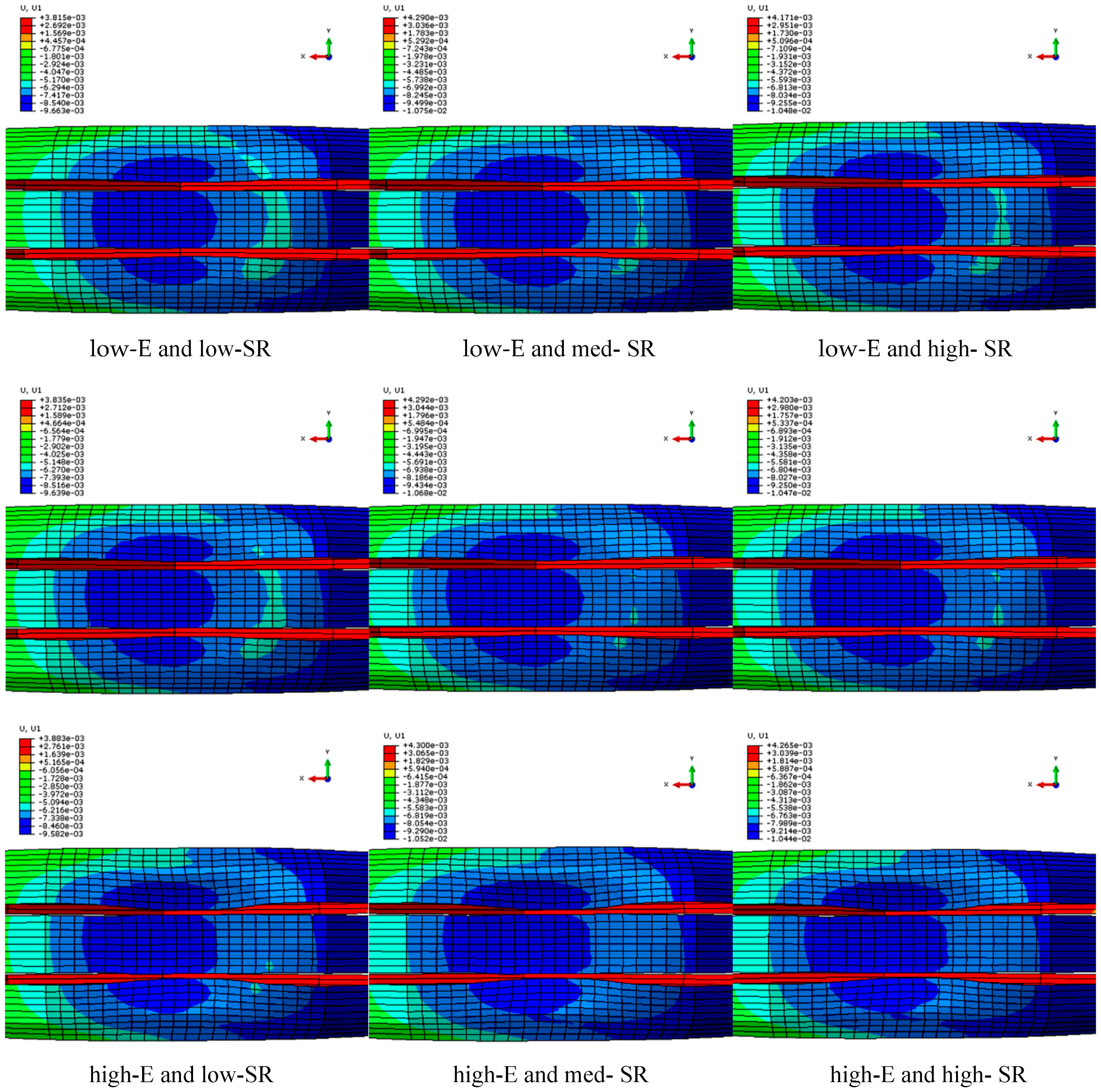
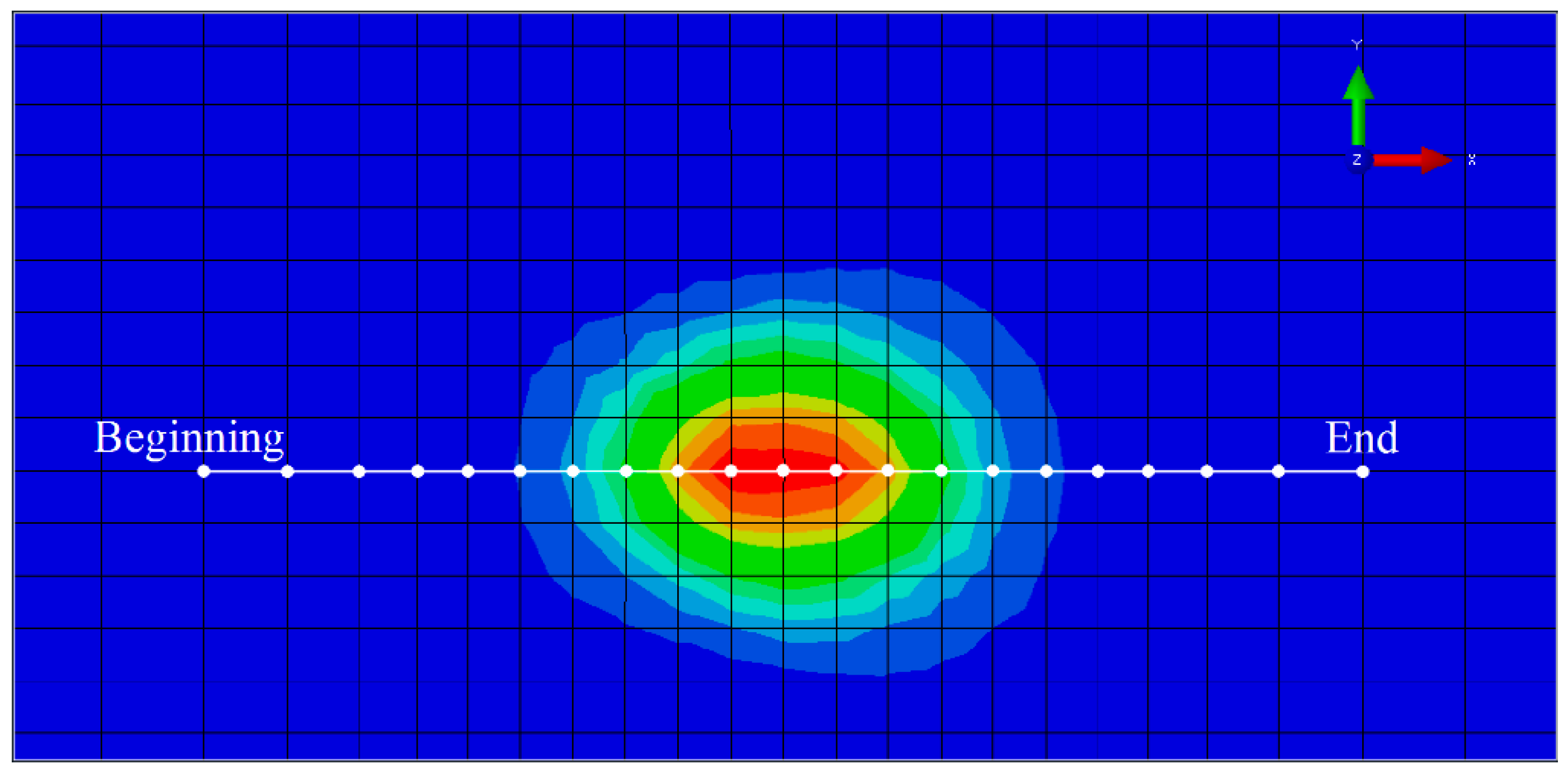
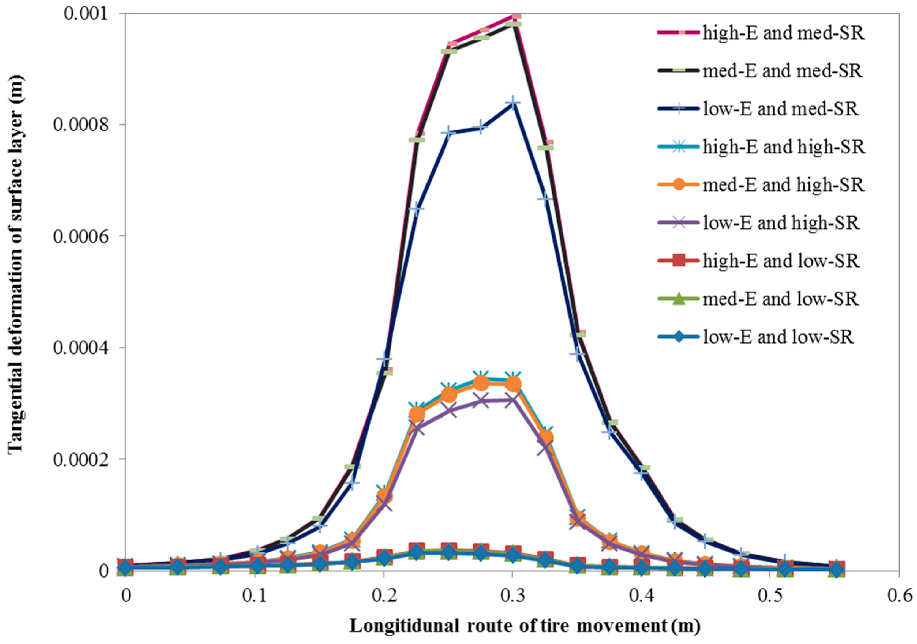
3.2. Tread Deformation

Tire braking behavior has a distinct impact on tangential tire deformation. Therefore, the tangential deformation was examined to investigate tire-pavement frictional behaviors.
Figure 6 depicts tangential deformation of the tire tread along vehicle’s direction of motion. It can be inferred from the nephogram that:
When the slip ratio is only 7%, the tread’s tangential deformation is insignificant. Nevertheless, as the pavement’s elasticity is improved, the deformed area has become longer and wider, extending to the marginal region of sidewall in the direction of the tire’s motion. These phenomena account for the enlargement of the tire-pavement contact area; the effect tire adhesion on highly elastic pavement is a superior braking agent in comparison to that of common pavement with no crumbed rubber additives.
Secondly, under each of the nine conditions, the direction of tread deformation is opposite to the tire’s motion path. Under conditions of high-E, the tread deformation area is significantly larger in comparison to conditions of low-E and med-E. This pattern is also found in the slip direction of the tire head’s mesh. The above findings explain that while stiffness decreased and elasticity improvements were made in the paving materials, the deformity and braking force applied to the tires increases. Therefore, the tire-pavement contact area enlarges with elasticity. This trend indicates that appropriate decreases in pavement stiffness could facilitate enough tire-pavement contact to enhance tire adhesion, improving brake efficiency.
By examining the tread deformation along the direction of tire movement under 10% and 14% slip ratio, we see that when the slip ratio is 14%, the tread deformation slightly decreases, indicating that tire adhesion does not always improve with the increased slip ratio. This change agree with the law that as the slip ratio is between 10% and 15%, the tire braking force coefficient will reach the maximum value [18].

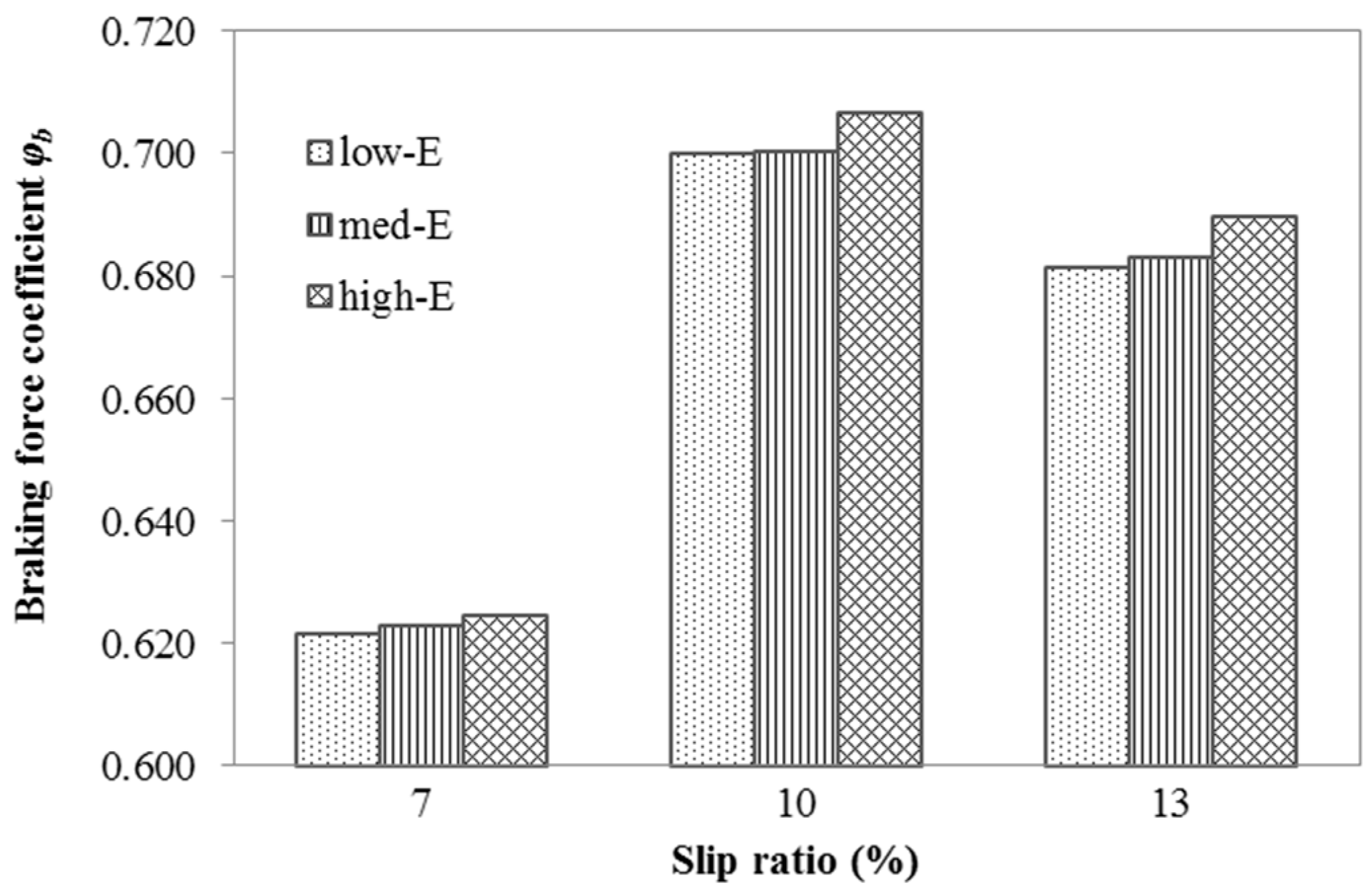
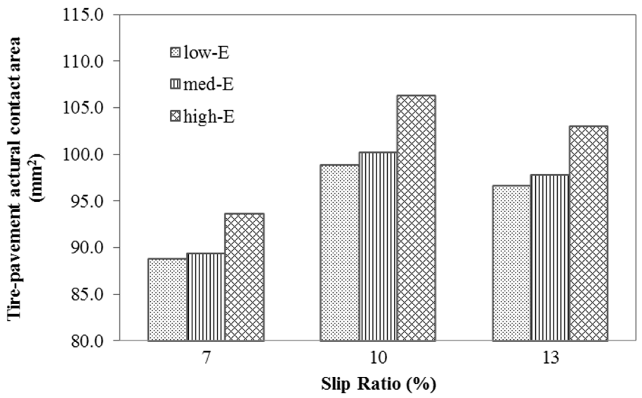
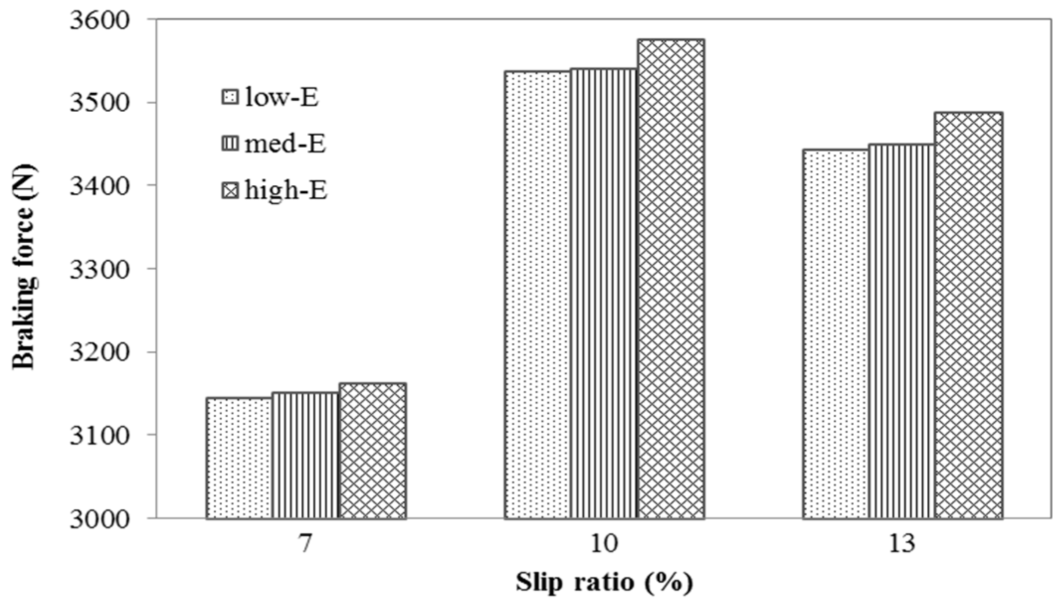
3.3. Pavement Braking Effect

Tire slip ratio is directly correlated to the tangential deformation found in the tire-pavement contact zone. Therefore, the tangential displacement of the pavement surface, along the direction of tire movement (Figure 7), is primarily used to investigate pavement deformation under various slip ratios. Figure 8 illustrates the pavement’s tangential deformation response under three types of tire slip ratios. The comparison shows that pavement tangential deformation varies most significantly with the alternation of slip ratios. For example, consider a 7% slip ratio; the tangential deformation is generally no more than 0.1mm, whereas the deformation could reach 1mm as the slip ratio reaches 10% or higher. The figure also depicts the impact of pavement modulus on tangential interaction, which should not be ignored. It can be observed that in highly elastic pavement (high-E), the tangential resistance to tire rolling is more significant than that of other pavements (low-E and med-E) under the same slip ratio. Therefore, it can be concluded that changes in tire-pavement tangential behavior caused by slight alterations in pavement resilience can be neglected due to their negligibility in comparison to slip ratio.
Figure 9 and Figure 10 respectively present the correlation of contact area and pavement braking force under different slip ratios. As the slip ratio increases from 7 to 10%, the contact area enlarged, intensifying the tire-pavement friction, causing an upward trend in the braking force applied by the pavement. When the slip ratio raised from 10 to 14%, the contact area began to reduce, accounting for degradation of the tire adhesion effect. According to Figure 6, the braking force also declined along with increasing slip ratio. The two figures illustrate that tire-pavement contact area is related to pavement braking force. In other words, tire adhesion has a substantial impact on the braking force applied by asphalt pavements.
Figure 11 also shows that the braking force coefficient of pavement does not always enlarge with increases in slip ratio; this coefficient will decrease after reaching its peak value. Using the tire modeled in this research, it was found that pavement type has the most significant braking impact at a slip ratio value near 10%. Furthermore, with reduction in contact area, the effect of pavement type on braking diminished with slip ratios greater than 10%. However, it can be observed that for the most elastic pavement (high-E), the corresponding braking force coefficient is greater than the other two types of less elastic pavement. As the slip ratio was further improved, the braking effect of the high elastic pavement began to degrade, nonetheless, this pavement’s braking effect is superior to that of the other pavements. Therefore, it can be concluded that the enhancement of pavement elasticity will give rise to the braking efficiency of the tires under different slip ratios.

4. Conclusions and Discussion

To increase brake efficiency and enhance driving safety, the 3D dynamic frictional contact model was created to conduct a reliable analysis of tire-pavement friction. Through this method, the following conclusions were determined.
First: increasing pavement elasticity could enlarge the tire-pavement actual contact area, providing tires with stronger grip.
Second: slip ratio has the most significant impact on frictional behaviors during tire-pavement contact. However, under the same slip ratio, high elasticity significantly interferes with tire rolling in comparison to pavements of ordinary elasticity.
Third: the braking force coefficient can be slightly raised by the distinct improvement of pavement elasticity. However, braking distance is sensitive to tiny variations in this coefficient, allowing anti-skidding improvements to be made in asphalt by remarkably increasing the pavement’s elasticity.
Pavement skid resistance, coupled with vehicle, tire and pavement surface layer, is a problem that includes factors such as aggregate hardness, pavement surface texture and stiffening of paving materials. Moreover, analyzed from the aspect of the tire, this issue also investigated the effect of tire inflation pressure; tread pattern and the physical and mechanical properties of tread rubber materials. In addition, investigated from the angle of tire-pavement coupling, it is a systemic problem that incorporates tire slip ratio, tire-pavement contact behavior, and even the appropriate friction law. Conventional methods focus upon macro and micro texture effects on the frictional properties of the tire, to decrease the skid resistance of asphalt pavement. Investigating the changes in skid resistance caused by altering the recoverable resilient deformation property of pavement is a new approach to increasing driver safety. This method can be used to facilitate tire grip and enhance braking performance. This paper investigates pavement skid resistance from the aspect of paving materials’ moduli; tire-pavement friction coupled with pavement texture, heat transfer by coupled frictional behaviors, stiffness modulus, and water film effects will be discussed in future research.

Acknowledgments

This work is financially supported by the 2014 Chongqing Higher Education Institution’s Excellent Achievements Program (Major Project) (Theme: Warm mix, semi-flexible compound pavement Technology (KJZH14104)), 2015 Chongqing Higher Education Institution’s scientific and technological research program (Theme: Research on the skid Resistance Performance of CRM asphalt pavement based on the tire-pavement kinetic friction test system (KJ1500508)), and the 2016 National Natural Science Foundation of China (Tire braking-oriented anti-skid mechanism and estimating model of friction coefficient of asphalt pavement, No. 51608085).

Author Contributions

Miao Yu was in charge of the whole research program; Guoxiong Wu built the trial protocol; Lingyun Kong and Yu Tang performed the experiments and data analysis. All authors discussed and contributed to the preparation and revision of the manuscript.

Conflicts of Interest

The authors declare no conflict of interest.

References

  1. Henry, J.J. Evaluation of Pavement Friction Characteristics (A Synthesis of Highway Practice); NCHRP Synthesis No. 291; National Cooperative Highway Research Program; Transportation Research Board: Washington, DC, USA, 2000. [Google Scholar]
  2. Horne, W.B.; Dreher, R.C. Phenomena of Pneumatic Tire Hydroplaning; NASA TN D-2056; National Aeronautics and Space Administration: Washington, DC, USA, 1963. [Google Scholar]
  3. Martin, C.S. Hydrodynamics of Tire Hydroplaning; Final Rep. Project B-608; Georgia Institute of Technology: Atlanta, GA, USA, 1966. [Google Scholar]
  4. Eshel, A.A. Study of Tires on a Wet Runway; Rep. No. RR67-24; Ampex Corp.: Redwood City, CA, USA, 1967. [Google Scholar]
  5. Tsakonas, S.; Henry, C.J.; Jacobs, W.R. Hydrodynamics of Aircraft Tire Hydroplaning; NASA CR-1125; National Aeronautics and Space Administration: Washington, DC, USA, 1968. [Google Scholar]
  6. Horne, W.B.; Yager, T.J.; Ivey, D.L. Recent Studies to Investigate Effects of Tire Footprint Aspect Ratio on Dynamic Hydroplaning Speed; Pottinger, M.G., Yager, T.J., Eds.; The Tire Pavement Interface, ASTM STP 929; ASTM: Philadelphia, PA, USA, 1986; pp. 26–46. [Google Scholar]
  7. Ong, G.P.; Fwa, T.F. Wet-pavement hydroplaning risk and skid resistance: Modeling. J. Transp. Eng. 2007, 133, 590–598. [Google Scholar] [CrossRef]
  8. Fwa, T.F.; Ong, G.P. Wet-pavement hydroplaning risk and skid resistance: Analysis. J. Transp. Eng. 2008, 134, 182–190. [Google Scholar] [CrossRef]
  9. Ong, G.P.; Fwa, T.F. Modeling skid resistance of commercial trucks on highways. J. Transp. Eng. 2010, 136, 510–517. [Google Scholar] [CrossRef]
  10. Fwa, T.F.; Pasindu, H.R.; Ong, G.P. Critical rut depth for pavement maintenance based on vehicle skidding and hydroplaning consideration. J. Transp. Eng. 2012, 138, 423–429. [Google Scholar] [CrossRef]
  11. Grosch, K.A. The relation between the friction and viscoelastic properties of rubber. Proc. R. Soc. Lond. Ser. A 1962, 274, 21–39. [Google Scholar] [CrossRef]
  12. Srirangam, S.K.; Anupam, K.; Scarpas, A.; Kösters, A. Influence of tire temperature increase on friction measurements-I: Laboratory tests and finite element modeling aspects. In Proceedings of the Transportation Research Board Annual Meeting, Washington, DC, USA, 13–17 January 2013. [Google Scholar]
  13. Anupam, K.; Srirangam, S.K.; Scarpas, A.; Kasbergen, C. Influence of temperature on the tire-pavement friction-II: Analyses. In Proceedings of the Transportation Research Board Annual Meeting, Washington, DC, USA, 13–17 January 2013. [Google Scholar]
  14. Forster, S.W. Pavement Microtexture and Its Relation to Skid Resistance; 151B164; Transportation Research Record; Transportation Research Board: Washington, DC, USA, 1990. [Google Scholar]
  15. Sengoz, B.; Onsori, A.; Topal, A. Effect of aggregate shape on the surface properties of flexible pavement. KSCE J. Civ. Eng. 2014, 18, 1364–1371. [Google Scholar] [CrossRef]
  16. Kane, M.; Rado, Z.; Timmons, A. Exploring the texture–friction relationship: From texture empirical decomposition to pavement friction. Int. J. Pavement Eng. 2015, 16, 919–928. [Google Scholar] [CrossRef]
  17. Srirangam, S.K.; Anupam, K.; Scarpas, A.; Kasbergen, C. Development of a thermomechanical tyre–pavement interaction model. Int. J. Pavement Eng. 2015, 16, 721–729. [Google Scholar] [CrossRef]
  18. Wang, C.T.; Yao, Z.Q.; Chen, M. Vehicle Tribology; Shanghai Jiaotong University Press: Shanghai, China, 2002; pp. 400–423. [Google Scholar]
  19. Zhuang, J. Vehicle-Terramechanics; China Machine Press: Beijing, China, 1986. [Google Scholar]
  20. Wang, L.X.; Wang, H.Y. Vehicle Dynamics; National Defence Industry Press: Beijing, China, 2008. [Google Scholar]
  21. You, Z.; Adhikari, S.; Kutay, M.E. Dynamic modulus simulation of the asphalt concrete using the X-ray computed tomography images. Mater. Struct. 2009, 42, 617–630. [Google Scholar] [CrossRef]
  22. Goh, S.W.; You, Z.; Williams, R.C.; Li, X. Preliminary dynamic modulus criteria of HMA for field rutting of asphalt pavements: Michigan’s experience. J. Transp. Eng. 2011, 137, 37–45. [Google Scholar] [CrossRef]
  23. Wang, H.; Al-Qadi, I.L.; Stanciulescu, I. Effect of surface friction on tire-pavement contact stress during vehicle maneuvering. J. Eng. Mech. 2014, 140, 04014001. [Google Scholar] [CrossRef]
  24. Zhou, C. Study on Application Technology of Rubber Particle Asphalt Mixture in Ice and Snow Region. Ph.D. Thesis, Harbin University of Industry, Harbin, China, 2006. [Google Scholar]
  25. Wang, X. The Apply Technology of the Crumb Rubber in the Asphalt and Mixture; China Communications Press: Beijing, China, 2008; pp. 167–197. [Google Scholar]
  26. Yao, L. Research on Key Technology of Granulated Crumb Rubber Anti-ice Asphalt Pavement. Ph.D. Thesis, Chang’an Universtity, Xi’an, China, 2012. [Google Scholar]
  27. Yu, M.; Wu, G. Research on the mix design of dry process crumb rubber modified asphalt mixture. J. Build. Mater. 2014, 17, 100–105. [Google Scholar]
  28. Yu, M.; Wu, G.; Zhou, J.; Easa, S. Proposed compaction procedure for dry process crumb rubber modified asphalt mixtures using air void content and expansion ratio. J. Test. Eval. 2014, 42, 328–338. [Google Scholar] [CrossRef]
  29. Yu, M. Study on the Dry Process Crumb Rubber Modified Anti-Skid Layer Based on the Tire-Road Coupling. Ph.D. Thesis, Chongqing Jiaotong Universtity, Chongqing, China, 2014. [Google Scholar]
  30. Kogbara, R.B.; Masad, E.A.; Kassem, E.; Scarpas, A.T.; Anupam, K. A state-of-the-art review of parameters influencing measurement and modeling of skid resistance of asphalt pavements. Constr. Build. Mater. 2017, 133, 330–339. [Google Scholar] [CrossRef]
  31. Najafi, S.; Flintsch, G.W.; Medina, A. Linking roadway crashes and tire-pavement friction: A case study. Int. J. Pavement Eng. 2017, 18, 119–127. [Google Scholar] [CrossRef]
  32. Koishi, M.; Kabe, K.; Shiratori, M. Tire cornering simulation using explicit finite element analysis code. J. Appl. Polym. Sci. 2000, 78, 1566–1572. [Google Scholar] [CrossRef]
  33. Zhu, Y.; Liu, F.; Huang, X.; Li, L. Constitutive model of rubber materials. Rubber Ind. 2006, 53, 119–125. [Google Scholar]
  34. Wang, Y.; Li, X.; Huang, Y. Selection for constitutive model in rubber calculation. The chemical industry and engineering society of China. In Proceedings of the 4th Seminar China Rubber Products, Zhuzhou, Hunan, China, 17 November 2007; pp. 443–449. [Google Scholar]
  35. Liu, Y.; You, Z.P.; Yao, H. An idealized discrete element model for pavement-wheel interaction. J. Mar. Sci. Technol. 2015, 23, 339–343. [Google Scholar]
  36. Judge, A.W. Automobile engines. In Theory, Design, Construction, Operation, Testing and Maintenance; Hervey Press: Hervey, Australia, 2008. [Google Scholar]
Figure 1. Principles of braking force. (a) Principles of braking force; (b) Relationship of Fμ, Fb and Fφ during braking.
Applsci 07 01123 g001
Figure 2. 3D Tire-road contact modeling steps in ABAQUS.
Applsci 07 01123 g002
Figure 3. Simplification of contact conditions between tire bead and wheel hub.
Applsci 07 01123 g003
Figure 4. Stress and strain nephogram of the 3D model of pneumatic tire-asphalt pavement contact. (a) 3D Tire-pavement contact model; (b) Mises equivalent stress nephogram of the inflated tire; (c) Mises equivalent stress nephogram of the inflated tire rubber materials; (d) Deformation nephogram of the inflated tire rubber materials; (e) Deformation nephogram of the inflated tire; (f) Pressure distribution of tire tread on the contact region; (g) Pressure distribution of Pavement surface on the contact region.
Applsci 07 01123 g004aApplsci 07 01123 g004b
Figure 5. Verification of simulation model against experimental data on tire static test; (a) Tire static loaded test. (b) Load-tire vertical deformation comparison of numerically simulated results and experiment measurements.
Applsci 07 01123 g005
Figure 6. Tangential deformation nephogram of tire tread under different slip ratios.
Applsci 07 01123 g006
Figure 7. Vertical route of the tire movement.
Applsci 07 01123 g007
Figure 8. Tangential deformation of pavement surface layer under different slip ratios of tires.
Applsci 07 01123 g008
Figure 9. Tire-pavement contact area under different slip ratios.
Applsci 07 01123 g009
Figure 10. Braking force of pavement under different slip ratios.
Applsci 07 01123 g010
Figure 11. Pavement braking force coefficient under different slip ratios.
Applsci 07 01123 g011
Table 1. Tire rubber material parameters.
Material ParametersNeo-Hooken Model Parameters in ABAQUSTensile Modulus/MPaTensile Strength/MPaElongation Ratio/%Permanent Deformation/%
C10 (kPa)C01 (kPa)D1 (kPa)M100M300TbEbPs
Tread835002.59.919.154415
Sidewall1000002.39.315.145010
Note: In this table, M100 and M300, respectively, represent the tension the specimens bear under a 100% and 300% tensile ratio per unit area.
Table 2. Description of material properties used in the model development.
Tire SectionYoung’s Modulus (GPa)Poisson’s Ratio (−)Density (g/cm3)Area per Bar (mm2)Spacing (mm)Orientation Angle (°)
TreadFrom Lab test0.451.12---
Sidewall1.15
Belt-1172.20.359000.2121.1670
Belt-2110
Carcass9.90.315000.4211.000
Table 3. Parameters of pavement structure modeling.
Pavement StructureLayer Thickness (cm)Elasticity Modulus (MPa)Poisson’s RatioDensity (g/cm3)
Surface course41480 (without crumb rubber, low-E)0.352.474
1265 (with 4% crumb rubber, med-E)0.402.420
886 (with 5.5% crumb rubber, high-E)0.402.387
Leveling course611000.352.432
Asphalt base course810000.352.471
Cement-stabilized Macadam Base Course1815000.252.056
Lime-fly ash Soil Cushion317500.251.924
Subgrade500350.351.918
Note: In this paper, low-E, med-E and high-E respectively represent the elasticity of pavement with 0%, 4% and 5.5% crumb rubber.
Table 4. Contact area comparison of the numerically simulated results and experiment measurements.
Tire Pressure (kPa)Applied Load (N)Experimentally Measured DataNumerically Simulated Results
Length (L) (mm)Width (W) (mm)Area (cm2)Length (L) (mm)Width (W) (mm)Area (cm2)
2002200125.0102.5104.0119.399.798.5
2203200147.6106.1135.0142.1103.6128.6
Note: L and W is the relative maximum value of the length and width in the contact zone.
Table 5. Conditions of brake efficiency in different slip ratios.
Pavement TypesSlip Ratio (%)
71014
low-Elow-SRmed-SRhigh-SR
med-Elow-SRmed-SRhigh-SR
high-Elow-SRmed-SRhigh-SR
Note: In this table, E represents pavement Elasticity with or without crumb rubber addition, namely, in accordance with the pavement type in Table 3. Besides, SR is the abbreviation of Slip Ratio.

