An Experimental and Analytical Study on the Deflection Behavior of Precast Concrete Beams with Joints

1
Department of Civil, Architectural and Environmental System Engineering, Sungkyunkwan University, Suwon 16419, Gyeonggi-do, Korea
2
Structure Research Division, Korea Expressway Corporation Research Institute, Hwaseong 18489, Gyeonggi-do, Korea
3
Construction Technology Team (Equipment Group), Samsung C&T, Seongnam 13530, Gyeonggi-do, Korea
4
College of Engineering, Sungkyunkwan University, Suwon 16419, Gyeonggi-do, Korea
*
Author to whom correspondence should be addressed.
Appl. Sci. 2017, 7(11), 1198; https://doi.org/10.3390/app7111198
Submission received: 13 September 2017
/
Revised: 7 November 2017
/
Accepted: 20 November 2017
/
Published: 21 November 2017
(This article belongs to the Section Materials Science and Engineering)
Abstract
:The use of precast concrete modular construction in the replacement and rebuilding of old structures has recently increased. However, the joints between modules in this type of construction exhibit special behavior that should be considered when analyzing the behavior of modular members. Both stability and serviceability should be studied; however, existing research has only addressed the former. Research regarding serviceability, involving deflection and crack development and propagation, is lacking. This study considers the difference in strength between on-site cast and precast segmental concrete to accurately evaluate the deflection of precast concrete flexural members with joints within the lapped splice. In addition, to reflect an initial crack, the deflection is calculated and evaluated by reflecting the effect of tension-stiffening and subsequently redefining the attached transmission lengths of the left and right sides of the cracked surface as a new cracked region. As a result of explicitly including joint behavior which is considered attached transmission length and characteristic by concrete strength, a more accurate calculation of deflection is developed.
Keywords:
precast concrete; joint; crack; concrete strength; deflection; unit load method; curvature1. Introduction
Various civil engineering structures have been constructed spurred by global industrialization and economic growth. Many of these structures are aging and require strengthening or replacement to prevent accidents and disasters. The process of replacing these structures must ensure minimal traffic congestion, minimal impact on the surrounding environment and economy, and stability of the structure during its replacement. To meet these demands, assembled structures using precast concrete are actively being studied and built. The precast concrete modular construction method uses precast concrete modules that are manufactured by factories and assembled onsite. This method is widely applied to civil engineering and architectural structures. For example, in the USA, the accelerated bridge construction (ABC) method was proposed and developed to replace old bridges and respond to the demands for new city structures [1].
Because precast concrete structures are a type of reinforced concrete, their bending and shear strengths need to be reviewed to determine their stability and serviceability in the event of crack development and structural deflection. In addition, the resulting joints between the modules need to be analyzed to determine their behavioral characteristics and to ensure the stability and serviceability of the structures [2,3,4].
Various studies have been conducted with the aim of ensuring joint stability. In one study, shear strength and deformation behavior were evaluated using two types of joints, one with epoxy resin as a filling material and the other in the dried condition without epoxy resin. The joints were then exposed to monotonic and cyclic loading [5,6]. In another study, an experimental specimen with a full-depth male–female shear key shape was prepared to analyze the performance of the single epoxy-filled shear key, while considering the fatigue, watertight properties, and temperature of the joint. In addition, static response modeling of the joint was performed through finite element method (FEM) analysis [7]. Various reinforcement shapes and types as well as various lapped splice constructions, including those using U-bars, were used as variables in the evaluation of the structural performance [3,8,9,10]. In addition, strength tests on connection systems were performed using the flange combinations of the Bulb-Tee girder, with analysis of crack propagation and system strength [11]. To verify the tensile performance of the joint, a U-bar was assembled, high-performance concrete (HPC) was cast, and different curing periods were applied [12]. In another study, a 144 MPa ultra-high-performance concrete (UHPC) and a pre-stressing force were introduced to evaluate deflection, shear strength, and tensile performance [13].
To verify and predict the serviceability, the effective moment of inertia was analyzed and proposed for precast concrete members with joints through the experiment result of deflection of the precast concrete beam with joint in cyclic loading [14].
As shown in the aforementioned discussion, various studies on the connection method, shape, and performance of joints in structures assembled from precast concrete have been conducted. However, each study only verified the structural stability performance. Consequently, there is an insufficient understanding of the influence of the joints on the deflection of the structure. Thus, the deflection is predicted and compared to experimental values through a static behavior analysis of precast concrete beam joints in this study.
2. Experimental Program
In previous studies, integral and modular specimens were prepared to compare their mechanical behaviors in static and cyclic loading [2,15]. However, in this paper, only cyclic loading tests were used to verify and estimate the serviceability of the precast modular bridge joint. This is because the result of the cyclic loading test was representative of the typical behavior of precast concrete beams with joints. Moreover, the deflection is estimated based on the initial loading of the cyclic loading test because instantaneous deflection of the bridge is assumed during the design process.
2.1. Materials and Methods
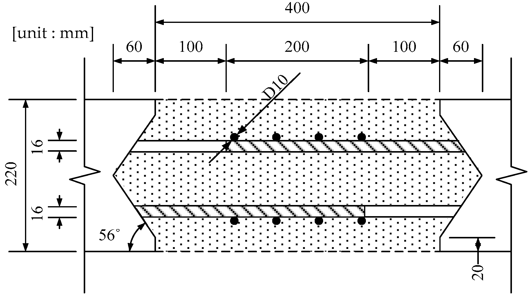
In the modular specimen, two modules of a 1000 mm width, a 220 mm height, and a 1400 mm length were prepared using concrete with a specified concrete strength of 50 MPa and D16 steel reinforcements with a strength of 400 MPa, according to load and resistance factor design (LRFD)’s “Bridge Design Specifications” (AASHTO), “Bridge Design Code” (MLTMA), and “Korea Structural Concrete Design Code” (KCI) [15,16,17,18]. Each module was connected with a lapped splice of steel reinforcements and ultra-high-strength concrete (UHSC) with a specified concrete strength of 120 MPa. The steel reinforcements of the joint were the same as those used for the modules and were connected in a 200-mm-long lapped splice. The total length was 3400 mm.
2.2. Loading Test Setup
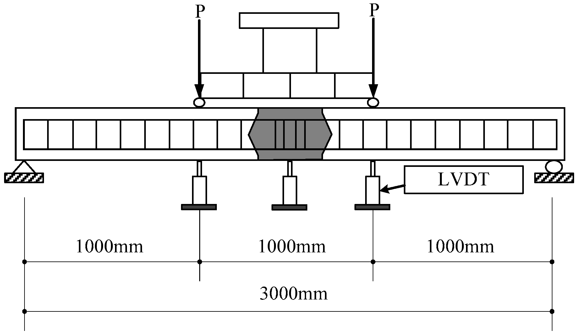
A 500 kN actuator was used, and the 4-point loading method shown in Figure 3 was adopted to allow the maximum moment to occur in the joint of the experimental specimen. As shown in Figure 3, the clear span of the specimen was 3000 mm. Loads were applied at the L/3 and 2L/3 locations, and linear variable differential transformers (LVDTs) were installed at three locations, namely the center span and the two loading points. The designed working load was 30.5 kN according to the Bridge Design Code 2010 [17]; however, a 79.1 kN load, which is 60% of the static maximum load of 131.9 kN, was applied because the practical load is generally higher than the working and crack loads. After 1, 102, 103, 104, 5 × 10⁴, 105, and 2 × 10⁵ load cycles, a static load was applied to measure the deflection. The initial deflection data from the cyclic loading test were used in this study to review the serviceability of the instantaneous deflection.
2.3. Loading Test Result
Figure 4 shows the cracks before failure after 200,000 load cycles. For all the specimens in failure, the cracks exhibited a similar shape, but in a different sequence of progression for each integral and modular specimen. For the integral specimen shown in Figure 4a, the cracks first appeared at the bottom-center of the specimen. Further cracking developed towards the sides, away from the center, as the load was increased, exhibiting cracking typical of reinforced concrete beams. However, for the modular specimen, the initial cracks started with the separation of the precast concrete module from the connecting high-strength concrete with the separation distance increasing with increasing load. The cracks propagated from the loading points to the support points and rupture occurred at the cracks in the high-strength concrete section at the third point in Figure 4b.
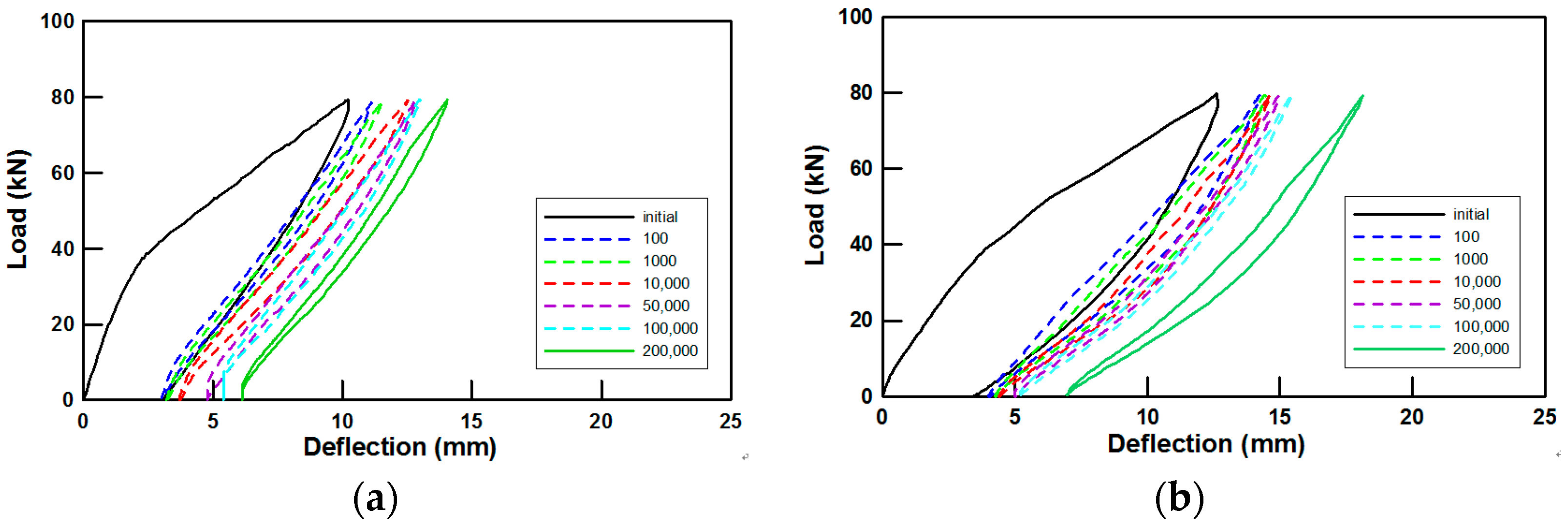
Cyclic loading was applied to analyze the joint behavior of the modular bridge. The test results are given in Table 1. As the cyclic loading progressed, the residual and maximum deflections increased. The overall deflection of the integral specimen increased steadily as the loading cycle progressed. However, the modular specimen exhibited a different deflection behavior, as shown in Figure 5. The deflection increased sharply for the first 100 load cycles, after which its rate of increase slowed. This continued up to the 100,000th cycle, after which the rate of increase began to rise dramatically until the 200,000th cycle and final static loading. This behavior was due to the crack propagation characteristics of the joint separation.
According to Equation (1), the theoretical deflection was calculated using the effective moment of inertia to compare the deflection of the modular specimen with the values given in the design code [18].
Here, is the effective moment of inertia, the moment of inertia of the gross concrete section, the moment of inertia of the cracked section, the cracking moment, and the applied moment.
Table 2 gives the moments of inertia of the gross and cracked concrete sections and the cracking moment [16].
The results are shown in Figure 6. The deflection given by the code underestimates the experimental results of the tested specimen. The specimen was more sensitive to the moment of inertia of the cracked section because it had a low thickness of 220 mm compared to general beams used by the design code for the effective moment of inertia when cracking occurred. However, the values at 79.1 kN for the integral specimen were relatively accurate as the crack progressed steadily. The difference increased with increasing load, reaching 2.41 mm at maximum load. The joint separation of the specimen during initial loading was thought to have dramatically reduced the moment of inertia, resulting in a significant difference from the effective moment of inertia suggested by the code. In addition, the design code does not take into account the modulus of elasticity of UHSC at the joints.
2.4. Estimation of Deflection
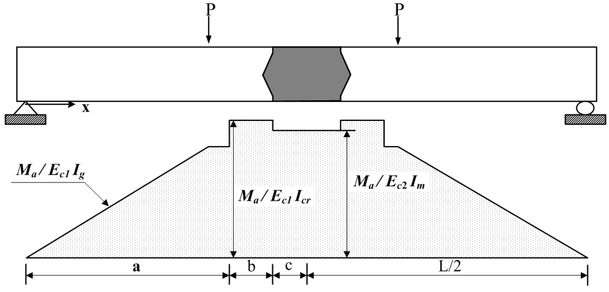
The difference between the strength of the precast concrete module and that of the concrete used for the joint was considered in order to precisely estimate the deflection of the modular specimen with joint. To reflect the effects of the initial cracks at the joint, the attached transmission length () was redefined as a new crack area in the specimen. This relationship of the attached transmission at the crack interface was used to induce tension-stiffening behavior of the reinforced concrete [19,20,21]. In this study, tension-stiffening was applied to the precast and joint interface because the interface was immediately separated by the initial loading; thus, the behavior of the modular specimen can only be explained by the attachment of the concrete and reinforcement. Figure 7 shows the change in the curvature diagram, which reflects the concrete strength and the new crack area. The concrete that was cast at the joint had a strength of 120 MPa, whereas that used for the module had a strength of 50 MPa. The modulus of elasticity at the high-strength joint increased, resulting in a reduction in curvature of the joint. The moment of inertia of the crack area with length , which reflects the effect of the initial cracks, was changed to the moment of inertia of the cracked section, thereby increasing the curvature.
The proposed curvature diagram can be divided into three parts, namely a, b, and c, as shown in Figure 7. The cross-section in part (a) is a gross section not affected by the crack. Part (b) reflects the effect of the initial cracks. Part (c) reflects the effect of the 120 MPa UHSC. The deflections of each section can be obtained by applying the moment area and unit load methods, as shown in Equations (2) and (3).
2.5. Test Cases
The deflections in the four cases were calculated by considering the effect of the joint separation during loading and the elastic modulus of the high-strength concrete in the joint. Table 3 shows the details of the four cases. The cross-sections of the joints of Cases 1 and 2 are defined as the cracked section () under the assumption that they were affected by the cracks caused by the separation of the high-strength concrete area of the joint. For Cases 3 and 4, the moment of inertia of the gross concrete section () was applied, considering the cyclic loading test results (i.e., cracking of the high-strength concrete and failure of the specimen occur simultaneously). In addition, Cases 2 and 4 considered the attached transmission length () on the left and right sides of the initial cracked section. A 200-mm-long lapped splice at the joint was applied as an attached transmission length. The moments of inertia used are given in Table 2. Moduli of elasticity of 50 and 120 MPa were used in Equation (4). Additional strengths (∆f) of 4 and 6 MPa were added when the designed compressive strengths were under 40 MPa and over 60 MPa, respectively. The values between these points were determined through linear interpolation via
Here, is the compressive strength of concrete, and the additional strength of concrete.
3. Results and Discussion
Figure 8 shows the curvature diagram according to the load for each case. Based on these diagrams, the deflections under the following applied moments were calculated using Equation (1): , which is the moment immediately prior to the application of the cracked moment; , which is the moment immediately following the application of the cracked moment; ; ; and .
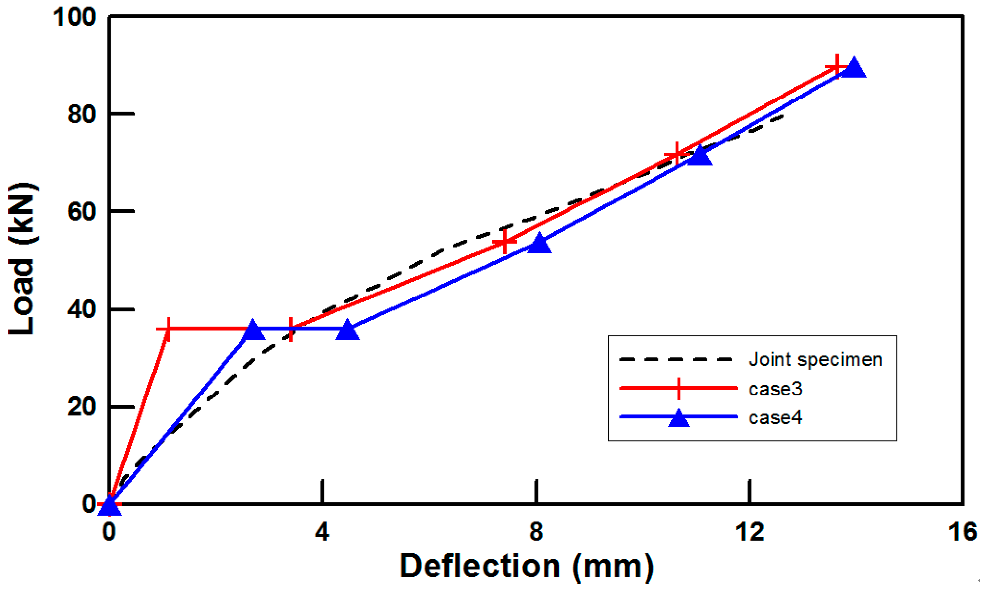
Table 4 gives the results and Figure 9 and Figure 10 display the load–deflection curves. All calculated cases exhibited an increase in the difference in deflection as the load increased. However, after , the difference decreased as the slope of the deflection of the modular specimen decreased. For Case 1, the deflection was accurately predicted to be a ratio of 0.74 compared to the experimental result before the application of the cracking moment. The deflection was overestimated after the application of the cracking moment as it dramatically increased to a ratio of 1.38. For Case 2, which reflects the attached transmission length, the deflection was overestimated for all loads with a ratio ranging from 1.21 to 1.7. For Case 3, the deflection ratio before the application of the cracking load was 0.32, which is the most underestimated ratio of all cases. However, after the cracking moment was applied, the deflection was most accurately predicted for ratios ranging from 0.96 to 1.17. Case 4 somewhat accurately predicted the deflections for both before and after the application of the cracking load. The former had a value of 0.78, whereas the latter ranged from 1.02 to 1.28. The error rates were calculated to be 36.5%, 46.6%, 22.8%, and 19.5% for the four cases, respectively.
Reflecting the attached transmission length to the left and right sides of the initial cracked surface below the cracking moment and considering that cracking occurs on the UHSC when the failure load is reached were effective to calculate the deflection of the precast modular slab with a joint. Because the steel reinforcements connected in the lapped splice shared the tensile forces on the left and right sides of the cracked surface, tensile stress in UHSC minimized when the separation of the joint occurred and UHSC is assumed non-cracking section until fail the specimen .
4. Conclusions
In this study, the deflection of precast modular slabs with joints was investigated. To consider the unique behavior of the joint, the deflection was estimated considering the change in the moment of inertia, elastic modulus of the concrete of the segmented specimens, and the attached transmission lengths. The curvature and unit load methods were used to calculate the deflection. The following observations and conclusions are made:
- To estimate the deflection of the modular specimen, the equation given by Branson was used. It was found that the deflection underestimated the experimental results by a difference of 2.41 mm.
- Detailed deflection estimations were performed for four cases that took into account the effects of the initial cracks at the joint and the modulus of elasticity. In addition, the attached transmission length () of the steel reinforcement and concrete on the crack surface at the joint was considered as a new crack area. The deflection values of Cases 1, 3, and 4 were underestimated as ratios of 0.74, 0.32, and 0.78, respectively. However, the value for Case 2 was overestimated to be 1.21 before the application of the cracking moment. Following the application of the cracking moment, the values for all cases were overestimated as average ratios of 1.4, 1.55, 1.04, and 1.19, respectively.
- Case 4 had an error rate of 19.5%, which was the most accurate prediction. This case demonstrates the effectiveness of estimating modular slabs with joints to reflect the attached transmission length (length of lapped splices) to the left and right sides of the joint and considering non-cracking section for UHSC of joint until fail the specimen.
- This study considered the difference in strength between precast concrete modules, the UHSC of the joint, and the attached transmission length to induce tension-stiffening for a new crack area. There are similar methods for evaluating deflection, such as weighted EI; however, engineers change the detailed calculation process based on their experiences such that consistent predictions are difficult to make. Therefore, dividing a section of precast concrete beam with joints can be an effective and structured prediction method.
Acknowledgments
This research was supported by the Basic Science Research Program through the National Research Foundation of Korea (NRF), which is funded by the Ministry of Education (NRF-2016R1A6A3A11931804), and by a National Research Foundation of Korea (NRF) grant also funded by the Korea government (MSIP) (No. NRF-2017R1A2B2012535).
Author Contributions
Jongho Park and Sun-Kyu Park conceived and designed the study. Jinwoong Choi and Yongjoon Jang wrote the manuscript. Sungnam Hong reviewed and edited the manuscript.
Conflicts of Interest
The authors declare no conflict of interest.
References
- Culmo, M.P. Accelerated Bridge Construction-Experience in Design, Fabrication and Erection of Prefabricated Bridge Elements and Systems; FHWA-HIF-12-013; Federal Highway Administration: Salem, OR, USA, 2011; pp. 52–270.
- Choi, J.; Park, S.K.; Kim, H.Y.; Hong, S. Behavior of high-performance mortar and concrete connections in precast concrete elements: Experimental investigation under static and cyclic loadings. Eng. Struct. 2015, 100, 633–644. [Google Scholar] [CrossRef]
- Li, L.; Jiang, Z. Flexural Behavior and Strut-and-tie Model of Joints with headed bar details Connecting Precast Members. Perspect. Sci. 2016, 7, 253–260. [Google Scholar] [CrossRef]
- Ryu, H.K.; Kim, Y.J.; Chang, S.P. Experimental study on static and fatigue strength of loop joints. Eng. Struct. 2007, 29, 145–162. [Google Scholar] [CrossRef]
- Buyukozturk, O.; Bakhoum, M.M.; Beattie, S.M. Shear Behavior of Joints in Precast Concrete Segmental Bridges. J. Struct. Eng. 1990, 116, 3380–3401. [Google Scholar] [CrossRef]
- Saibabu, S.; Srinivas, V.; Sasmal, S.; Lakshmanan, N.; Iyer, N.R. Performance evaluation of dry and epoxy jointed segmental prestressed box girders under monotonic and cyclic loading. Constr. Build Mater. 2013, 38, 931–940. [Google Scholar] [CrossRef]
- Issa, M.A.; Abdalla, H.A. Structural Behavior of Single Key Joints in Precast Concrete Segmental Bridges. J. Bridge Eng. 2007, 12, 315–324. [Google Scholar] [CrossRef]
- Graybeal, B.A. Behavior of Ultra-High Performance Concrete Connections between Precast Bridge Deck Elements. In Proceedings of the 2010 Concrete Bridge Conference: Achieving Safe, Smart & Sustainable Bridges, Phoenix, AZ, USA, 24 February 2010. [Google Scholar]
- Li, L.; Ma, Z.; Griffey, M.E.; Oesterle, R.G. Improved Longitudinal Joint Details in Decked Bulb Tees for Accelerated Bridge Construction: Concept Development. J. Bridge Eng. 2010, 15, 327–336. [Google Scholar] [CrossRef]
- Chapman, C.E. Behavior of Precast Bridge Deck Joints with Small Bend Diameter U-Bars. Master’s Thesis, University of Tennessee, Knoxville, TN, USA, 2010. [Google Scholar]
- Shah, B.N.; Sennah, K.; Kianoush, M.R.; Tu, S.; Lam, C. Experimental Study on Prefabricated Concrete Bridge Girder-to-Girder Intermittent Bolted Connections System. J. Bridge Eng. 2007, 12, 570–584. [Google Scholar] [CrossRef]
- Zhu, P.; Ma, Z.Z.; Cao, Q.; French, C.C. Fatigue Evaluation of Transverse U-Bar Joint Details for Accelerated Bridge Construction. J. Bridge Eng. 2012, 17, 191–200. [Google Scholar] [CrossRef]
- Grace, N.; Ushijima, K.; Baah, P.; Bebawy, M. Flexural Behavior of a Carbon Fiber-Reinforced Polymer Prestressed Decked Bulb T-Beam Bridge System. J. Compos. Constr. 2013, 17, 497–506. [Google Scholar] [CrossRef]
- Park, J.; Choi, J.; Lee, H.M.; Park, S.K.; Hong, S. Evaluation of Structural Behavior and Moment of Inertia on Modular Slabs Subjected to Cyclic Loading. J. Korea Inst. Struct. Maint. Insp. 2015, 19, 95–102. [Google Scholar] [CrossRef]
- Pohang Iron and Steel Company. Research & Business Development of Modular Bridges, Final ed.; Korea Agency for Infrastructure Technology Advancement: Anyang, Korea, 2015; pp. 1–160. [Google Scholar]
- American Association of State Highway and Transportation Officials. AASHTO LRFD Bridge Design Specification, 5th ed.; American Association of State Highway and Transportation Officials: Washington, DC, USA, 2010. [Google Scholar]
- Ministry of Land, Transport and Maritime Affairs. Bridge Design Code 2010, 1st ed.; Korea Road Association: Seoul, Korea, 2010.
- Korea Concrete Institute. Concrete Structures Design Code, 1st ed.; Korea Concrete Institute: Seoul, Korea, 2012. [Google Scholar]
- Gilbert, R.I.; Warner, R.F. Tension Stiffening in Reinforced Concrete Slabs. J. Struct. Div. 1978, 104, 1885–1900. [Google Scholar] [CrossRef]
- Floegl, H.; Mang, H.A. Tension stiffening Concept based on Bond Slip. J. Struct. Div. 1982, 108, 2681–2701. [Google Scholar]
- Visintin, P.; Sturm, A.B.; Oehlers, D.J. Long- and Short-term Serviceability Behavior of Reinforced Concrete Beams: Mechanics models for deflections and crack width. Struct. Concr. 2017, 18, 1–19. [Google Scholar] [CrossRef]
Figure 1.
Specifications of the specimen: (a) precast module before casting ultra-high-strength concrete (UHSC); (b) cross section of A-A; (c) modular specimen after casting UHSC.
Figure 1.
Specifications of the specimen: (a) precast module before casting ultra-high-strength concrete (UHSC); (b) cross section of A-A; (c) modular specimen after casting UHSC.
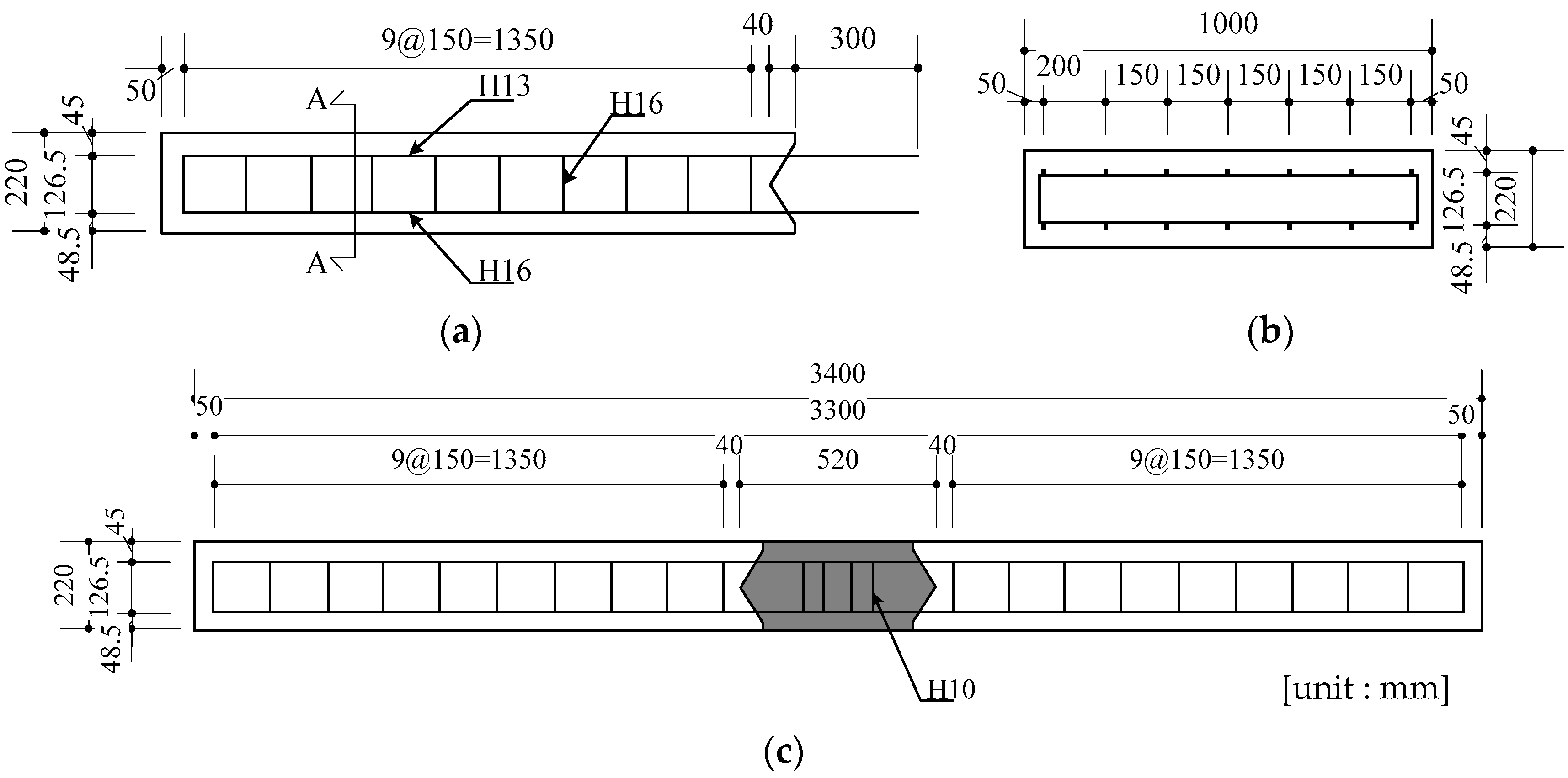
Figure 2.
Specifications of the joint.

Figure 3.
Experimental setup. LVDT: linear variable differential transformer.

Figure 4.
Result of crack progression: (a) cracking in the integral specimen; (b) cracking in the modular specimen.
Figure 4.
Result of crack progression: (a) cracking in the integral specimen; (b) cracking in the modular specimen.

Figure 5.
Load and deflection curves: (a) integral specimen; (b) modular specimen.

Figure 6.
Load and deflection curves of initial loading. KCI: Korea Structural Concrete Design Code.
Figure 6.
Load and deflection curves of initial loading. KCI: Korea Structural Concrete Design Code.
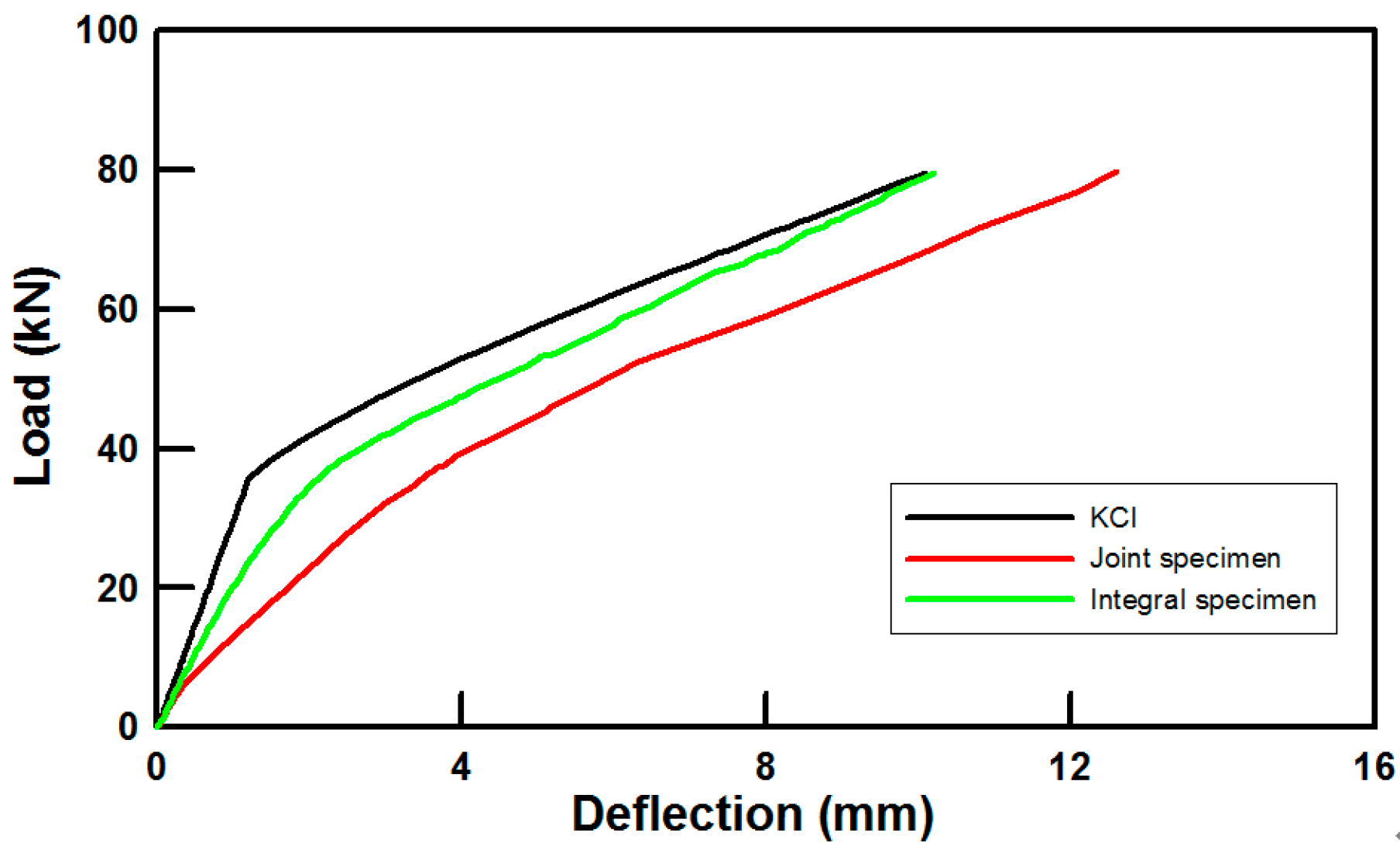
Figure 7.
Proposed curvature diagram of the modular specimen.

Figure 8.
Proposed curvature diagrams for the modular specimen: (a) Case 1; (b) Case 2; (c) Case 3; (d) Case 4.
Figure 8.
Proposed curvature diagrams for the modular specimen: (a) Case 1; (b) Case 2; (c) Case 3; (d) Case 4.
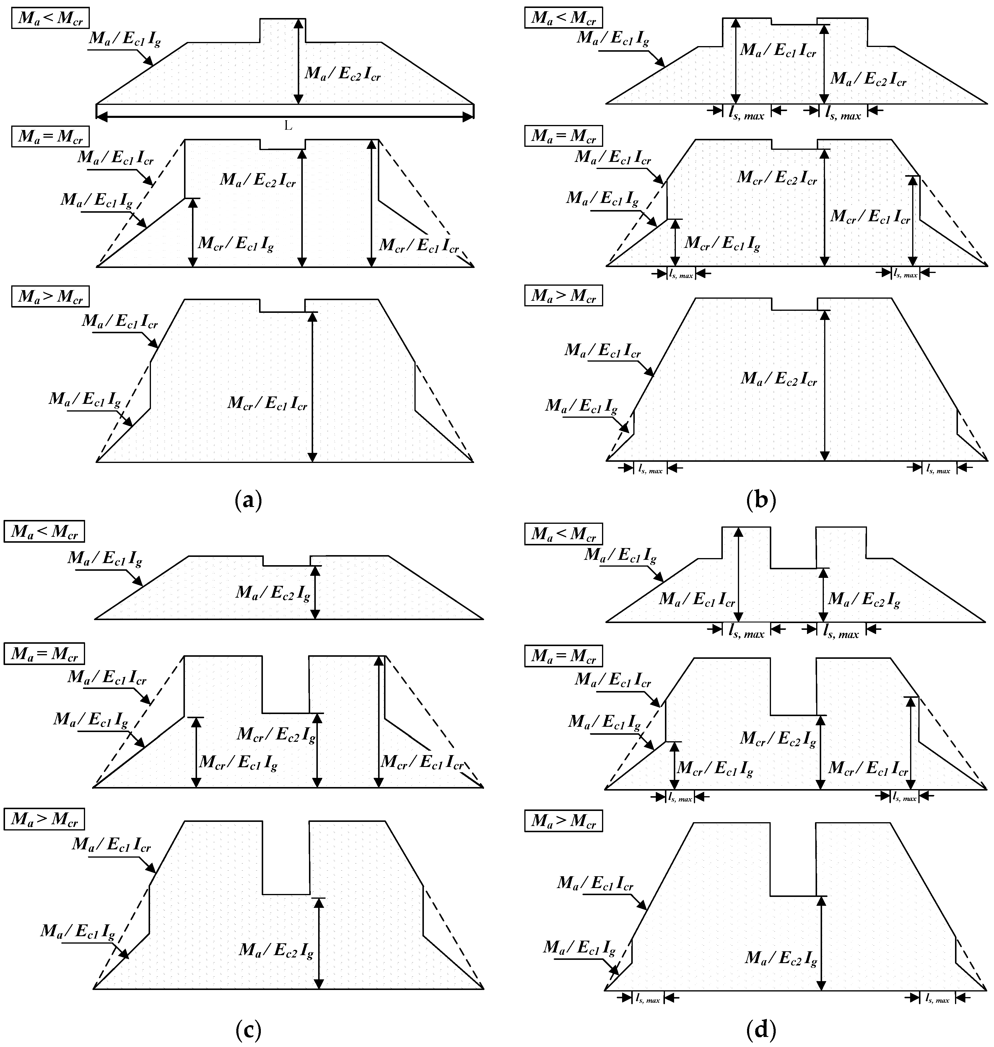
Figure 9.
Load and deflection curves of Cases 1 and 2.
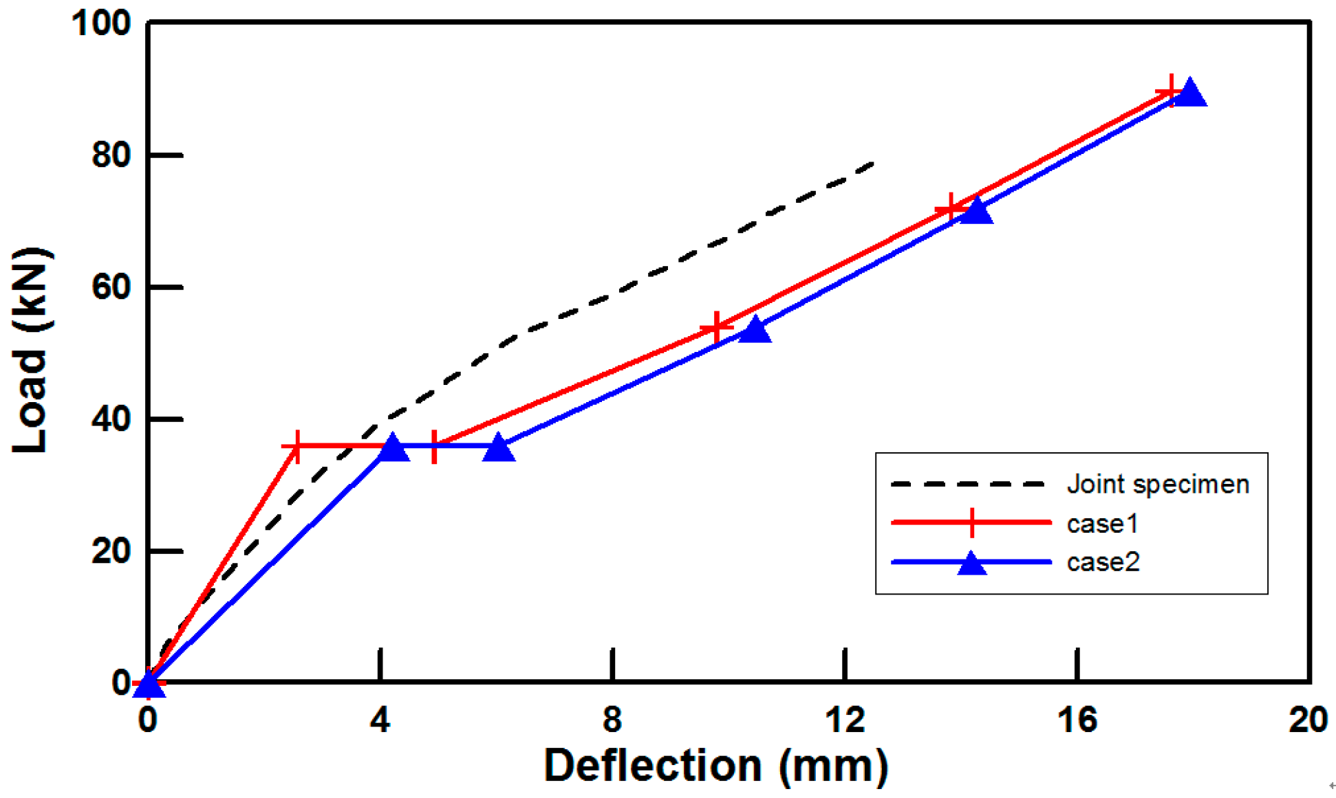
Figure 10.
Load and deflection curves of Cases 3 and 4.

Table 1.
Results of the cyclic loading test.
| Cycle Number | Deflection at Center (mm) | |
|---|---|---|
| Integral | Modular | |
| Initial | 10.21 | 12.62 |
| 100 | 11.14 | 14.25 |
| 1000 | 11.59 | 14.43 |
| 10,000 | 13.00 | 14.62 |
| 50,000 | 13.96 | 14.96 |
| 100,000 | 15.45 | 15.47 |
| 200,000 | 16.19 | 18.12 |
Table 2.
Values of effective moments of inertia.
| Coefficient | |||
|---|---|---|---|
| Value | 887.33 | 141.29 | 35.9 |
Table 3.
Analysis conditions.
| Specimen | Attached Transmission Length () | Moment of Inertia at Connection |
|---|---|---|
| Case 1 | - | cracked section |
| Case 2 | 200 mm | |
| Case 3 | - | gross concrete section |
| Case 4 | 200 mm |
Table 4.
Deflection results.
| Load | Modular | Case 1 | Case 2 | Case 3 | Case 4 | ||||
|---|---|---|---|---|---|---|---|---|---|
| mm | Ratio | mm | Ratio | mm | Ratio | mm | Ratio | ||
| 3.47 | 2.57 | 0.74 | 4.21 | 1.21 | 1.12 | 0.32 | 2.7 | 0.78 | |
| 3.56 | 4.92 | 1.38 | 6.04 | 1.7 | 3.40 | 0.96 | 4.47 | 1.26 | |
| 6.32 | 9.79 | 1.55 | 10.45 | 1.65 | 7.41 | 1.17 | 8.06 | 1.28 | |
| 10.86 | 13.83 | 1.27 | 14.27 | 1.31 | 10.64 | 0.98 | 11.07 | 1.02 | |
| - | 17.63 | - | 17.95 | - | 13.64 | - | 13.95 | - | |
| Avg. error | - | 0.365 | 0.4675 | 0.2275 | 0.195 | ||||
© 2017 by the authors. Licensee MDPI, Basel, Switzerland. This article is an open access article distributed under the terms and conditions of the Creative Commons Attribution (CC BY) license (http://creativecommons.org/licenses/by/4.0/).
Share and Cite
MDPI and ACS Style
Park, J.; Choi, J.; Jang, Y.; Park, S.-K.; Hong, S. An Experimental and Analytical Study on the Deflection Behavior of Precast Concrete Beams with Joints. Appl. Sci. 2017, 7, 1198. https://doi.org/10.3390/app7111198
AMA Style
Park J, Choi J, Jang Y, Park S-K, Hong S. An Experimental and Analytical Study on the Deflection Behavior of Precast Concrete Beams with Joints. Applied Sciences. 2017; 7(11):1198. https://doi.org/10.3390/app7111198
Chicago/Turabian StylePark, Jongho, Jinwoong Choi, Yongjoon Jang, Sun-Kyu Park, and Sungnam Hong. 2017. "An Experimental and Analytical Study on the Deflection Behavior of Precast Concrete Beams with Joints" Applied Sciences 7, no. 11: 1198. https://doi.org/10.3390/app7111198
Note that from the first issue of 2016, this journal uses article numbers instead of page numbers. See further details here.