Simultaneous Dual-Arm Motion Planning for Minimizing Operation Time


1
School of Science for Open and Environmental Systems, Graduate School of Science and Technology, Keio University, 3-14-1 Hiyoshi, Kohoku-ku, Yokohama 223-8522, Japan
2
Graduate School of Science and Technology, Keio University, 3-14-1 Hiyoshi, Kohoku-ku, Yokohama 223-8522, Japan
3
Department of System Design Engineering, Faculty of Science and Technology, Keio University, 3-14-1 Hiyoshi, Kohoku-ku, Yokohama 223-8522, Japan
*
Author to whom correspondence should be addressed.
Appl. Sci. 2017, 7(12), 1210; https://doi.org/10.3390/app7121210
Submission received: 23 October 2017
/
Revised: 22 November 2017
/
Accepted: 22 November 2017
/
Published: 23 November 2017
(This article belongs to the Section Mechanical Engineering)
Abstract
:Dual-arm robots are expected to perform work in a dynamic environment. One of the most basic tasks that a dual-arm robot does is pick-and-place work. However, this work is more complicated when there are several objects in the robot’s workspace. Additionally, it is likely to take a long time to finish the work as the number of objects increases. Therefore, we propose a method using a combination of two approaches to achieve efficient pick-and-place performance by a dual-arm robot to minimize its operation time. First, we use mixed integer linear programming (MILP) for the pick-and-place work to determine which arm should move an object and in which order these objects should be moved while considering the dual-arm robot’s operation range. Second, we plan the path using the rapidly exploring random tree so that the arms do not collide, enabling the robot to perform efficient pick-and-place work based on the MILP planning solution. The effectiveness of the proposed method is confirmed by simulations and experiments using an actual dual-arm robot.

1. Introduction
Dual-arm robots have attracted much attention in recent years [1]. One of the most basic tasks that an industrial dual-arm robot does is pick-and-place work. Pick-and-place work consists of tasks in which the robot carries objects from a start position (initial position) to a goal position. The dual-arm robot is expected to do this work in a dynamic environment, such as a house or a shop. It is necessary to do the pick-and-place work efficiently in a dynamic environment. The following three important points should also be considered when the dual-arm robot does this work: (1) collision avoidance of the arms; (2) which arm should move an object; and (3) the order in which the objects should be picked up and placed. There are several objects in an environment. Therefore, the last two points should particularly be considered because of their substantial impact on the time taken to finish the work.
In related studies, Doger et al. and Berensson et al. proposed a motion planning method to enable single arm type robot to grasp a target object in an environment in which there are multiple objects [2,3]. In addition, Srivastava et al. proposed a similar motion planning method for grasping a target object for a dual-arm robot. Specifically, they successfully moved two robot arms simultaneously and efficiently grasped a target object from among multiple objects [4]. Although Rodriguez et al. did not use dual-arm robots, they proposed a motion planning method for efficiently grasping a target object from multiple objects using multiple manipulators [5]. Moreover, Saut et al., using a dual-arm robot, proposed a method of transporting an object from one end of the workspace to the other by the handover of an object [6]. In an environment where there are multiple objects, they performed motion and path planning so that neither arm collides with any objects during handover. Both of the above studies proposed a motion or path planning method that can work efficiently in environments where there are multiple objects. However, the operation time of a robot was not taken into account explicitly. Huang et al. proposed a motion planning method that considers operation time. This method enables a single-arm robot to minimize the time taken to finish the work when a multiple determined-point manipulator is moved [7]. Rafi et al. proposed an approach to formulating the cost function for a motion planner intended for efficient human–robot collaboration on manipulation tasks in a shared workspace [8]. Similarly, Garrett et al. and Gaschler et al. efficiently performed a collection of tasks involving the manipulation of many objects [9,10]. In recent works, Bourbonnais et al. proposed trajectory planning optimization and real-time control of a special five-bar parallel robot. Although they achieved planning the optimal path for minimizing time, they did not focus on pick-and-place for multiple objects and for multiple manipulators [11]. Huang et al. proposed combination of part-dispatching rules to coordinate multi-robot system in the environments there are multiple object. Although they considered the order in which the objects should be picked-and-placed, they did not study the factors for efficiency such as minimizing time [12]. In addition, the studies mentioned above did not consider the elements of dual-arm robots. Applying these methods for a dual-arm robot is difficult considering the three abovementioned points. As far as the authors know, no study has ever considered the operation time a dual-arm robot takes to finish its work when multiple manipulators move simultaneously. Therefore, we propose a motion planning method to minimize the operation time taken to finish work considering the three points mentioned above and focusing on the pick-and-place work of a dual-arm robot.
Considering the three points described earlier, it takes a long time to search for the optimal combination without collision if we use a typical path-planning algorithm that uses the rapidly exploring random tree (RRT) [13] or probabilistic roadmaps (PRM) [14]. It is similar using expanded type RRT [15] or PRM [16]. This is because we can only decide which arms can move an object and in which order the objects can be picked and placed. There are also combinations when objects exist in the workspace. This is not a realistic approach in terms of computation time when a large number of objects exist. Accordingly, we employ mixed integer linear programming (MILP) for the pick-and-place work to determine which arms should move an object and in which order these objects should be moved. We plan a path to avoid collisions using the RRT, enabling the robot to perform an efficient pick-and-place task based on the task planning solution from the MILP. Finally, experiments using a real dual-arm robot were performed to verify the effectiveness of the proposed method.
2. Materials and Methods
2.1. Formulation of the Pick-and-Place Work
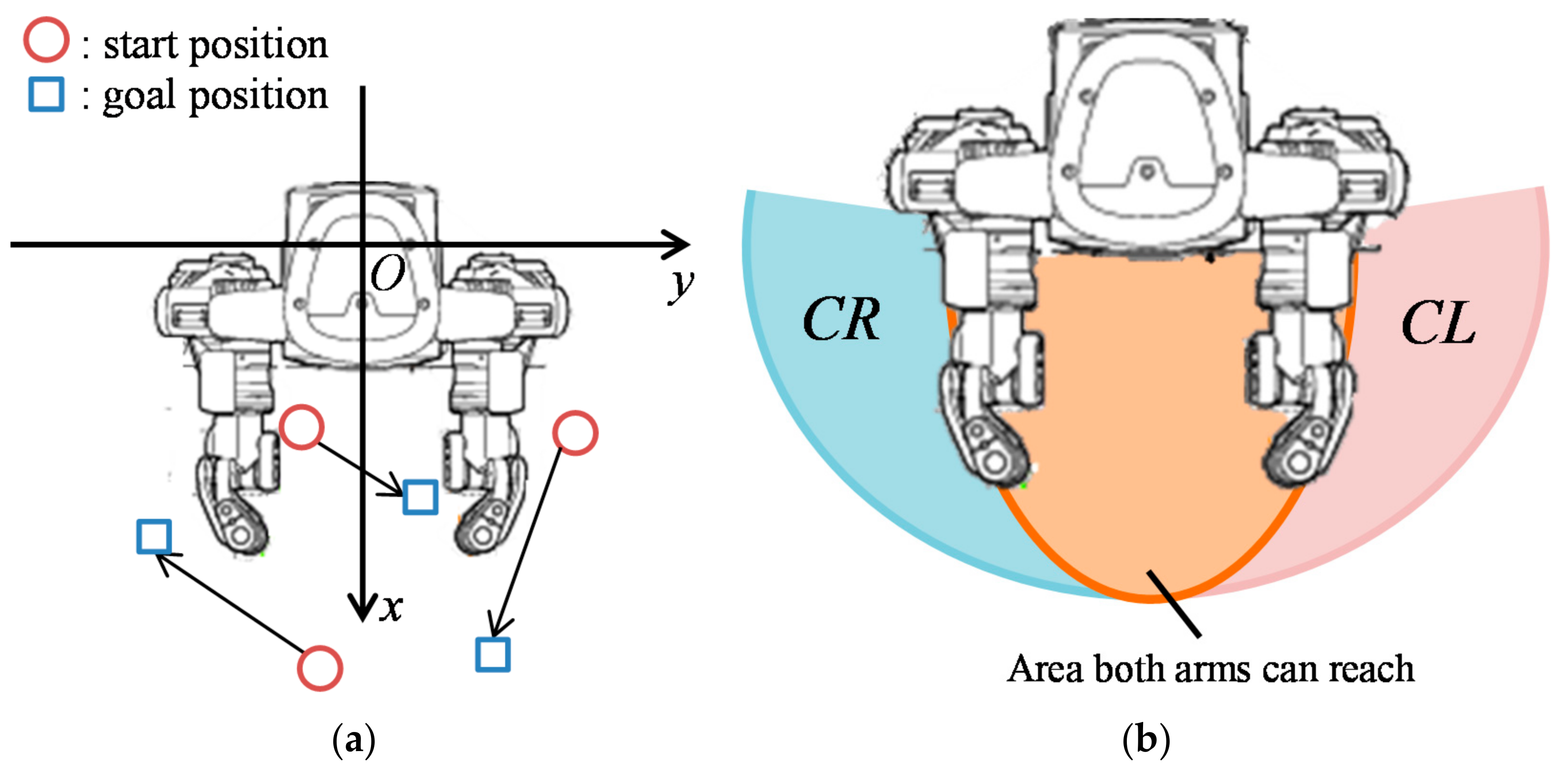
We formulated the pick-and-place work for a dual-arm robot that carries each object to the goal positions. Figure 1a shows a right-handed system of the dual-arm robot and an example of the problem when objects and goal positions exist. The circles in Figure 1a indicate the start position of each object. The squares represent each goal position. The object must be moved to each goal position from each start position by either of the arms. This problem converts into the problem of sharing multiple transport tasks, which is regarded as the task of moving an object to a goal position from a start position. This problem is also similar to the travelling salesman problem [17], which is generated when the distance or cost between each city, total distance, or total cost that incurs when a salesman moves is minimized. Constraints, such as the operating range of the dual-arm robot, mean that we can formulate the pick-and-place work of the dual-arm robot as an MILP.
Equation (1) is the objective function, where is a set of manipulator tasks, is the set of manipulators, is the left arm, is the right arm, is the cost from task to task for manipulator , and is the binary variable indicating whether the manipulator moved from task to task . The decision variable is if manipulator is assigned to move from task to task , and 0 otherwise. The minimax type of objective function to minimize the maximum path length of each manipulator is set. In other words, the time to finish the pick-and-place work is minimized because it depends on the arm, which has to move along a longer path if the manipulator moves at a constant velocity. We described linear constraints below.
Equation (2) forbids the manipulator from moving between the same task (from task to task ).
Equations (3) and (4) also forbid movement from Task 1 to Task 2 or from Task 2 to Task 1 because Task 1 indicates the left arm, and Task 2 indicates the right arm.
Equation (5) ensures that manipulator moves from the start position. Equation (6) ensures that manipulator finally moves back to the start position.
Equation (7) to Equation (10) forbid the paths that manipulator cannot select because Tasks 1 and 2 denote the left and right arms, respectively.
where is a set of tasks. Equations (11) and (12) mean that each task must be executed by either arm.
Equation (13) is a path continuity constraint, which means that manipulator must execute task and any other task after executing one task.
where is the number of tasks executed by the manipulator, while is the maximum number of tasks a manipulator may execute. Let be the minimum number of tasks a manipulator may execute. Equations (14) and (15) are the subtour elimination constraints of the formulation proposed by Kara and Bektas [18]. A subtour is a path that does not include Tasks 1 and 2. The constraints herein allow only two subtours because the dual-arm robot has two manipulators.
Equation (16) to Equation (19) are the operation range constraints of the dual-arm robot. is a set of tasks that should be executed by the left arm because the object or its goal position is in a location that can only be reached by the left arm. Equations (16) and (17) ensure that a task belonging to must be executed by the left arm. is a set of tasks that should be executed by the right arm. Equations (18) and (19) ensure that a task belonging to must be executed by the right arm. Figure 1b shows the operation range of HIRO, a real dual-arm robot produced by KAWADA Robotics Corporation, as well as the area definition of and . For example, if the object or its goal position is in the location , its task belongs to . Equation (20) defines the binary variable and the range of integers , and .
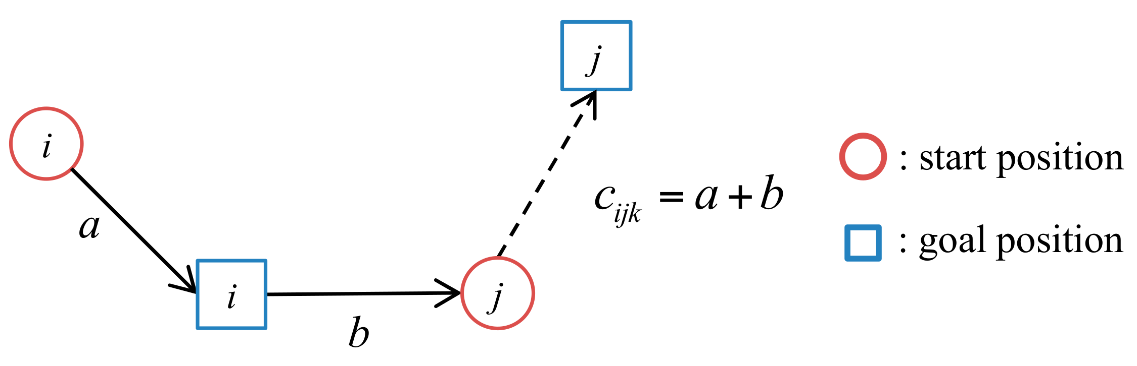
We define cost below. First, the Euclidean distance from the current position of the manipulator to a certain start position is and the Euclidean distance from the start point to the goal positions is . Cost is defined as (Figure 2). Specifically, this is equal to the Euclidean distance until the end of the work, which means manipulator moves from tasks to . Using this method, we can calculate cost of each task. In addition, the Euclidean distance between tasks does not depend on which arm moves. Hence, we define the relationship between and as .
2.2. Path Planning with RRT
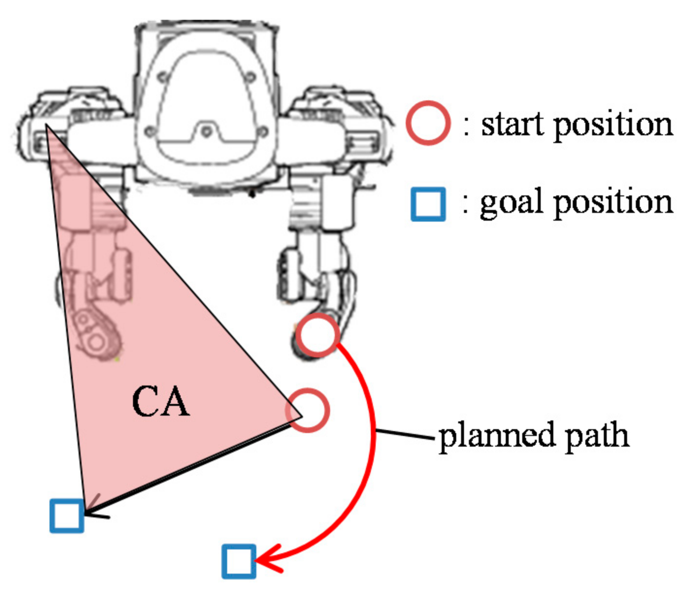
The solution is derived from the MILP. The path to avoid a collision is planned with the RRT using the solution from MILP based planning that decides which arm moves an object and in which order these objects are to be picked and placed. Assuming that the manipulator operates at a constant speed, we judged where the collision occurs from the solution. Path planning is performed by using RRT for the part where collision occurs, obtained from this judge. For example, the part for path planning is a part in which the manipulator linearly moves, such as when moving from the start position to the goal position. In a part where collision occurs, the arm has a longer path decided from the solution is defined as a dynamic obstacle to prevent the finish time from increasing. The arm has a longer path is decided by comparing total path length from the solution. Then, we plan the path of the other arm's end effector with RRT. An arm defined as a dynamic obstacle will linearly move to its destination. A collision-free path is planned to exist outside of areas that can possibly collide with each arm. Here, this area is defined as the collision area (CA) on the plane. The arm has a shorter path length that avoids the CA. The proposed method can then avoid a collision with each arm. Figure 3 shows one of example of the CA, which is defined as a triangle composed of three points, and the current points of the arm’s end effector, the arm destination, and first arm joint are regarded as a dynamic obstacle. Figure 3 shows that the right arm is defined as a dynamic obstacle.
3. Results and Discussion
3.1. Simulation
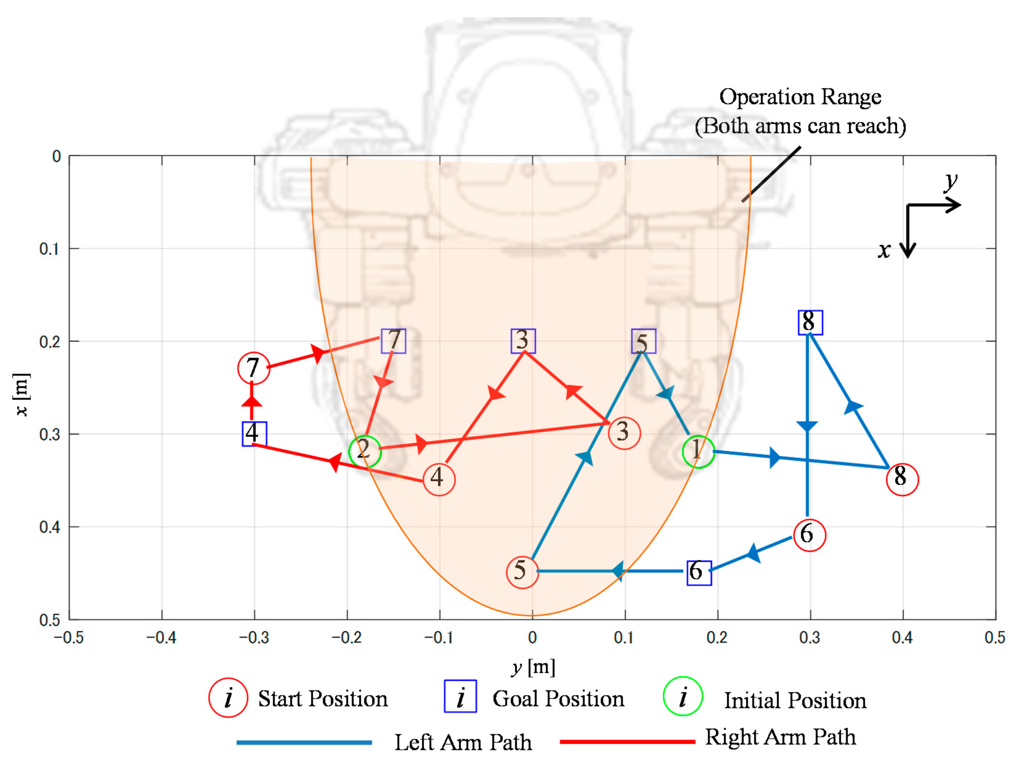
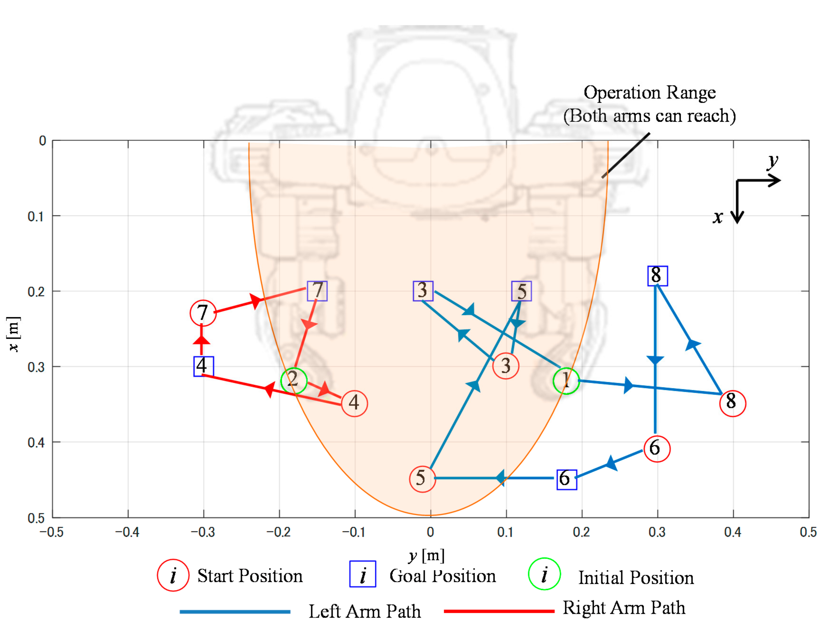
Six objects were used for the dual-arm robot’s workspace in the simulations. Table 1 shows each object’s initial and goal positions and object ID. The object ID means “task” referred in the method. The object’s initial and goal position layouts are provided in Figure 4 and Figure 5. As mentioned before, Object (Task) 1 and Object (Task) 2 indicate the left and right arms, respectively. Therefore, these tasks do not have a goal position. Moreover, simulations were performed with a comparative method, which does not consider the operation range, as the method proposed in this study does, but instead determines the object to move by its initial position. For example, the left arm must move an object and perform its task if the object’s initial position is . Similarly, the right arm must move the object and perform its task if the object’s initial position is . This means that the objects on the left side of the robot must be moved by the left arm, and vice versa. This method leads to the solution of the optimal path, where the cost is minimized in each arm. Figure 4 shows the solution obtained by the proposed method and Figure 5 illustrates the solution obtained by the comparative method.
The results shown in Figure 4 indicate that the proposed method can execute planning while considering HIRO’s operation range. Objects 6 and 8 were only moved by the left arm. Similarly, Objects 4 and 7 were only moved by the right arm. However, in the evaluation of the Euclidean distance, a comparison of the proposed and comparative methods in Table 2 shows that the proposed method minimized the maximum path length of each arm. The total path length of the sum of the left and right arms of the proposed method was shorter than that of the comparative method. However, the proposed method should take a shorter time to finish the work because the longer path obtained by the proposed method was 1.35 m. In contrast, the longer path obtained by the comparative method was 1.69 m.
As indicated, the time taken to finish work depended on the longer path. The proposed method can clearly and efficiently execute all tasks. The difference between the proposed and comparative methods is implied by Object 3. Altogether, Object 3 was moved to the goal position by the left arm using the comparative method, whereas it was moved to the goal position by the right arm using the proposed method. Figure 4 and Figure 5 show that Objects 3 and 5 can be moved by both arms. Nevertheless, the comparative method determined which arm can move an object simply using the coordinate. This move required more time to finish the work because the left arm must move four objects. In contrast, the number of objects moved by the right arm is three. Consequently, the proposed method can shorten the left arm’s path length. This result reveals that Equations (1)–(20) of the MILP formulation were effective for the pick-and-place work.
3.2. Experiment
Experiments using the HIRO dual-arm robot were performed to verify the effectiveness of the proposed method. Blocks made of sponge were used for the verification. Six blocks, colored red, green, yellow, grey, brown, and black, were used. Two experiments were performed. The first experiment confirmed that the dual-arm robot can utilize the proposed motion planning method that minimizes the time spent to finish the work (Experiment 1). The second experiment tested the collision avoidance for each arm and confirmed that the path planning with RRT is effective when there are possible collisions with each moving arm (Experiment 2).
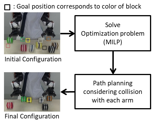
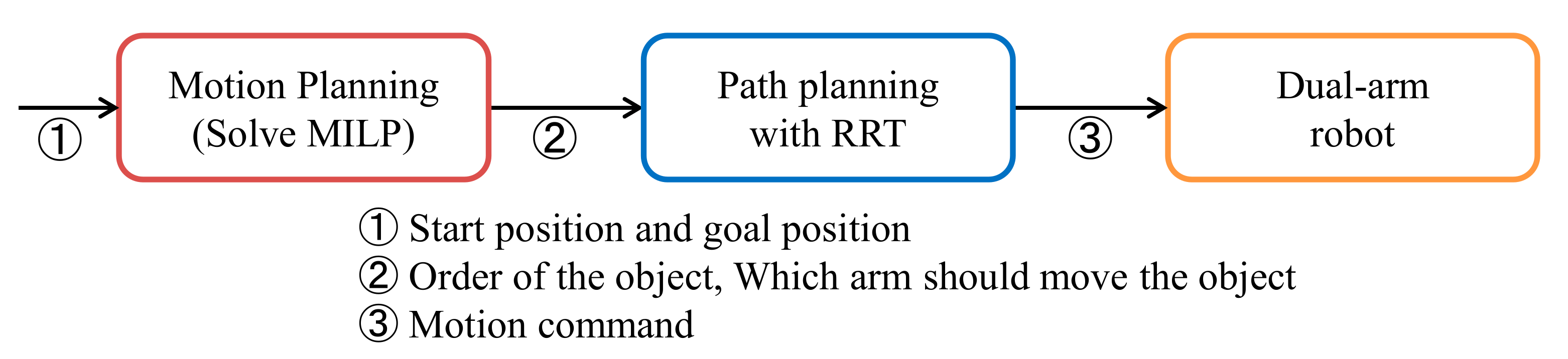
Figure 6 shows a system chart of the experiment. In both experiment, we assumed that start and the goal position can be acquired. The flow until the dual arm robot moves is explained below. First, MILP is solved with start position and goal positions as input. Based on the solution obtained by MILP, path is planned by RRT. As a result of the above, since the path on which the robot operates is determined, motion command is send to the dual arm robot.
3.2.1. Verification Experiment
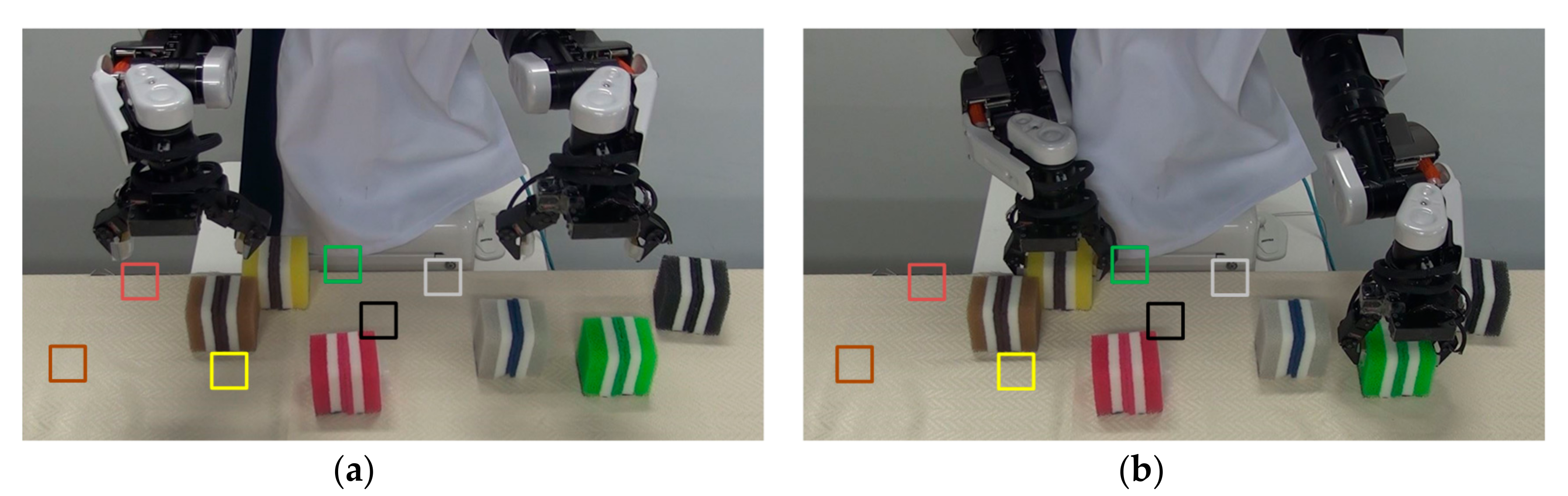
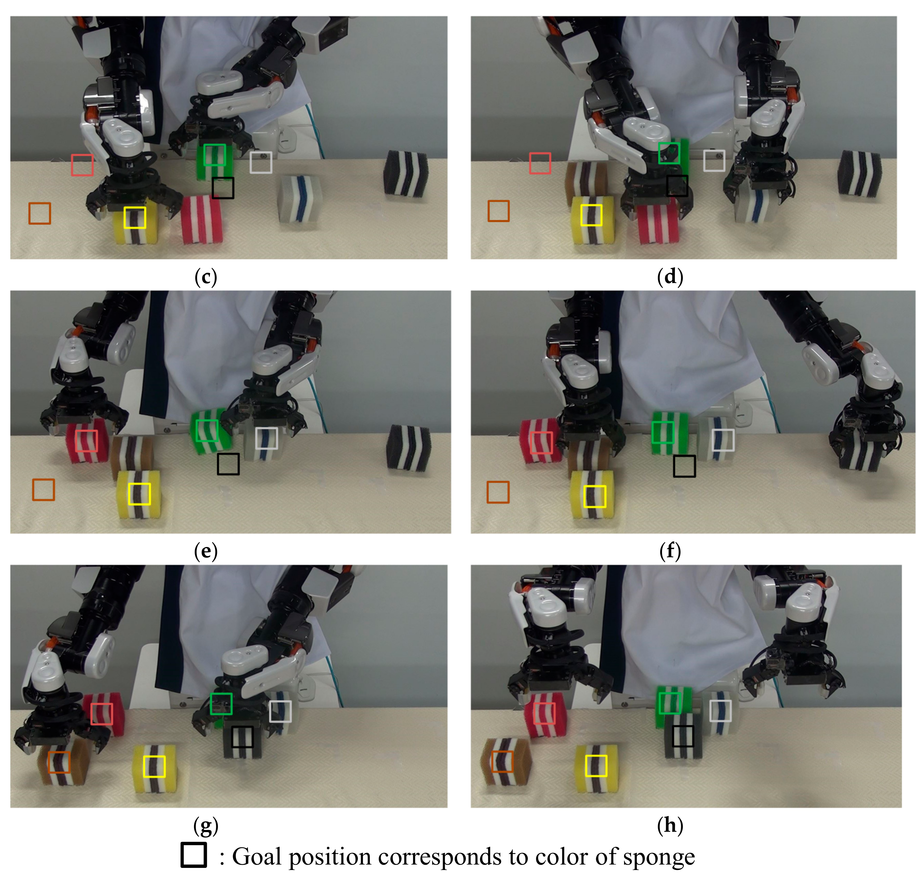
The motion of the dual-arm robot is shown in Figure 7 and Video S1. The squares in the images in Figure 7 show the goal position, which corresponds to the respective color of the sponges. The correspondence between the color and object ID is shown in Table 3. We confirmed that the dual-arm robot can perform the pick-and-place work without collision between the left and right arms. We also confirmed that the robot can execute the pick-and-place work according to the solutions obtained by the MILP, as shown in Table 4. The proposed motion planning and path planning algorithms were effective for the dual-arm robot in the verification experiment.
3.2.2. Collision Avoidance with Each Arm
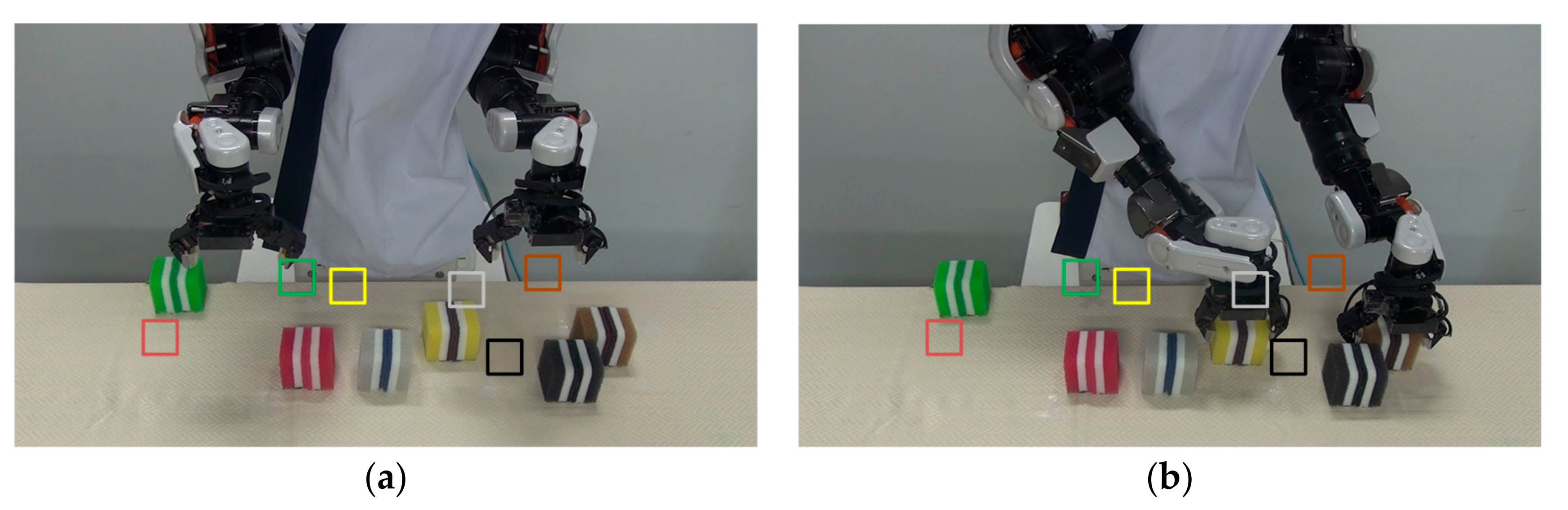
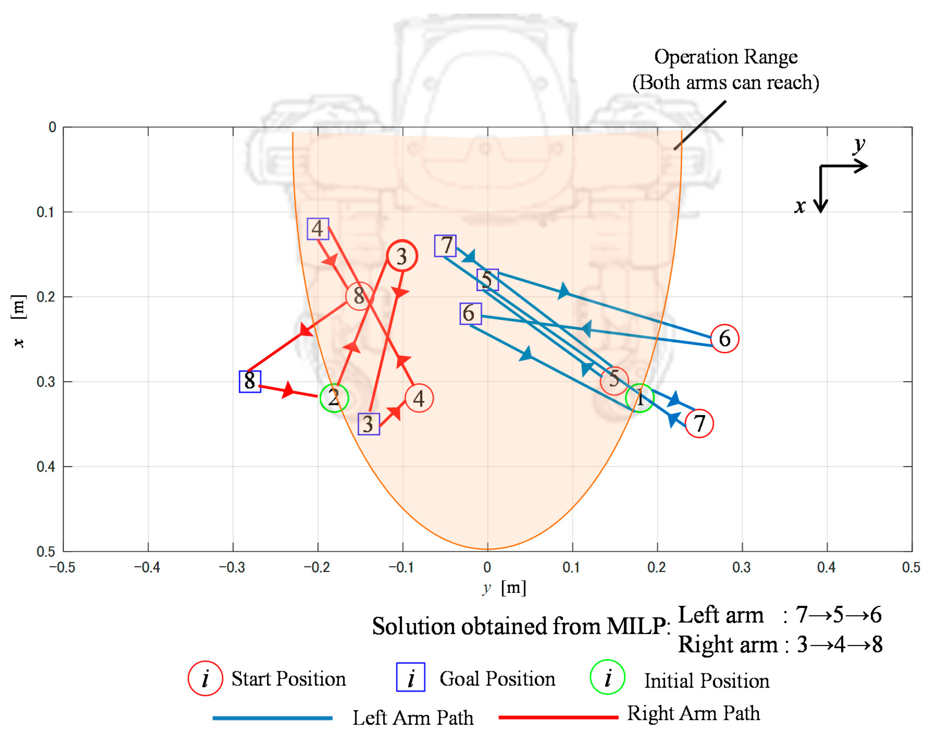
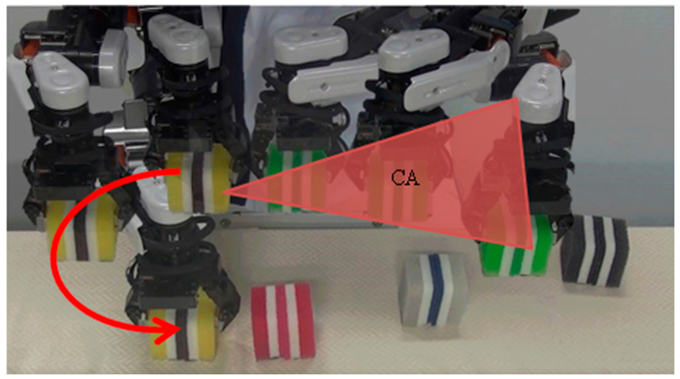
We conducted experiments with different object placement patterns. In these experiments, operation that includes the collision avoidance obtained by the RRT method described in Section 2.2 was demonstrated during the pick-and-place work. Table 5 shows the coordinates of the start and goal positions, and the MILP solution is shown in Figure 8. The motion of the dual-arm robot is shown in Figure 9 and Video S2. Here, the relationship between the object ID and sponge color is the same as in Table 4. In the Figure 9, the dual-arm carries the yellow block using the right arm and the green block using the left arm. In Figure 10, we confirm that the right arm passes the path indicated by the red arrow, avoids the CA, and carries the object. The results of this experiment confirm that the proposed method can perform pick-and-place work without collision with either arm.
3.3. Computation Time
Table 6 shows the computation time of proposed method with respect to the number of objects. Simulation was performed 100 times by giving start and goal positions at random. Specifically, the coordinates of the start and goal positions are randomly generated based on a uniform distribution within the workspace. From the result, average and standard deviation of computation time required to solve MILP were calculated. The computer applied in this simulation uses a 4.0 GHz Intel Core i7-4790K CPU, 16.0 GB of memory, and Windows 7 Professional.
In this section, we define the conventional method as the way costs are calculated from the path planned by RRT before solving MILP. It means path planning with RRT is performed with all combinations . The computation time of RRT was calculated using the result of 0.3 s/part measured in Experiment 2. In the conventional method, we referred that there are combinations. Therefore, we can calculate the computation time of RRT by multiplying 0.3 and . For example, when , the computation time is about s, and it increases depending on the number of objects. On the other hand, in the proposed method, since the number of times RRT is executed is at most, we can calculate the computation time of RRT by multiplying 0.3 and . For example, when , the computation time is about 2.10 s at most. Thus, we can estimate that total time for planning in the proposed method is about 3.21 s from average time in Table 6.
From the result, the proposed method can significantly reduce the computation time compared with the conventional method. In addition, the proposed method can complete the calculation within the real time, so it can be applied sufficiently even in a dynamic environment.
4. Conclusions
In this study, we focused on the pick-and-place work of a dual-arm robot and proposed a motion planning method that minimizes the time taken to finish the work. Compared to the conventional method, which determines which arm moves an object only using the object positions, the proposed method in the simulation results plans a path that considers the dual-arm robot’s operation range and minimizes the maximum path length of the arms. It was confirmed that the proposed method minimized the time taken to finish the pick-and-place work. It was also confirmed that the path planning using the RRT enabled the dual-arm robot to execute the pick-and-place work without collisions between the arms.
In the future, we need to examine in more detail the following two topics. The first is hand-over work. The dual-arm robot needs to be able to hand over an object from the left to right arm if the existing object can only be reached by the left arm and the goal position point can only be reached by the right arm (and vice versa). Second, we plan to extend the CA to three-dimensional space, that is, coordinates on the plane.
Supplementary Materials
The following are available online at https://www.mdpi.com/2076-3417/7/12/1210/s1, Video S1: Verification Experiment 1, Video S2: Verification Experiment 2.
Acknowledgments
This study was supported by “A Framework PRINTEPS to Develop Practical Artificial Intelligence” of the Core Research for Evolutional Science and Technology (CREST) of the Japan Science and Technology Agency (JST) under Grant Number JPMJCR14E3.
Author Contributions
Jun Kurosu, Ayanori Yorozu and Masaki Takahashi conceived and designed the proposed method and the verification experiments; Jun Kurosu performed the experiments; and Jun Kurosu wrote the paper.
Conflicts of Interest
The authors declare no conflict of interest.
References
- Smith, C.; Karayiannidis, Y.; Nalpantidis, L.; Gratal, X.; Dimarogonas, P.; Qi, D.V.; Kragic, D. Dual arm manipulation—A survey. Robot. Auton. Syst. 2012, 60, 1340–1353. [Google Scholar]
- Dogar, M.; Srinivasa, S. A framework for push-grasping in clutter. In Proceedings of the Robotics: Science and Systems, Los Angeles, CA, USA, 27–30 June 2011; pp. 65–72. [Google Scholar]
- Berenson, D.; Srinivasa, S.; Ferguson, D.; Collet, A.; Kuffner, J. Manipulation Planning with Workspace Goal Regions. In Proceedings of the IEEE International Conference on Robotics and Automation, Kobe, Japan, 12–17 May 2009; pp. 618–624. [Google Scholar]
- Srivastava, S.; Fang, E.; Riano, L. Combined Task and Motion Planning Through an Extensible Planner-Independent Interface Layer. In Proceedings of the IEEE International Conference on Robotics and Automation, Hong Kong, China, 31 May–7 June 2014; pp. 639–646. [Google Scholar]
- Rodriguez, C.; Montano, A.; Suarez, R. Planning manipulation movements of dual-arm system considering obstacle removing. Robot. Auton. Syst. 2014, 62, 1816–1826. [Google Scholar] [CrossRef] [Green Version]
- Saut, J.; Gharbi, M.; Corte, J.; Sidobre, D.; Simeon, T. Planning Pick and Place tasks with two-hand regrasping. In Proceedings of the IEEE/RSJ International Conference on Intelligent Robots and Systems, Taipei, Taiwan, 18–22 October 2010; pp. 4528–4533. [Google Scholar]
- Huang, Y.; Gueta, B.; Chiba, R.; Arai, T.; Ueyama, T.; Ota, J. Selection of manipulator system for multiple-goal task by evaluating task completion time and cost with computational time constraints. Adv. Robot. 2013, 27, 233–245. [Google Scholar] [CrossRef]
- Hayne, R.; Luo, R.; Berenson, D. Considering avoidance and consistency in motion planning for human-robot manipulation in a shared workspace. In Proceedings of the IEEE International Conference on Robotics and Automation, Stockholm, Sweden, 16–21 May 2016; pp. 3948–3954. [Google Scholar]
- Garrett, C.R.; Lozano-Perez, T.; Kaelbling, L.P. Ffrob: An efficient heuristic for task and motion planning. Algorithmic Found. Robot. 2015, 6, 179–195. [Google Scholar]
- Gaschler, A.; Kessler, I.; Petrick, R.P.; Knoll, A. Extending the knowledge of volumes approach to robot task planning with efficient geometric predicates. In Proceedings of the IEEE International Conference on Robotics and Automation, Seattle, WA, USA, 26–31 May 2015; pp. 3061–3066. [Google Scholar]
- Bourbonnais, F.; Bigras, P.; Bonev, I.A. Minimum-time trajectory planning and control of a pick-and-place five-bar parallel robot. IEEE/ASME Trans. Mechatron. 2015, 20, 740–749. [Google Scholar] [CrossRef]
- Huang, Y.; Chiba, R.; Arai, T.; Ueyama, T.; Ota, J. Robust multi-robot coordination in pick-and-place tasks based on part-dispatching rules. Robot. Auton. Syst. 2015, 64, 70–83. [Google Scholar] [CrossRef]
- La Valle, S.M. Rapidly-Exploring Random Trees: A New Tool for Path Planning; Technical Report No. 98-11; Computer Science Department, Iowa State University: Ames, IA, USA, 1998. [Google Scholar]
- Kavraki, L.E.; Svestka, P.; Latombe, J.-C.; Overmars, M.H. Probabilistic roadmaps for path planning in high-dimensional configuration space. IEEE Trans. Robot. Autom. 1996, 12, 566–580. [Google Scholar] [CrossRef]
- La Valle, S.M.; Kuffer, J. Randomized kinodynamic planning. Int. J. Robot. Res. 2011, 20, 378–400. [Google Scholar] [CrossRef]
- Baumann, M.; Leonard, S.; Croft, E.A.; Little, J.J. Path planning for improved visibility using a probabilistic road map. IEEE Trans. Robot. 2010, 26, 195–200. [Google Scholar] [CrossRef]
- Bektas, T. The multiple traveling salesman problem: An overview of formulations and solution procedures. Omega 2006, 34, 209–219. [Google Scholar] [CrossRef]
- Kara, I.; Bektas, T. Integer linear programming formulations of multiple salesman problem and its variations. Eur. J. Oper. Res. 2006, 174, 1449–1458. [Google Scholar] [CrossRef]
Figure 1.
The example of pick-and-place problem: (a) definition of the problem (the number of objects equals three); and (b) operation range of HIRO.
Figure 1.
The example of pick-and-place problem: (a) definition of the problem (the number of objects equals three); and (b) operation range of HIRO.

Figure 2.
Definition of the cost
between tasks
and task

Figure 3.
Definition of the CA (Collision Area).

Figure 4.
Solution obtained by the proposed method.

Figure 5.
Solution obtained by the comparative method.

Figure 6.
System chart in the experiment. MILP: mixed integer linear programming; RRT: rapidly exploring random tree.
Figure 6.
System chart in the experiment. MILP: mixed integer linear programming; RRT: rapidly exploring random tree.

Figure 7.
Verification Experiment 1: (a) initial configuration; (b) picking the yellow and brown blocks; (c) placing the yellow and brown blocks; (d) picking the red and black blocks; (e) placing the red and black blocks; (f) picking the green and grey blocks; (g) placing the green and grey blocks; and (h) final configuration.

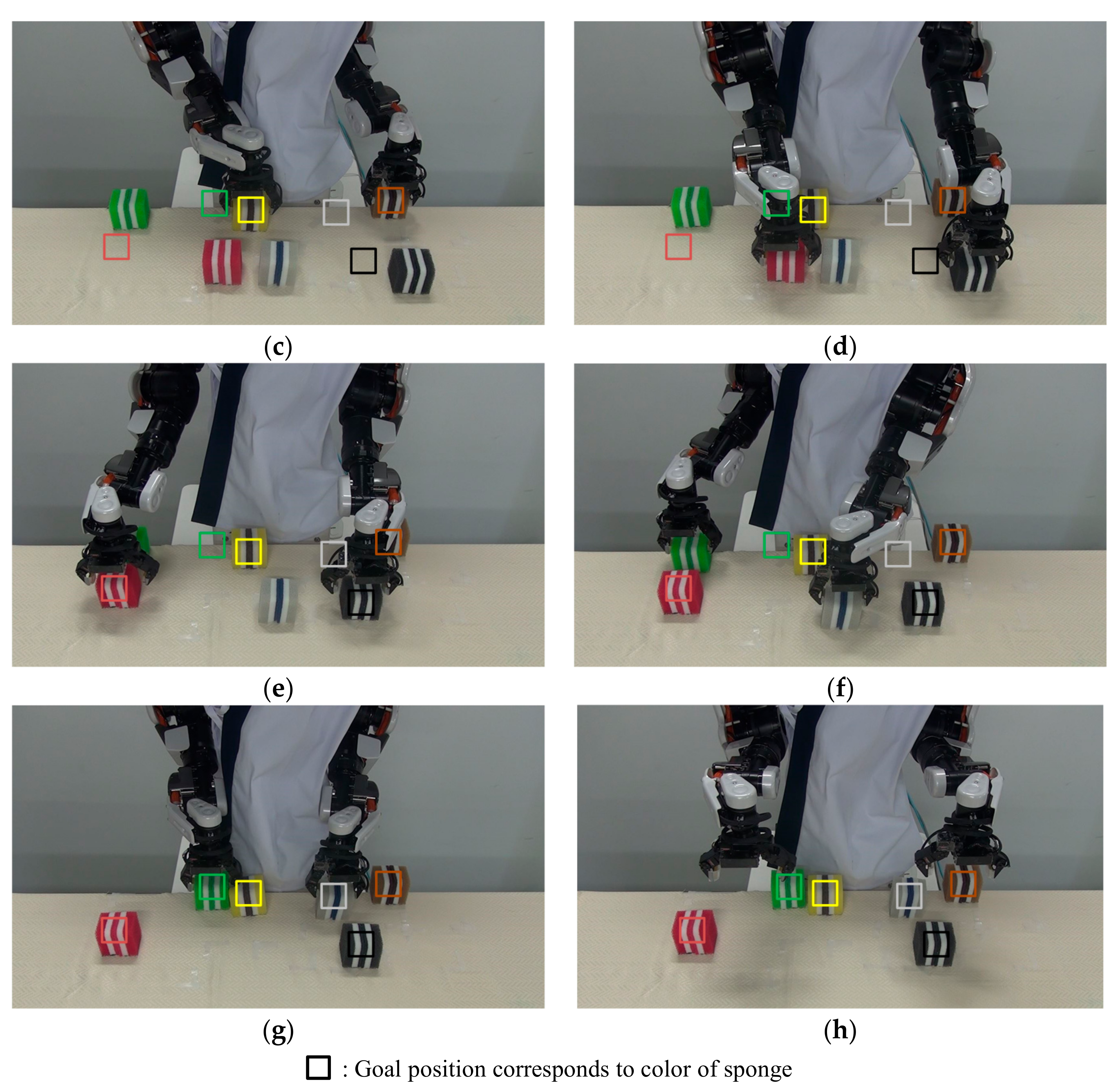
Figure 8.
Solution obtained by the proposed method in Experiment 2.

Figure 9.
Verification Experiment 2: (a) initial configuration; (b) picking the yellow and green blocks; (c) placing the yellow and green blocks; (d) picking the red and grey blocks; (e) placing the red and grey blocks; (f) picking the brown and black blocks; (g) placing the brown and black blocks; and (h) final configuration.


Figure 10.
Collision avoidance in Experiment 2: The path indicated by the red arrow, avoids the CA, and carries the object.
Figure 10.
Collision avoidance in Experiment 2: The path indicated by the red arrow, avoids the CA, and carries the object.


Table 1.
Simulation conditions.
| Object ID (Task) | Start Positions | Goal Positions |
|---|---|---|
| 1 | (0.32, 0.18) | - |
| 2 | (0.32, −0.18) | - |
| 3 | (0.30, 0.10) | (0.20, −0.01) |
| 4 | (0.35, −0.10) | (0.30, −0.30) |
| 5 | (0.45, −0.01) | (0.20, 0.12) |
| 6 | (0.41, 0.30) | (0.45, 0.18) |
| 7 | (0.23, −0.30) | (0.20, −0.15) |
| 8 | (0.35, 0.40) | (0.18, 0.30) |
Table 2.
Result of path length.
| Type of Path Length | Comparative | Proposal |
|---|---|---|
| Left arm | 1.69 | 1.35 |
| Right arm | 0.64 | 1.15 |
| Difference | 1.05 | 0.20 |
| Total | 2.33 | 2.50 |
Table 3.
Relationship between object ID and color.
| Object ID (Task) | 3 | 4 | 5 | 6 | 7 | 8 |
|---|---|---|---|---|---|---|
| color | yellow | red | grey | black | green | brown |
Table 4.
Solution obtained from MILP based planning. MILP: mixed integer linear programming.
| Type of The Arms | Comparative | Proposal |
|---|---|---|
| Left arm | 8→6→5→3 | 8→6→5 |
| Right arm | 4→7 | 3→4→7 |
Table 5.
Simulation conditions in Experiment 2.
| Object ID (Task) | Start Positions | Goal Positions |
|---|---|---|
| 1 | (0.32, 0.18) | - |
| 2 | (0.32, −0.18) | - |
| 3 | (0.15, −0.10) | (0.35, −0.14) |
| 4 | (0.32, −0.08) | (0.12, −0.20) |
| 5 | (0.30, 0.15) | (0.18, 0.00) |
| 6 | (0.25, 0.28) | (0.22, −0.02) |
| 7 | (0.35, 0.25) | (0.14, −0.05) |
| 8 | (0.20, −0.15) | (0.30, −0.28) |
Table 6.
Computation time ().
| n | Computation Time (s) |
|---|---|
| 6 | |
| 7 | |
| 8 |
© 2017 by the authors. Licensee MDPI, Basel, Switzerland. This article is an open access article distributed under the terms and conditions of the Creative Commons Attribution (CC BY) license (http://creativecommons.org/licenses/by/4.0/).
Share and Cite
MDPI and ACS Style
Kurosu, J.; Yorozu, A.; Takahashi, M. Simultaneous Dual-Arm Motion Planning for Minimizing Operation Time. Appl. Sci. 2017, 7, 1210. https://doi.org/10.3390/app7121210
AMA Style
Kurosu J, Yorozu A, Takahashi M. Simultaneous Dual-Arm Motion Planning for Minimizing Operation Time. Applied Sciences. 2017; 7(12):1210. https://doi.org/10.3390/app7121210
Chicago/Turabian StyleKurosu, Jun, Ayanori Yorozu, and Masaki Takahashi. 2017. "Simultaneous Dual-Arm Motion Planning for Minimizing Operation Time" Applied Sciences 7, no. 12: 1210. https://doi.org/10.3390/app7121210
Note that from the first issue of 2016, this journal uses article numbers instead of page numbers. See further details here.