1. Introduction
The positioning accuracy of a modern machine tool (MT) is one of the most important requirements to guarantee the machining precision and quality [
1]. The accuracy of a MT related to the geometrical deviations may depend up to 60% on the stability of the structure and for the rest on workpiece fixturing and tools [
2,
3,
4].
In the last few years, researches have addressed their studies to mechatronic systems with the intention of compensating these undesired effects [
5]. The principal causes of errors may be classified as geometrical errors and thermo-mechanical strains [
6,
7,
8,
9,
10]. The first group is represented as the shape deviation that disturbs the moveable slides of the MT and may be assumed to be independent to the time. The second class is the result of external factors acting on the frame which are fundamentally time-correlated.
This work focuses on temperature oscillations that can origin three-dimensional thermal grades in MT structures and can produce non-linear distortions over time, impacting significantly on the machine accuracy [
11,
12].
The thermal distortions of the device components are generated by temperature gradients existing inside the structure. In order to model the temperature spreading and to compensate the consecutive distortion, it is important to get the temperature mapping in real-time, in particular when ultra-high precision machining is required. Although thermal errors might be reduced by using structure materials with a low coefficient of thermal expansion, it is useful to consider a more reasonable method of decreasing thermal error such as an error compensation system. Recent studies have been carried out to introduce Polymeric Matrix Composite (PMC) fiber reinforced materials. Significant results related to mass reduction, stiffness increment, and damping increase have been achieved. Nevertheless, the growing of customer requirements in terms of cutting machine performances has pushed the designers to investigate novel solutions. Calibration is a method where the existing thermal deviations are compensated by correcting the position of the MT points based on the magnitude of the thermal-mechanical error.
The state of art shows many works in the field of thermal-structural error compensation [
13]. Researchers have developed various procedures such as a simulation method [
14,
15,
16] in modelling the thermal characteristics. Obtaining a mathematical representation can be a complex process because it is problematic to produce the edge limitations and get the characteristic of heat transmission. The test of the machine tool is still required to calibrate the model for a successful application of the technique. Different model structures have been used to calculate thermal errors such as Multiple Regression Analysis (MRA) [
17], artificial neural networks (ANN) [
18], fuzzy logic [
19], an adaptive neuro-fuzzy implication [
20,
21], and a grouping of diverse modelling procedures [
22,
23]. Early work by Chen et al. [
15] used both a MRA model and an ANN model for thermal error compensation of a horizontal machining center. Thanks to their experimental results, it was possible to decrease the thermal error from 200 µm to 30 µm.
Wang [
22] applied a Hierarchy-Genetic-Algorithm (HGA) trained neural network with the aim of mapping the temperature change against the thermal response of the MT. Experimental results pointed out that the temperature inaccuracy model could moderate the deviation to smaller than 10 µm under real conditions. Nowadays, there is a number of different approaches to solve this problem [
22], which can be grouped in two main categories: design-based techniques and compensation-based methods. The first category collects all those good practice design techniques that permit the development of a MT based on a structure that is stable, stiff, and able to damp vibrations, thereby limiting excessive thermal gradients. The second category refers to those technologies that continuously predict and compensate the positioning error throughout the application of suitable sensors and models of the MT structure, implemented into the machine center software.
This work presents a novel active approach that focuses on this second category. The approach consists of developing a new class of “smart adaptronic structures” based on the integration of passive materials, Carbon Fiber Reinforced Polymers (CFRP), with sensing materials (smart sensors) able to measure the deformed conditions of the structure in real-time and to calculate the transposition at the end-effector through an appropriate thermo-mechanical model.
The proposed solution is based on the use of a multiplexed optical fiber sensor with a sufficient number of Bragg gratings for measuring strains (in specific reticular grid points) embedded in the structure. The high sensitivity of the sensors (~0.2 με) suggests their potential use for MTs with very stiff structures. These smart sensors (FBG) are suitable to measure both strains and temperature with very high accuracy and resolution [
22]. Then, the measurements (linear elongations) obtained by these sensors are post-processed to predict the distortion/deformation of the structure (at tool tip location) in the 3D space domain using special algorithms based on the Multiple-Regression Method [
23]. The FBG sensors are embedded in the structure, this choice allows for improved accuracy in detecting any deformation due to thermo-mechanical disturbances. A multi-regression model is developed and presented to compensate the MT errors at the tool tip point (TTP). This model has been validated through a set of simulations and tests and improved by including a number of independent variables. In particular, this study aims to present a novel lightweight structure based on hybrid materials to damp mechanical vibrations, and an effective real-time system able to compensate thermo-mechanical errors by direct feedback.
State of art presents a number of works that deal with the application of FBG sensors in order to detect thermal errors. Huang et al. [
24] illustrate a study for measuring the real-time temperature field of a heavy-duty machine tool based on fiber Bragg grating sensing technology. In this work, the FBG sensors are installed in different locations of the MT (e.g., frame, spindle, spindle housing, gearbox, and motors) in order to measure thermal effects. The study demonstrates that the surface temperatures and spindle thermal errors have a similar change trend following the ambient temperature. In the same way, Liu et al. [
25] presented a study to detect MT thermal deformations using FBG sensors. The study highlights that FBG sensors may be used for the measurement of conventional machine tool deformations, showing the high potential of FBG sensors. Both studies focus on the thermal error measurement using the FBG feedback, nevertheless an accurate MT compensation model is not developed. Instead, Bosetti et al. [
26] propose a complex reticular structure based on FBGs associated with a computation algorithm that allows for the reconstruction of the displacement field. A recent interesting work has been developed by Abdulshahed et al. [
27]. This study shows a new modelling methodology for compensation of the thermal errors. In particular, the proposed model is based on Grey system models, artificial neural networks (ANNs), and a Particle Swarm Optimization (PSO). To improve the accuracy of the predicted model, four laser displacement sensors and feedback information supplied by FBGs were used.
2. Concept and Kinematic Model Formulation
The proposed system is the first phase of an innovative concept to compensate dynamic variations in machine tools. This configuration does not measure the origins of deformations (temperature, load, and accelerations), but it determines the distortions of the MT structures and compensates for them using a proper robust model.
2.1. Working Principle
In order to extrapolate deviations and calibrate the MT, a set of Fiber-optic Bragg Gratings strain sensors (FBG) are embedded in the vertical axis [
28]. FBG sensors may offer many advantages since they ensure a dynamic performance up to 260 Hz [
28], permitting the exposure and measurement of distortions acting during working operations. The determination of the tool tip displacement is a complex process if it is directly extrapolated from the strains. For this reason, it is more convenient to employ FBG as a displacement sensor and to measure the overall elongation (integral effect) of some critical point-to-point dimensions of the MT geometry.
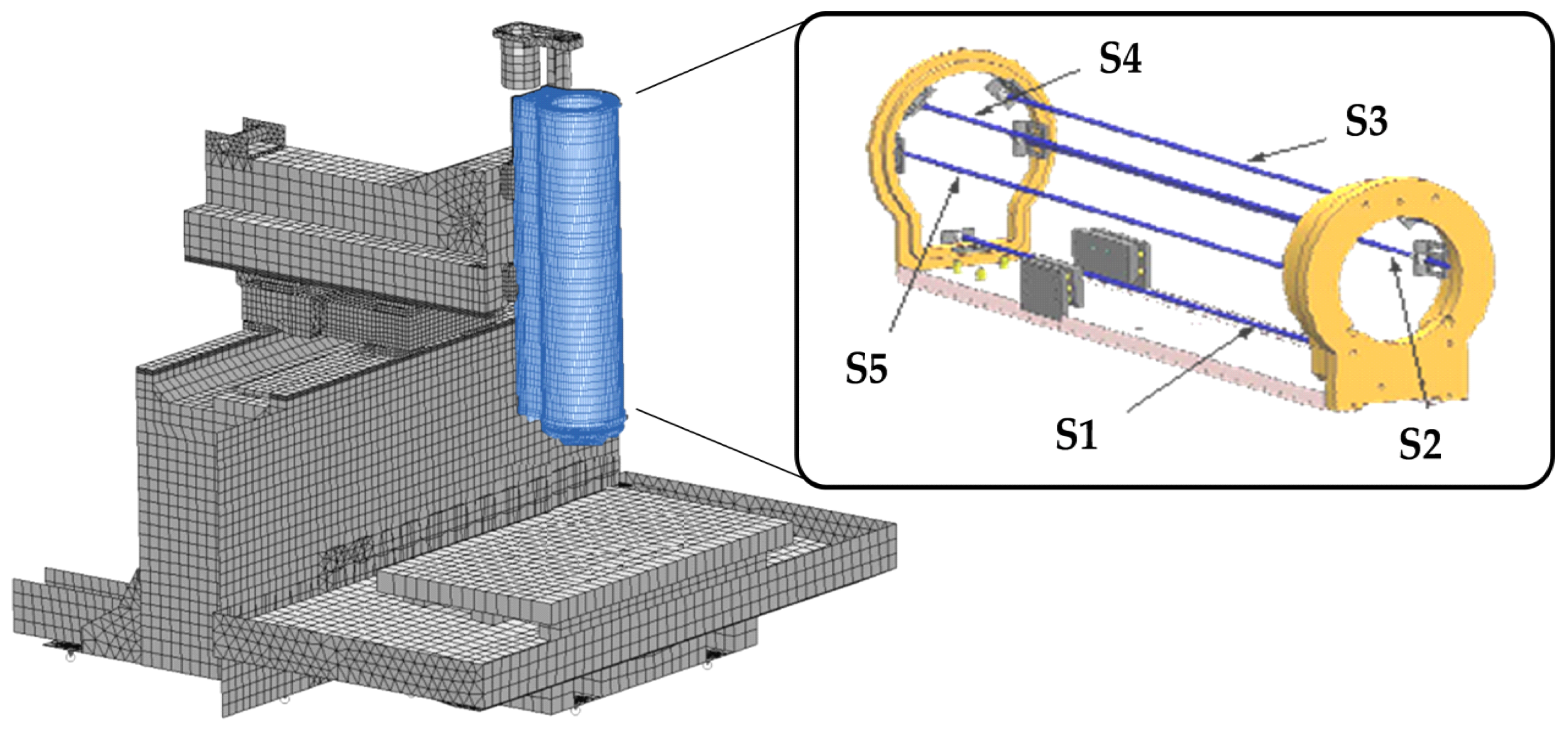
The proposed adaptive structure consists of an innovative machine tool vertical axis made of CFRP material, which integrates a set of the fiber Bragg grating (FBG) displacement sensors (S1–S5), as shown in
Figure 1. The FBG sensors have been placed in the vertical-axis structure in order to measure the total axial elongation of each side of the structure in the direction of the fibers’ orientation, combining static loads and thermal gradients. These on-line measures are used as input in a structural mathematical model that predicts the deviation of the tool tip in three spatial directions. The outcome is an algorithm, represented by linear equations, that is integrated into the computer numerical control (CNC) to compensate the position of the tool tip in real-time during the working operations. The coefficients of the prediction models were calculated using a Multiple Regression Analysis (MRA). The model was built by simulation of the Finite Element Analysis (FEA) applied to the ram that was subjected to different static loads and thermal conditions.
The working conditions have been simulated through a set of loads representing the undesired factors during the machining. Finally, the model has been validated through a set of experimental tests on a prototype in order to prove the effectiveness of the FBG sensors.
2.2. The Embedded Distributed Sensors
Accurate and reliable measurements of the key variables play an important role in compensating for deviations and in calibrating the MT. The information obtained by these variables are considered for model validation and MT error compensation. The temperature sensors are used as inputs to estimate thermal deformations [
29,
30]. The spindle speed, the axis feed-rate, the machining time, and other constants may be the main causes of heat sources.
A traditional approach is based on the temperature distribution evaluation using thermocouples or resistance thermometers [
31,
32]. This method may show a set of limits, in fact when the number of thermocouples increases on the MT surface, many potential undesired effects may be noted (e.g., electrical disturbs), thereby reducing the effectiveness of the calibration method. On the other hand, a limited number of sensor applications does not permit an accurate mapping of the temperature behavior. Nowadays, infrared technologies may be an effective option to measure the thermal gradient on the surfaces of the MT frames [
33,
34]. In fact, these systems are able to provide robust measurements of temperature. Nevertheless, they lose information when the system is switched off, compromising the compensation over time.
The FBG strain sensors are able to overpass all these limits; in fact they guarantee robust and permanent measurements and they may be installed in multiple positions embedded in the MT, mapping potential thermal gradients completely. In addition, the FBG sensors have the capacity to detect all potential deviations on the tool tip point (TTP), not only originated by temperature variability, but also when other external factors (e.g., cutting effects) are present. In fact, they may measure directly all point to point deviations of the MT structure surfaces [
35].
In particular, FBGs are usually insensitive to magnetic and electric inputs. Certain types of optical fibers have high sensitivity on specific wavelengths. Their photo-sensitivity can lead to a variation of refractivity when the fibers are open to a specific wave-length (UV range). Other advantages of FBG sensor application are represented by their lightweight, small size, electromagnetic protection, distance conduction, and electric inaccessibility [
36,
37]. These characteristics are particularly suitable in manufacturing conditions. In addition, this technology shows multiplexing capabilities, providing an absolute measure of strain at multiple points simultaneously [
38,
39].
The state of art shows a broad range of FBG applications. They are used to detect damages, to monitor structure health, to control stresses in airplanes and rotor blades of wind turbines, or to measure strain in harsh environments [
40]. By using these sensors, the modelling process can become simpler, more robust, and more efficient, since the number of sensors can be limited and the effects of thermal hysteresis minimized. Zhou et al. [
41] used FBG to investigate the effect of temperature variations of a machine tool on the shop floor. The FBGs work as an optical filter by selecting a certain portion of the input spectrum of the light to be reflected. They are integrated as sensors in optical fibers. When the part of the FBG sensor is deformed due to external disturbances (e.g., strain or temperature), a change in the grating periods is noted modifying the Bragg wavelength. By measuring the wavelength change, the physical quantities can be measured and the temperature effects should be compensated using a proper system. In this way, a FBG sensor is based on the alterations in the reflective signal, which depends on the core and the periodicity of the grating.
The Bragg wavelength is defined as [
41]:
where
neff and ∆ are the refractive value of the material and the grating structure, respectively. As defined, under temperature or stress influence, the grating dimension changes. The Bragg length shift of ∆
is modulated by axial deformation change ∆
ε and temperature range ∆
T in the form:
where
is the FBG wavelength, and
pe, and α
f are the photoelastic coefficient and the thermal-expansion value, respectively. The relationship between the temperature fluctuation and the FBG sensor is expressed by the following equation:
By using Equations (2) and (3) the temperature effect to be compensated may be extrapolated.
2.3. Kinematic Linear n-Sensor Model
Considering a CFRP structure (e.g., a beam) connected by
n ideal bars and subjected to a plane in-deformation, and assuming that the maximum allowable displacement range is smaller than 1 µm, the movement δ
L of two connected sections can be expressed as:
where
Li represents the instantaneous length of the
i-th bar and
Li,0 is the distance of the
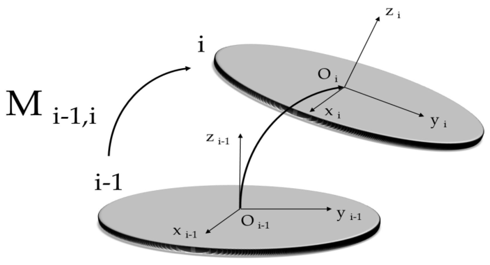
i-th segment, respectively. The relationship between distortions and FBGs’ movements can be modeled as shown in
Figure 2. The actual end effector position includes the effect of kinematic errors, achieved by the composition of three roto-translations. These matrices are defined by Equations (5)–(9).
where matrices
Ma,
Mb, and
Mc elements are exhaustively described in [
41,
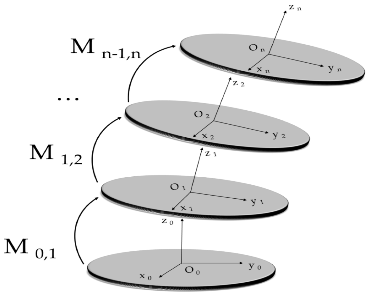
42]. By considering a vertical slide as a series of elementary parallel manipulator systems, as shown in
Figure 3, it is possible to generalize the kinematic model for micro-deformation measurements.
In particular, the error and the compensation system of MT can be represented by Equation (9).
where the matrices represent the three subsequent functions to transfer the tool tip point of MT from the position (0; 0; 0) to the position (
x;
y;
z). The tool tip point (TTP) is one of the most interesting points in a MT, in fact it represents the ideal contact point between the tool and the workpiece. Any undesired displacements at TTP may generate the machining errors.
A calibration model has been developed to compensate the thermal effects. The nominal TTP position (
x;
y;
z) can be appropriately stated using the transformation matrix formalism as follows:
where the error spatial components are expressed by Equation (11).
δLj is the elongation measured by the sensor j (j = 1, ..., 5). These errors can depend on the position of the vertical axis along the z-direction.
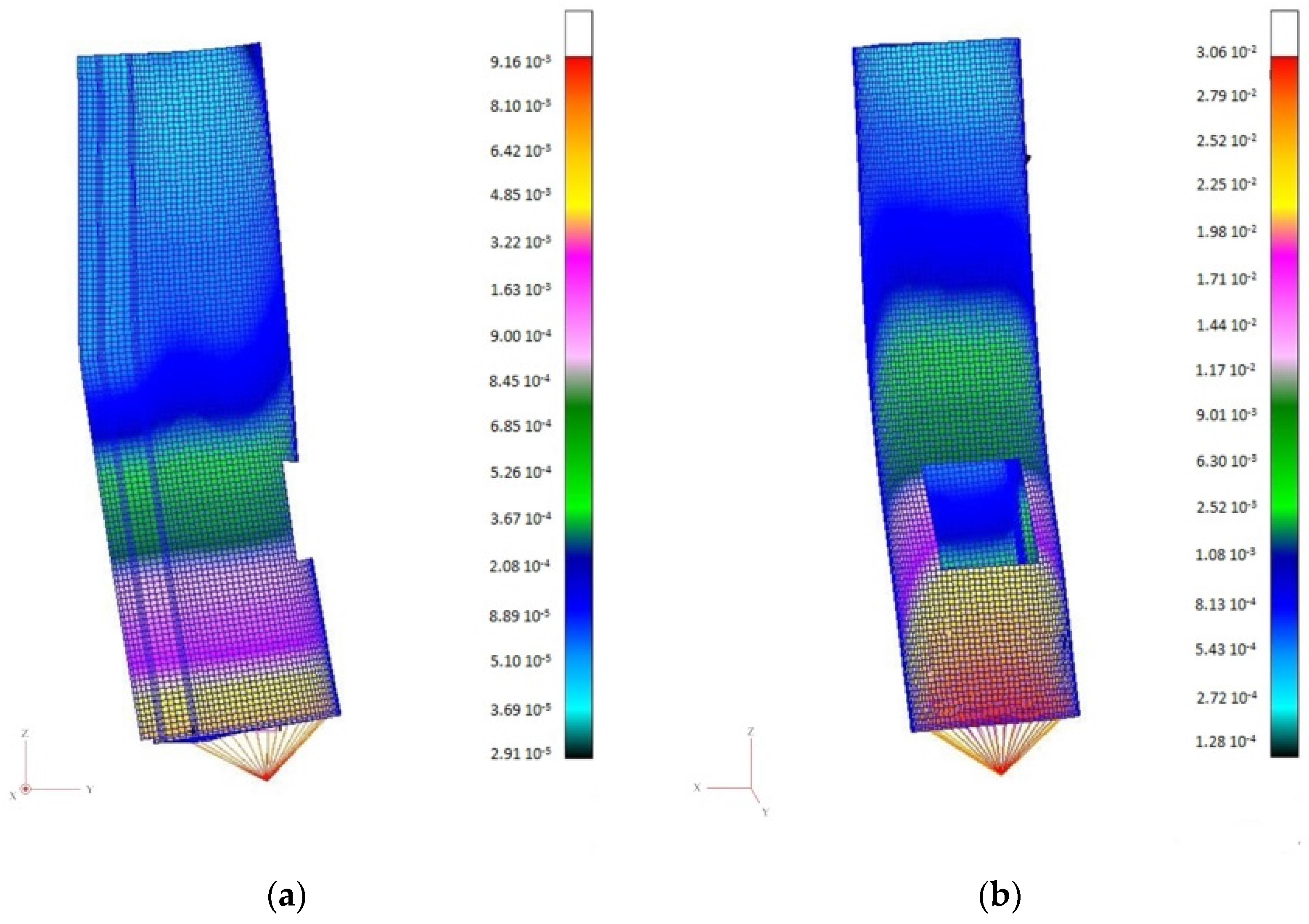
In order to investigate the feasibility of the FBG sensor implementation, the first phase was to study the machine tool behavior through a set of simulations. A model may be built by a Finite Element (FE) analysis that represents the main MT features, focusing on structural parts and sensor positions. The study was performed on a ram of a milling machine and the simulation results are shown in
Figure 4. The FE analyses were executed simulating a set of ram configurations applying a static load on
x-,
y-, and
z-axes.
Figure 4 illustrates an example of the simulations obtained from the FE analysis applying a static load (2000 N) on the
x-axis (
Figure 4a) and the
y-axis (
Figure 4b). The results showed that the main critical directions were the
y-axis (max-displacement close to 30.0 μm) and the
x-axis (max-displacement < 10.0 μm), while the structure highlighted a high stiffness in the
z-axis (max-displacement < 1.0 μm). The simulation was used to estimate the coefficients of the regression equations.
In the same way, the FE analysis was replicated considering the thermal stresses. The objective was to simulate and measure the displacements in different parts of the structure where the FBG sensors were located. By using this information, a further adjustment of the regression model was executed in order to predict the TTP position accurately.
2.4. Test-Bench Setup Validation and Procedure
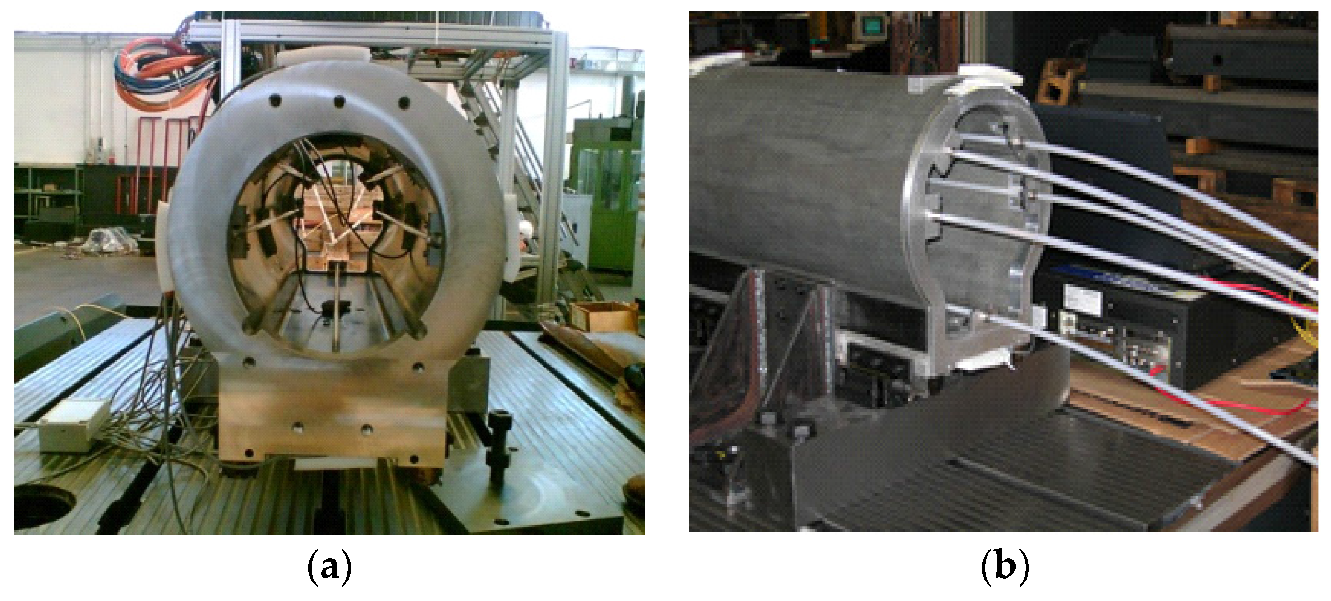
In the light of the obtained results from numerical simulations, a prototype (a milling machine ram) was fabricated and tested. The scope was to compare the numerical models with the experimental tests using the FBG sensors.
Figure 5 shows an overview of the system prepared to perform the experimental tests. The test-bench was composed of the moving slide frame with the embedded FBG sensors, the interrogator, and a personal computer to process the collected data. The axis structure was constrained in
x-
y directions at the carriages location and in the
z direction at the nut support location. The selected FBGs had the following characteristics:
peak resonance wavelength of 1549–1551 nm,
length of active zone from 0.25 k mm to 10 k mm,
length of passive zone from 1 m to 100 m,
reflectivity close to 90%,
peak amplitude equal to 15 dB,
temperature sensitivity of 10.2 pm/°C,
measurement precision lower than 0.2%,
measurement resolution less than 2 μm,
Range Measuring System of operating temperature from −50 °C to +110 °C.
The experimental procedure consisted of two main phases. In the first part of the test campaign, a set of static loads was applied to the structure in order to verify the effectiveness of the FBG sensors embedded in the prototype. These results were compared with the numerical model.
The stresses measured by the FBG sensors through the modification of their characteristics were transferred to a PC. The signals were examined and saved by the sensing software. The obtained results were used in order to improve the regression model to compensate the TTP deviation.
The second phase of the experiments was based on the time-variant thermal tests. In this case, the experimental tests were performed by varying the temperature of the structure over time (36 h). This part of the study sought to optimize the model and understand the effectiveness of the system in compensating the TTP position when the MT structure temperature varies.
The measures of the FBG sensors were acquired by an optical reading unit (Fabry-Perot Interferometer), while the temperature changes of the MT ram were automatically collected by integrated circuit temperature sensors (LM35) located along the structure. A FBG interrogator was adopted to monitor the Bragg wavelength shift of the FBG under different stresses. It had a resolution of 1 pm and a sampling frequency of 1 kHz. In particular, two laser sensors were used to measure the TTP displacement. An auxiliary low conductive kit was used to represent the tool and tool-handler system. It was fixed to the bottom flange of the ram. The laser sensors were placed at 120 mm from the assigned tool tip point, measuring both displacements in the x-axis and y-axis directions. The laser sensor had a resolution up to 0.05 µm and a linearity of 0.5 µm.
3. Experimental Tests and Results
The compensation of thermal-mechanical errors is based on an effective kinematic model that is able to represent the potential point to point deviations due to external generalized loads (in this case, mainly temperature). Usually, the thermal strains are a supplementary component that is summed to the geometrical errors when there is a variation of the structure temperature gradient. For this reason, the mathematical model needs to be expressed as follows:
where
A1 is the coefficient vector and
A2 is the matrix of the regression model, while ∆
T represents the temperature intensification vector of the frame. In order to tune the model, a stepwise regression with a programmed exploration algorithm was applied. This technique is able to categorize linear formulations at each stage counting or removing a factor using ANOVA or other techniques. The experimental campaign considered the results of a set of tests performed in static and dynamic conditions. In the first case, the model was validated by applying a static load to TTP, while in the second part of the research the model was evaluated while the thermal conditions varied. In both cases, the model was analyzed by comparing the predicted deviations with real measurements of the TTP positions.
3.1. The Static Experimental Tests for Model Validation
The first campaign of experimental testing was performed by applying a set of static loads to the tool tip points. These tests aimed to verify the model obtained by the numerical analysis. In particular, by using the experimental results it was possible to improve the estimation of the equation coefficients to calibrate the system.
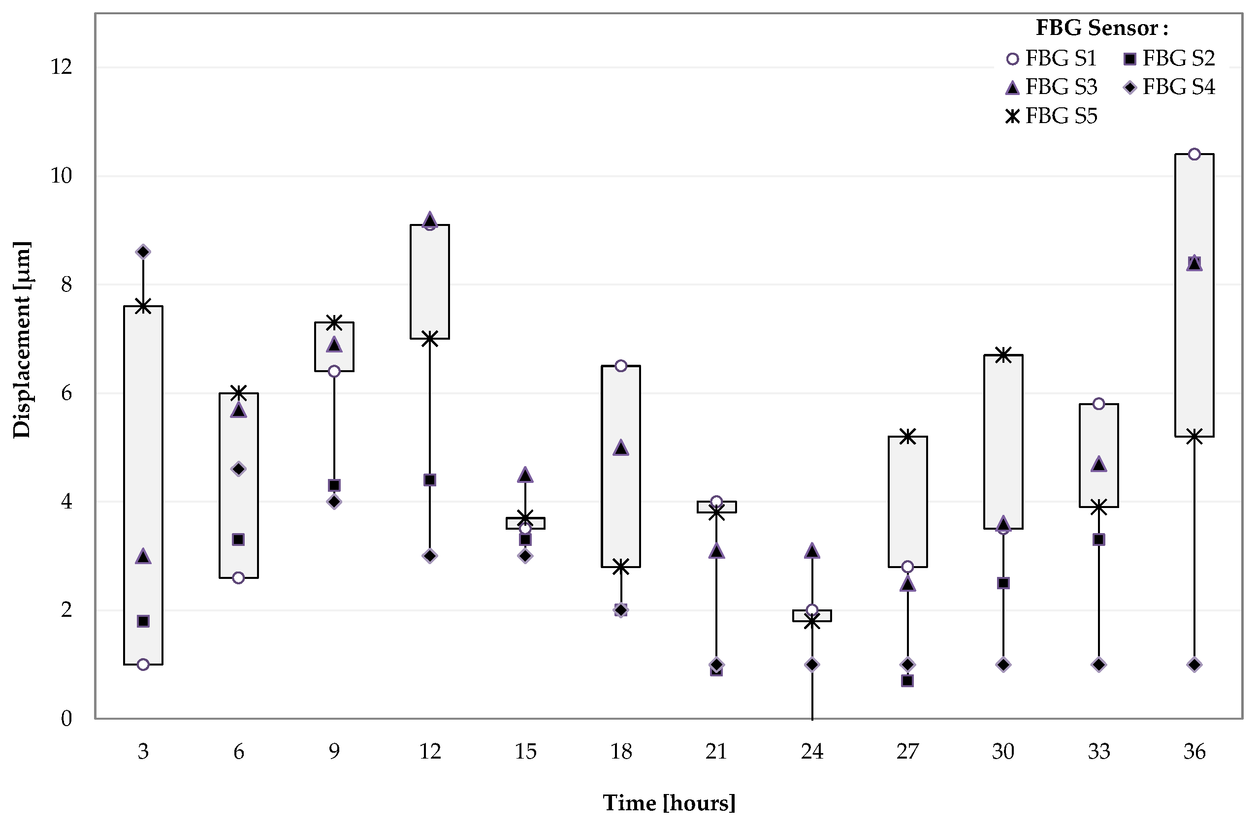
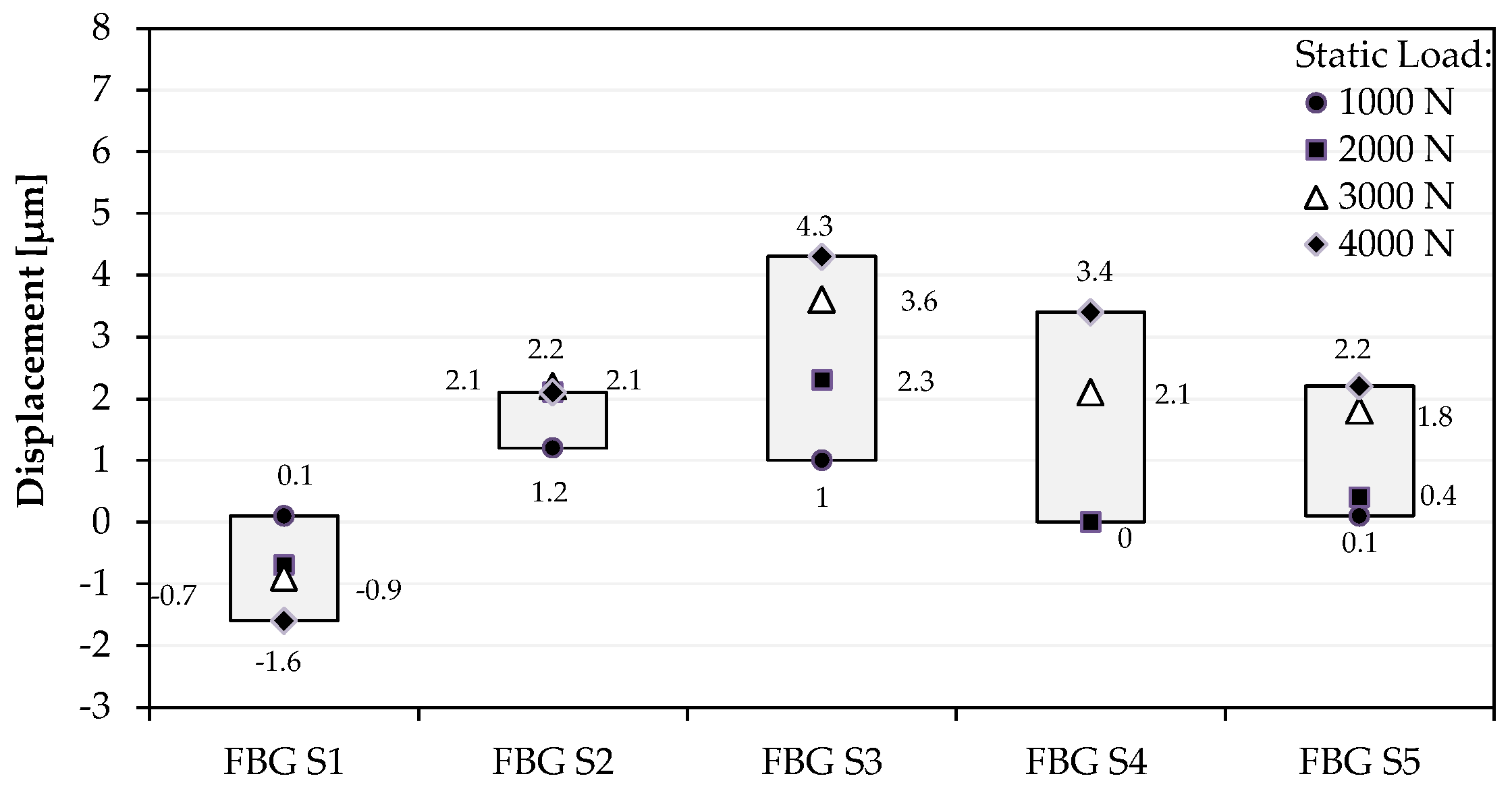
Figure 6 shows the displacements (μm) measured by the FBG sensors when a set of static forces (1000 N–2000 N–3000 N–4000 N) were applied to the tool tip. In particular,
Figure 6 illustrates the variability of the displacements detected by the sensors that were located in different positions on the ram surface. This variability highlights the relationship between the sensor positions and the magnitude of the applied loads.
The position of each FBG sensor is critical for detecting the stress measured on the MT frame. As defined, an increase of the sensor number does not have a significant impact on the material isotropy.
The first validation campaign was conducted by applying a set of static forces at TTP and comparing the real tip displacement measured by an interferometer with the predicted position defined by the model prediction equations, as shown by Equations (10) and (11).
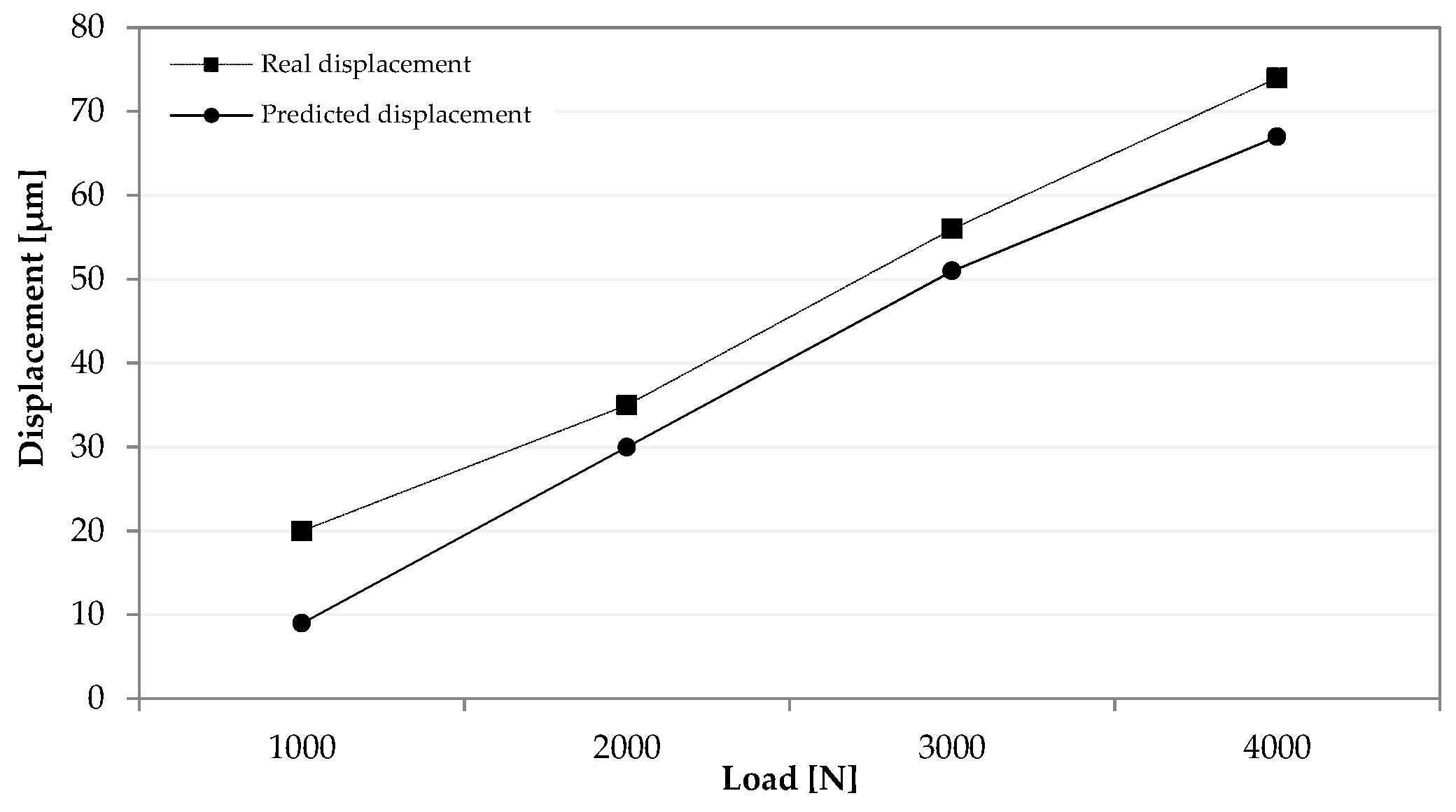
Figure 7 presents the comparison between the real and the predicted displacement (
y direction) of the tool tip point by varying the static load.
The obtained results show a substantial matching between the real and predicted positions. In particular, the model has an acceptable accuracy that is close to 5% in the load range (1000–4000 N).
3.2. The Time-Variant Experimental Tests for Model Validation
In the second part of the experimental campaign, a set of time-variant experiments was executed. In particular, the prototype was subjected to the application of thermal loads over a prescribed time period of 36 h. By starting with an environmental temperature close to 30 °C, the frame conditions were monitored by measuring the thermal stresses in the different positions of the frame surface. A preliminary investigation allowed for the improvement of the regression coefficients extrapolated from the FE study in order to obtain a robust model of the thermal effects. In this way, a multivariate regression model was studied to fit the z-axis thermo-mechanical deformations.
Figure 8 presents the displacement variability detected by the sensors during the experiment time. The temperature of the structure was automatically collected by integrated circuit temperature sensors (LM53) located along the ram.
By using the experimental data, a Multi Regression Analysis was performed, estimating the thermal-mechanical model coefficients. In addition, further temperatures of strategical positions (∆Tbulk, ∆Tsurf, and ∆Tflange) were collected by a set of thermocouples and included in the model as independent variables.
Equation (13) represents the mathematical formulation of the MRA technique.
where ∆
Tbulk is the variation of
z-axis bulk temperature between the starting time and the instant of measure, ∆
Tsurf is the difference between bulk RAM temperature and Surface temperature, and ∆
Tflange is the temperature range measured between the spindle case and the structure.
Table 1 summarizes the results of the MRA model with the use of a stepwise software.
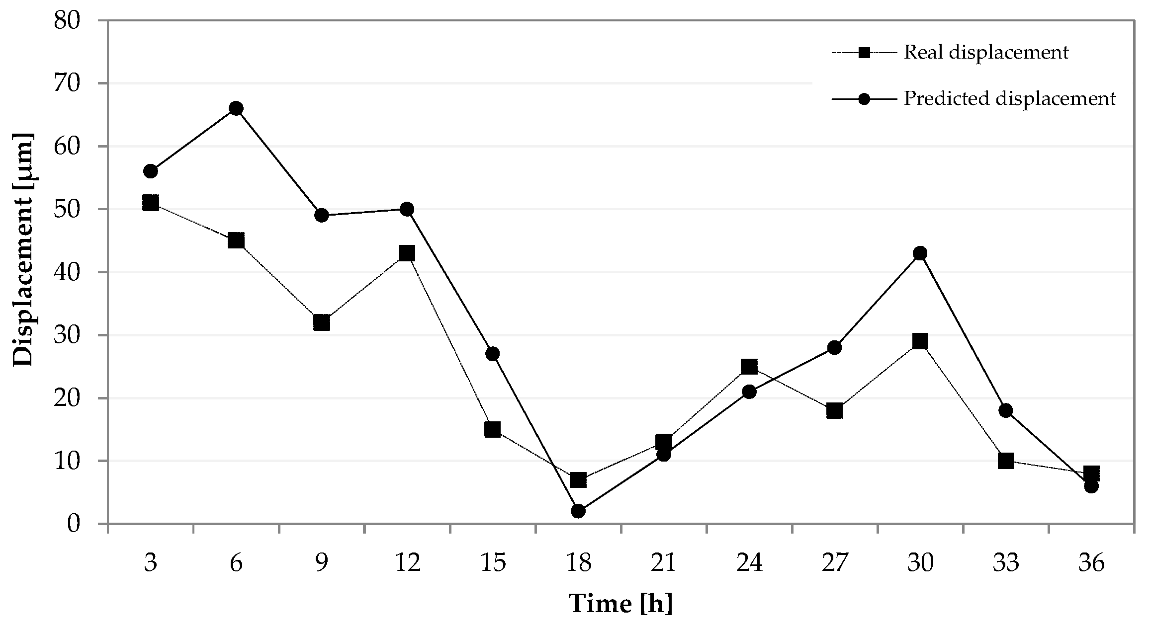
Figure 9 presents the thermal study results. A substantial coherence between the real and predicted position of the tool tip point is noted over time (36 h). The curves have the same change trends. The MRA models is able to fit the thermos-mechanical deformations with some mismatching due to the limited number of sensors integrated into the structure. The obtained accuracy of the predicted model varies from 5% to 8%, guaranteeing a substantial effectiveness of the model to predict the tool tip deviations. In the proposed experiments, the temperature effects had an important influence on the TTP position, in fact the maximum detected deviation was equal to 51 microns. If compensation is not provided, the total error due to the thermo-mechanical effects is described by the dotted curve in
Figure 9. By using the predicted model the TTP position may be corrected. The potential compensation is equal to the difference between the dotted line and the solid line in
Figure 9. In this case, the maximum model error is close to 9 microns. The presented model is particularly valid for external loads lower than 1000 N, as shown by conventional machining (e.g., milling cutting forces or temperature gradients). In this configuration, the rotations are considered as displacements, assuming the small displacement hypothesis. This paper also presents a set of simulations and tests based on loads that are over the expected operational range. This choice allows for the investigation of all potentialities of FBG technology applied to a novel MT structure made of CFRP and for the evaluation of further utilizations when high external loads are present.
The obtained results underlined the effectiveness of the FBG sensors in detecting the structure stresses due to external loads (e.g., temperature variation). The application of FBG sensors shows many advantages, in particular, they are able to measure stresses from different types of sources (e.g., load, temperature, accelerations) in real-time. This fact allows for the ability to obtain a model that is able to predict the TTP position when any type of stress occurs on the MT structure. On the other hand, the model needs to be optimized in order to reduce the predicted errors, increasing the number of sensors and improving the regression technique.
Table 2 shows a summary of the main advantages and limitations of the FBG sensor application.
4. Conclusions
This study aims to present a structured method to compensate errors of a MT when it is affected by undesired external factors. This point is a critical process since it allows for the instantaneous compensation of geometrical or thermal errors, thereby guaranteeing the machining performance. The conventional approaches are based on models that are able to predict the MT deformations, studying a relationship between machine accuracy and undesired loads. Nevertheless, it is difficult to identify a general robust relation and these models need to be calibrated for every machine variant, thereby limiting their success, and increasing both costs and the implementation time.
The proposed solution is based on a novel approach to calibrate a machine tool in real-time, analyzing the thermo-mechanical errors through fiber Bragg grating (FBG) sensors embedded in the MT frame. This configuration consists of an adaptronic structure of passive materials, Carbon Fiber Reinforced Polymers (CFRP), equipped with FBG sensors that are able to measure in real-time the deformed conditions of the frame. By using a proper thermo-mechanical kinematic model, the displacement of the end effector may be predicted and corrected when it is required. By starting from a set of FE simulations, a relationship between the FBG behaviors and TTP displacement was evaluated. The simulations were performed by varying a static load at TTP and the structure temperature. The multiple regression allowed for the identification of a model to be validated through a set experimental tests. A prototype (a ram of a commercial milling machine) was fabricated integrating the FBG sensors in the MT frame. In the first part of the experimental tests, the model was validated applying a set of static loads. This analysis showed a good matching between the real and the predicted position of the MT tool tip point. In the same way, the tests were replicated varying the environmental temperature over time (36 h). The results obtained from the FBG measurements allowed for the regression model to be tuned and for the error prediction to be improved. The last campaign of experimental tests illustrated a substantial coherence between the real and predicted position of TTP. This study highlights the significant advantages of applying FBG sensors in measuring MT deformations, such as their high sensitivity, geometrical versatility, light weight, immunity to electromagnetic interference or chemical agents, and high durability. Nevertheless, it also underlines the limitations of this method. In particular, the accuracy of the model depends on the number and the position configuration of the sensors implemented in the structure. The choice of specific statistical methods may improve the accuracy of the model. In the light of these results, the next steps of the research will be based on the fabrication of new prototypes changing the position configuration of the FBG sensors. The collected data will be analyzed by further techniques to reduce the model error.


 ,
, 


