1. Introduction
Regenerative thermal engines have various advantages, such as high efficiency, low noise production, and small vibrations, which enable wide application prospects in power engineering and energy utilization. One of the crucial components of a regenerative thermal engine is the heat exchanger working in oscillating flow [
1]. The heat transfer performance of the heat exchanger directly determines the efficiency of the whole system. In order to improve the thermal efficiency of the oscillating-flow heat exchanger, it is necessary to study the dynamic heat transfer characteristics and the factors influencing the gas flow in heat exchangers. The optimization of the geometrical structure and working parameters of the oscillating-flow heat exchangers, can provide theoretical guidance for the design of highly efficient regenerative thermal engines.
According to the significant differences between the oscillating and steady flows, researchers have proposed a variety of methods for characterizing the heat transfer of an oscillating-flow heat exchanger. In 1967, Richardson [
2] proposed an experimental correlation of steady-state flow in a cycle, in order to approximate the characterization of oscillating flow heat transfer, which is called the time-averaged steady flow equivalent (TASFE) model. Based on thermoacoustic theory, Nika et al. [
3] mathematically developed the Nusselt number characterization method in the complex field. In 1986, Gedeon [
4] was the first to verify the rationality of using averaged parameters of space and cycle in the momentum and energy equations. This method doesn’t require an accurate measurement of the phase difference between the heat transfer temperature gap and the heat flow. In 1996, Zhao and Cheng [
5] studied the heat transfer characteristics of oscillating gas in a circular copper tube heated by constant heat flux. The average Nusselt number was correlated with the dimensionless amplitude and frequency, obtaining a preliminary empirical correlation. In 2007, Nsofor et al. [
6] carried out a study on the heat transfer characteristics of the oscillating-flow heat exchanger, measuring the heat transfer in a finned-tube heat exchanger. Jaworski and Piccolo [
7] obtained the temperature and velocity fields in a parallel plate channel heat exchanger, using the planar laser-induced fluorescence (PLIF) technique, combined with the particle image velocimetry (PIV). The relationship between the Nusselt number and the Reynolds number was thus obtained. Recently, Jaworski’s group investigated the effect of fin length and fin spacing on the thermal performance of finned-tube heat exchangers [
8]. The heat transfer rate can be predicted using the correlation between the heat transfer effectiveness, and the normalized fin spacing and fin length. In the past decade, researchers have been approaching a deeper understanding of the oscillating flow behaviors, using state-of-the-art techniques [
9,
10,
11,
12,
13,
14].
Tang et al. [
15,
16] experimentally studied the influence of working conditions, as well as the compression-expansion effect, on the Nusselt number of finned heat exchangers. An empirical correlation of the Nusselt number, with the maximum Reynolds number and Valensi number, has been summarized. Following the analysis and optimization method, this work aims to introduce the geometrical parameters as major factors of the heat transfer performance prediction. It presents an empirical correlation for the finned heat exchanger working in oscillating flow, which comprehensively considers velocity amplitude, oscillating frequency, pressure ratio, and geometrical dimension during the heat transfer process. In the following discussion, the dimensionless parameters are defined as:
where
uA and ω are the velocity amplitude and angular frequency of the flow, respectively.
h is the mean convective heat transfer coefficient. ν and
k are the kinetic viscosity and thermal conductivity of the fluid, respectively.
dh is the hydraulic diameter.
For the cross-section shape of the flow channels in fin-type heat exchangers, the geometry primarily depends on the channel length
l and hydraulic diameter
dh. In the design of heat exchangers working in oscillating flow, the length direction, parallel to the direction of oscillating fluid, is constrained by the gas peak-to-peak displacement. The transverse dimension, perpendicular to the direction of oscillating fluid, is limited by the thermal penetration depth δ
k, which is defined as:
where ρ
m and
cp are the mean density and the isobaric specific heat of the fluid, respectively.
Swift [
17] pointed out that the relative displacement amplitude has an important effect on the heat transfer performance. The relative displacement amplitude
Ar is the ratio of the peak-to-peak displacement value and the channel length, which is defined as follows:
where
xA is the displacement amplitude of the flow. Hofler [
18] and Piccolo [
19] suggested that the
Ar value should be close to, or larger than, one. In fact,
Ar is not an independent geometrical parameter and can be practically transformed into an expression, including the dynamic parameters, as follows:
Equation (6) indicates that the influence of geometrical parameters on heat transfer performance can be discussed in relation to the controlled working conditions. As a geometrical parameter of the heat exchanger, l/dh can be correlated as a major factor when considering the heat transfer characteristics.
Following the work presented in Reference [
15], this paper presents an experimental study using six different geometrical dimensions of finned heat exchangers with parallel plates, in order to analyze the impacts of fin length, plate spacing, and corresponding relative fluid displacement amplitude, under various working conditions. This is completed in order to propose a comprehensive empirical correlation for the finned heat exchangers with parallel plates working in oscillating flow, displaying a wider range of application.
2. Experimental Methods
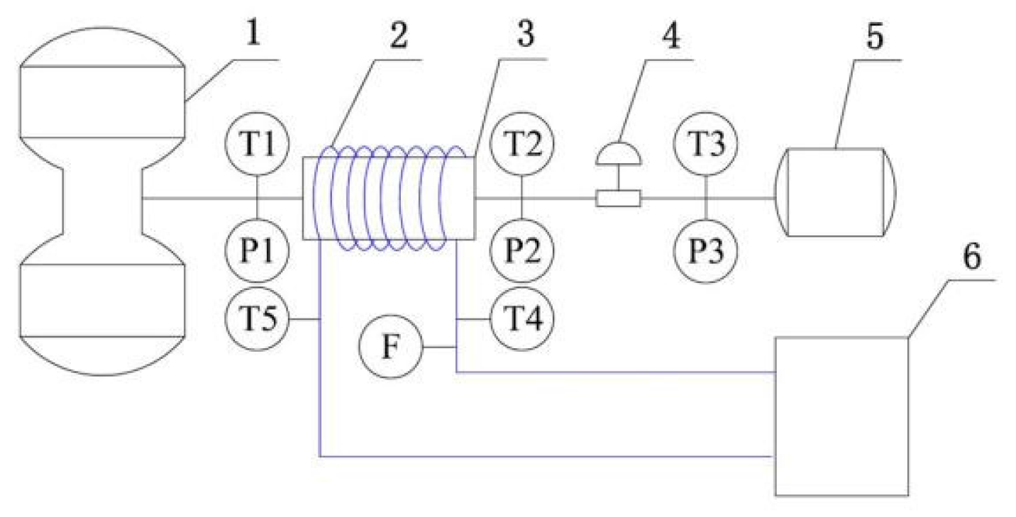
In order to simulate the actual working conditions of heat exchangers in regenerative thermal engines, an experimental setup is established to measure the heat transfer characteristics of the finned heat exchangers with oscillating flow conditions. The working fluid is helium.
Figure 1 presents the schematic diagram of the experimental setup, and more details can be found in [
15].
A linear compressor (Manufactured by Lihan Thermoacoustic Technologies Co., Ltd., Shenzhen, China) is used to generate pressure wave in oscillating flow. The compressor is driven by variable-frequency power supplies so as to indirectly control the oscillating frequency of the flow by adjusting the frequency of the compressor. The input work of the compressor is controlled within 2.5 kW and the operating current is controlled below 11 A. A variable-frequency power supply allows the voltage and current limits to be set according to load characteristics required by programmable logic controllers. A frequency range of 0 Hz to 650 Hz, and a resolution of 0.01 Hz, are accessible. The combination of an adjusting valve and a gas reservoir structure is used to control and measure the velocity amplitude of the flow. More specifically, for oscillating flow, the adjusting valve and the gas reservoir can be analogous to resistance and capacity impedance, in series with the required values achieved by changing the valve opening, which controls the velocity amplitude into and out of the reservoir. By measuring the pressure wave in the gas reservoir, combined with the volume of the gas reservoir and the physical properties of the working fluid, the magnitude of the oscillating flow velocity amplitude can be determined. The heat exchanger, connected channels, and water pipes, are all thermally insulated by polystyrene foam in order to minimize the heat leakage to the surroundings.
Systematic experimental design is carried out and is based on the Box-Behnken Design (BBD), a standard method of response surface methodology (RSM) [
20]. RSM is a method used to optimize the experimental conditions, suitable for solving nonlinear data processing-related problems, including techniques such as experimental design, modeling, testing the suitability of the model, searching for the best combination of conditions, and so on. Through the process of regression fitting and contour drawing, the corresponding response value of each factor’s level can be easily identified. Based on the response values, the optimal response values and the corresponding experimental conditions can be obtained. At the same time, RSM can also be used to fit complex unknown function relations in a small area, with a simple first or second order polynomial model. The relatively simple calculation reduces the development cost and improves the product quality forsolving the practical problems in data processing. The software Design-Expert (Version 8.0.6, Stat-Ease Inc., Minneapolis, MN, USA) is applied in order to choose the maximum Reynolds number, the Valensi number, and
l/
dh as the first-level influencing factors. After setting the corresponding names, units, and ranges, experimental operating points are suggested as a guidance for obtaining the correct experimental results, and are listed in a table with 18 typical testing points. It is proposed that these are carried out first for a quicker and better identification of each parameter’s influence and trend of optimal results. In the experiments designed by RSM, the mean pressure was fixed at 3 MPa and the pressure ratio was fixed at 1.2. The maximum Reynolds number ranged from 400 to 1200 (velocity amplitude ranged from 1.0 m/s to 3.8 m/s, correspondingly), and the Valensi number ranged from 150 to 250 (working frequency ranged from 40 Hz to 90 Hz, correspondingly). With a clear understanding of each parameter’s impact on the Nusselt number, indicated by the response surface, the working ranges of the system were extended to include
Remax values between 200 and 1200,
Va values between 100 and 350, and a pressure ratio between 1.1 and 1.3.
The heat exchangers with parallel-plate channels exhibiting various
l/
dh values are numbered and listed in
Table 1, where Case A represents
dh = 1.5 mm and Case B represents
dh = 1.8 mm. For Case A and Case B with the same hydraulic diameter, the heat exchanger number is followed by 1, 2, or 3, to indicate a length of 15 mm, 20 mm, and 30 mm, respectively.
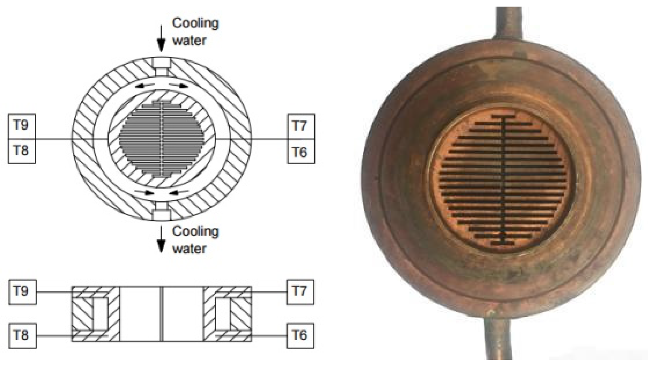
Figure 2 shows the illustration and photo of a typical parallel-plate heat exchanger (Case A1).
Due to the heat leakage to the surroundings, the coefficient
ξ is introduced into the calculation of the heat transfer rate
Qh of the gas side in the flow channel. The coefficient
ξ is defined as the ratio of the actual heat transfer rate
Qh and the cooling water heat transfer rate
Qc.
Qc can be calculated as:
where
qv is the cooling water flow rate, and ρ
water and
cwater are the density and heat capacity of water, respectively.
t1 and
t2 are the inlet and outlet temperatures of the cooling water, respectively. Because of the use of the same thermal insulation method as in Ref. [
15], the expression of coefficient
ξ is taken as:
where
th is the average temperature of the cooling water.
4. Results and Discussion
Firstly, in order to producea quick sketch of self-consistency and the impact trends of parameters, the analysis of variance is carried out to show the normal distribution plot of the residuals of 18 typical tested points (shown in
Figure 3), which indicates self-consistency of the results. In
Figure 3, the data show the normal probability distribution of residuals after an analysis of variance (ANOVA) of the tested results. The horizontal axis stands for the internally studentized residual, which is the quotient resulting from the division of a residual by an estimate of its standard deviation. The vertical axis stands for its corresponding normal possibility, which has exponential coordinates, hence, the normal distribution plot of residuals can show its self-consistency if the data lie in a neat straight line. The maximum deviation is below 10% with the correlation fitting based on RSM. The three-dimensional response surface is plotted into a polynomial correlation, with the highest order of two.
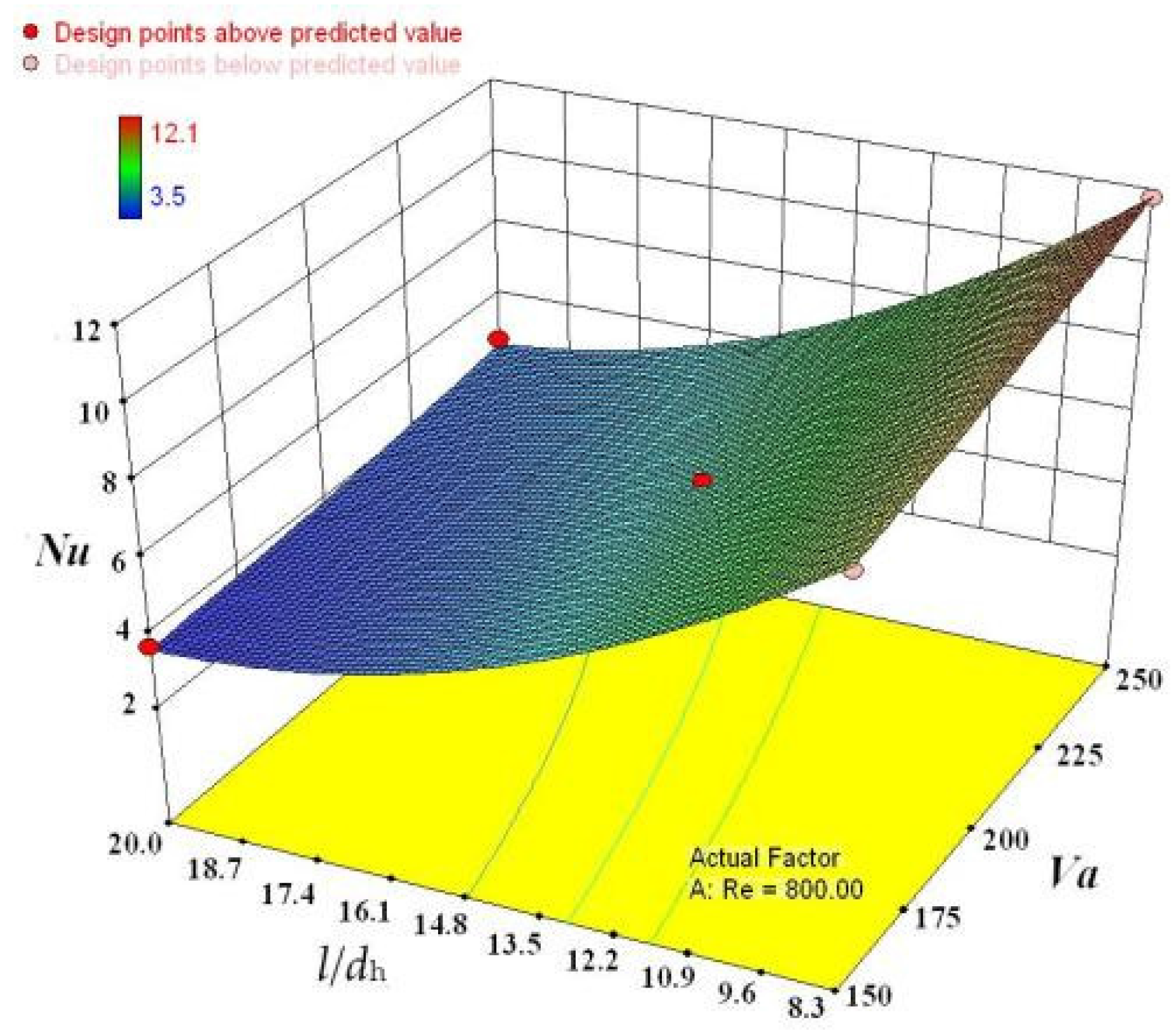
Figure 4 shows the response surface plot with a fixed maximum Reynolds number of 800 for demonstration.
From the response surfaces with fixed various parameters, it is noted that l/dh, as a geometrical parameter, has a negative influence on the Nusselt number. The rise of l/dh leads to a dramatic weakening in the heat transfer performance. Along with the fact that the maximum Reynolds number and Valensi number both have a positive impact on the Nusselt number, more detailed experimental results are obtained with error bars indicating the uncertainty of acquired data, which is not higher than 5.8%.
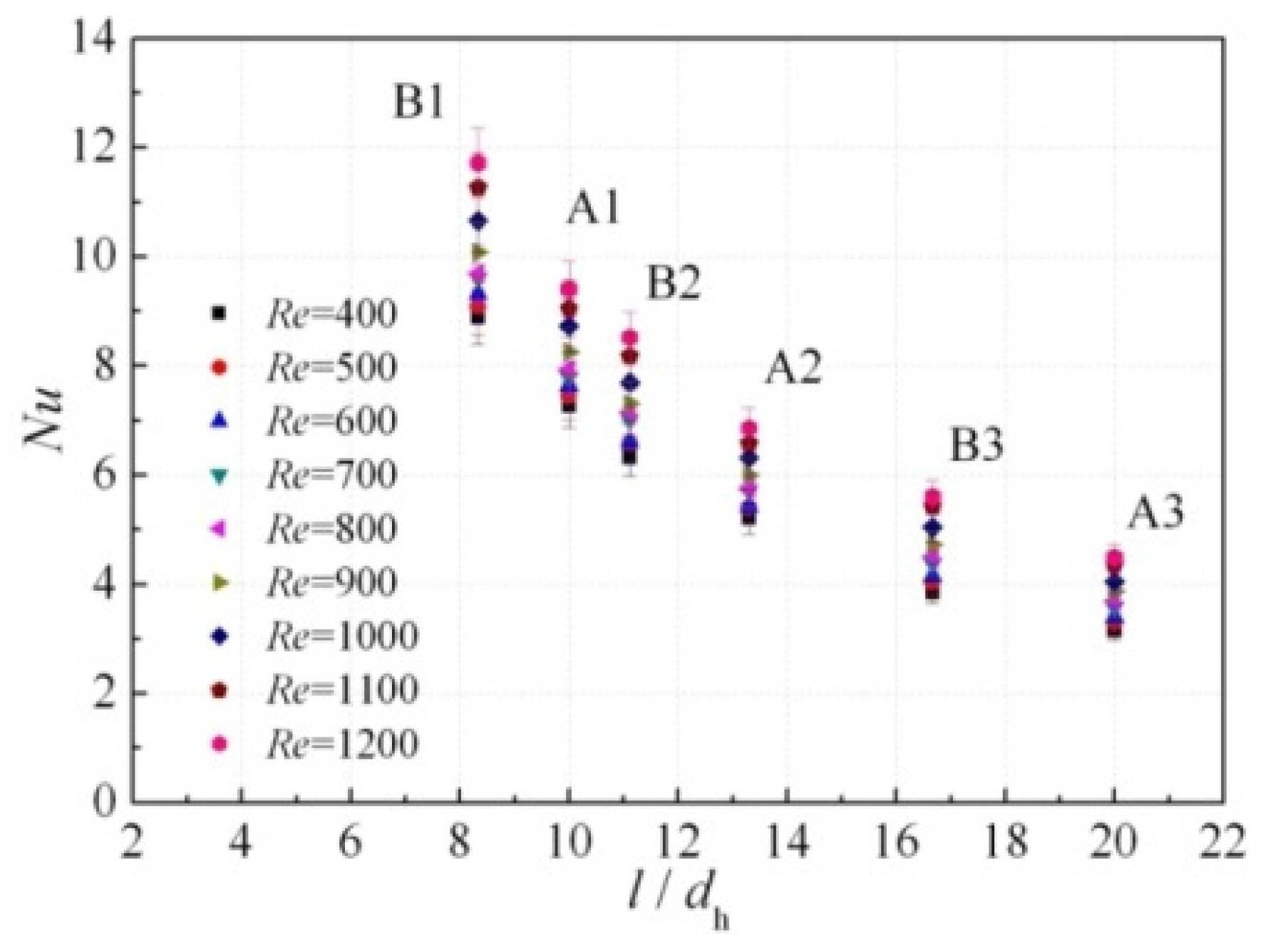
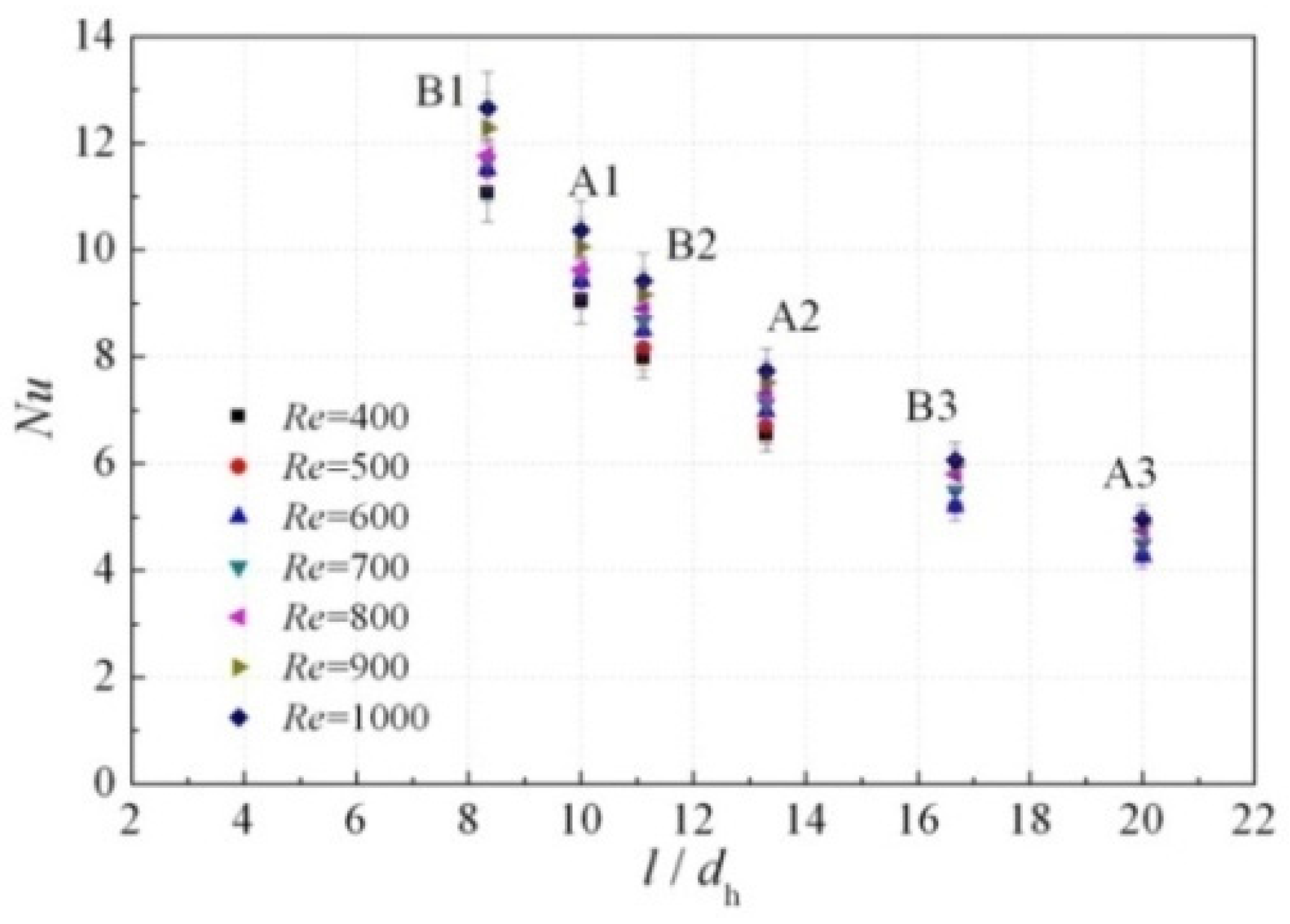
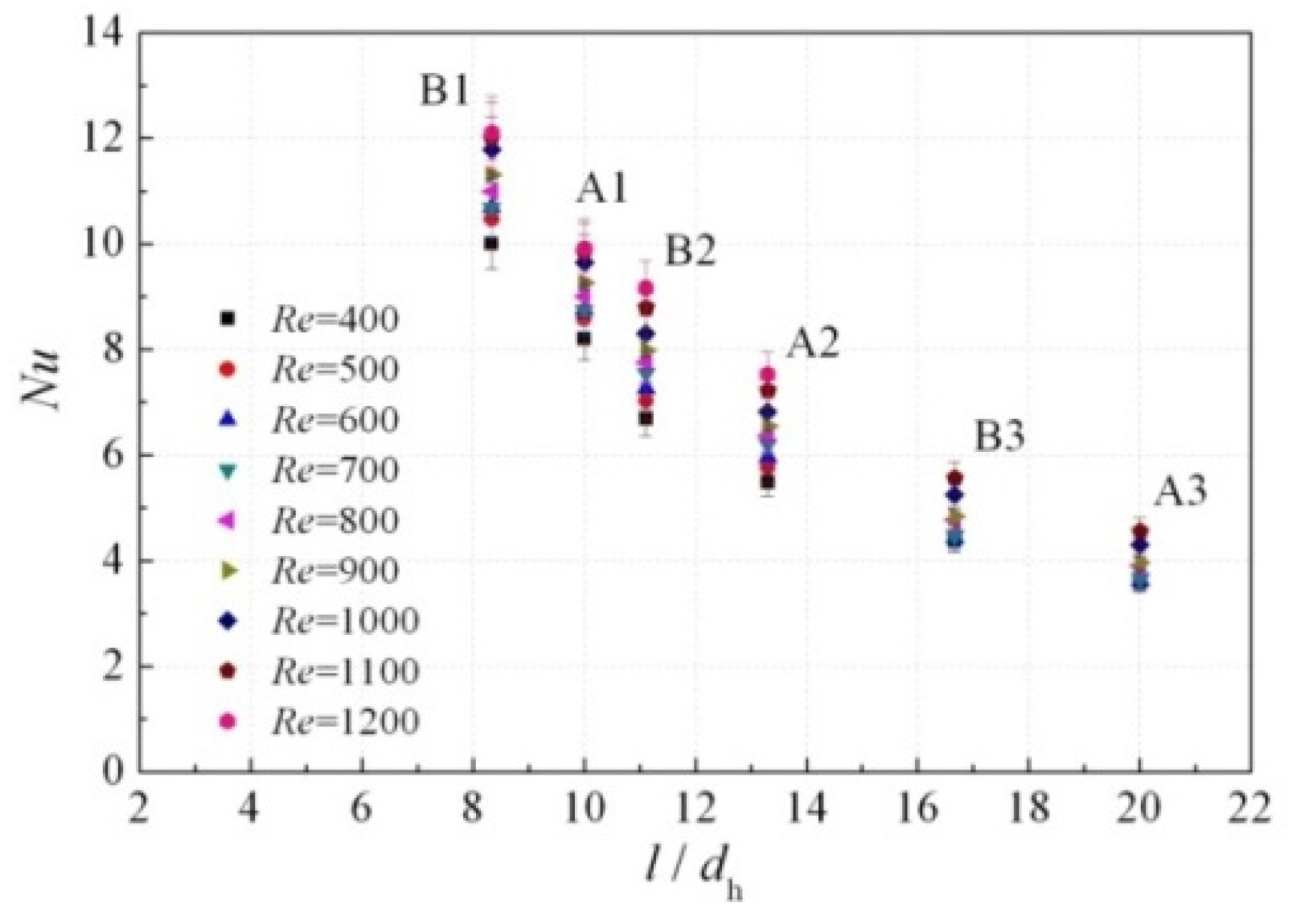
Figure 5,
Figure 6 and
Figure 7 present the Nusselt number variations with six different
l/
dh values when the Valensi numbers are 150, 200, and 250, respectively. These values are realized by the combination of three different lengths and two different hydraulic diameters, as listed in
Table 1. It can be seen from the figures that, when the Reynolds number and Valensi number are both a controlled constant, the Nusselt number decreases as
l/
dh is increased, reflected in the response surface illustrated in
Figure 4. The oscillating-flow heat transfer performance will be significantly weakened when
l/
dh is increased within the range discussed.
The results indicate that when the hydraulic diameter of the channel (roughly twice of the plate spacing) is constant, for the heat transfer with a smaller length (
l/
dh is relatively small), the heat transfer performance of the parallel plates in oscillating helium flow is significantly better than that of heat exchangers with longer fins. It is assumed that the heat transfer process is enhanced by the entrance effect of oscillating flow. In addition, if the heat exchanger length is too large, being even longer than the peak-to-peak displacement of working fluid, part of the fluid particles will be trapped in the flow channel experiencing the reciprocating motion. As the “trapped” fluid has a temperature similar to that of the wall, the oscillating heat transfer will be relatively weak. From the view of the whole heat exchanger, it can be regarded that the central part of the heat transfer area doesn’t play a good role in the heat transfer process, which will lead to a lower Nusselt number of the oscillating flow inside the entire channel. With longer channels, there will be a larger area that has no effective heat transfer. Hence, for the heat exchanger types A and B, the obtained magnitudes have orders of B1 > B2 > B3 and A1 > A2 > A3. Numerical simulation by Ishikawa et al. [
21] showed that the net heat transfer rate between solid and fluid states mainly occurred on the inlet and outlet faces of the heat exchanger with parallel plates. When the fin length is increased, the heat flux on inlet and outlet faces can be positive or negative, leading to a decrease in the net heat flux. As a result, it is also possible that the heat transfer performance of the oscillating flow in the heat exchanger with a length of 15 mm, is much better than the others due to the increased heat transfer rate per unit area.
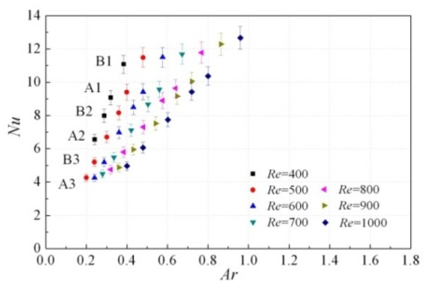
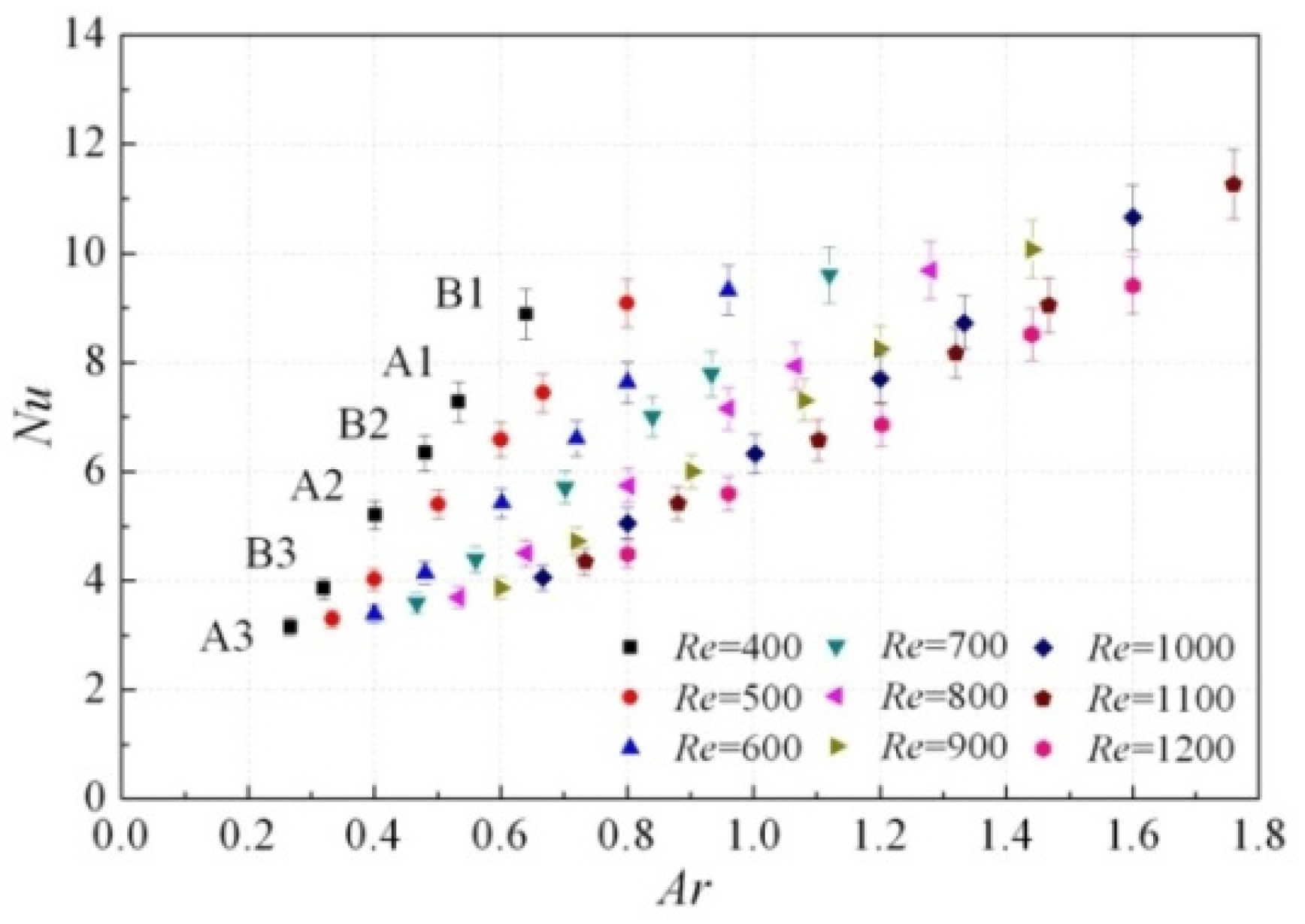
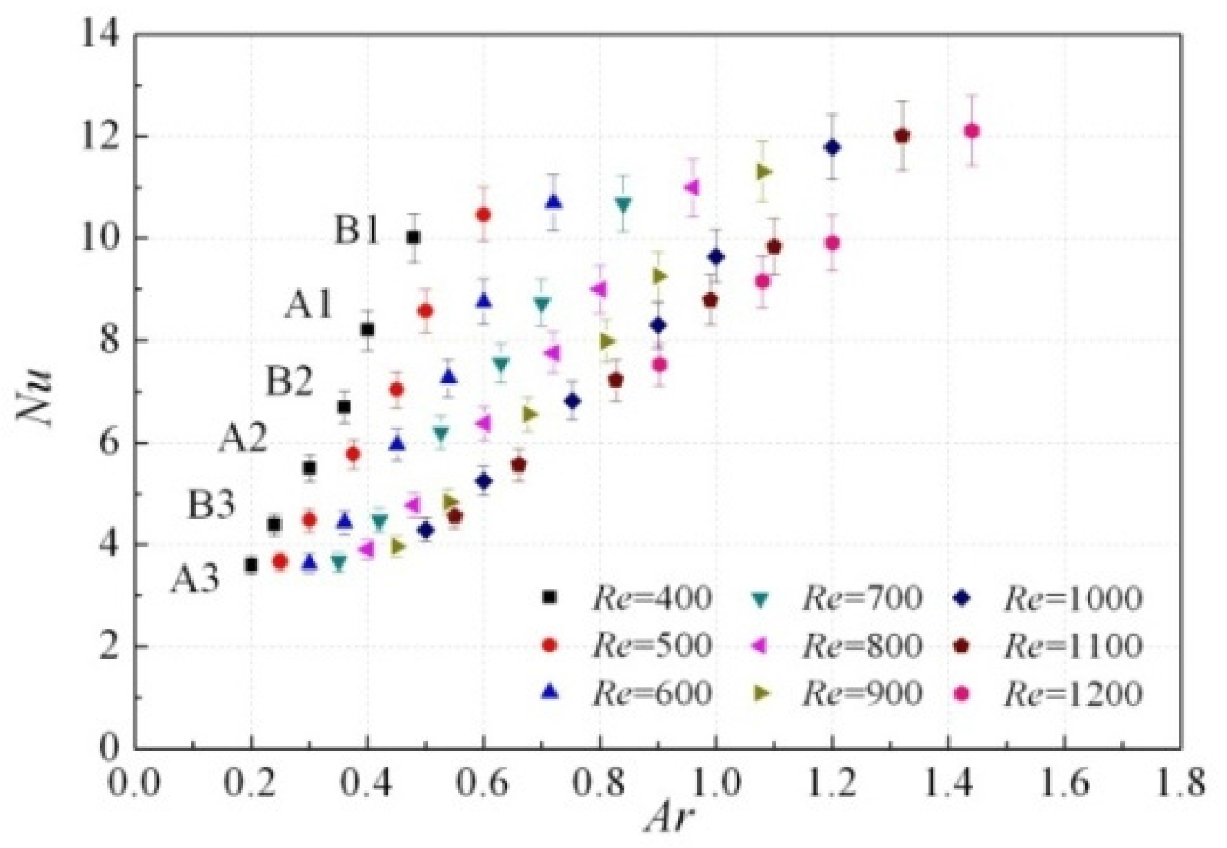
Figure 8,
Figure 9 and
Figure 10 present the Nusselt number variations of
Ar when Valensi numbers are 150, 200, and 250, respectively. These figures also show that for heat exchangers with the same hydraulic diameter, but different length, the Nusselt number decreases as the heat exchanger length is increased. It can be seen that when
Re and
Va are controlled, heat exchangers with a length of 20 mm (A2 and B2) have about a 30% lower
Nu number than those with a length of 15 mm (A1 and B1), and heat exchangers with a length of 30 mm (A3 and B3) have about a 50% lower
Nu number than those with a length of 15 mm. When considering those with a length of 15 mm (A1 and B1), it is evident that better heat transfer performance mainly occurs when
Ar is larger than 1, supporting the conclusion offered by Hofler [
18] and Piccolo [
19]. In fact, when
Re and
Va are controlled constants, the relative fluid displacement amplitude
Ar is equivalent to the reciprocal of
l/
dh.
Compared to
Figure 5,
Figure 6 and
Figure 7, the
Nu variations of
Ar reflect the same physical pattern. However, the impact of relative fluid displacement amplitude is actually a result of comprehensive effects; an aspect which has been neglected in the previous study. Piccolo [
22] numerically studied the relationship between the mean convective heat transfer coefficient
h, and the relative displacement amplitude
Ar, under the same pressure ratio based on energy conservation. Results showed that remarkably,
h increased with increasing
Ar when
Ar > 1, while
h remained constant when
Ar ≤ 1, which does not reflect the results concluded in this paper. As
Ar includes the geometrical parameters, as well as the impacts of
Re and
Va, it is difficult to explain the direct relationship between the oscillating-flow heat transfer and each parameter. In comparison,
l/
dh, instead of
Ar, can be chosen as an important geometrical parameter, which should be taken into account when considering the empirical correlation for the finned heat exchangers with parallel plates, working under oscillating conditions.
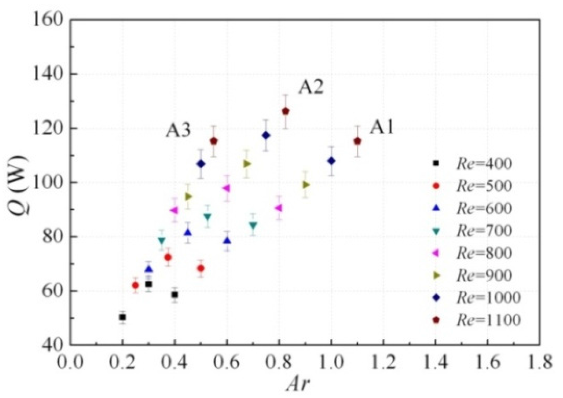
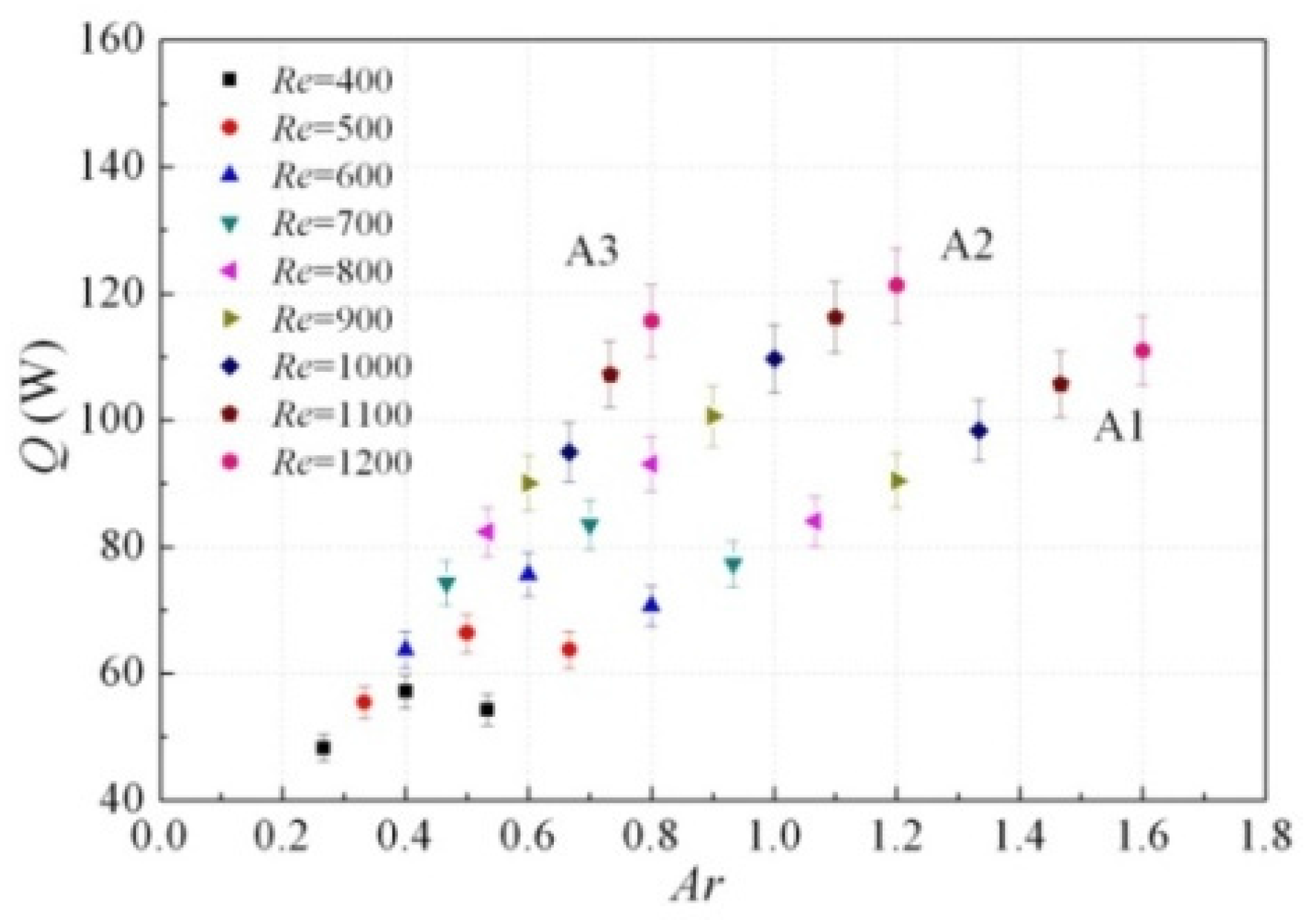
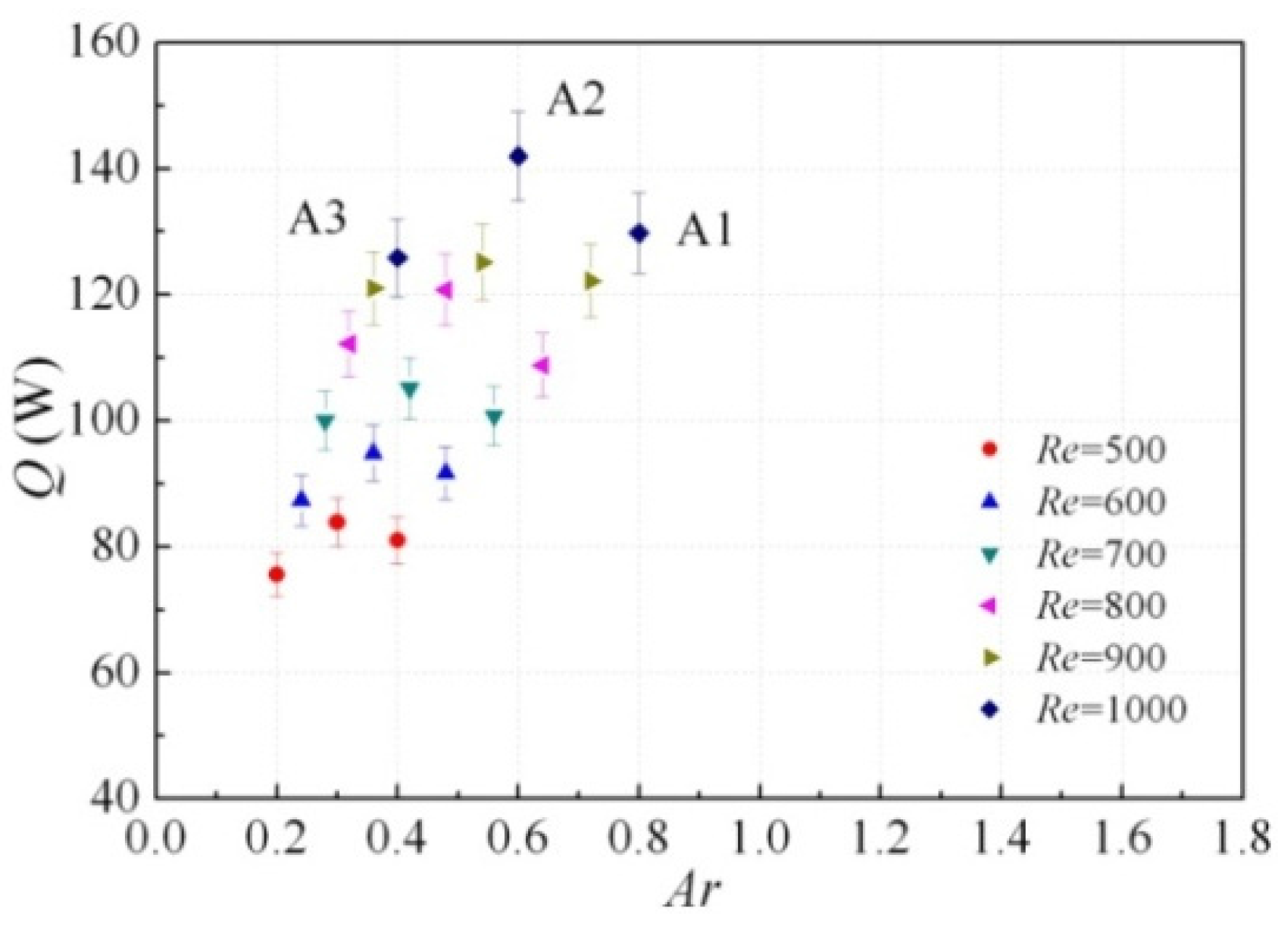
Figure 11,
Figure 12 and
Figure 13 present the actual heat transfer rate variations of
Ar when the Valensi numbers are 150, 200, and 250, respectively. The results show that, for the same type of heat exchanger with the same hydraulic diameter, there exists an optimal fin length for achieving the required heat load. Out of the three lengths tested, the length of 20 mm achieves the largest heat transfer rate for each working condition. In the practical design of regenerative thermal systems, the fin efficiency and the effective heat transfer area should be considered, as well as the space-cycle average Nusselt number.
In order that the experimental data can be conveniently applied to the design of finned heat exchangers working under oscillating conditions in regenerative thermal engines, further data fitting was implemented to obtain a relatively comprehensive empirical correlation. The Reynolds number, Valensi number, Mach number, Prandtl number, specific heat ratio, ratio of length and hydraulic diameter, and pressure ratio
PR, are considered as the main similarity criterions relating to the oscillating-flow heat transfer in heat exchanging channels [
5]. This experiment adopted helium gas as the working fluid, so the specific heat ratio and Prandtl number can be considered as nearly constant. In addition, the Mach number implies the compressibility of fluid, which was kept at a value much lower than one in the experiment. Finally, based on the discussion above, the expression of the empirical correlation is defined as:
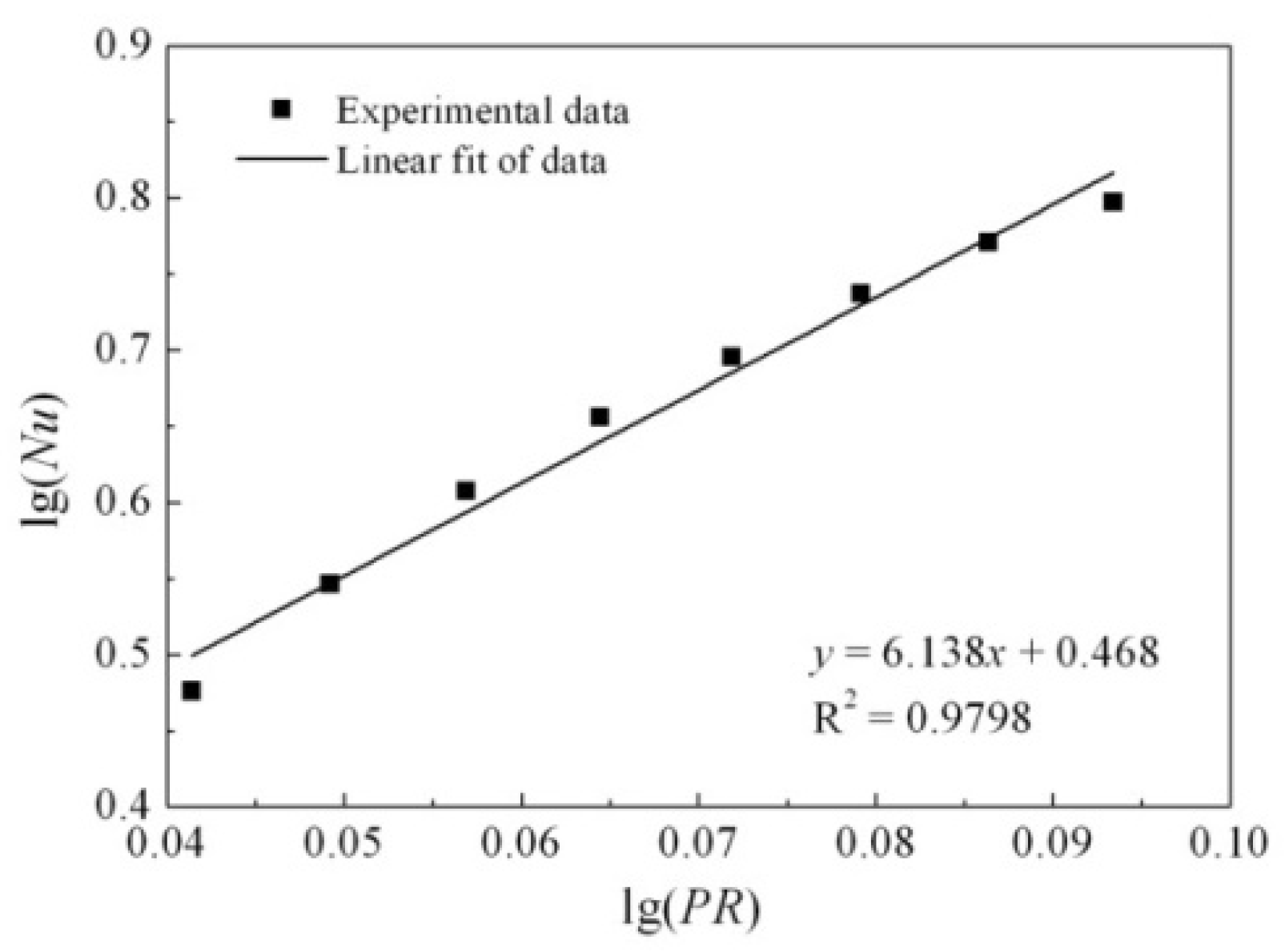
It is ascertained that
b = 6.138 from the linear fitting of log(
Nu) and log(
PR) with a coefficient determination of
R2 = 0.9798, as shown in
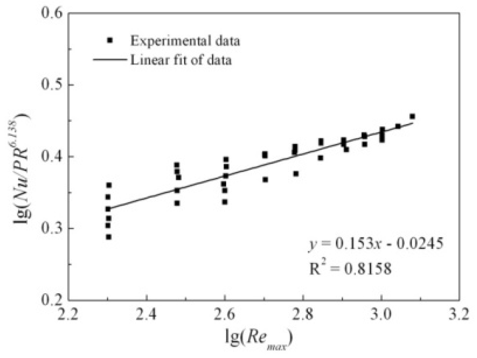
Figure 14. Following this, log(
Nu/
PR6.138) and log(
Remax) are linearly fitted with a slope of
m = 0.153 and a coefficient determination of
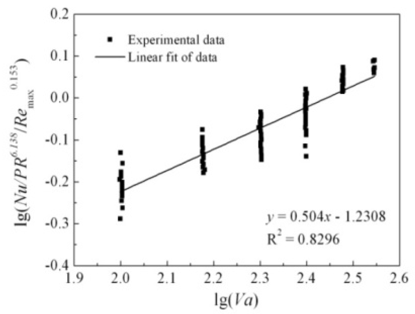
R2 = 0.8158. Next, by completing log(
Nu/
PR6.138/
Remax0.153) and log(
Va) linear fitting with
n = 0.504 and
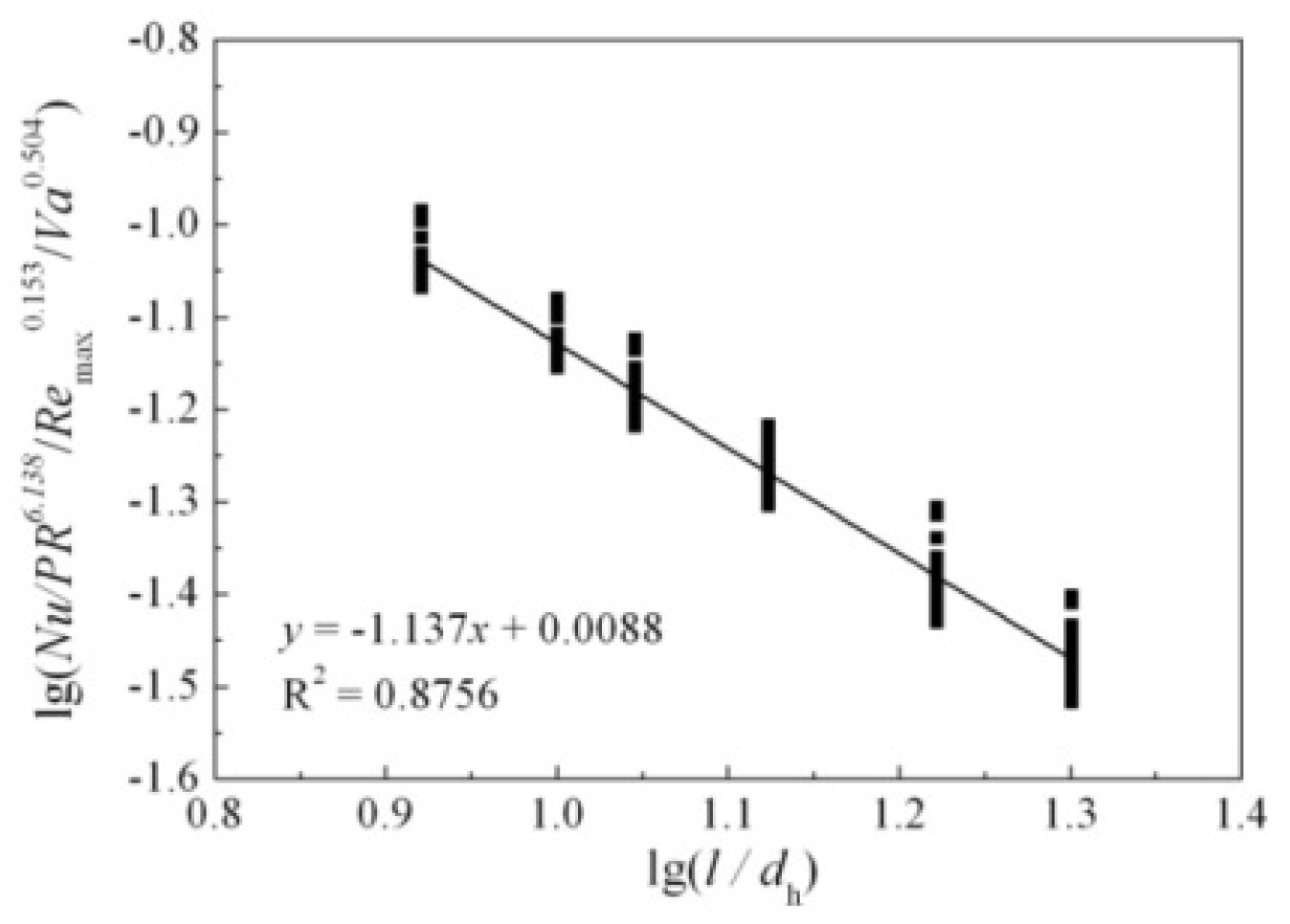
R2 = 0.8296, the coefficient
c is determined as −1.137 and
a is calculated from the intercept, producing a value of 1.021.
Figure 14,
Figure 15,
Figure 16 and
Figure 17 show the determination of all the coefficients.
As a result, within the ranges used in the experiments, i.e., 200 <
Remax < 1200, 100 <
Va < 350, 1.1 <
PR < 1.3, and 8.3 <
l/
dh < 20, the space-cycle average Nusselt number of oscillating-flow heat transfer in the finned heat exchanger with parallel plates, can be predicted using the following correlation:
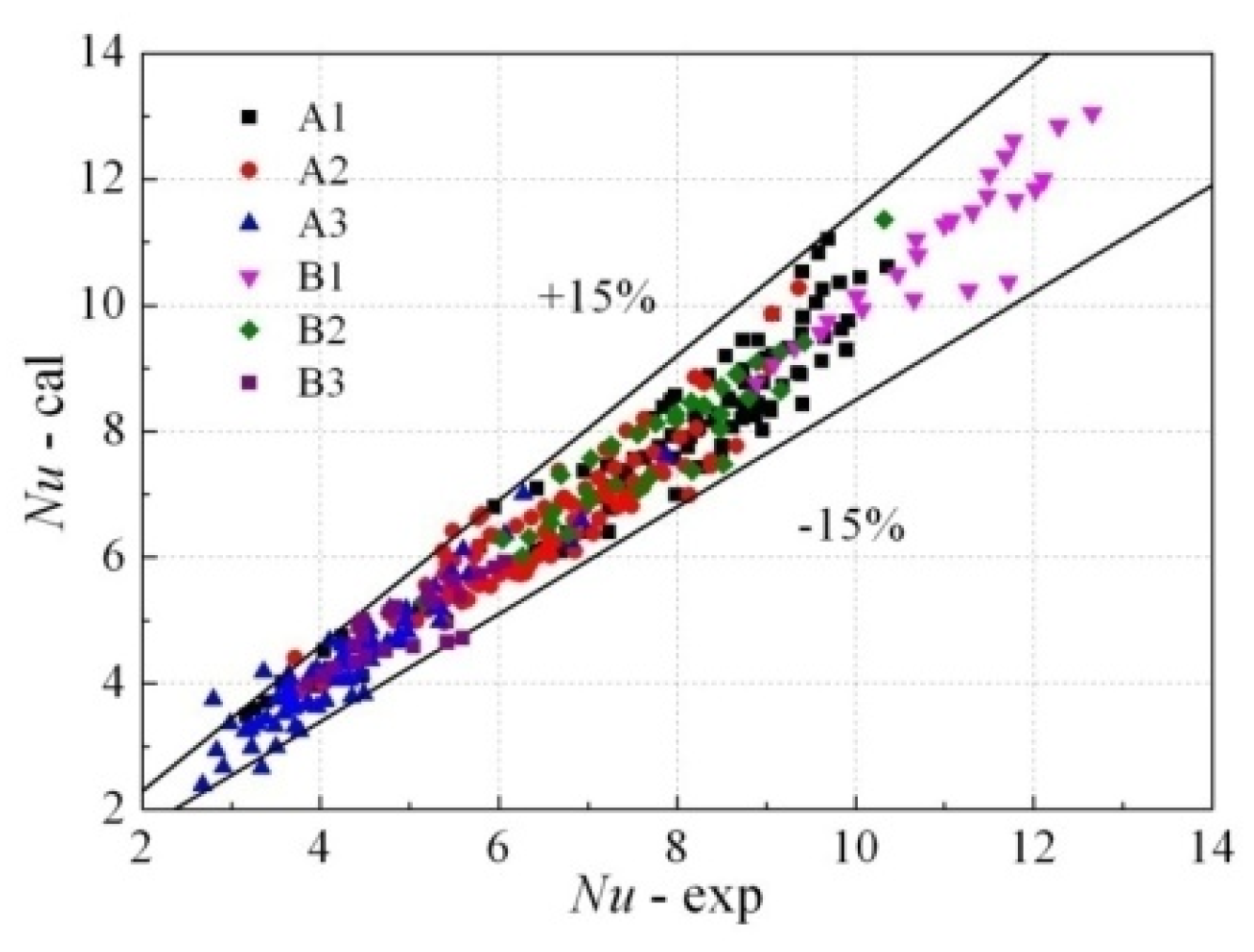
To prove the self-consistency of the empirical correlation, the predicted results are compared to the corresponding experimental results, as shown in
Figure 18. Out of the total 298 tested data points, 98.6% of the predicted points lie within adeviation of ±20%, and 83.9% of the predicted points lie within adeviation of ±10%, indicating that the comprehensive empirical correlation is able to provide acritical guidance for the design of finned heat exchangers in regenerative thermal engines.


