
Dynamic Response of a Simplified Turbine Blade Model with Under-Platform Dry Friction Dampers Considering Normal Load Variation


Abstract
:
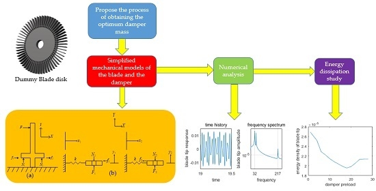
1. Introduction
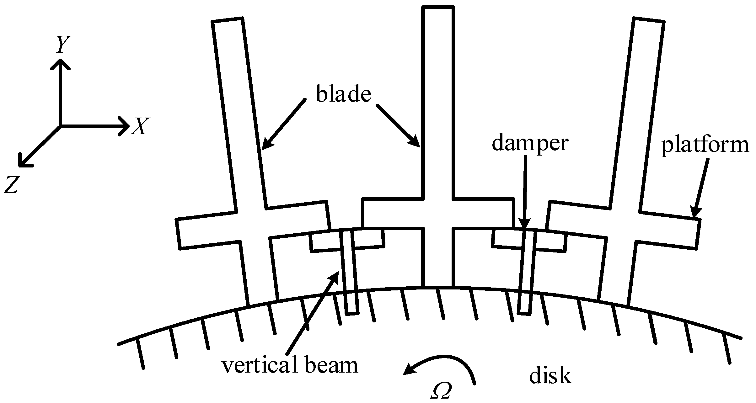
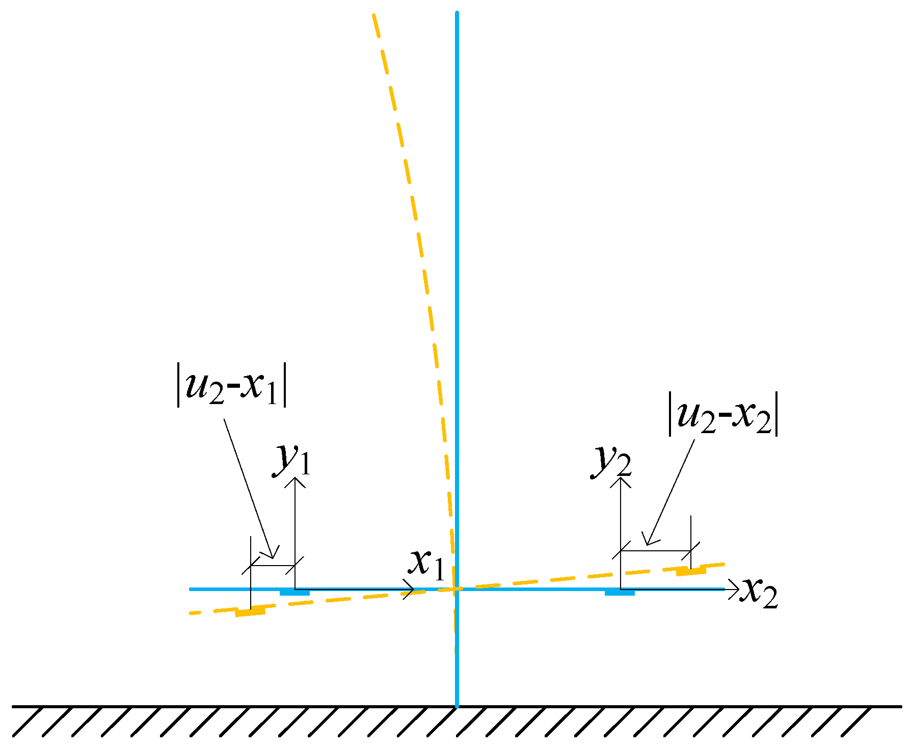
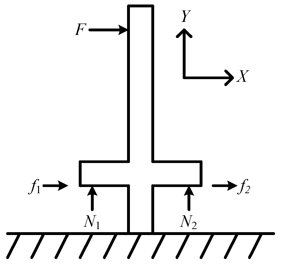
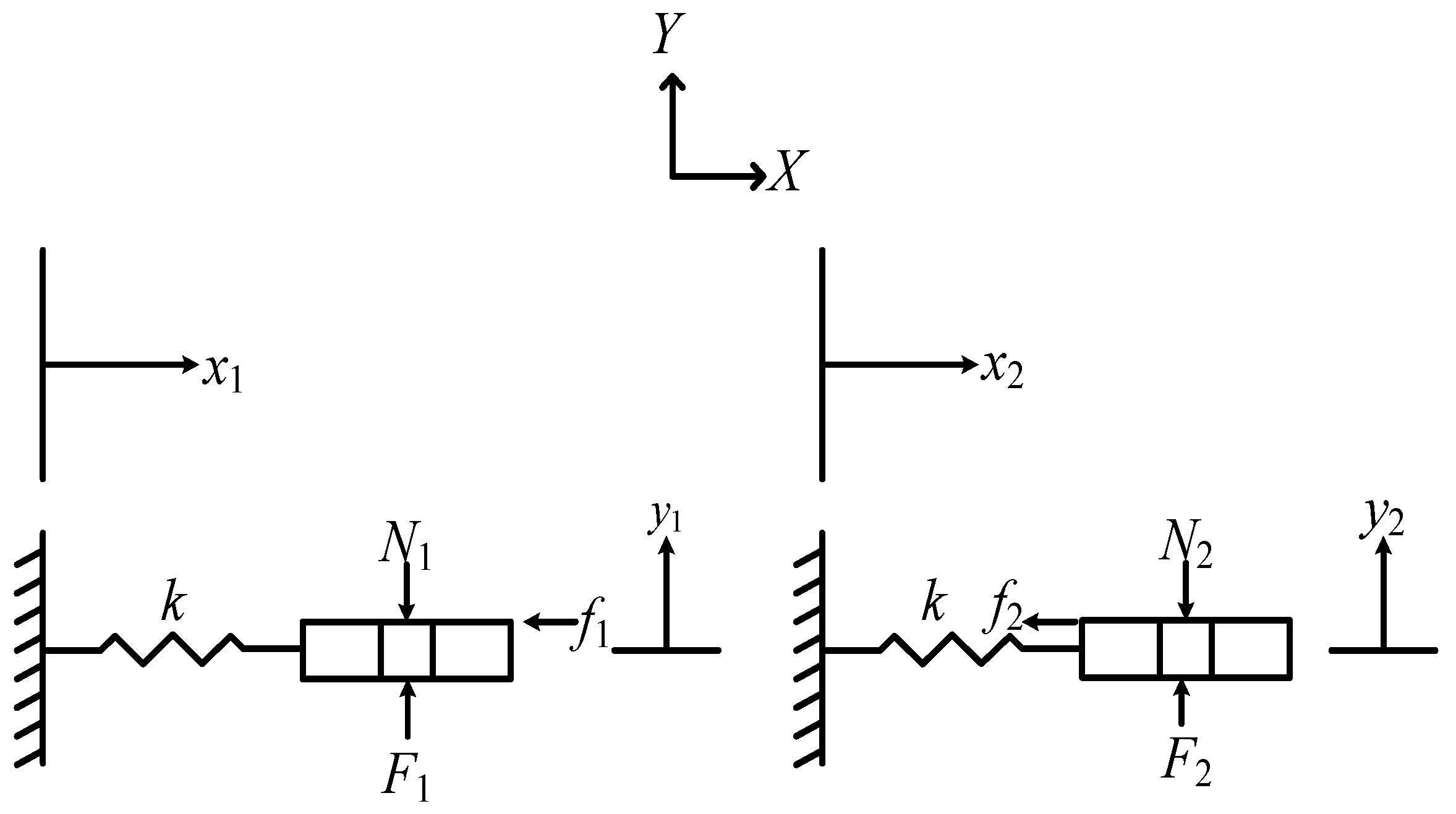
2. Blade-Damper Model and Theoretical Development
3. Numerical Simulation
3.1. Gross Slip Regime
3.2. Stick-Slip Regime
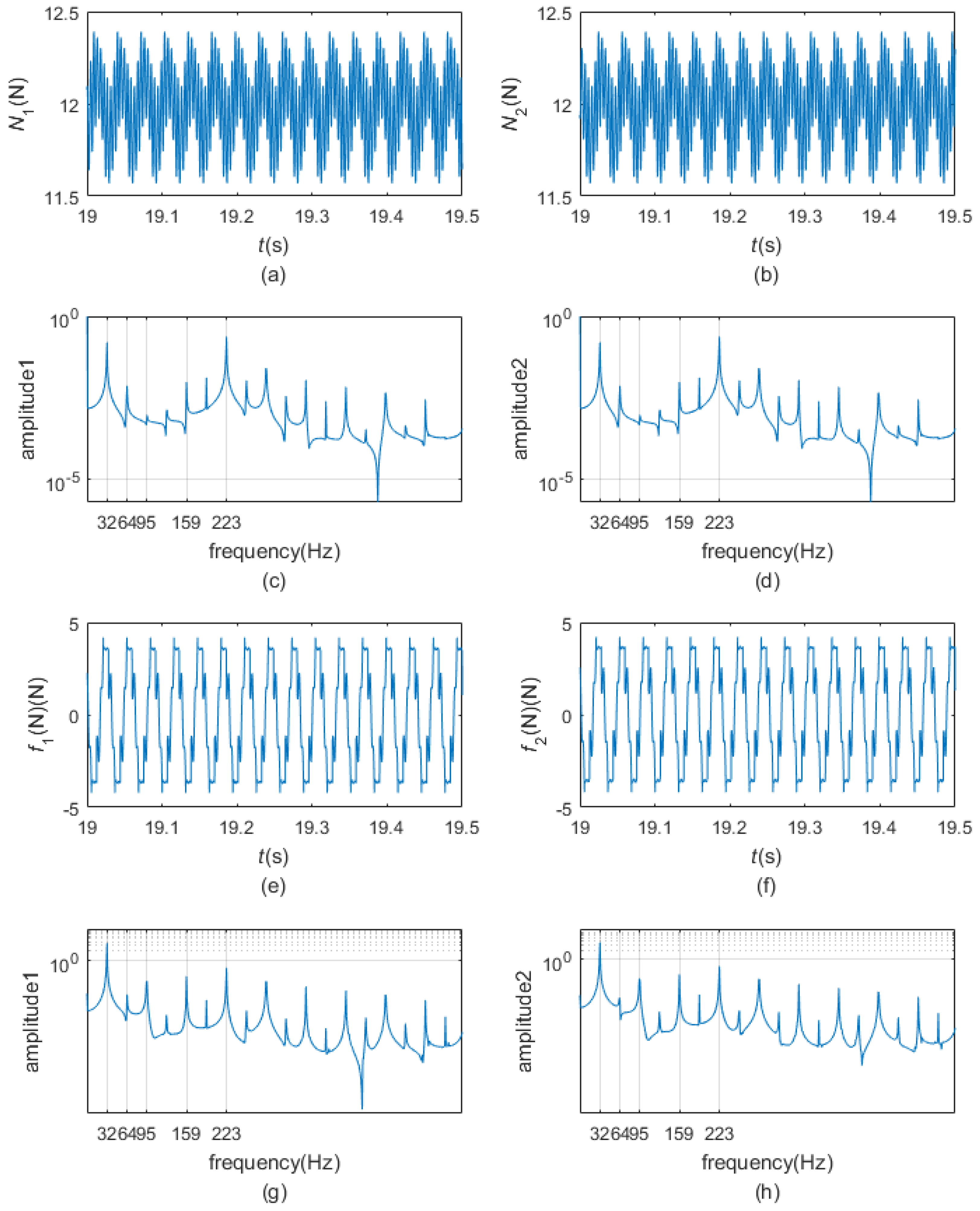
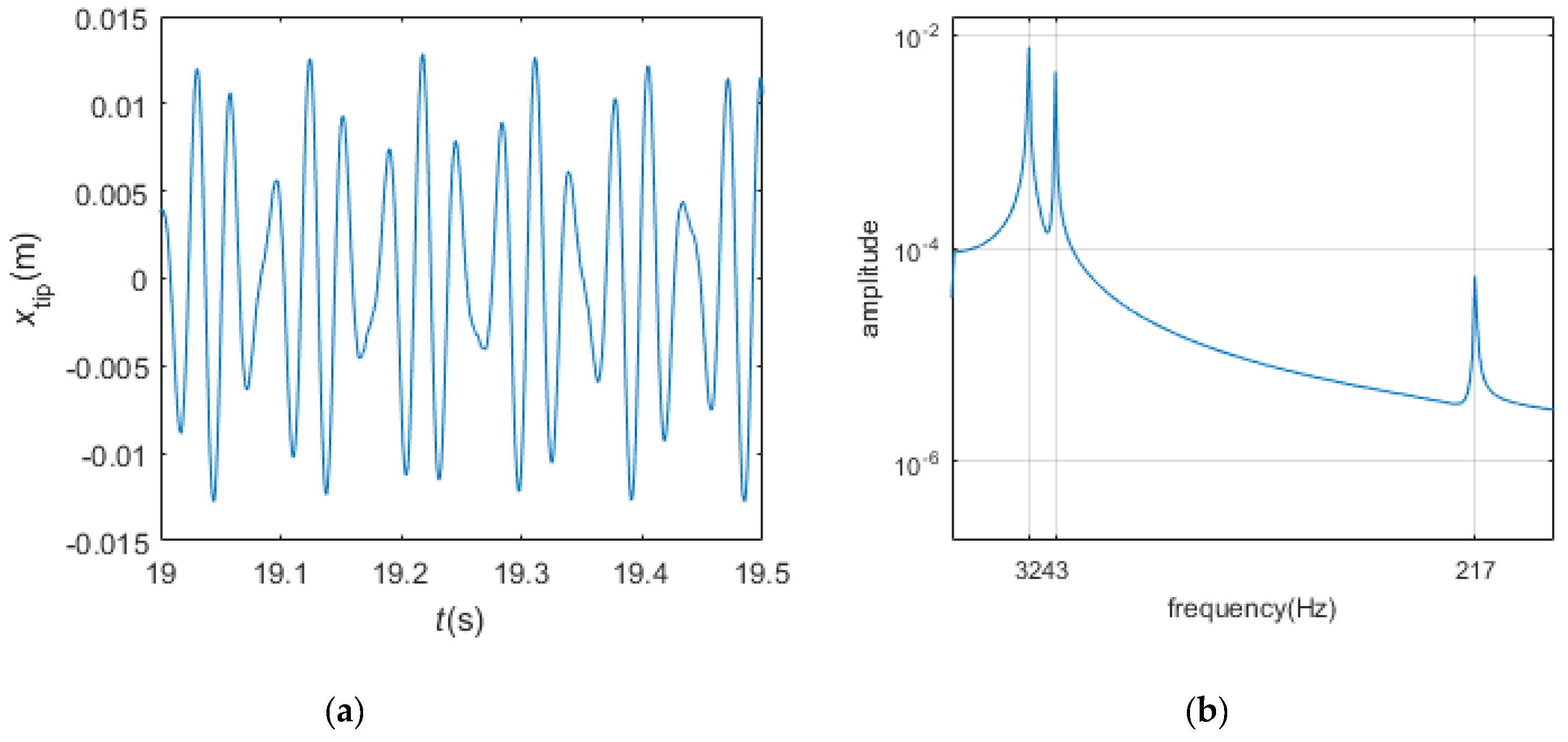
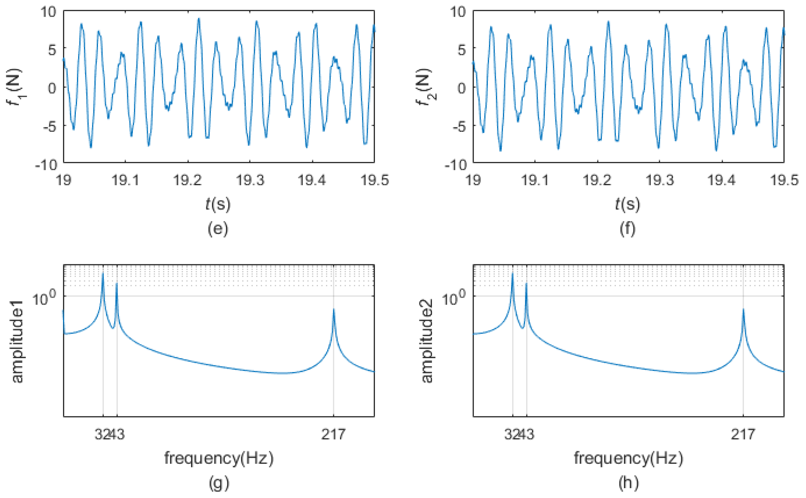
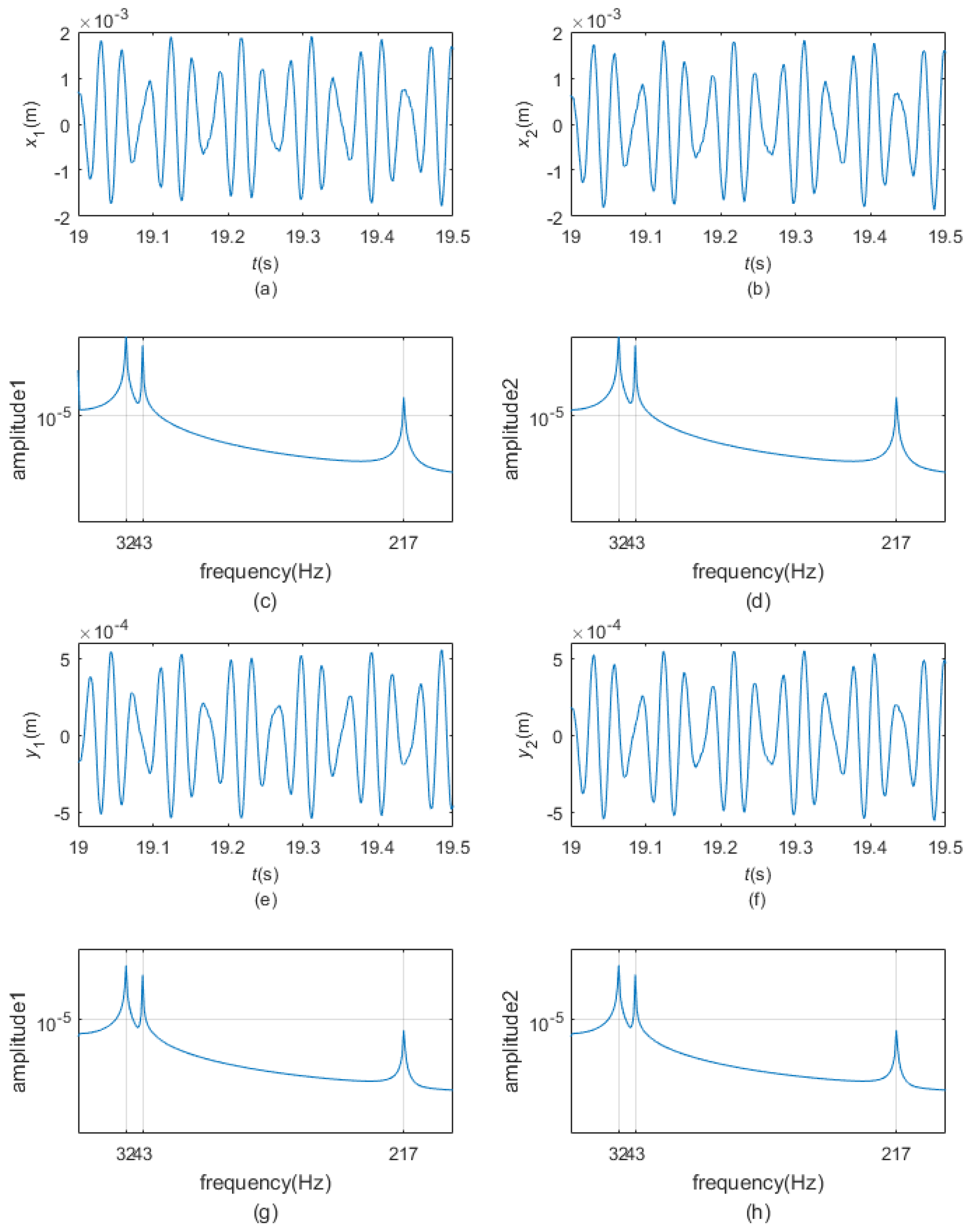
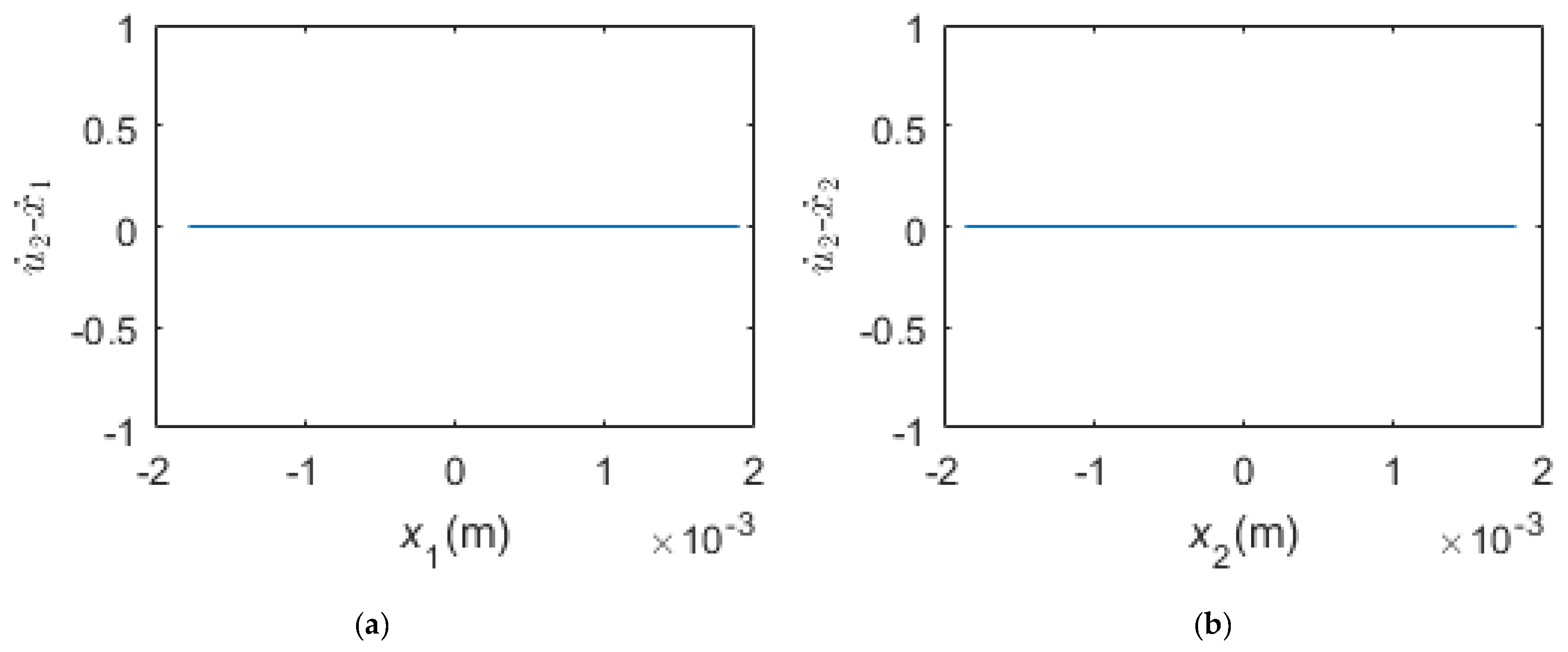
3.3. Complete Stick Regime
3.4. The Effect of the Preload for Vibration Reduction
3.5. Further Discussion
4. Conclusions
- (1)
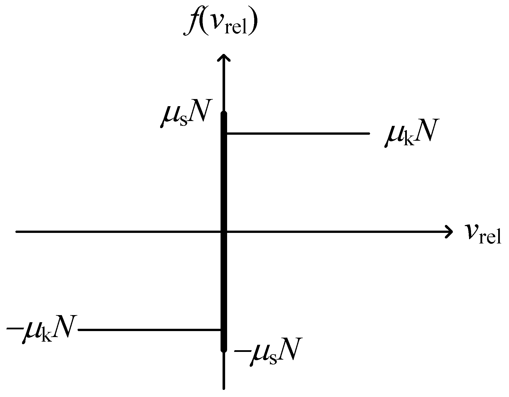
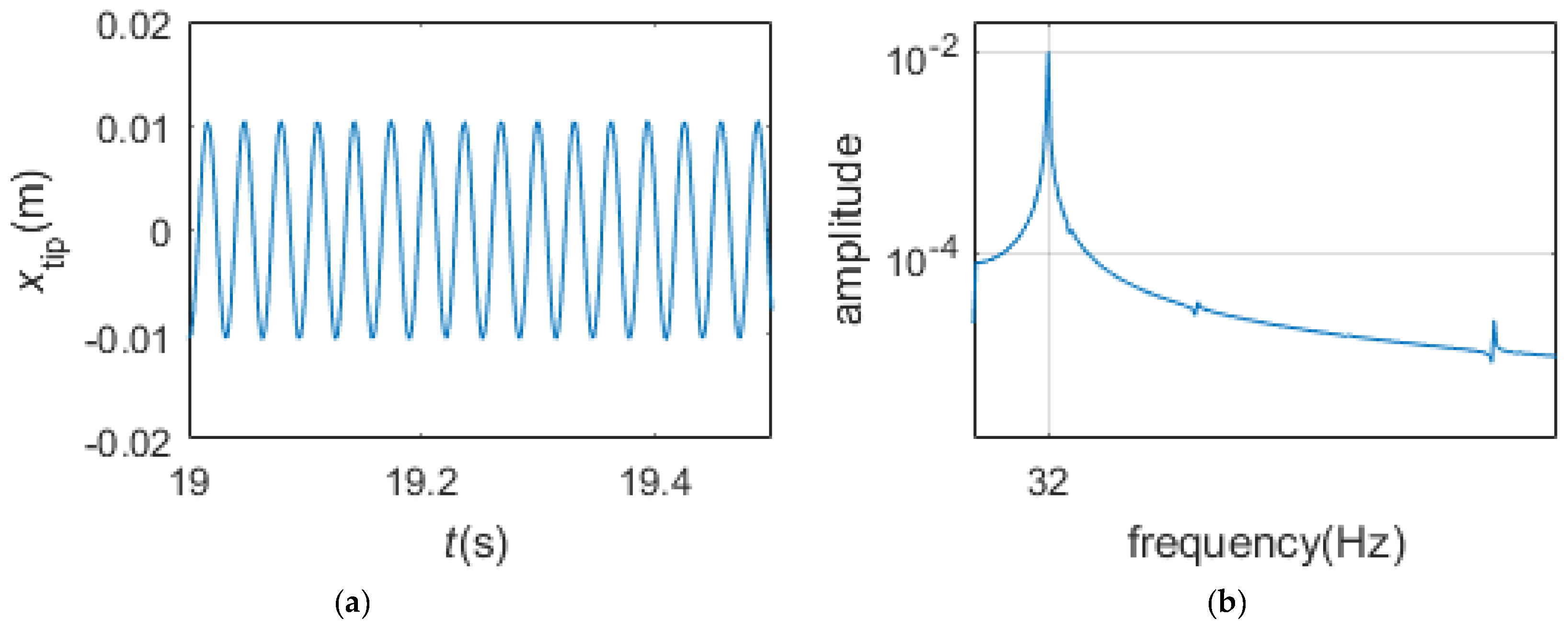
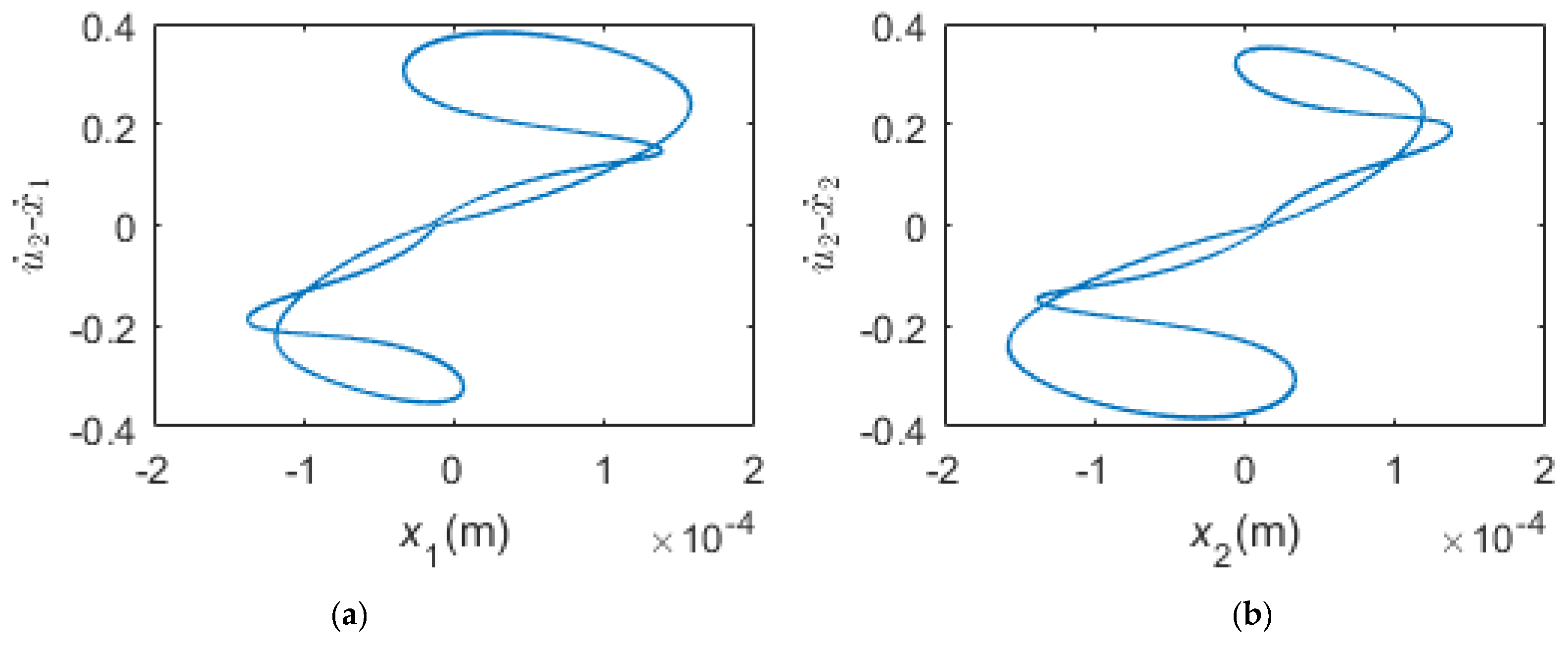
- When the pre-load is very small, the two dampers are all in gross slip regime in the steady state. The motion of the blade tip is harmonic. The normal contact forces fluctuate around the preload and are periodic, the friction forces and undulate between and , respectively, and are also periodic. The motions of the two dampers are not harmonic but periodic whose periods are the period of the excitation. The phase plane maps of the dampers are smooth closed curves.
- (2)
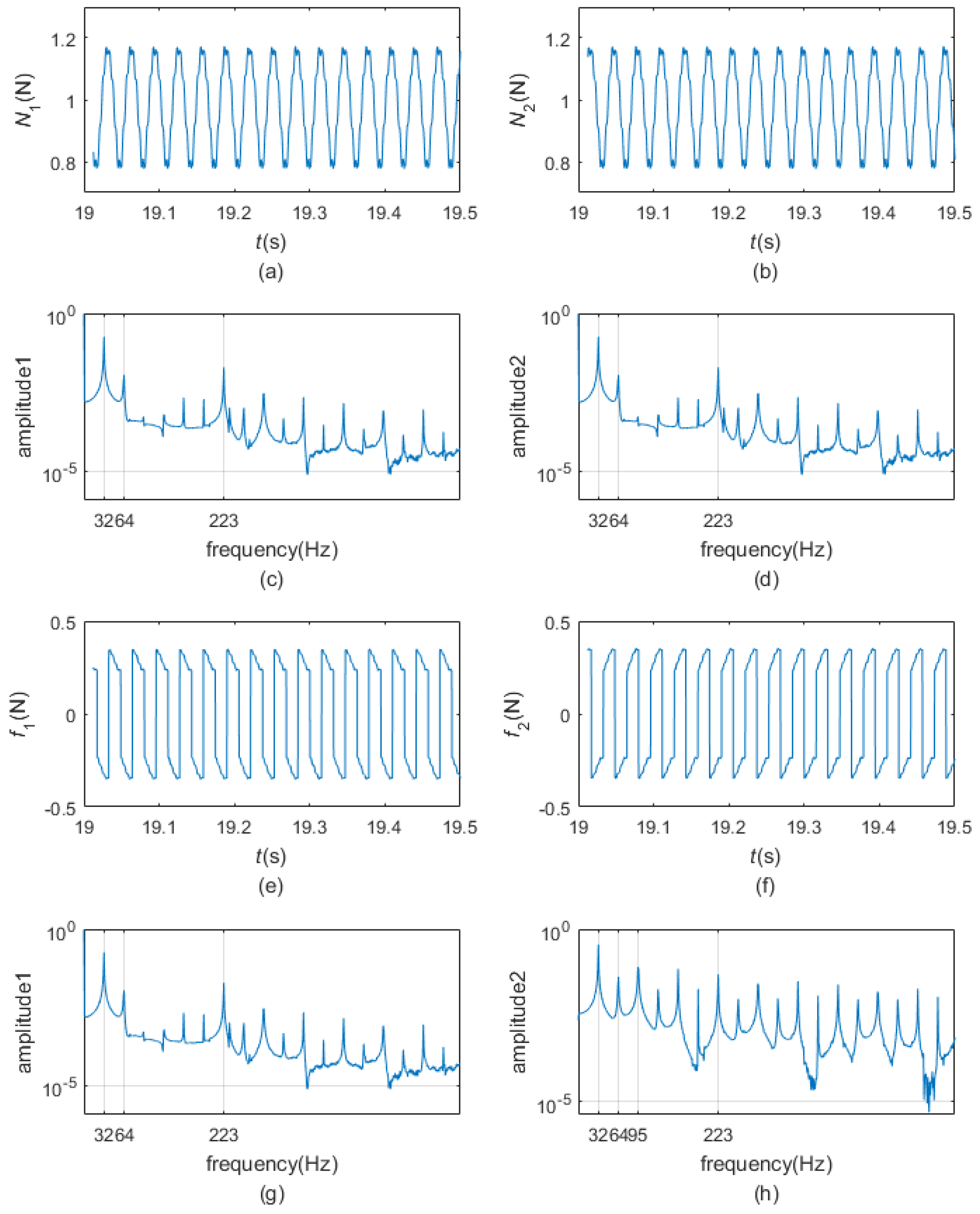
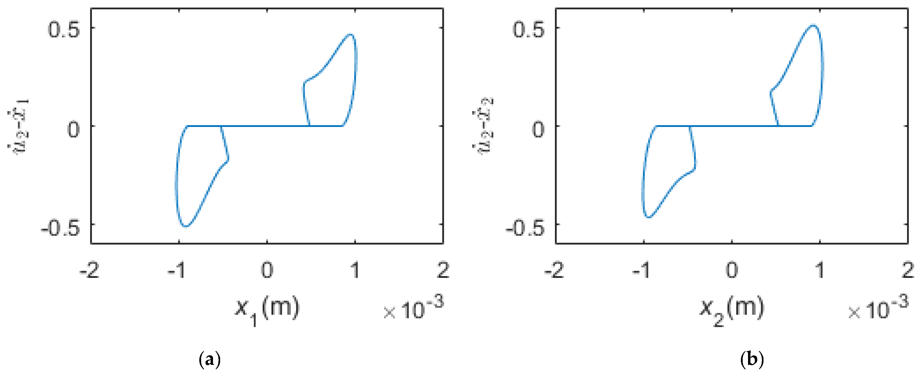
- When the pre-load is bigger and appropriate, the two dampers could undergo stick-slip vibration in the steady state. The motion of the blade tip is periodic rather than harmonic. The normal contact forces continue to fluctuate around the preload and are periodic as in gross slip regime. Friction forces and fluctuate between and , respectively, and are periodic. At times, equals and equals ; at any other time, friction forces and could reach and , separately. The motions of the dampers are similar to those in the gross slip regime. The phase plane maps of the dampers are closed curves but not smooth.
- (3)
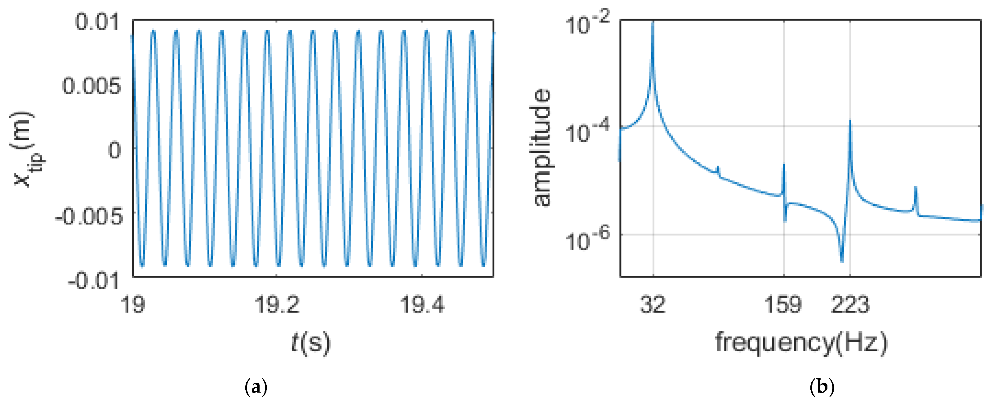
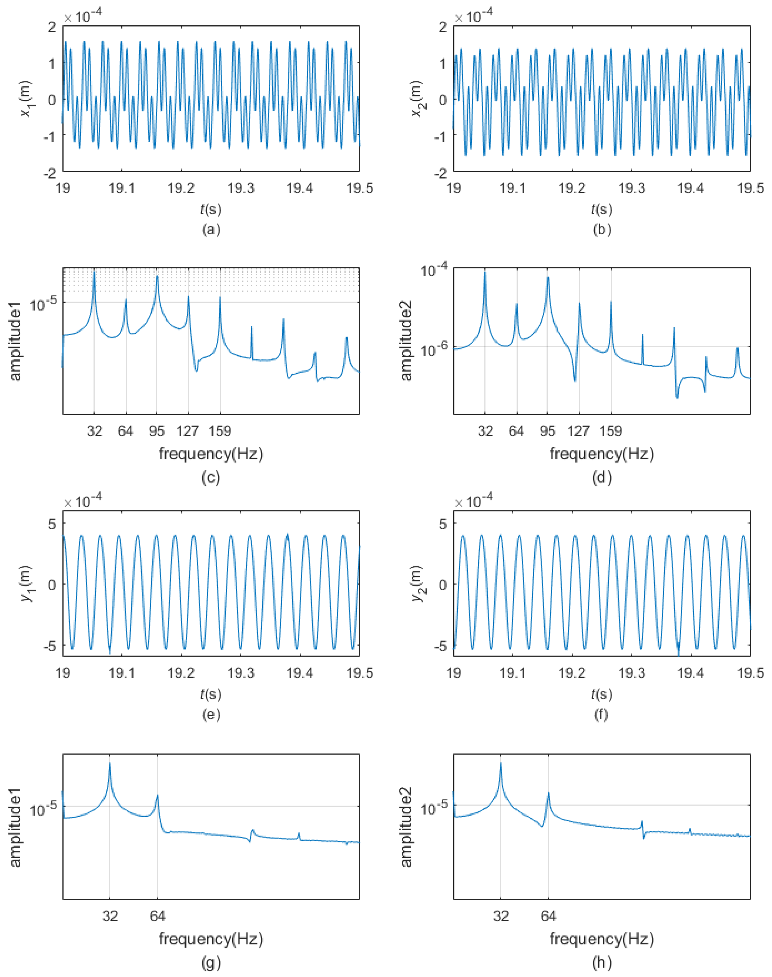
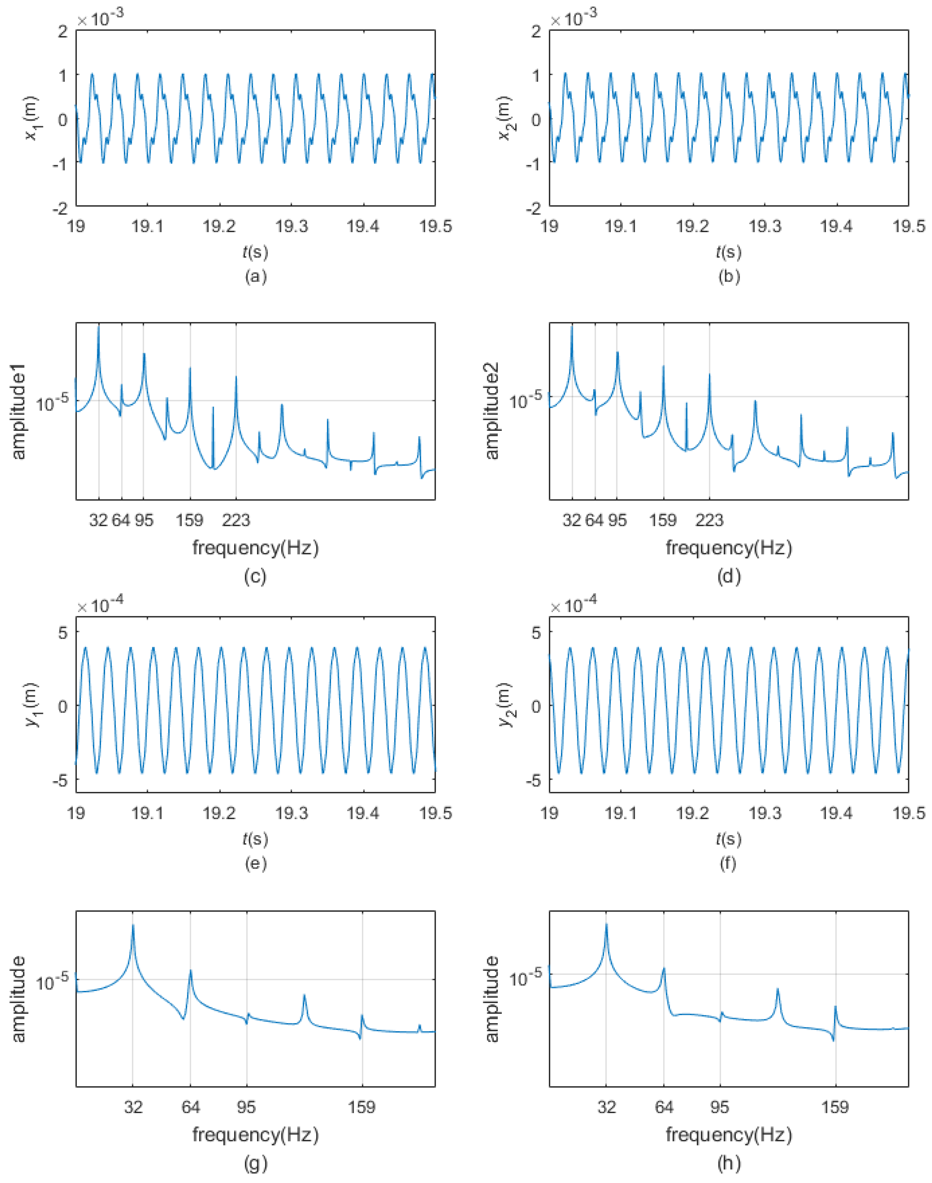
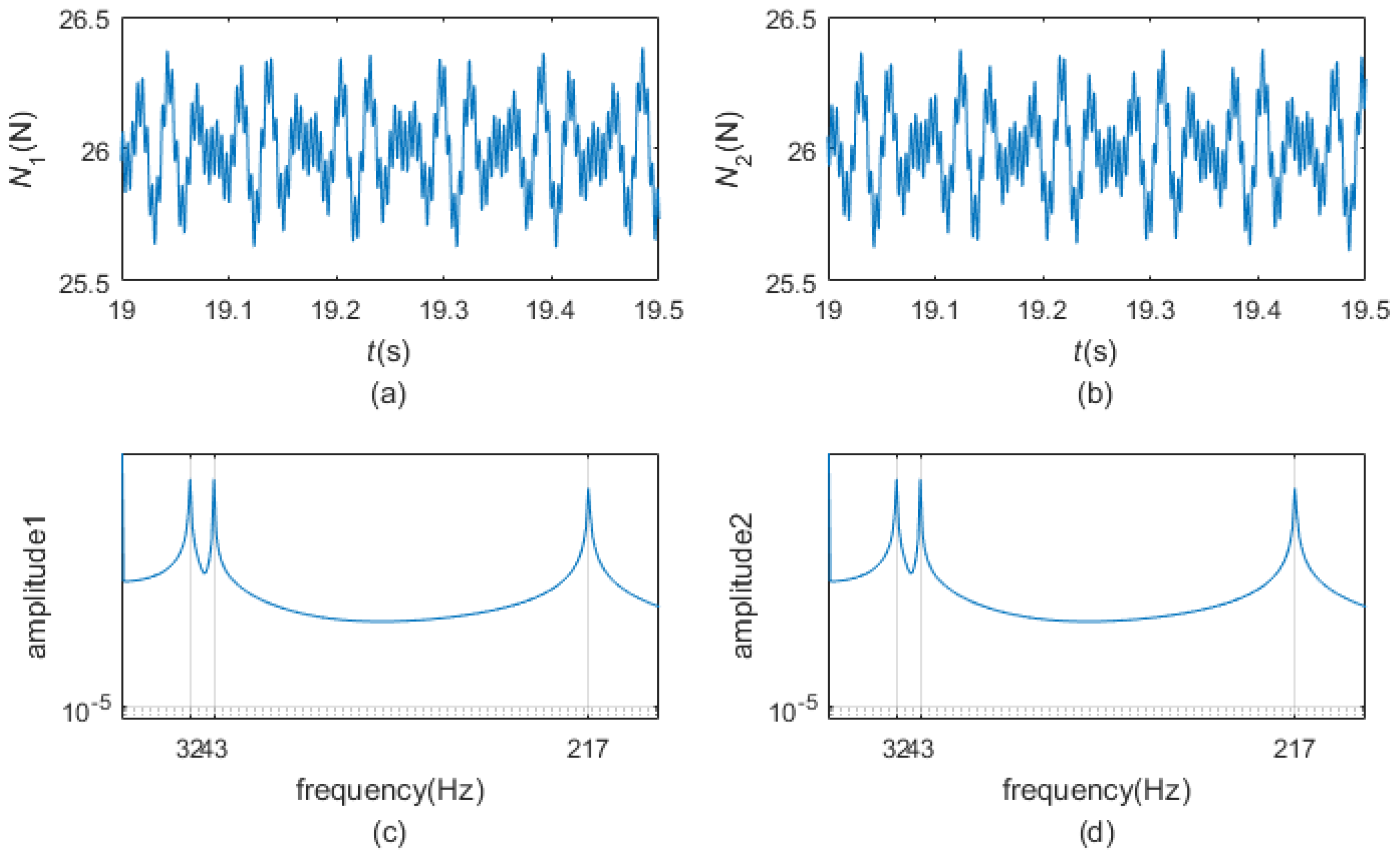
- When the pre-load is high enough, the two dampers are all in pure stick regime in the steady state. During pure stick scheme, the blade-platform structure and the dampers form one new system. The normal contact forces and the friction forces display a quasi-periodic variation, and the motion of the blade tip changes to quasi-periodic vibration as well. The motions of the dampers are non-periodic but quasi-periodic. There are three peaks in the frequency spectrum plots: the frequency of the first peak is the same as the excitation frequency, but the frequencies of the second peak and the third peak are now the first-order bending frequency and the fifth-order bending frequency of the whole new system.
- (4)
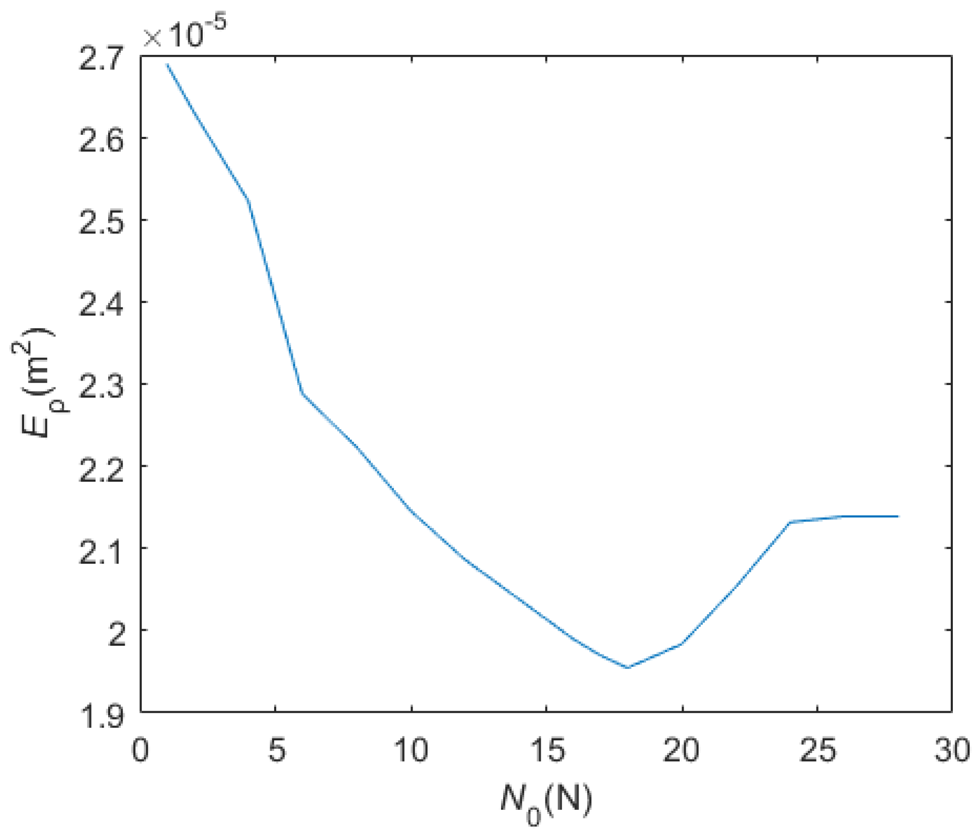
- There is an optimal pre-load which can make the biggest vibration reduction.
Acknowledgments
Author Contributions
Conflicts of Interest
References
- Xie, Y.; Meng, Q. Numerical model for steam turbine blade fatigue life. J. Xi’an Jiaotong Univ. 2002, 36, 912–915. [Google Scholar]
- Griffin, J. Friction damping of resonant stresses in gas turbine engine airfoils. J. Eng. Gas Turbines Power 1980, 102, 329–333. [Google Scholar] [CrossRef]
- Menq, C.-H.; Bielak, J.; Griffin, J. The influence of microslip on vibratory response, part I: A new microslip model. J. Sound Vib. 1986, 107, 279–293. [Google Scholar] [CrossRef]
- Csaba, G. Microslip Friction Damping: With Special Reference to Turbine Blade Vibrations; Linköping University: Linköping, Sweden, 1995. [Google Scholar]
- Sanliturk, K.; Ewins, D. Modelling two-dimensional friction contact and its application using harmonic balance method. J. Sound Vib. 1996, 193, 511–523. [Google Scholar] [CrossRef]
- Xia, F. Modelling of a two-dimensional Coulomb friction oscillator. J. Sound Vib. 2003, 265, 1063–1074. [Google Scholar] [CrossRef]
- Yang, B.; Chu, M.; Menq, C. Stick–slip–separation analysis and non-linear stiffness and damping characterization of friction contacts having variable normal load. J. Sound Vib. 1998, 210, 461–481. [Google Scholar] [CrossRef]
- Cigeroglu, E.; Lu, W.; Menq, C.-H. One-dimensional dynamic microslip friction model. J. Sound Vib. 2006, 292, 881–898. [Google Scholar] [CrossRef]
- Cigeroglu, E.; An, N.; Menq, C.-H. A microslip friction model with normal load variation induced by normal motion. Nonlinear Dyn. 2007, 50, 609–626. [Google Scholar] [CrossRef]
- Cigeroglu, E.; An, N.; Menq, C.-H. Wedge damper modeling and forced response prediction of frictionally constrained blades. In ASME Turbo Expo 2007: Power for Land, Sea, and Air; American Society of Mechanical Engineers: New York, NY, USA, 2007; pp. 519–528. [Google Scholar]
- Allara, M. A model for the characterization of friction contacts in turbine blades. J. Sound Vib. 2009, 320, 527–544. [Google Scholar] [CrossRef]
- Panning, L.; Popp, K.; Sextro, W.; Götting, F.; Kayser, A.; Wolter, I. Asymmetrical underplatform dampers in gas turbine bladings: Theory and application. In ASME Turbo Expo 2004: Power for Land, Sea, and Air; American Society of Mechanical Engineers: New York, NY, USA, 2004; pp. 269–280. [Google Scholar]
- Michelis, S. Linear and Nonlinear Dynamics of a Turbine Blade in Presence of an Underplatform Damper with Friction. Ph.D. Thesis, University of Illinois at Chicago, Chicago, IL, USA, 2014. [Google Scholar]
- Petrov, E. Explicit finite element models of friction dampers in forced response analysis of bladed disks. J. Eng. Gas Turbines Power 2008, 130, 022502. [Google Scholar] [CrossRef]
- Sever, I.A.; Petrov, E.P.; Ewins, D.J. Experimental and numerical investigation of rotating bladed disk forced response using underplatform friction dampers. J. Eng. Gas Turbines Power 2008, 130, 042503. [Google Scholar] [CrossRef]
- Gastaldi, C.; Gola, M.M. On the relevance of a microslip contact model for under-platform dampers. Int. J. Mech. Sci. 2016, 115, 145–156. [Google Scholar] [CrossRef]
- Ostachowicz, W. The harmonic balance method for determining the vibration parameters in damped dynamic systems. J. Sound Vib. 1989, 131, 465–473. [Google Scholar] [CrossRef]
- Guillen, J.; Pierre, C. An Efficient, Hybrid, Frequency-Time Domain Method for The Dynamics of Large-Scale Dry-Friction Damped Structural Systems. In IUTAM Symposium on Unilateral Multibody Contacts; Springer: Berlin/Heidelberg, Germany, 1999; pp. 169–178. [Google Scholar]
- Firrone, C.M.; Zucca, S. Underplatform dampers for turbine blades: The effect of damper static balance on the blade dynamics. Mech. Res. Commun. 2009, 36, 515–522. [Google Scholar] [CrossRef]
- Půst, L.; Pešek, L.; Radolfová, A. Various types of dry friction characteristics for vibration damping. Eng. Mech. 2011, 18, 203–224. [Google Scholar]
- Schwingshackl, C.; Petrov, E.; Ewins, D. Measured and estimated friction interface parameters in a nonlinear dynamic analysis. Mech. Syst. Signal Process. 2012, 28, 574–584. [Google Scholar] [CrossRef]
- Gola, M.M.; dos Santos, M.B.; Liu, T. Measurement of the scatter of underplatform damper hysteresis cycle: Experimental approach. In Proceedings of the ASME 2012 International Design Engineering Technical Conferences and Computers and Information in Engineering Conference, Chicago, IL, USA, 12–15 August 2012; American Society of Mechanical Engineers: New York, NY, USA, 2012; pp. 359–369. [Google Scholar]
- Pesaresi, L.; Salles, L.; Jones, A.; Green, J.; Schwingshackl, C. Modelling the nonlinear behaviour of an underplatform damper test rig for turbine applications. Mech. Syst. Signal Process. 2017, 85, 662–679. [Google Scholar] [CrossRef]
- Di Maio, D. SLDV Technology for Measurement of Mistuned Bladed Disc Vibration. Ph.D. Thesis, Imperial College London, London, UK, 2008. [Google Scholar]
- Zucca, S.; Di Maio, D.; Ewins, D. Measuring the performance of underplatform dampers for turbine blades by rotating laser Doppler vibrometer. Mech. Syst. Signal Process. 2012, 32, 269–281. [Google Scholar] [CrossRef]
- Nikhamkin, M.S.; Sazhenkov, N.; Semenova, I.; Semenov, S. The Basic Mechanisms of Turbine Dummy-Blades Assembly and Dry-Friction Dampers Interaction Experimental Investigation. In Applied Mechanics and Materials; Trans Tech Publications: Zurich, Switzerland, 2015; pp. 346–350. [Google Scholar]
- Bessone, A.; Toso, F.; Berruti, T. Investigation on the Dynamic Response of Blades with Asymmetric Under Platform Dampers. In ASME Turbo Expo 2015: Turbine Technical Conference and Exposition; American Society of Mechanical Engineers: New York, NY, USA, 2015; p. V07BT33A003. [Google Scholar]
- Gola, M.; Liu, T.; Dos Santos, M.B. Investigation of under-platform damper kinematics and its interaction with contact parameters (nominal friction coefficient). In Proceedings of the WTC 2013, 5th World Tribology Congress, Turin, Italy, 8–13 September 2013.
- Rastogi, V.; Kumar, V.; Bhagi, L.K. Dynamic Modeling of Underplateform Damper used in Turbomachinery. Int. Sch. Sci. Res. Innov. 2012, 6, 460–469. [Google Scholar]
- Bessone, A.; Traversone, L. Simplified Method to Evaluate the “Under Platform” Damper Effects on Turbine Blade Eigenfrequencies Supported by Experimental Test. In ASME Turbo Expo 2014: Turbine Technical Conference and Exposition; American Society of Mechanical Engineers: New York, NY, USA, 2014; p. V07BT33A005. [Google Scholar]
- Pesaresi, L.; Salles, L.; Elliott, R.; Jones, A.; Green, J.S.; Schwingshackl, C.W. Numerical and Experimental Investigation of an Underplatform Damper Test Rig. Appl. Mech. Mater. 2016, 849, 1–12. [Google Scholar] [CrossRef]
- Lu, X.X.; Huang, S.H.; Liu, Z.Q.; Li, L.P.; Deng, X.H. Study on contact-impact damping characteristics of shrouded blades based on harmonic balance method. J. Chin. Soc. Power Eng. 2010, 30, 578–583. [Google Scholar]
- Ramirez, J.; Tirca, L. Numerical Simulation and Design of Friction-Damped Steel Frame Structures damped. In Proceedings of 15th World Conference in Earthquake Engineering, Lisbon, Portugal, 24–28 September 2012.
- Kang, D.W.; Jung, S.W.; Nho, G.H.; Ok, J.K.; Yoo, W.S. Application of Bouc-Wen model to frequency-dependent nonlinear hysteretic friction damper. J. Mech. Sci. Technol. 2010, 24, 1311–1317. [Google Scholar] [CrossRef]
- Chandiramani, N.K.; Srinivasan, K.; Nagendra, J. Experimental study of stick-slip dynamics in a friction wedge damper. J. Sound Vib. 2006, 291, 1–18. [Google Scholar] [CrossRef]
- Popp, K.; Panning, L.; Sextro, W. Vibration damping by friction forces: Theory and applications. J. Vib. Control 2003, 9, 419–448. [Google Scholar] [CrossRef]
- Pascal, M. Sticking and nonsticking orbits for a two-degree-of-freedom oscillator excited by dry friction and harmonic loading. Nonlinear Dyn. 2014, 77, 267–276. [Google Scholar] [CrossRef]
- Li, Z.; Ouyang, H.; Guan, Z. Friction-induced vibration of an elastic disc and a moving slider with separation and reattachment. Nonlinear Dyn. 2017, 87, 1045–1067. [Google Scholar] [CrossRef]
- Olsson, H.; Åström, K.J.; De Wit, C.C.; Gäfvert, M.; Lischinsky, P. Friction models and friction compensation. Eur. J. Control 1998, 4, 176–195. [Google Scholar] [CrossRef]
- Rao, S.S. Vibration of Continuous Systems; John Wiley & Sons: Hoboken, NJ, USA, 2007. [Google Scholar]
- Han, S.M.; Benaroya, H.; Wei, T. Dynamics of transversely vibrating beams using four engineering theories. J. Sound Vib. 1999, 225, 935–988. [Google Scholar] [CrossRef]
- Boeraeve, P. Introduction to the Finite Element Method (FEM); Institut Gramme: Liege, Belgium, 2010; pp. 2–68. [Google Scholar]
- Ouyang, H. Moving-load dynamic problems: A tutorial (with a brief overview). Mech. Syst. Signal Process. 2011, 25, 2039–2060. [Google Scholar] [CrossRef]
- Baeza, L.; Ouyang, H. Vibration of a truss structure excited by a moving oscillator. J. Sound Vib. 2009, 321, 721–734. [Google Scholar] [CrossRef]
- Berger, E. Friction modeling for dynamic system simulation. Appl. Mech. Rev. 2002, 55, 535–577. [Google Scholar]


© 2017 by the authors. Licensee MDPI, Basel, Switzerland. This article is an open access article distributed under the terms and conditions of the Creative Commons Attribution (CC BY) license ( http://creativecommons.org/licenses/by/4.0/).
Share and Cite
He, B.; Ouyang, H.; Ren, X.; He, S. Dynamic Response of a Simplified Turbine Blade Model with Under-Platform Dry Friction Dampers Considering Normal Load Variation. Appl. Sci. 2017, 7, 228. https://doi.org/10.3390/app7030228
He B, Ouyang H, Ren X, He S. Dynamic Response of a Simplified Turbine Blade Model with Under-Platform Dry Friction Dampers Considering Normal Load Variation. Applied Sciences. 2017; 7(3):228. https://doi.org/10.3390/app7030228
Chicago/Turabian StyleHe, Bingbing, Huajiang Ouyang, Xingmin Ren, and Shangwen He. 2017. "Dynamic Response of a Simplified Turbine Blade Model with Under-Platform Dry Friction Dampers Considering Normal Load Variation" Applied Sciences 7, no. 3: 228. https://doi.org/10.3390/app7030228