Article

Comparison of Water Distribution Characteristics for Two Kinds of Sprinklers Used for Center Pivot Irrigation Systems

Research Center for Grassland Resources and Ecology, Beijing Forestry University, No. 35 Tsinghua East Road, Beijing 100083, China
*
Author to whom correspondence should be addressed.
Appl. Sci. 2017, 7(4), 421; https://doi.org/10.3390/app7040421
Submission received: 10 February 2017 / Revised: 17 April 2017 / Accepted: 18 April 2017 / Published: 21 April 2017

Abstract

:
Sprinkler selection influences the water distribution uniformity of center pivot irrigation systems. The sprinkling uniformity of the center pivot is crucial for the yield and quality of crops on a large scale. Rotating and fixed spray plate sprinklers (RSPSs and FSPSs) are the two most popular types. However, sprinkler selection is mainly based on price, not on differences in performance between them. Under low-wind field conditions, the water distributions of individual RSPSs and FSPSs with different nozzles (2.78, 4.76, and 6.75 mm in diameter) were measured using a catch can method. Cubic spline interpolation was used for data conversion for FSPS measurements; the nozzle configuration model was used to simulate the water distribution of the same-nozzle-sprinkler pipe section and full circular irrigated areas in a simulated center pivot under three sprinkler intervals of 1.5, 3.0, and 4.5 m respectively. Results showed that (1) individual RSPSs distributed the most water around the sprinkler, whereas individual FSPSs distributed the most water over a ring-shaped region at the periphery of the sprinkler, and the wetted radii for RSPSs and FSPSs ranged from 4.88 to 7.05 m and from 5.02 to 6.85 m, respectively; (2) same-nozzle-sprinkler pipe sections of RSPSs distributed the most water around the central axes of the pipe sections, and their sprinkling uniformities were 44.7%–51.0%, whereas FSPSs distributed the most water over both sides of the axes symmetrically, and less water around the axes, with sprinkling uniformities of 40.3%–58.0%; and (3) the sprinkling uniformities of the full circular irrigated areas were 85.8%–91.7% and 85.8%–86.2% when using RSPSs and FSPSs, respectively, under different sprinkler intervals, and the uniformities were 3.1% and 6.2% higher using RSPSs than FSPSs with sprinkler intervals of 3.0 and 4.5 m, respectively. RSPS accommodated larger sprinkler intervals (>3.0 m) and maintained superior sprinkling performance when compared with FSPS.

1. Introduction

Since a major incident involving contaminated milk in China in 2008, the scale of planting of high-quality forage grass has increased rapidly, in which alfalfa (Medicago sativa L.) has been the major cultivar [1]. In 2014, nationally, forage grass was cultivated in more than half a million hectares, of which alfalfa accounted for more than 80%, with the corresponding increasing land use and the need for irrigation globally [2,3,4]. Alfalfa consumes a lot of water during its growing season, usually around 300–2250 mm [5]. Apart from the limited natural rainfall [6], high-efficiency irrigation is necessary [7]. With the evolution of water-lifting devices [8], the center pivot sprinkler irrigation system (center pivot) has been a popular irrigation method worldwide [9]. Most of the new planting areas have been irrigated using the center pivot. Center pivots have the advantages of large-scale sprinkling operations, water and energy savings, and the integration of water and fertilizer [10,11,12]. Thus, they have played an important role in modern grass production [13,14,15,16]. In 2010, the numbers of center pivots increased to 1100 [17]; there were 15,000 new installations in 2013, covering an irrigation area of nearly 400,000 hm2 [18].
According to our field survey in Ar Horqin Banner, Inner Mongolia, China, in a high-quality forage planting base the irrigated area of alfalfa (Medicago sativa L.) and oats (Avena sativa L.) has reached 53,000 hectares. There are more than 2000 center pivots. Recently, low pressure spray plates have replaced the previously used medium and high pressure sprinklers [19]. Two types of low-pressure sprinklers are commonly used with these center pivots: fixed spray plate sprinklers (FSPSs) and rotating spray plate sprinklers (RSPSs) [20,21]. The deflection plate of an FSPS is fixed to the sprinkler body, and the streams are sprayed around the sprinkler by deflection by the spray plate. Here, the spray plate was engraved with a jet slot at a certain elevation to increase the radius of the wetted area. The spray plate of an RSPS was rotated under the drive of the streams to spray in the surrounding in a rotational manner. The basic performance parameters of the two types of sprinklers are shown in Table 1.
As shown in Table 1, due to the structural differences of RSPSs and FSPSs, they exhibit different characteristics. According to the surveys, it was found that many entrepreneurs do not fully understand the differences in performance between RSPSs and FSPSs. Indeed, in sprinkler selection, more attention was paid to the difference in price between the two sprinklers. Although price is a factor in sprinkler selection for center pivots, the results of sprinkler selection can influence the sprinkling uniformity [22,23,24]. Sprinkling uniformity is important and affects the quality of sprinkling irrigation. Under conditions of low sprinkling uniformity, some irrigated areas will be applied excess water, and the crop yields and qualities will therefore not improve or even become degraded. However, the other area will suffer insufficient irrigation, and this also will cause the deceases of crop yields and qualities, thus leading to low efficiency for irrigation systems [25]. Center pivots play an important role in the integration of water and fertilizers, so its performance ultimately influences crop productivity and chemical characteristics in the rhizosphere [26]. Low sprinkling uniformity results in uneven growth of forage grass, reducing the commodity grade, and directly affecting the benefits of forage production [27,28,29]. Furthermore, the center pivot applies water over a fairly extensive area, so the problems of sprinkling uniformity in center pivot must influence the crop production in a wide range.
Previous studies reported the water distribution characteristics of FSPSs [20,30] and RSPSs [21,31] separately under indoor conditions. Using a translational test device, Playan et al. [32] measured sprinkling uniformity coefficients of 80% and 90% for RSPSs and FSPSs, respectively. Other researchers obtained sprinkling uniformity coefficients of 80%–90% and 90%–95% for RSPSs and FSPSs [33], respectively, under conditions of a real center pivot. Ortíz et al. [34] reported that a higher proportion of small drops was produced with FSPS than with RSPS. Some research studied droplet size distributions in RSPSs [35,36] and FSPSs [20]. However, practical applications need dozens to hundreds of RSPSs or FSPSs to be used on a center pivot, and all of the installed sprinklers need to have nozzles with diameters differing over a wide range. The distances between sprinklers (sprinkler intervals) must vary according to the configurations of center pivot. The differences in performance between RSPSs and FSPSs have not been fully compared under different combinations of nozzle diameters and sprinkler intervals.
Previous studies tested the application performance of RSPSs and FSPSs, however, those did not study the different performance between them under a wide range of nozzle sizes, different sprinkler intervals and different configurations of the center pivot. These aspects are actual and common situations for center pivot managers, which should to be considered in the cases of evaluating different types of sprinklers. Thus, the present study aims to focus on comparisons of sprinkling performance between RSPSs and FSPSs through a combination of results from field measurements and numerical simulations under conditions with differing nozzle diameters, sprinkler intervals and nozzle configurations in center pivots. The detailed objectives of this study were, under outdoor conditions, (1) to measure and analyze the water distribution characteristics of individual FSPSs and RSPSs with nozzles in different diameters under field conditions, (2) based on the water distribution of individual sprinkler, and following a model for nozzle configuration of a center pivot, to simulate water distributions of pipe sections consisting of multiple RSPSs and multiple FSPSs with differing nozzle diameters and sprinkler intervals, and (3) to simulate the water distribution of the full circular irrigated area of a center pivot using RSPSs and FSPSs at different intervals. These comparative results may provide insights for understanding the different sprinkling performances of RSPSs and FSPSs.

2. Materials and Methods

2.1. Sprinkler Parameters

Two types of sprinklers, the FRSP (R3000) and the RSPS (D3000) were used (both from Nelson Irrigation Co., Walla Walla, WA, USA). The inlet of the sprinkler was connected with a pressure regulator (Nelson Irrigation Co., Walla Walla, WA, USA), the inlet pressure of pressure regulator was adjusted to an appropriate value, to maintain a constant pressure of 103 kPa for the test sprinkler. The pressure regulator and the sprinkler were directly connected with a screw thread, constituting the pressure regulator-sprinkler package. Three different size of nozzles (model: 3TN, Nelson Irrigation Co., Walla Walla, WA, USA) with a diameter of 2.78, 4.76, or 6.75 mm were used for the sprinklers tested. Other parameters of the test sprinklers are provided in Table 2.

2.2. Experimental Set-Up

The experimental work was carried out at the Clover Grass Technology and Development Center, Tongzhou district, Beijing. The area of the experimental plot was 20 × 20 m. In the center of the plot, a frame of 230 cm in height and 80 cm in length was set up (Figure 1). The sprinkler was suspended in the center of the frame beam, and was 80 cm from the ground. The water source was a reservoir located on the side of the plot, and pressurized water was supplied with a centrifugal pump at maximum pressure of 0.35 MPa and flow of 6 m3·h−1. The polyvinyl chloride (PVC) pipes used for the water supply were 25 mm in diameter. A sand and gravel filter was installed in the pipes to avoid nozzle clogging. We used a pressure gauge and a pressure-regulating valve installed in the upper reaches of the sprinkler to adjust the working pressure of the sprinkler. The wind speed was recorded with an automatic weather station (WatchDog 2900ET, Spectrum Technologies, Inc., Aurora, Israel), which was set 60 m outside the experimental plots in an upwind direction.

2.3. Water Distribution Measurements

The water distribution was measured with a series of catch cans [20,30,37,38]. The catch cans for the measurement of the RSPS water distribution were arranged in a matrix according to ISO 8026 [39] and ASCE S398.1 [40]. The spacing among the catch cans was 150 cm × 150 cm and, in total, 196 catch cans were arranged in 14 × 14 rows (Figure 2a).
Because the FSPS results in multiple, clearly separate streams, previous studies proposed many catch can arrangements to measure the water distribution [20,30,41]. In these experiments, we adopted a radiation arrangement, like Clark et al. [41]. As shown in Figure 2b, in total, there were eight radial lines constituted by catch cans. The total number of catch cans used for FSPS water distribution measurements was 344; the intervals between the catch cans were 25 cm.
The radial data series were converted into matrix data by using mathematical model of interpolating cubic splines, according to Zhu et al. [42] and Han et al. [43]. The algorithm for cubic spline interpolation to calculate the water depth of a point in a matrix is as following: Point D is a matrix point located between two adjacent radial lines, and its coordinate is (xD, yD). P1, P2, P3, and P4 are the four nearest points to point D on the two adjacent radial lines, and their coordinates are (x1, y1), (x2, y2), (x3, y3), and (x4, y4), respectively. The water depths in those measured points are h1, h2, h3, and h4, respectively. Thus, their distance away from point D is as follows:
r i = ( x i x D ) 2 + ( y i y D ) 2   ( i = 1 , 2 , 3 , 4 )
where ri is the distance from point D to Pi. The water depth of point D (hD) can be expressed as following:
h D = C 1 h 1 + C 2 h 2 + C 3 h 3 + C 4 h 4
where C1, C2, C3, and C4 are calculated as following:
{ C 1 = ( r 2 r 3 r 4 ) 2 ( r 2 r 3 r 4 ) 2 + ( r 1 r 3 r 4 ) 2 + ( r 1 r 2 r 4 ) 2 + ( r 1 r 2 r 3 ) 2 C 2 = ( r 1 r 3 r 4 ) 2 ( r 2 r 3 r 4 ) 2 + ( r 1 r 3 r 4 ) 2 + ( r 1 r 2 r 4 ) 2 + ( r 1 r 2 r 3 ) 2 C 3 = ( r 1 r 2 r 4 ) 2 ( r 2 r 3 r 4 ) 2 + ( r 1 r 3 r 4 ) 2 + ( r 1 r 2 r 4 ) 2 + ( r 1 r 2 r 3 ) 2 C 4 = ( r 1 r 2 r 3 ) 2 ( r 2 r 3 r 4 ) 2 + ( r 1 r 3 r 4 ) 2 + ( r 1 r 2 r 4 ) 2 + ( r 1 r 2 r 3 ) 2
Finally, the water distribution measured by method of radial lines was converted into a form of 14 × 14 matrix data, which was same as the measurement of RSPS. The converted matrix data was used for further analyses.
The opening diameter of the catch can used was 98 mm. The water volume collected in each catch can was measured immediately after each irrigation experiment.
Sprinkling uniformity was evaluated using the Christiansen coefficient of uniformity [44]:
C U C = ( 1 i = 1 n | h m h i | n h m ) × 100 %
While CUC is the Christiansen coefficient of uniformity, n is the number of observations, hm is the average water depth of all observations, and h is the water depth of the i-th observation.

2.4. Nozzle Configuration for the Center Pivot

Center pivots use the central trestle tower as a pivot, and span tower carriages support and drive the sprinkler pipes to rotate around the central trestle tower in a circular movement. The moving sprinkler pipes can be seen as the sprinkling radius of the center pivot. Thus, sprinklers located near the end of the sprinkling radius have the highest moving speed relative to the ground; in contrast, those located near the pivot have quite a low moving speed. Moreover, pressurized water enters the sprinkler pipes from the central trestle tower. The pressure declines along the sprinkling radius due to the effects of head losses [45,46,47].
Therefore, the discharge of sprinklers should be increased gradually along the sprinkling radius in order to provide a uniform application volume over the full circular irrigated area. To this end, a popular sprinkler configuration method in the center pivot is an equal sprinkler interval but with various flow rates (increasing nozzle diameters) [13,48]. To obtain a precise nozzle configuration along the sprinkling radius, a nozzle configuration model was used to deploy nozzles of varying diameters along the sprinkling radius [13].
The model was established as following: First, we can decide the expected flow rate and pressure of the end sprinkler in the center pivot. We take the expect values as the actual values for the ending sprinkler. Then, the nozzle diameter of the ending sprinkler (dZN, mm) is defined as follows:
{ q N = 2 π s R N ω p 360 q N = c 2 g H N d Z N 2 π 4
where qN is the actual flow rate of the ending sprinkler (m3·s−1); HN is the pressure of the ending sprinklers (m); RN is the distance from the pivot to the ending sprinkler (m); and g is gravitational acceleration (m·s−2). The pressure of the other sprinklers is decided by the head losses, which is calculated as follows:
{ H w ( i , i + 1 ) = f s ( k = i + 1 N q k ) m d b + h j ( i , i + 1 ) H i = H i + 1 + H f ( i , i + 1 )
where Hi and Hi+1 is the pressure of the i-th and (i + 1)-th sprinklers (m); Hw(i,i+1) is the head losses between the i-th and (i + 1)-th sprinklers (m); hj(i,i+1) is the local head losses between the i-th and (i+1)-th sprinklers (m); f is friction coefficient; d is internal diameter of water pipe (mm); b is coefficient of pipe diameter; m is flow index; N is number of sprinklers; and k = k + 1 N q k is flow rate in the section between i-th and (i + 1)-th sprinklers (m3·s−1). Then, the nozzle diameters of the other sprinklers are defined as following:
{ q i = c 2 g H i d Z i 2 π 4 d Z i = min | q i q i e q i e |
where dZi is nominal diameter of selected nozzles (mm); and qie is expected flow rate of the i-th sprinkler (m3·s−1). In addition, the expected flow rate of the i-th sprinkler (qie) is calculated as following:
q i e = 2 π s R i ω p 360
where s is sprinkler interval (m); Ri is the distance from the pivot to the i-th sprinkler (m); ω is angular velocity of the operating center pivot (°·s−1); and p is water application depth per unit time (mm·h−1).
For application of the above model we obtained nozzle configurations for the sprinkling radius, under conditions of 1.5-, 3.0-, and 4.5-m sprinkler intervals. The results are shown as continuous increasing curves, as the dotted lines in Figure 3.
As shown in Figure 3, a larger nozzle diameter is needed at a certain distance away from the sprinkling radius for a larger sprinkler interval, and the size range of used nozzle is also larger in this case. This can be attributed to larger sprinkler intervals, meaning fewer sprinklers should be used. Thus, the application intensity of each sprinkler must be higher. In addition, the increasing rate of the nozzle diameter along the sprinkling radius is higher for a larger sprinkler interval. As for the actual configured nozzle diameters (shown by the solid lines in Figure 3), there will be longer sections equipped with same nozzles in the sprinkling radius for the smaller sprinkler intervals, in comparison with larger sprinkler intervals.

2.5. Simulation on Same-Nozzle-Sprinkler Pipe Sections

However, the diameters of available nozzles are not only limited but are also discontinuous. The 3TN nozzle series (Nelson Irrigation Co., Walla Walla, WA, USA), for example, provides diameters in the range of 1.79–9.92 mm, with a total of 42 items and a fixed difference of 0.198 mm across all the nozzle diameters. Thus, the diameters of practical configured nozzles should be increased stepwise along the sprinkling radius. That is, nozzle diameters would be consistent within a short distance, which can be seen as a section of the pipe with same nozzles. Thus, there are many same-nozzle-sprinkler pipe sections (PSs) within the sprinkling radius, indicated by the short platforms of solid lines in Figure 3.
Three sprinkler intervals were simulated: 1.5, 3.0 and 4.5 m. It was assumed that the amounts of water application in each point could be computed as the sum of applied water by all the related sprinklers. In addition, because of the same nozzles within the PS, it might be properly assumed that the water application was same among every sprinkler in the PS. Thus, the water distribution of PS was obtained by mathematical superposition based on observed water distribution of individual sprinkler, according to the sprinkler intervals. According to the three intervals, PS water distributions for RSPSs and FSPSs in combinations of 1.5-, 3.0-, and 4.5-m sprinkler intervals and 2.78-, 4.76-, and 6.75-mm nozzle diameters were simulated.

2.6. Simulation on Full Circular Irrigated Area

Following the nozzle configuration model, a nozzle configuration was set for a center pivot with the parameters in Table 3. Then, water distributions for the full circular irrigated area (FCIA) of the center pivot with RSPSs and FSPSs installed at intervals of 1.5, 3.0, and 4.5 m were simulated.
In the processes of FCIA simulation, a total of 191, 96 and 64 sprinklers were used for 1.5-, 3.0- and 4.5-m intervals, respectively. Given that the diameter of the smallest nozzles available was 1.79 mm for the 3TN series, so the size ranges of used nozzles were 1.79–4.17 mm, 1.79–5.95 mm and 1.79–7.14 mm for the three sprinkler intervals, respectively. The relationship between the sprinkler discharge and opening area of the nozzle is as follows [42]:
q = c 2 g H A
where q is discharge of the sprinkler (m−3·s−1), A is the opening area of the nozzle (m2), g is gravitational acceleration (m·s−2), H is the pressure head (m) and c is the discharge coefficient. Thus, the water distributions of those sprinkler of unmeasured nozzles in this experiments (except the 2.78-, 4.76-, and 6.75-mm nozzle) could be estimated by means of weighted average based on the three measured ones. The weights were decided by the opening area of the nozzle. Let Ax be the opening area of unmeasured nozzle, for which the subscript x indicates its nozzle diameter. Then the sprinkling intensity of any point of the unmeasured nozzles could be estimated as:
{ I x , i j = I 2.78 , i j A x A 2.78   ( x < 2.78 ) I x , i j = I 2.78 , i j ( 1 A x A 2.78 A 4.76 A 2.78 ) + I 4.76 , i j ( 1 A 4.76 A x A 4.76 A 2.78 )   ( 2 . 78   < x < 4.76 ) I x , i j = I 4.76 , i j ( 1 A x A 4.76 A 6.75 A 4.76 ) + I 6.75 , i j ( 1 A 6.75 A x A 6.75 A 4.76 )   ( 4 . 76   < x < 6.75 ) I x , i j = I 6.75 , i j A x A 6.75   ( x > 6.75 )
where Ix,ij is sprinkling intensity at point (i, j) when the nozzle diameter is x, and A2.77, A4.76 and A6.75 are the opening areas of 2.78-, 4.76- and 6.75-mm nozzles respectively. Following the above procedures, the estimated average radial application patterns for the unmeasured nozzles are shown in Figure 4.
Water application amounts of any points in the FCIA can be obtained based on mathematical superposition according to the related sprinklers, as defined by the nozzle configuration (Figure 3) and their locations. A total of 16,000 points were generated randomly and their application depths were calculated to assess the CUC. It should be noted that the diameter of the smallest available nozzles was 1.79 mm for the 3TN series; there will be special cases occurring closer to the pivot. The practically configured nozzles sizes were much larger than that of the theoretical configured nozzle (Figure 3).

2.7. General Characteristics of the Experiments

In total, 57 measurements were carried out. Additionally, for each measurement, volumes of water collected in the catch cans and the wind speed were determined. In order to obtain the water distribution characteristics without the wind turbulence, measurements with wind speeds <0.8 m/s were used for further processing and analyses; in total, 41 measurements were adopted (Table 4).

3. Results and Discussion

3.1. Individual Sprinklers

Individual RSPSs distributed most water around the sprinkler (Figure 5a–c), and the application intensity declined gradually from the center to the edge of the circular wetted area. However, individual FSPSs distributed most water in a ring-shaped region, centered on the location of the sprinkler, and the applied water volumes around the sprinkler were lower than in the ring-shaped region (Figure 5d–f).
The low application area of the FSPS was increased with the increase in nozzle diameter. There was almost no applied water over the area where sprinkler located in the case of the 6.76-mm nozzle.
The sprinklers also showed different radial water distribution characteristics: RSPSs showed single-peak patterns, while FSPSs showed double-peak patterns (Figure 6). With an increase of nozzle diameter, the double-peak patterns of the FSPS’s radial water distribution became more obvious. Thus, the water distributions of FSPSs and RSPSs showed differing water distribution characteristics. It could be seen that the locations of intensively applied area for FSPSs were about 2, 3.5 and 4 m away from sprinklers for 2.78-, 4.76-, and 6.75-mm nozzles respectively. It is noteworthy that a significantly high of application rate appeared within the range about ±2.75 m away from the RSPS (Figure 6a, blue line), when the 6.75-mm nozzle was installed.
The wetted radii for RSPSs and FSPSs ranged from 4.88 to 7.05 m and from 5.02 to 6.85 m, respectively. The wetted radii of RSPSs and FSPSs were both enlarged significantly with an increase in nozzle diameter (Figure 5 and Figure 6; Table 5). For the 4.76- and 6.75-mm nozzle diameters, the wetted radii of RSPSs were higher than those of FSPSs. The wetted radii of RSPSs were slightly lower than previous results [49], while those of FSPSs were slightly higher than previous results [20,30]. These could be attributed to different sprinkler height and pressure [50], which could influence the wetted radii.
These differing water distribution characteristics between RSPSs and FSPSs were attributable primarily to the different structures of the spray plates (Table 2). The blue spray plate used for the FSPS has 36 grooves with unique shape, angle and deepness, however the brown spray plate used for the RSPS has 12 grooves with multiple shapes, angles, and depth (Table 2), including the specialty of rotatability [20,49]. Thus the RSPS could generate multiple streams. This should be beneficial for the water distribution. Besides, the brown spray plate used in current experiments had deeper grooves than the blue spray plate. Our results are also in accord with Sayyadi et al. who reported that the deeper grooves in spray plate could bring longer wetted radii [20]. The obtained results were also consistent with findings based on radial features of FSPS [20,21] and RSPS [31].

3.2. Same-nozzle-sprinkler Pipe Sections

Same-nozzle-sprinkler pipe sections (PSs) of RSPSs distributed the most water around the central axes of PSs, and the applied water volumes declined gradually with increasing distance from the axes (Figure 7). With an increase in nozzle diameter, the coverage width of PSs increased, and the irrigation intensities also increased. When the sprinkler intervals increased to 4.5 m, the continuities of water distribution along the axis of the PS appeared to decrease, and regions of higher and lower spraying volumes appeared alternately along the PS axis.
The PSs of FSPSs tended to distribute most water over both sides of the PS axis, while the area around the PS axis received less water (Figure 8). This became more apparent with increases in nozzle diameter and sprinkler interval (Figure 8). When the sprinkler intervals increased to 4.5 m, the continuities of water distribution along the axis of the PS appeared to decrease, which appeared as a continuous circular water distribution along the axes, with lower water volumes in the center of the circle and higher water volumes to the exterior of the circle.
In all cases, the cross-sectional view (perpendicular to PS axis) of water distribution characteristic of FSPS PS is trapezoidal in shape, showing a plateau of quite high sprinkling intensity and a sharp decrease at the edges of the PSs. The height of this plateau increased in value as the nozzle diameter increased and sprinkler intervals decreased, and the width of this plateau increased in value as the nozzle diameter and sprinkler intervals increased. In addition, it is should be noted that the FSPS PSs have fairly high application intensity compared to RSPS PSs under same nozzle diameters and sprinkler intervals. A higher application intensity could bring problems of runoff and soil erosion [51].
The water distribution was not symmetric with respect to the PS axes when nozzle diameter was 4.76 mm and 6.75 mm, especially for FSPS PSs. The sprinkler was suspended below the beam of center pivot simulator by a hosepipe. The perfect state is where the sprinkler is strictly perpendicular to the ground. However, in reality, it is inevitable that the sprinkler will incline a little, because of the strain of hosepipe, imprecise screw thread, and the imbalance gravity along the suspended parts (including hosepipe, pressure gauge, pressure regulator and sprinkler). These are also common in a real center pivot. The inclined position of sprinkler will lead to the asymmetrical water distribution to some extent. Moreover, the influence could be more significant as the discharge rate (nozzle diameters) increases. In addition, the water distribution of PSs were based on the measured water distribution of single sprinkler, therefore leading to the asymmetrical water distributions with respect to the PS axes in Figure 7b,c,e,f,h,i and Figure 8b,c,e,f,h,i when the nozzle diameters were 4.76 and 6.75 mm.
The sprinkling uniformities of the PSs suggested that, when the nozzle diameters were 2.78 and 4.76 mm, the CUCs of RSPS PSs were 5.8%–9.7% and 4.0%–6.4% higher than those of FSPS PSs (Table 6), respectively, and when the nozzle diameters were 6.75 mm, the CUCs of RSPS PSs were 5.8%–13.3% less than those of FSPS PSs (Table 6).
Possible reasons why the RSPS PSs showed poorer uniformity than the FSPS PSs with larger-diameter nozzles included that RSPSs concentrated most water volume around the axis region of the PS, generating a relative narrow water belt with high application rate (Figure 7c,f,i). It can be seen from Figure 6a (blue line) that the high level of application rate was concentrated over about ±2.75 m away from sprinkler. In contrast, FSPSs distributed more water into two parts over together sides of the PS axis, broadening the width of water belt (Figure 8c,f,i). Thus, comparing to the broad water belt in FSPS PSs, the narrow water belt in RSPS PSs applied a more nonuniform water depth over the field of PS. That led to a decrease in CUC. However, if the sprinkler discharge was lower (small-diameter nozzles installed), the RSPS could not concentrate the application rate over the area near the sprinkler (Figure 6a, red and black lines), and so could not highlight the disadvantage of RSPS. More particular experiments should be conducted to find more detailed reasons.

3.3. Full Circular Irrigated Area

Under different sprinkler intervals, the CUCs of RSPS FCIA were 85.8%–91.7%, and those of FSPS FCIA were 85.8%–86.2% (Table 7). The simulated results were consistent with previous reports [33,52]. Specifically, the CUCs showed no obvious differences between RSPS FCIA and FSPS FCIA with a 1.5-m sprinkler interval. However, CUCs of RSPS FCIA were 3.1% and 5.9% higher than those of FSPS FCIA with 3.0- and 4.5-m sprinkler intervals, respectively (Table 7).
These results suggested that the 3.0- and 4.5-m sprinkler intervals highlighted the advantages of RSPSs. This indicates that RSPS could accommodate larger sprinkler intervals than FSPS, while maintaining better sprinkling uniformity. Moreover, the CUCs of FCIA at sprinkler intervals of 1.5 m were lower than those at 3.0 m, not only for RSPS but also for FSPS. Possible reasons for this include that the diameters of practically configured nozzles were much larger than the theoretical requirements for sprinklers close to the pivot (Figure 3). Thus, the practical application depth would be much higher than that expected around the pivot, which would reduce the values of CUC, according to the algorithm of the Christiansen coefficient of uniformity (Equation 1) [44]. Additionally, the gaps between the actual and expected application depth around the pivot would be greater as the sprinkler interval became smaller. Thus, the CUC of FCIA would be influenced more markedly with smaller sprinkler intervals. In this experiment, the expected application depth was 10 mm. If the values were 20 mm and 12 mm, this could lead to indistinct sprinkling intensities between actual and expected results for the cases of 1.5- and 3.0-m sprinkler intervals, respectively, according to the algorithm of nozzle configuration model [13].
Based on the analysis above, RSPSs showed better sprinkling performance than FSPSs in the center pivot. In practical sprinkler selection for the center pivot, according to the water requirement characteristics and soil characteristics of the irrigated crops, if the demanded application volumes are large and the sprinkler interval is small, then there would be no obvious distinction between RSPSs and FSPSs. It would be reasonable to choose FSPSs considering large sprinkler quantities required (Table 7) and lower costs for purchasing sprinklers. However, if the sprinkler interval is large, and the quality and yield of the irrigated crops are sensitive to sprinkling uniformity leading to significant economic effects, then RSPSs should be used to ensure better high-quality sprinkling irrigation with the center pivot.

4. Conclusions

This study focused on the comparisons of sprinkling performance of rotated and fixed spray plate sprinklers (RSPSs and FSPSs) in center pivot irrigation systems (center pivot). The water distribution characteristics of individual sprinkler were observed under field conditions. Then, following the nozzle diameter configuration model, the water distributions of same-nozzle-sprinkler pipe sections (PSs) and full circular irrigated area (FCIA) of the center pivot were simulated to compare the sprinkling performance of RSPSs and FSPSs under different nozzle diameters and sprinkler intervals.
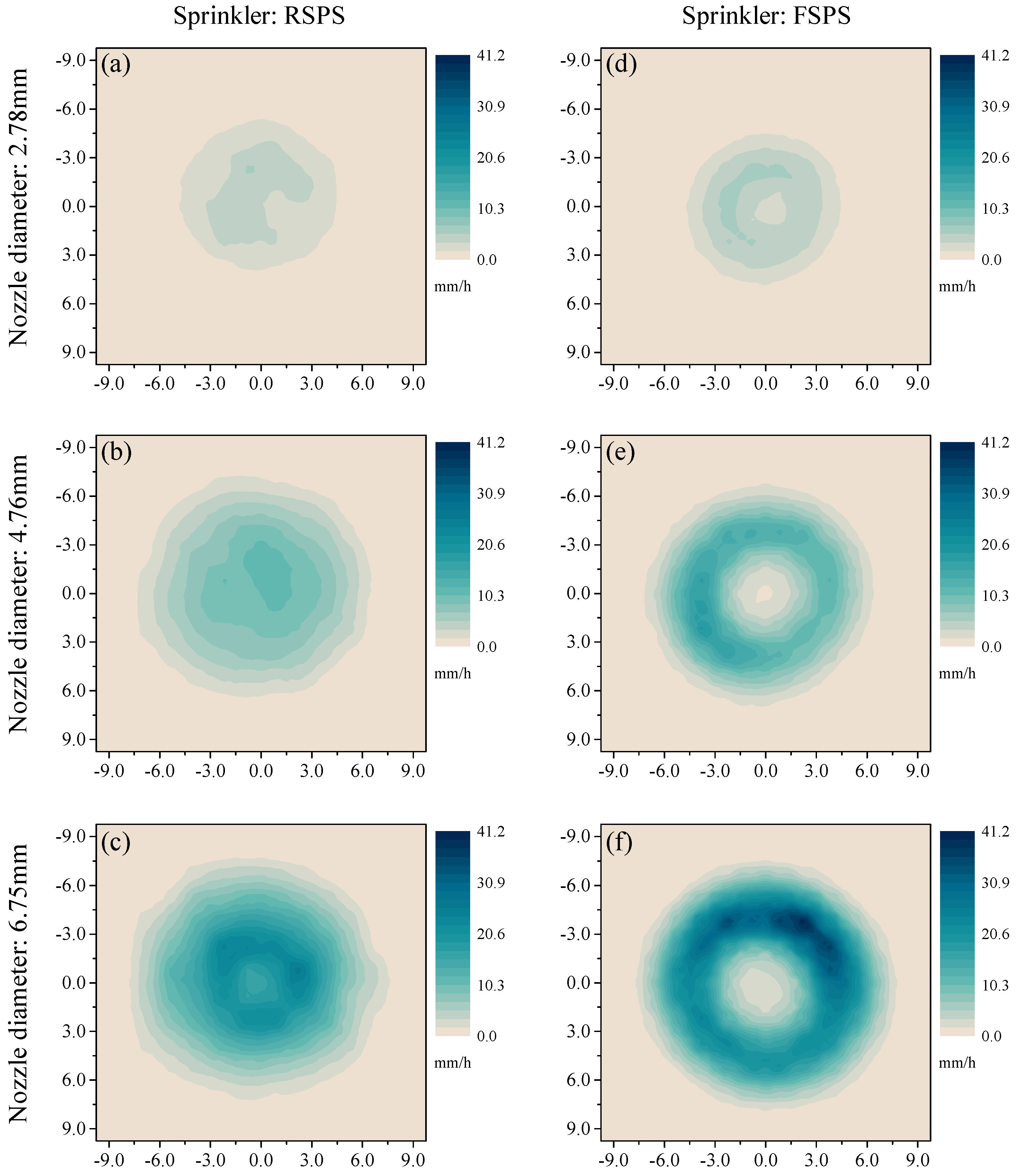
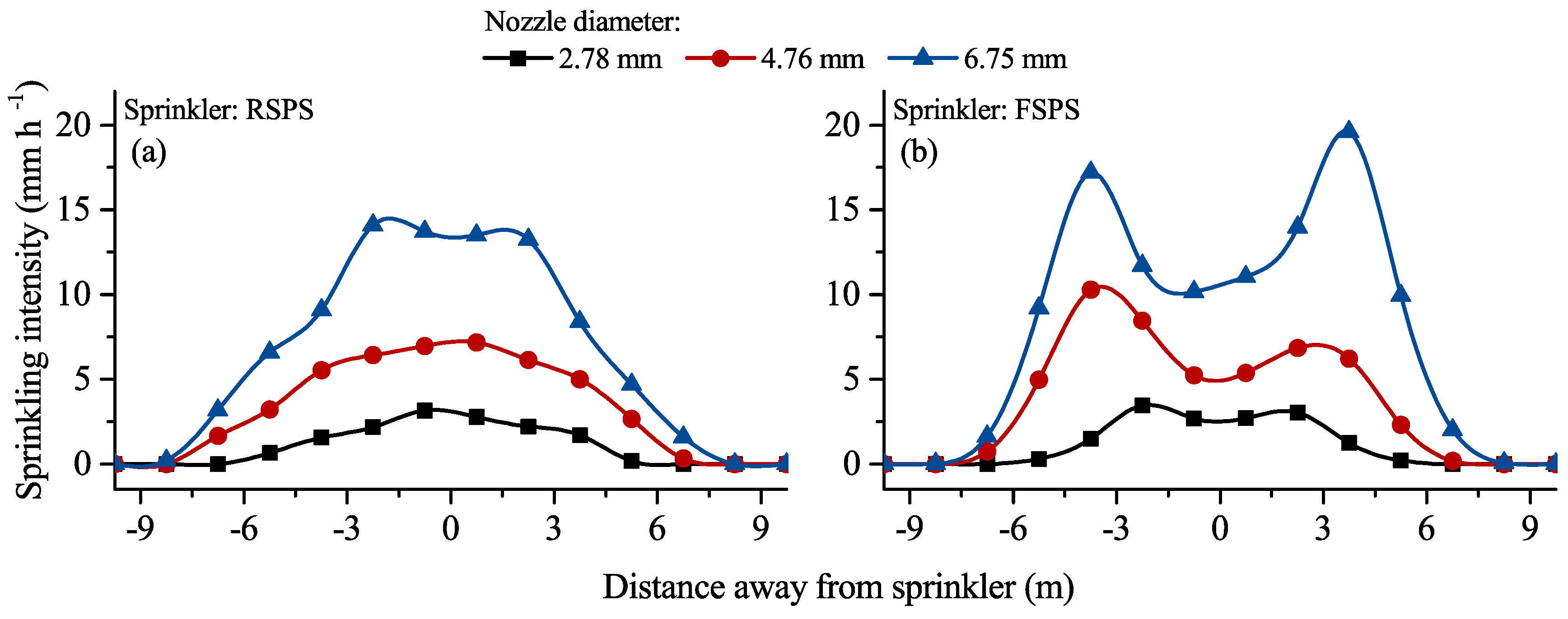
Water distributions between individual RSPSs and FSPSs showed distinct patterns. RSPSs distributed the most water around the sprinkler, whereas FSPSs distributed most water over a ring-shaped region at periphery of the sprinkler. The radial water distribution showed single-peak and double-peak patterns for RSPSs and FSPSs respectively. The effective wetted radiuses of RSPSs and FSPSs were 4.88–7.05 m and 5.02–6.85 m with 2.78, 4.76 and 6.75 mm diameter nozzles being installed, respectively.
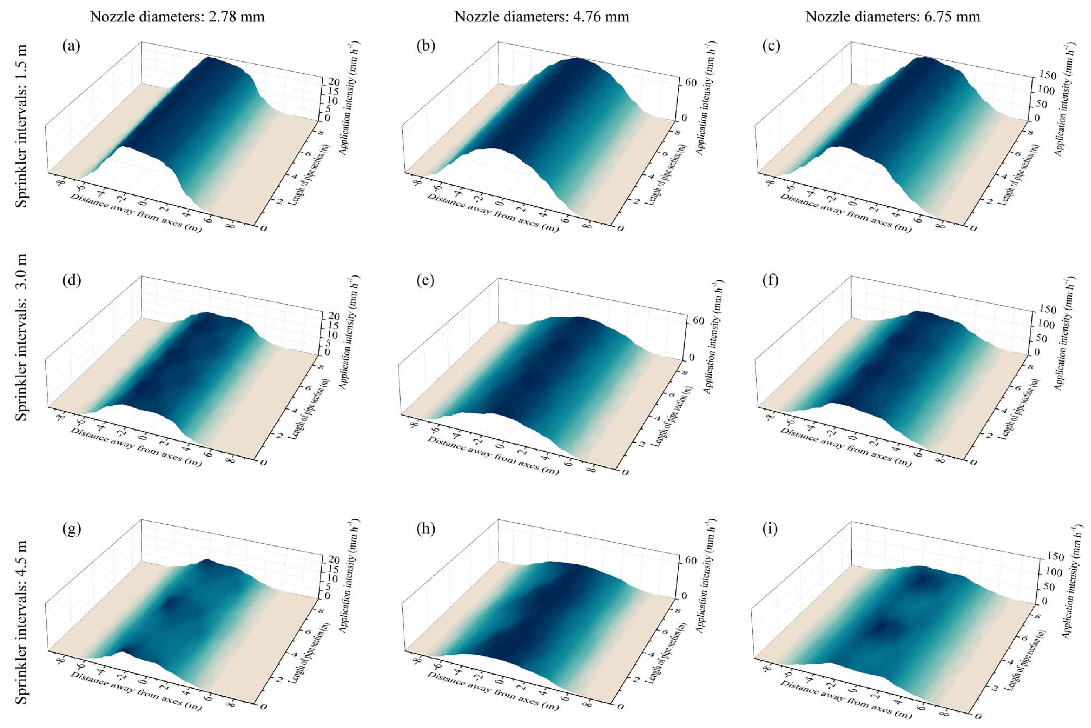
RSPS PS distributed most water around their central axes, and the applied water volumes reduced gradually with the increasing distance from the axes. FSPS PSs distributed the most water over both sides of their axes symmetrically, and lower volumes were distributed around the axes. When the sprinkler intervals increased to 4.5 m, the continuities of water distribution along the axes of the PSs decreased. The CUCs of RSPS PSs and FSPS PSs were 44.7%–51.0% and 40.3%–58.0% respectively under different nozzle diameters (2.78, 4.76 and 6.75 mm) and sprinkler intervals (1.5, 3.0 and 4.5 m).
CUCs of RSPS FCIA were 85.8%, 89.3% and 91.7% under sprinkler intervals of 1.5, 3.0 and 4.5 m, respectively, and CUCs of FSPS FCIAs were 85.8%, 86.2% and 85.8% under sprinkler intervals of 1.5, 3.0 and 4.5 m, respectively. The CUCs of RSPS FCIAs were 3.1% and 6.2% higher than that of FSPS FCIAs when the sprinkler intervals were 3.0 and 4.5 m, respectively. In the center pivot, RSPSs could accommodate larger sprinkler intervals in comparison to FSPS, but also maintained a superior sprinkling performance.
Moreover, works should be conducted to explore the different crop yield, crop quality, soil moisture dynamics and soil moisture distributions between using RSPS and FSPS, under conditions of real commercial center pivots. It might be worthwhile to analyze and compare the cost effectiveness by different types.

Acknowledgments

This work was supported by the National Natural Science Foundation of China (No. 51379011). The authors would like to thank the support provided by the staff and technicians associated with the Clover Group Shuangqiao Experimental Base: Yishan Liu, Jianming Sun and Pai Hou. The utilization of certain products in this study does not imply endorsement of any of them.

Author Contributions

Jian Jiao and Derong Su conceived and designed the experiments; Jian Jiao, Yadong Wang and Liliang Han performed the experiments; and Jian Jiao analyzed the data and wrote the paper. Both authors read and approved the manuscript.

Conflicts of Interest

The authors declare no conflict of interest. The founding sponsors had no role in the design of the study; in the collection, analyses, or interpretation of data; in the writing of the manuscript, and in the decision to publish the results.

References

  1. Wang, M.L.; Yang, C.; Hu, X.D.; Shi, Z.Z. Conception of alfalfa industry development influencing on food security. Pratacultural Sci. 2012, 29, 1936–1940. [Google Scholar]
  2. Valipour, M. Variations of land use and irrigation for next decades under different scenarios. IRRIGA 2016, 1, 262–288. [Google Scholar] [CrossRef]
  3. Valipour, M. How do different factors impact agricultural water management? Open Agric. 2016, 1. [Google Scholar] [CrossRef]
  4. Valipour, M. Evolution of irrigation-equipped areas as share of cultivated areas. Irrig. Drain. Syst. Eng. 2013, 2, e114. [Google Scholar] [CrossRef]
  5. Sun, H.R.; Liu, G.R.; Zhang, Y.J.; Gao, F.; Lu, T.L.; Han, J.G. Water requirement, water consumption, water requirement rate, water consumption rate and water use efficiency of alfalfa. Pratacultural Sci. 2005, 22, 24–30. [Google Scholar]
  6. Valipour, M. How much meteorological information is necessary to achieve reliable accuracy for rainfall estimations? Agriculture 2016, 6, 53. [Google Scholar] [CrossRef]
  7. Valipour, M. Increasing irrigation efficiency by management strategies: Cutback and surge irrigation. ARPN J. Agric. Biol. Sci. 2013, 8, 35–43. [Google Scholar]
  8. Yannopoulos, S.; Lyberatos, G.; Theodossiou, N.; Li, W.; Valipour, M.; Tamburrino, A.; Angelakis, A. Evolution of water lifting devices (pumps) over the centuries worldwide. Water 2015, 7, 5031–5060. [Google Scholar] [CrossRef]
  9. Dilshad, B.; William, L.K.; Tsz Him, L.; Suat, I.; Derrel, L.M. Energy conservation using variable-frequency drives for center-pivot irrigation: Standard systems. Trans. Asabe 2017, 60, 95–106. [Google Scholar]
  10. King, B.A. Moving spray-plate center-pivot sprinkler rating index for assessing runoff potential. Trans. ASABE 2016, 59, 225–237. [Google Scholar]
  11. Montero, J.; Martinez, A.; Valiente, M.; Moreno, M.A.; Tarjuelo, J.M. Analysis of water application costs with a centre pivot system for irrigation of crops in spain. Irrig. Sci. 2013, 31, 507–521. [Google Scholar] [CrossRef]
  12. King, B.; Wall, R.; Karksy, T. Center-pivot irrigation system for independent site-specific management of water and chemical application. Appl. Eng. Agric. 2009, 25, 198. [Google Scholar]
  13. Xiutang, Y.; Yisong, D.; Caiyou, L.; Peiling, Y.; Dechao, Z.; Yongsheng, H.; Zhandi, G. Sprinkler configuration method and mathematical model of center-pivot irrigation system. Trans. Chin. Soc. Agric. Eng. 2007, 2007, 117–121. [Google Scholar]
  14. Ouazaa, S.; Latorre, B.; Burguete, J.; Serreta, A.; Playán, E.; Salvador, R.; Paniagua, P.; Zapata, N. Effect of the start–stop cycle of center-pivot towers on irrigation performance: Experiments and simulations. Agric. Water Manage. 2015, 147, 163–174. [Google Scholar] [CrossRef]
  15. Kayad, A.G.; Al-Gaadi, K.A.; Tola, E.; Madugundu, R.; Zeyada, A.M.; Kalaitzidis, C. Assessing the spatial variability of alfalfa yield using satellite imagery and ground-based data. PLoS ONE 2016, 11, e0157166. [Google Scholar] [CrossRef] [PubMed]
  16. Al-Gaadi, K.A.; Hassaballa, A.A.; Tola, E.; Kayad, A.G.; Madugundu, R.; Alblewi, B.; Assiri, F. Prediction of potato crop yield using precision agriculture techniques. PLoS ONE 2016, 11, e0162219. [Google Scholar] [CrossRef] [PubMed]
  17. Yan, H.J.; Bai, G.; He, J.Q.; Lin, G. Influence of droplet kinetic energy flux density from fixed spray-plate sprinklers on soil infiltration, runoff and sediment yield. Biosyst. Eng. 2011, 110, 213–221. [Google Scholar] [CrossRef]
  18. Haijun, Y.; Jing, M.; Zhipeng, W. Design and field experiment on fertilizer injection device in center pivot irrigation system. Trans. Chin. Soc. Agric. Mach. 2015, 9, 100–106. [Google Scholar]
  19. Musick, J.; Pringle, F.; Walker, J. Sprinkler and furrow irrigation trends-texas high plains. Appl. Eng. Agric. 1988, 4, 46–52. [Google Scholar] [CrossRef]
  20. Sayyadi, H.; Nazemi, A.H.; Sadraddini, A.A.; Delirhasannia, R. Characterising droplets and precipitation profiles of a fixed spray-plate sprinkler. Biosyst. Eng. 2014, 119, 13–24. [Google Scholar] [CrossRef]
  21. Sourell, H.; Faci, J.; Playán, E. Performance of rotating spray plate sprinklers in indoor experiments. J. Irrig. Drain. Eng. 2003, 129, 376–380. [Google Scholar] [CrossRef]
  22. Dukes, M.D. Effect of wind speed and pressure on linear move irrigation system uniformity. Appl. Eng. Agric. 2006, 22, 541–548. [Google Scholar] [CrossRef]
  23. Hanson, B.; Orloff, S. Rotator nozzles more uniform than spray nozzles on center-pivot sprinklers. Calif. Agric. 1996, 50, 32–35. [Google Scholar] [CrossRef]
  24. Tarjuelo, J.M.; Montero, J.; Honrubia, F.T.; Ortiz, J.J.; Ortega, J.F. Analysis of uniformity of sprinkle irrigation in a semi-arid area. Agric. Water Manag. 1999, 40, 315–331. [Google Scholar] [CrossRef]
  25. Dukes, M.; Perry, C. Uniformity testing of variable-rate center pivot irrigation control systems. Precis. Agric. 2006, 7, 205–218. [Google Scholar] [CrossRef]
  26. Brito, R.A.; Willardson, L.S. Sprinkler irrigation uniformity requirements for the elimination of leaching. Trans. ASAE 1982, 25, 1258–1261. [Google Scholar] [CrossRef]
  27. Dechmi, F.; Playán, E.; Cavero, J.; Faci, J.; Martínez-Cob, A. Wind effects on solid set sprinkler irrigation depth and yield of maize (zea mays). Irrig. Sci. 2003, 22, 67–77. [Google Scholar] [CrossRef]
  28. Stern, J.; Bresler, E. Nonuniform sprinkler irrigation and crop yield. Irrig. Sci. 1983, 4, 17–29. [Google Scholar] [CrossRef]
  29. Sanchez, I.; Zapata, N.; Faci, J.M. Combined effect of technical, meteorological and agronomical factors on solid-set sprinkler irrigation: I. Irrigation performance and soil water recharge in alfalfa and maize. Agric. Water Manag. 2010, 97, 1571–1581. [Google Scholar] [CrossRef]
  30. Yan, H.; Jin, H.; Qian, Y. Characterizing center pivot irrigation with fixed spray plate sprinklers. Sci. China Technol. Sci. 2010, 53, 1398–1405. [Google Scholar] [CrossRef]
  31. Kincaid, D. Application rates from center pivot irrigation with current sprinkler types. Appl. Eng. Agric. 2005, 21, 605–610. [Google Scholar] [CrossRef]
  32. Playán, E.; Garrido, S.; Faci, J.M.; Galán, A. Characterizing pivot sprinklers using an experimental irrigation machine. Agric. Water Manag. 2004, 70, 177–193. [Google Scholar] [CrossRef]
  33. Ortíz, J.N.; Juan, J.A.; Tarjuelo, J.M. Analysis of water application uniformity from a centre pivot irrigator and its effect on sugar beet (beta vulgaris l.) yield. Biosyst. Eng. 2010, 105, 367–379. [Google Scholar] [CrossRef]
  34. Ortíz, J.N.; Tarjuelo, J.M.; de Juan, J.A. Characterisation of evaporation and drift losses with centre pivots. Agric. Water Manag. 2009, 96, 1541–1546. [Google Scholar] [CrossRef]
  35. Deboer, D.W.; Monnens, M.J. Estimation of drop size and kinetic energy from a rotating spray-plate sprinkler. Trans. ASAE 2001, 44, 1571–1580. [Google Scholar] [CrossRef]
  36. DeBoer, D. Drop and energy characteristics of a rotating spray-plate sprinkler. J. Irrig. Drain. Eng. 2002, 128, 137–146. [Google Scholar] [CrossRef]
  37. Stambouli, T.; Martinez-Cob, A.; Faci, J.M.; Howell, T.; Zapata, N. Sprinkler evaporation losses in alfalfa during solid-set sprinkler irrigation in semiarid areas. Irrig. Sci. 2013, 31, 1075–1089. [Google Scholar] [CrossRef]
  38. Stambouli, T.; Zapata, N.; Faci, J.M. Performance of new agricultural impact sprinkler fitted with plastic nozzles. Biosyst. Eng. 2014, 118, 39–51. [Google Scholar] [CrossRef]
  39. Sprayers-General Requirement and Test Methods: 8026. Available online: https://www.evs.ee/preview/iso-8026-2009-en.pdf (accessed on 10 February 2017).
  40. ASAE. S 398.1. Procedure for sprinkler testing and performance reporting. In ASAE Standards; ASAE: St. Joseph, MI, USA, 1985. [Google Scholar]
  41. Clark, G.A.; Srinivas, K.; Rogers, D.H.; Stratton, R.; Martin, V.L. Measured and simulated uniformity of low drift nozzle sprinklers. Trans. ASAE 2003, 46, 321–330. [Google Scholar] [CrossRef]
  42. Zhu, X.; Yuan, S.; Jiang, J.; Liu, J.; Liu, X. Comparison of fluidic and impact sprinklers based on hydraulic performance. Irrig. Sci. 2015, 33, 367–374. [Google Scholar] [CrossRef]
  43. Han, W.; Fen, H.; Wu, P.; Yang, Q. Evaluation of sprinkler irrigation uniformity by double interpolation using cubic splines. In Proceedings of the 2007 ASAE Annual Meeting, Chicago, IL, USA, 8–9 August 2007. [Google Scholar]
  44. Christiansen, J. Irrigation by Sprinkling. California Agricultural Experiment Station Bulletin 670; University of California: Berkeley, CA, USA, 1942. [Google Scholar]
  45. Valín, M.I.; Cameira, M.R.; Teodoro, P.R.; Pereira, L.S. Depivot: A model for center-pivot design and evaluation. Comput. Electron. Agric. 2012, 87, 159–170. [Google Scholar] [CrossRef]
  46. Tabuada, M.A. Hydraulics of center-pivot laterals: Complete analysis of friction head loss. J. Irrig. Drain. Eng. 2011, 137, 513–523. [Google Scholar] [CrossRef]
  47. Valiantzas, J.D. Modified hazen–williams and darcy–weisbach equations for friction and local head losses along irrigation laterals. J. Irrig. Drain. Eng. 2005, 131, 342–350. [Google Scholar] [CrossRef]
  48. Yan, H.; Yao, P.; Zhu, Y.; Yu, P. Nozzle configuration and software for center pivot irrigation system. Trans. Chin. Soc. Agric. Mach. 2011, 42, 84–88. [Google Scholar]
  49. Yan, H.J.; Xiao, J.W.; Li, W.Y.; Li, Y.C.; Hou, Y.S. Droplet size distributions of low-pressure damping sprinklers used in center-pivot irrigation systems. J. Hydraul. Eng. 2014, 45, 467–473. [Google Scholar]
  50. Omary, M.; Camp, C.R.; Sadler, E.J. Center pivot irrigation system modification to provide variable water application depths. Trans. ASAE 1997, 13, 235–239. [Google Scholar]
  51. King, B.; Bjorneberg, D. Evaluation of potential runoff and erosion of four center pivot irrigation sprinklers. Appl. Eng. Agric. 2011, 75–85. [Google Scholar] [CrossRef]
  52. Zhao, W.; Li, J.; Yang, R.; Li, Y. Field evaluation of water distribution characteristics of variable rate center pivot irrigation system. Trans. Chin. Soc. Agric. Eng. 2014, 30, 53–62. [Google Scholar]
Figure 1. Schematic of the experimental system for measuring water distribution of rotating and fixed spray plate sprinklers.
Applsci 07 00421 g001
Figure 2. Catch can arrangements for measurements of water distribution with rotating (a) and fixed (b) spray plate sprinklers. Asterisks indicate the locations of sprinklers.
Applsci 07 00421 g002
Figure 3. Nozzle configuration for the simulated center pivot irrigation system with different sprinkler intervals: 1.5, 3.0, and 4.5 m.
Applsci 07 00421 g003
Figure 4. The estimated average radial application patterns for the unmeasured nozzles equipped in RSPSs (a) and FSPSs (b). The three solid lines in each figure indicated the three actual measured nozzles: 6.75, 4.76 and 2.78 mm, appearing from top to bottom respectively.
Applsci 07 00421 g004
Figure 5. Water distribution characteristics of individual rotating spray plate sprinklers (RSPSs) and fixed spray plate sprinklers (FSPSs). The figures in different columns and rows indicate different sprinkler types (RSPS and FSPS) and nozzle diameters (2.78, 4.76, and 6.75 mm): RSPS—2.78 (a), RSPS—4.76 (b), RSPS—6.75 (c), FSPS—2.78 (d), FSPS—4.76 (e) and FSPS—6.75 (f).
Applsci 07 00421 g005
Figure 6. Application intensity in radii of individual rotating spray plate sprinklers (RSPSs) (a), and fixed spray plate sprinklers (FSPSs) (b).
Applsci 07 00421 g006
Figure 7. Water distribution characteristics of same-nozzle-sprinkler pipe sections with rotating spray plate sprinklers (RSPSs). The figures in different columns and rows indicate different nozzle diameters (2.78, 4.76, and 6.75 mm) and sprinkler intervals (1.5, 3.0, and 4.5 m): RSPS—2.78—1.5 (a), RSPS—4.76—1.5 (b), RSPS—6.75—1.5 (c), RSPS—2.78—3.0 (d), RSPS—4.76—3.0 (e), RSPS—6.75—3.0 (f), RSPS—2.78—4.5 (g), RSPS—4.76—4.5 (h) and RSPS—6.75—4.5 (i).
Applsci 07 00421 g007
Figure 8. Water distribution characteristics of same-nozzle-sprinkler pipe sections with fixed spray plate sprinklers (FSPSs). The figures in different columns and rows indicate different nozzle diameters (2.78, 4.76, and 6.75 mm) and sprinkler intervals (1.5, 3.0, and 4.5 m): FSPS—2.78—1.5 (a), FSPS—4.76—1.5 (b), FSPS—6.75—1.5 (c), FSPS—2.78—3.0 (d), FSPS—4.76—3.0 (e), FSPS—6.75—3.0 (f), FSPS—2.78—4.5 (g), FSPS—4.76—4.5 (h) and FSPS—6.75—4.5 (i).
Applsci 07 00421 g008
Table 1. Basic performance parameters of rotating and fixed spray plate sprinklers (RSPSs and FSPSs).
SprinklerNozzle Diameter (mm)Pressure Range (kPa)Flow Range (m3·h−1)Wetted Radius 1 (m)
RSPS (Nelson R3000) 22.78–9.92 mm98–1960.293–5.4705–9
FSPS (Nelson D3000) 21.79–9.92 mm40–2740.077–5.4704–6
1 for the case when the height of sprinkler is 80 cm; 2 R3000 and D3000 are types of RSPSs and FSPSs respectively.
Table 2. Configuration parameters of the test sprinklers.
SprinklerTypeSpray PlateElevation Angle and TrajectorySprinkler Height (cm)Nozzle Size (mm)Number of Grooves on Spray Plate
RSPS 1R3000Brown
Applsci 07 00421 i001
Medium and multi-trajectory802.7812
4.7612
6.7512
FSPS 2D3000Blue
Applsci 07 00421 i002
Slight and uniform trajectory802.7836
4.7636
6.7536
1 RSPS, rotating spray plate sprinkler; 2 FSPS, fixed spray plate sprinkler.
Table 3. Configurations and operating parameters of the simulated center pivot irrigation system.
ConfigurationsConfiguration ParametersOperating Parameters
Sprinkling RadiusPressure of End SprinklerEnd GunPipe DiameterSprinkler IntervalsSprinkling VolumesSprinkling IntensityCycle Length
Parameters300 m103 kPaNone165 mm4.5 m10 mm10 mm/h36 h
Table 4. Basic information regarding experimental measurements.
Sprinklers and Nozzles 1Number of MeasurementsAverage Wind Speed (m/s)
RSPS—2.7840.7
RSPS—4.7680.8
RSPS—6.7540.6
FSPS—2.7860.4
FSPS—4.76120.7
FSPS—6.7570.4
1 RSPS, rotating spray plate sprinkler; FSPS, fixed spray plate sprinkler; 2.78, 4.76 and 6.75 indicate the nozzle diameters of 2.78 mm, 4.76 mm and 6.75 mm respectively.
Table 5. Wetted radii of rotating spray plate sprinklers (RSPSs) and fixed spray plate sprinklers (FSPSs) with nozzles of differing diameters installed.
SprinklerWetted Radius (m)
2.78-mm-Diameter Nozzle4.76-mm-Diameter Nozzle6.75-mm-Diameter Nozzle
RSPS4.88 ± 0.22a6.40 ± 0.11b7.05 ± 0.09c
FSPS5.02 ± 0.06a6.33 ± 0.07b6.85 ± 0.15c
Note: Lowercase in differences represents significant different level among nozzle diameters (P < 0.05).
Table 6. Christiansen coefficients of uniformities (CUCs) of same-nozzle-sprinkler pipe sections (PSs) of rotating spray plate sprinklers (RSPSs) and fixed spray plate sprinklers (FSPSs) with differing nozzle diameters and sprinkler intervals.
Nozzle DiameterSprinkler IntervalCUC of PSs with the Same Nozzle Diameter
RSPSFSPS
2.78 mm1.5 m47.3%40.4%
3.0 m46.1%40.3%
4.5 m51.0%41.3%
4.76 mm1.5 m48.3%43.9%
3.0 m48.0%44.0%
4.5 m48.0%41.6%
6.75 mm1.5 m45.1%58.0%
3.0 m44.7%58.0%
4.5 m45.1%50.9%
Table 7. Christiansen coefficients of uniformities (CUCs) for the full circular irrigated area for the simulated center pivot irrigation system.
Sprinkler TypesSprinkler Intervals and Required Sprinkler Quantities
1.5 m/1913.0 m/964.5 m/64
RSPS85.8%89.3%91.7%
FSPS85.8%86.2%85.8%
Notes: RSPS, rotating spray plate sprinkler; FSPS, fixed spray plate sprinkler.

