
Damage Index Calibration of Frame-Supported Concealed Multi-Ribbed Wall Panels with Energy-Efficient Blocks

1
School of Engineering and Technology, China University of Geosciences (Beijing), No. 29, Xueyuan Road, Haidian District, Beijing 100083, China
2
College of Architecture and Civil Engineering, Beijing University of Technology, No. 100, Pingleyuan, Chaoyang District, Beijing 100124, China
3
Academy of Railway Sciences, Scientific & Technological Information Research Institute, No. 2, Daliushu Road, Haidian District, Beijing 100081, China
*
Author to whom correspondence should be addressed.
Appl. Sci. 2017, 7(5), 453; https://doi.org/10.3390/app7050453
Submission received: 14 March 2017
/
Revised: 23 April 2017
/
Accepted: 26 April 2017
/
Published: 28 April 2017
(This article belongs to the Section Materials Science and Engineering)
Abstract
:In this paper, we carry out low-reversed cyclic loading tests on differently-structured frame-supported concealed multi-ribbed wall panels with energy-efficient blocks. Models for evaluating damage performance are introduced for comparative study, in an effort to identify the preferable model for such a structure. To this end, the paper uses OpenSees, a nonlinear finite element software that can accurately depict the mechanical performance of a structure, both to calculate the necessary mechanical parameters and to verify the damage model of interest. In this paper, we determine the numerical ranges for the damage index at different stages of accumulative damage, attaching detailed descriptions on a stage-by-stage basis. Then, we offer suggestions for structure restoration according to these indices.
1. Introduction
As cities and towns widely adopt structural designs, in which large spaces are present at the bottom part of the frontage building, experiments that focus on earthquake damage have been conducted on large scales [1,2,3]. The results indicate that as the frame-supported masonry structure enters the yielding stage, the load-bearing wall absorbs the majority of the seismic energy. Although the structural columns and ring beams help mitigate earthquake damage to a certain degree, the brittle material that is applied may induce a sudden change in internal force, which, in turn, weakens the structure as a whole. Severe damage then occurs, as frame-supported columns (FS columns) collapse and frame-supported beams (FS beams) begin to crack slightly. In other words, the masonry structure at this point fails to deliver the design scheme, in which strong columns support yet-so-strong beams.
In addition, it must to be pointed out that as the country works to design better large-bay residences, the materials that are selected for manufacturing load-bearing walls (porous bricks and masonry blocks, for instance) tend to be underused because adjustments are still needed with respect to the distribution of force and stiffness at key areas. Simultaneously, widely applied clay-brick masonry has been found to be harmful to the adjacent farmland, which strains resources and undermines environmental-protection efforts [4,5]. In comparison, frame-supported shear wall structures use a design scheme, in which the upper part is relatively stronger than the lower part. Therefore, under lateral seismic influence, the shear wall begins to crack diagonally. As the structure reaches its loading limit, a drop in stiffness is noticed, while deformation largely accumulates in the lower part, which is the primary location for the build-up of seismic energy. In addition to the enormous amounts of required materials, the complex construction procedure and high cost of building has prevented this method from reaching underdeveloped areas of the country, not to mention small- and medium-sized cities and towns [6,7]. With the above-mentioned points in mind, we believe that a clear, correct, and quantified grasp of damage mechanisms is the key to the seismic stability of structures with interim layers.
On this basis, we suggest a concealed multi-ribbed (CMR) wall panel with energy-efficient embedded blocks be used in the construction of buildings with large spaces in the bottom. This will help create a new structural system: a frame-supported concealed multi-ribbed (FSCMR) wall panel structure with energy-efficient blocks. Based on the progress made in the current stage, we took a performance-oriented approach to studying the CMR wall unit. The experimental data have allowed us to quantify damage-resistance performance and determine an approximate method for damage analysis under seismic influence. In the meantime, focusing on the damage mitigation unit for the CMR panel, we have investigated the panel failure process, as well as the split ratio of energy consumption, which has proven to be helpful in the study of the collapse resistance of the overall structure [8]. Despite the academic accomplishments achieved in the damage evaluation of the panel unit and its main components, FSCMR wall panel structures remain an overlooked subject [9]. Considering this, the study imposes low-reversed cyclic loading on the structure and analyses the mechanisms of the accumulative damage that follows. It aims to identify the damage model accordingly and unveil the rules for damage evaluation, in order to facilitate the future seismic design and evaluation of the FSCMR wall panel.
2. FSCMR Wall Panel Structure
2.1. CMR Wall Panel Structure
In response to increasing global temperatures, all countries are committed to encouraging the development of low-carbon industries. As structural, material, and construction techniques have raised the international criteria for low-carbon residences, research teams have incorporated building performance in terms of energy consumption and collapse resistance, and have developed a CMR wall panel system. The structure stands in line with energy-saving reforms, overall trends of residence industrialization, and strategic requirements for sustainable development.
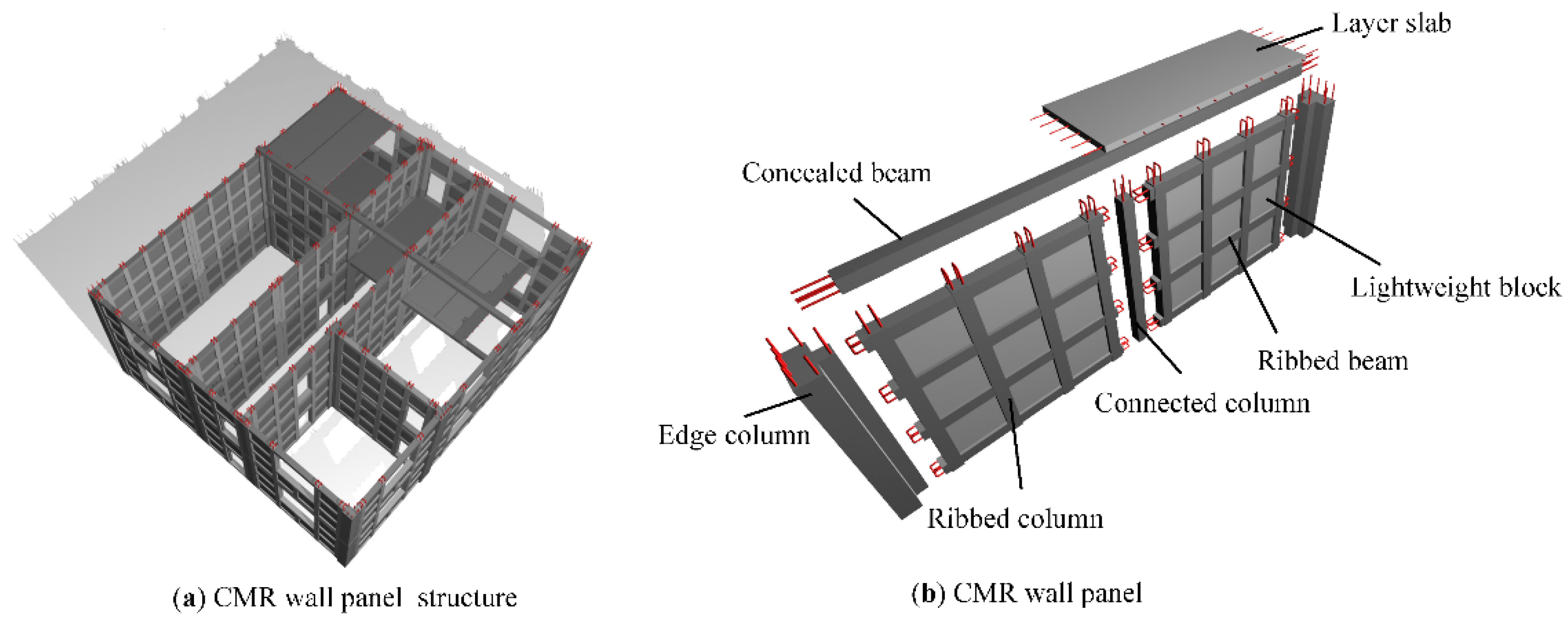
With a layer-by-layer embedded design, a CMR wall panel structure is composed of a cast-in-situ edge frame, layer slabs, and a prefabricated CMR panel. The latter, as a newly-proposed composite panel, uses lightweight blocks with a low elasticity modulus embedded in the CMR frame, manufactured by densely arranged reinforced-concrete beams and columns. The edge frame (constructed from concrete edge columns, connected columns, and concealed beams) both bonds and simultaneously restrains the CMR panel [10]. Thereby, the above-mentioned parts comprise the major force-bearing members of the structure, namely the CMR wall panel (see Figure 1). Floor slab of cast-in-situ reinforced concrete shall be applied as layer slab, the steel bars of which shall be well connected with the concrete beams, the edge columns and the connected columns. The force bearing calculation and construction procedures of layer slab shall follow the rules set out in the National Standard for People’s Republic of China (GB50011-2010 and GB50010-2010) [11,12].
Compared to its counterparts, the CMR wall panel structure stands out for its force-bearing performance, seismic resistance, energy efficiency, temperature insulation, and potential for industrialization [13,14]:
- (1)
- Outstanding structural integrity and working performance;
- (2)
- Exceptional force-bearing performance;
- (3)
- Easy adjustment of structural stiffness;
- (4)
- Multiple seismic lines of defence;
- (5)
- Effective seismic buffer;
- (6)
- Promising prospects for industrialization;
- (7)
- Strong performance in collapse resistance;
- (8)
- A practical, cost-efficient, energy-saving and environmental friendly choice.
Because the residence pilot projects have taken place in Yinchuan, Shanxi, Henan, and many other provinces, the CMR wall panel structure has reached into to every aspect of social production and practice (see Figure 2), and efforts of the country toward this end have yielded both economic and social results [15,16,17]. Under such circumstances, the Ministry of Housing and Urban Development, P.R. China, has issued an industrial standard, The Directive Rules for Concealed Multi-Ribbed Wall Panel Structures with Energy-efficient Blocks, which became effective 1 June 2014 [13].
2.2. Functions of CMR Wall Panel Structure with Energy-Efficient Blocks and Its Manufacture and Assembly
With respect to materials, CMR wall panel structures with energy-efficient blocks are composed of brittle materials with a relatively high stiffness (or in other words, blocks), and of reinforced concrete with fair ductility: the CMR frame and cast-in-place edge frame. Therefore, the overall structure has moderate stiffness, with its force bearing performance falling between that of a frame structure and that of a shear wall structure. Under lateral loading, the blocks with a low modulus of elasticity crack first. However, because of the restraint of the grid, which is formed by the ribbed columns and ribbed beams, blocks consume this energy in friction, which can be considered to be the first seismic line of defence. The ribbed beams and ribbed columns enhance the connectivity of the concealed ribbed frame. Furthermore, with the support of the blocks, the CMR frame offers even greater stiffness in comparison with the cast-in-place edge frame, meaning that the failure of the former occurs before that of the latter. Therefore, the CMR frame can be seen as the second seismic line of defence. At later stages of force bearing, the CMR frame and cast-in-place edge frame cooperate to prevent structure collapse during a major earthquake, which is the final seismic line of defence. The overall CMR wall panel structure is a layered energy consumption system with the following failure pattern: blocks, then CMR frame, then cast-in-place edge frame. In other words, multiple seismic lines of defence are present.
2.3. FSCMR Wall Panel Structure
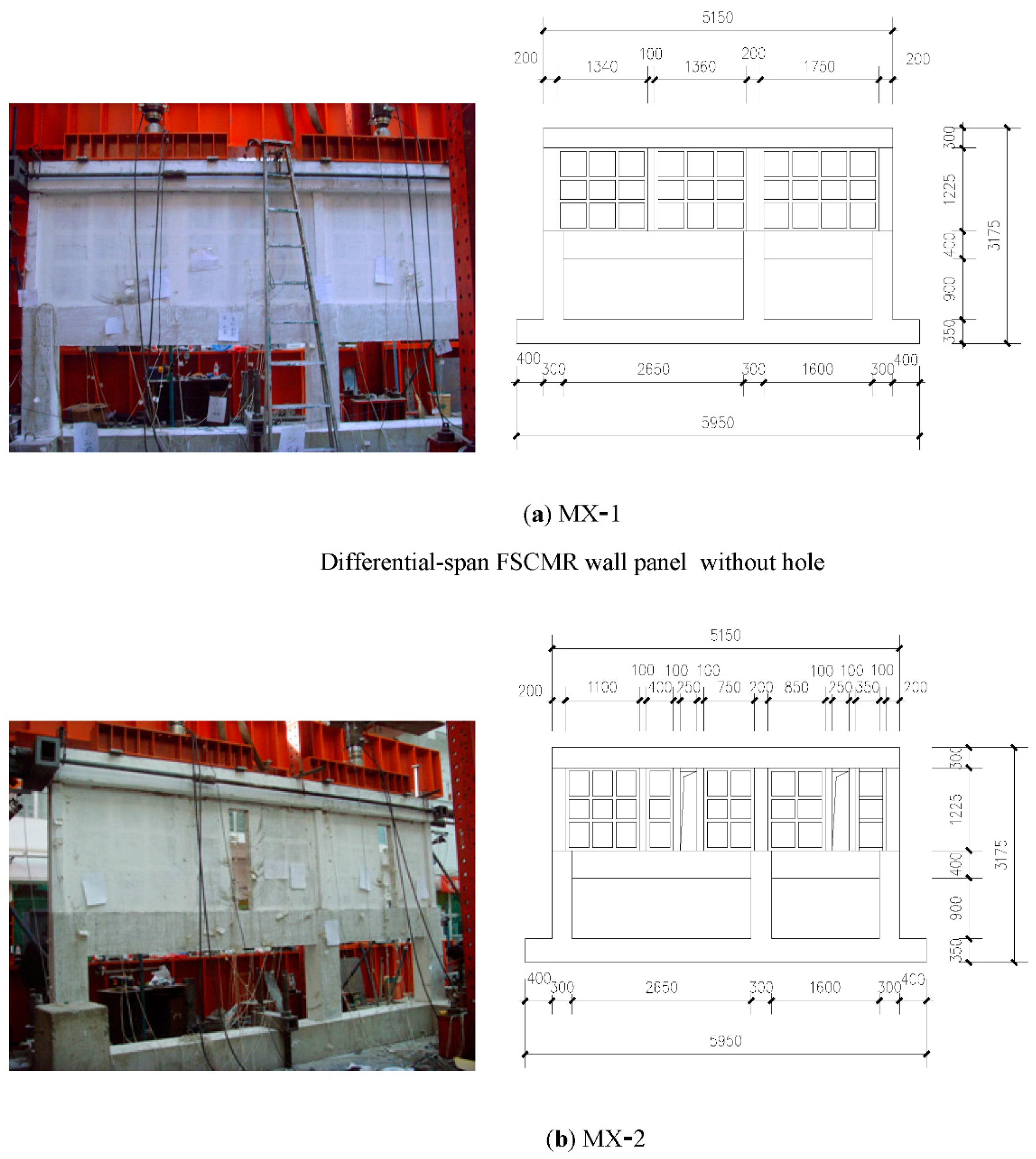
In the study, a CMR wall panel structure is integrated with a large-bottom-space structure, giving rise to a frame-supported CMR wall panel structure with energy-efficient blocks (FSCMR wall panel structure). Two different composite FSCMR wall panels are chosen (see Figure 5 and Table 1) for this study, with ½ reduced prototype scales, and low-reversed cyclic loading tests are carried out. Please see References [15,17] for the experimental procedures and observed phenomena. Later, as the model for damage evaluation is established, the paper makes use of the nonlinear finite element software OpenSees, and adjusts the parameters of concern to simulate force impulsion. In turn, the determined characteristic values help verify the damage model.
3. Damage Evaluation Model for FSCMR Wall Panel Structure
Because of experiments conducted on a large number of reinforced concrete beams and columns, Park, Ang, and Wen et al. [18] created a seismic damage model that depicts the linear superposition of maximum deformation and accumulative energy consumption. The damage index, DIp, is defined as follows:
The model itself is built on the pre-conditions that
- (1)
- the interrelation between maximum deformation and accumulative hysteretic energy is not considered; and
- (2)
- the contribution of maximum deformation and accumulative hysteretic energy to damage follows a linear pattern.
Backed by extensive experimental evidence, the model stands as a well-integrated damage model that considers the effects of damage-induced stiffness degradation, strength degradation, and adhesive sliding on the overall structure. It must be noted that the model introduces the ratio of accumulative hysteretic energy to the product of yield strength and the displacement limit, in order to evaluate the contribution of accumulative hysteretic energy to damage indices. However, in a physical sense, the obtained results are hardly sensible; and, given the under-developed calculation theories, the damage indices fall below accuracy limits.
In this context, this paper introduces [18], and modifies the double-parameter Park–Ang damage model [19,20] in order to analyse and evaluate the damage performance of an FSCMR wall panel structure in the process of energy consumption and seismic mitigation, which is carried out as follows:
- Step 1:
- The modification is conducted under the assumption that the linear superposition of maximum deformation and accumulative hysteretic energy of the Park–Ang model remains unchanged. Under such conditions, the product of the yield strength and the displacement limit in the denominator is replaced by the plastic energy consumption under monotone loading, which has proven to be more physically realistic.
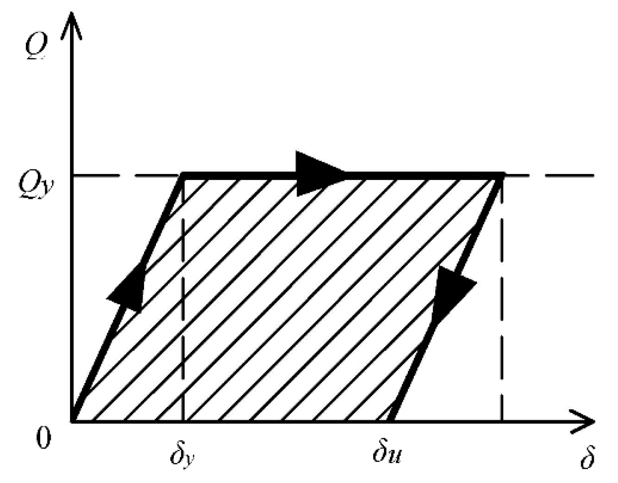
The simplified recoverability model for an elastic-plastic structure under ideal conditions is applied to calculate the plastic capacity of energy consumption under monotone loading, which, as Figure 6 shows, equals the envelope area.
The Park–Ang model is then adjusted accordingly:
The variables in this equation represent the following quantities:
- Qy (δu − δy) is the energy consumption at the limits of the ideal elastic-plastic system under monotone loading;
- Qy is the structural strength at the yielding point;
- δy, δu, δm are the yielding deformation, deformation limit, and maximum deformation;
- ∫dE is the accumulative hysteretic energy of the structure (to the point under calculation);
- β is the weight coefficient of the accumulative hysteretic energy item.
- Step 2:
On the basis of the two damage models mentioned above (see Equations (2) and (3)), the paper introduces displacement as a new parameter, α, and determines the damage model for the FSCMR wall panel as shown below:
As the structure reaches its displacement limit, it is assumed that the damage index DIp stands at 1. Under this assumption, the paper references the measured data for the two FSCMR wall panel pieces and obtains average values of δm, δu, ∫dE, and Qy. Then, with the help of Equation (4), α and β can be obtained (as 0.073 and 0.019, respectively). At this point, the equation can be rewritten as follows:
In this study, the data are then examined, and are compared to the damage indexes calculated by all three models, to allow for the identification of the best FSCMR wall panel structure.
Damage model of ductility degradation
In this model, the damage index is measured using the collected displacement ductility; this theory assumes that damage occurs largely because of the maximum elastic-plastic deformation [23,24].
The damage index DIy is consistent with the expression below:
The variables in this equation represent the following: μm = δm/δy represents the maximum coefficient of deformation ductility; and μu = δu/δy represents the limit coefficient of deformation ductility.
Damage model of stiffness degradation
The paper introduces the concept of using the stiffness ratio for damage evaluation [23,24,25], which gives the results for both the first excursion failure and that of the accumulated damage:
The variables listed above are interpreted as follows: k0 is the preliminary stiffness at the cracking point; and kr is the stiffness that occurs at the lift of impulsion after deformation reaches a maximum displacement.
After the data from all three damage models are collected, the relationship between the damage index and the displacement ratio (or δ/δy) can be determined (see Figure 7).
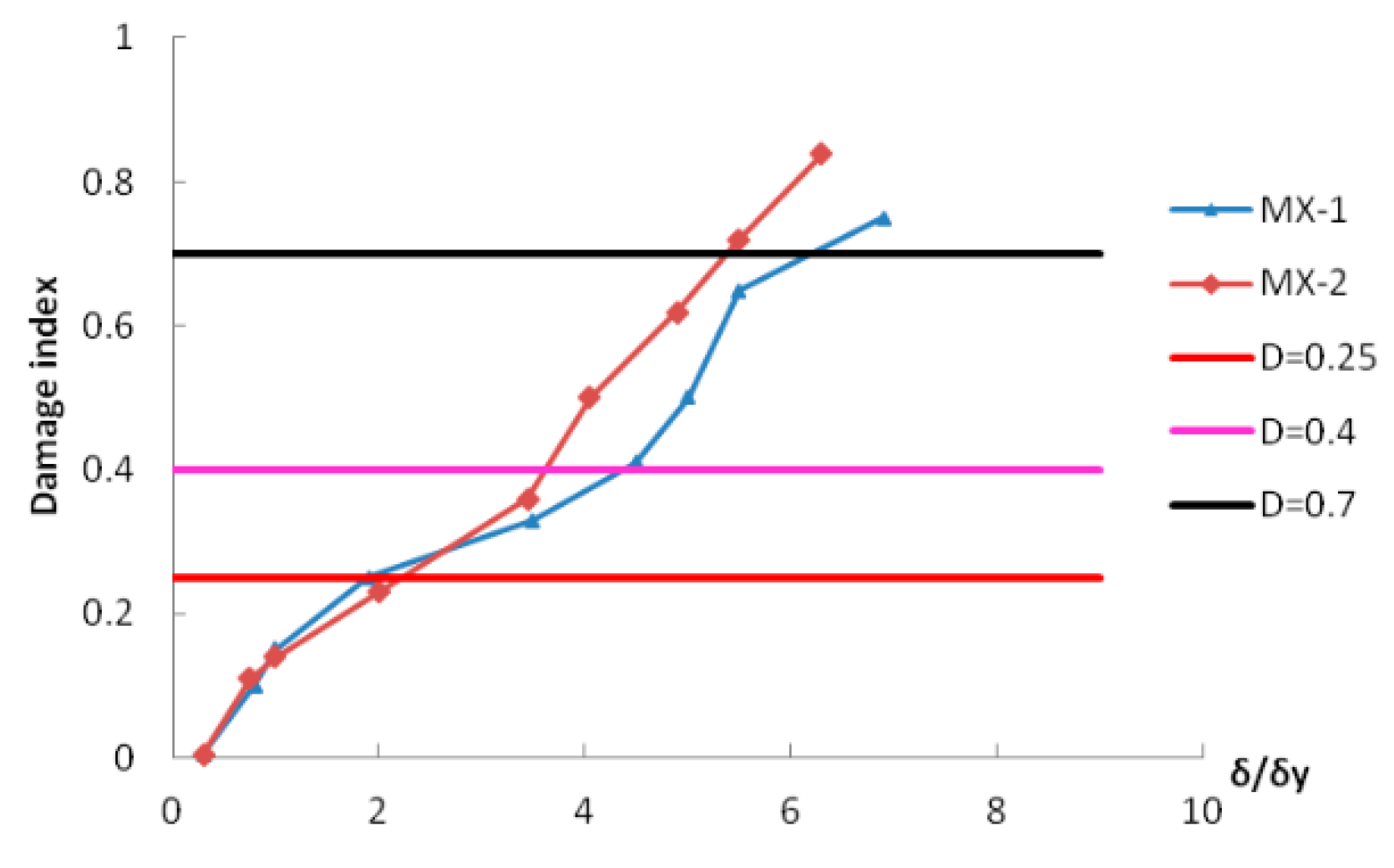
As shown in the figure above, the damage indices calculated by the modified Park–Ang model tend to fall between those of the other two models, which is consistent with the experimental results of the paper. Comparatively, it better depicts the failure processes and damage patterns of FSCMR wall panel structures. Figure 8 shows damage indices for the two specimens.
Figure 8 shows that the two specimens share a relatively similar variation pattern. As δ/δy fluctuates between 0 and 2, the specimens maintain fairly good conditions, with no visible damage on the surface. At this point, the damage index varies between 0 and 0.25. As δ/δy increases to a range of 2 to 4.5, the specimens begin to crack slightly. At this stage of mid-term development, the damage index falls between 0.25 and 0.4. At the next stage (that is, the stage of rapid development), aggravated damage begins to occur. Here, δ/δy tends to stay between 4.5 and 6, while the damage index fluctuates within a range of 0.4 to 0.7. As the experiments continue, the specimens are completely destroyed and have no bearing capacity. Here, the corresponding damage index varies between 0.7 and 1.0.
Backed by different damage models, researchers in the field carried out a large number of experiments to study the force bearing performance of the structures and their members [26,27]. The results clarify the limits of the damage index at different damage stages, where damage that occurs to a reinforced concrete structure under seismic influences is divided into five levels: fairly good, slightly damaged, moderately damaged, severely damaged, and collapsed (see Table 2).
From Table 2, it can be concluded that, compared to a reinforced concrete structure, an FSCMR wall panel structure at any stage of failure generally has a higher damage index. In other words, the deformation of the grid and block largely absorb any seismic energy, meaning that the FSCMR wall panel structure overall performs fairly well in terms of collapse resistance.
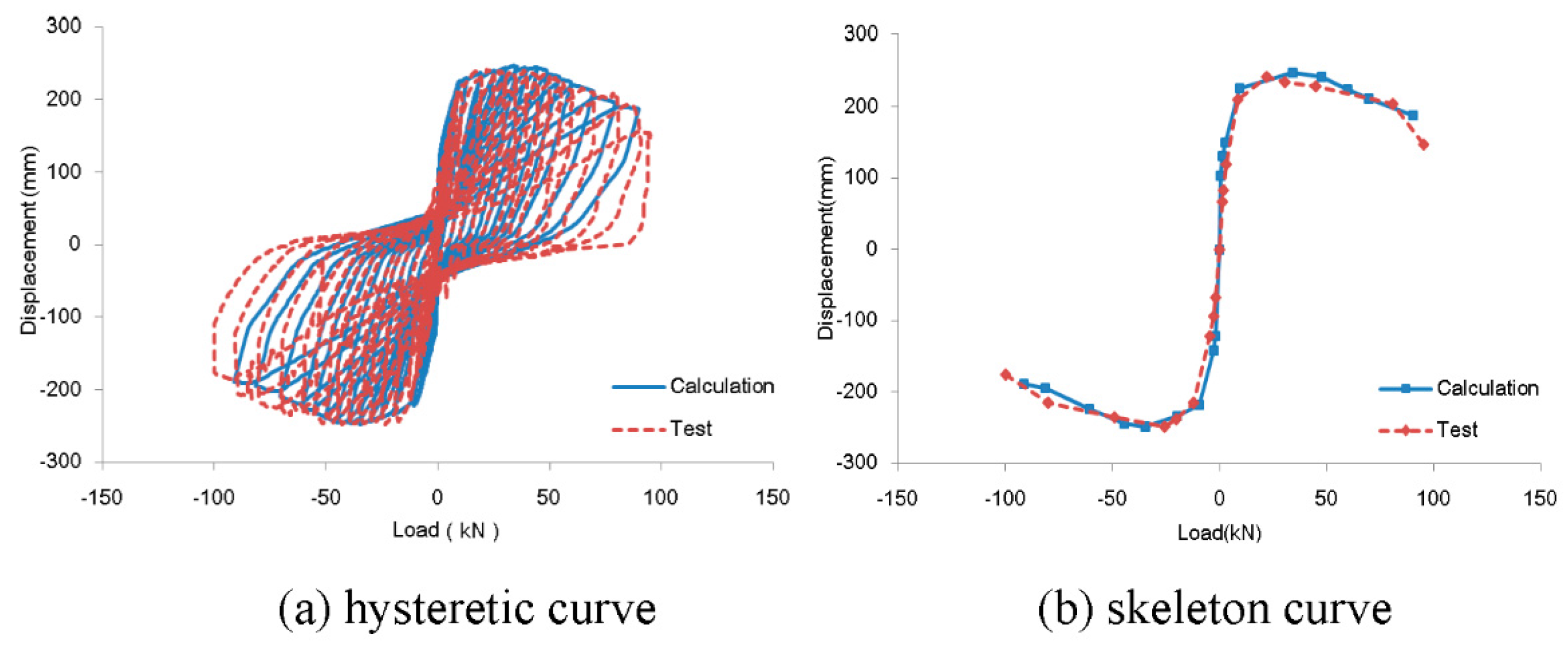
The study, with the help of OpenSees, simulates the hysteresis of an FSCMR wall panel structure under cyclic loading. The simulated results are then compared with collected experimental data (see Figure 9). The accuracy of the model can be verified by examining whether or not the hysteretic curve and skeleton curve coincide. Here, MX-1 is used to specify the procedure. The research team introduces OpenSees in its simulation of specimen physical performance (see Figure 10), using the material-specialized model Concrete02, in which the strength and linear emollescence in tension of concrete is applied in the study of the constitutive relationship of concrete. In contrast, in the uniaxial material model, a hysteretic material is chosen for the simulation of reinforced concrete, as the model does not eliminate stiffness degradation upon the lift of force impulsion and is fully able to reflect the pinching effect. The beam-column unit makes use of the nonlinear fibre model provided in the OpenSees simulation. In accordance with the equivalent principle of compressive stiffness and bending stiffness, the paper simulates the reinforced concrete plate in the ShellMITC4 unit, which is defined as a multi-layered shell element. It can be concluded that the simulated results of both hysteretic curves and skeleton curves with the help of OpenSees stay consistent with the corresponding data collected from the experiment.
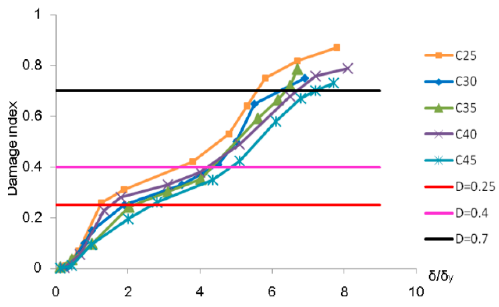
The study simulates the cyclic loading test by altering concrete strength, calculating the displacement item δm/δu and energy item ∫dE/Qy (δu − δy) accordingly. From these results, Equation (5) is used to obtain the damage indices at each stage of force impulsion, which are then compared with the experimental data for MX-1 (of concrete C30).
Using these experimental data, the study separates the process into different stages (see Figure 11), the results of which coincide with the stage partition given by the finite element model. Therefore, the established damage model and damage stage can be considered to be valid.
Then, building on the given damage stage and failure performance in cyclic loading testing, we present a stage-by-stage overview of the structural performance with respect to accumulated damage.
Preliminary development stage (where D = 0–0.25)
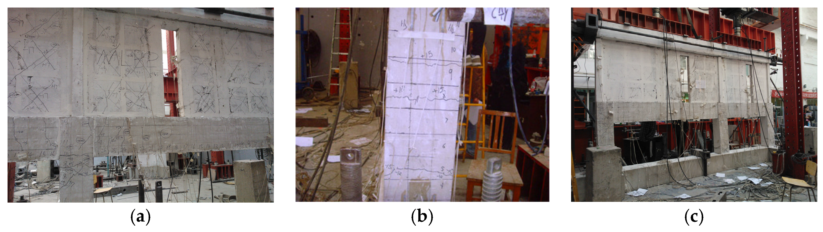
Few tensile cracks are observed at the hole portal and at block joints, which then tend to close up under reversed loading. As the loading continues, minor cracks reach the FS columns, the FS beams, and the structural columns at the portal. These cracks then increase in quantity. In the process, the loading-displacement curve follows a linear variation pattern. In addition, it must be noted that the reinforced embedded steel bears little strain, while the blocks, ribbed beams, and ribbed columns at the upper structure work cooperatively (see Figure 11).
Mid-term development stage (where D = 0.25–0.4)
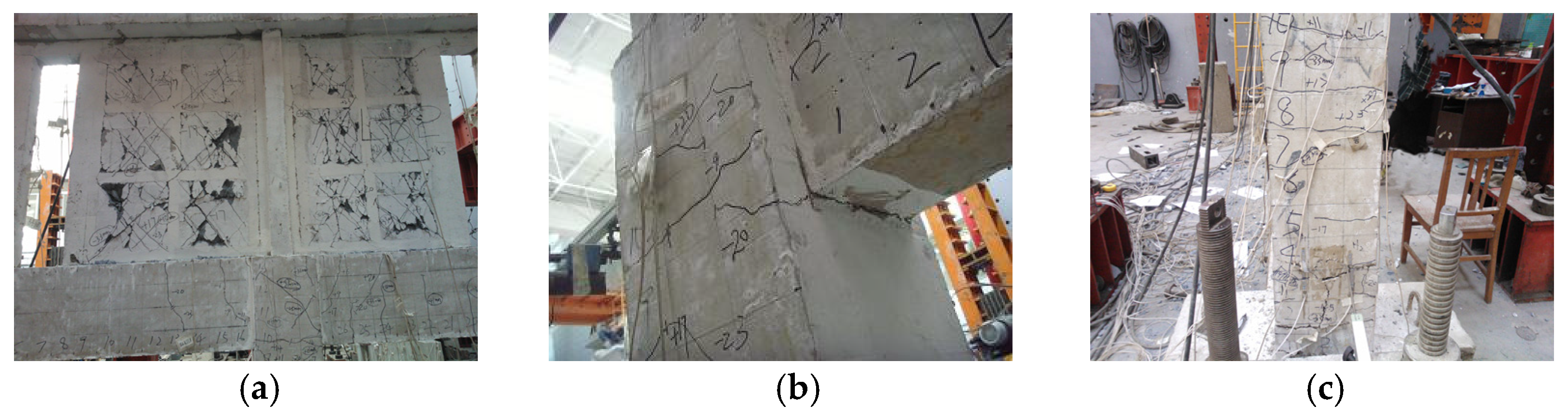
At this stage, visible cracks are apparent in the blocks as tensions are imposed. As the applied loading is transformed into pressure, cracks increase in quantity and then tend to extend across the blocks. In other words, oblique cracks intersect under cyclic loading. As the loading continues, existing cracks begin to extend in length, while oblique cracks continue to be apparent, accompanied by a slight cracking noise. As the blocks exfoliate, a considerable number of oblique cracks stretch further out to the edges of the ribbed beams and ribbed columns. In spite of the damage described above, the overall performance of the blocks remains extraordinary because of the restraint of the grid. New cracks continue to climb towards the FS beams and FS columns, with through-cracks occurring horizontally on the FS columns (see Figure 12). At this point, the hysteretic curve, which begins as a spindle-like curve, then approaches the original point. A pinching effect then occurs. Simultaneously, the stiffness of the specimen continues to deteriorate.
Rapid development Stage (where D = 0.4–0.7)
Severe damage largely deteriorates adhesion at the block–grid interface, which results in visible sliding and exfoliation. The majority of cracks, located at the edges of ribbed beams, cut through the cross-sections of the beams. The concrete at the FS column base cracks, and flexural cracks increase in quantity. Visible cracks develop in the beam-column joints (see Figure 13). At this point, the hysteretic curve envelopes increase in size, which can be interpreted as an increase in energy consumption.
Failure stage (where D > 0.7)
The experiment now reaches an enduring stage, as the paper tightens displacement control. As the displacement amplitude increases, the force bearing capacity of the wall panels decreases. In the meantime, more cracks can be observed at the block–grid interface, and exfoliation occurs on a large scale, which results in a hole opening at the upper wall panel. As loading proceeds, the structural columns at the hole portal bend, while concrete at the edge columns, connected columns, and joint of FS beams and FS columns begins to peel off. At this point, the reinforced steel at the FS column bases begins to buckle, accompanied by a large cracking sound, while sliding takes place at the interface of the upper and lower layer, which then tends to become aggravated. The structure, which has an embedded layer-by-layer design and multiple lines of defence, promises impressive force-bearing performance and the collapse resistance of the edge frame and grid, in spite of the severe exfoliation (see Figure 14). The hysteretic curve shows evident pinching effects. However, the envelope dimensions are still considerably large. Therefore, a conclusion is reached, the structure displays extraordinary performance in terms of energy consumption.
4. Restoration Approach for FSCMR Wall Panel Structure Using the Damage Index
- (1)
- For Di values below 0.25, where the structure has not yet yielded, the cracks that occur are barely noticeable. Therefore, the structure as a whole does not require substantial functional or exterior restoration to ensure its normal operation.
- (2)
- As Di increases from 0.25 to 0.4, the structure yields. Cracks increase in large quantities, blocks peel off and further exfoliate, and the reinforced steel begins to yield. Structural function can only be guaranteed by necessary restoration. In this study, it is suggested that block replacement can mitigate deterioration in bearing capacity. In the case of visible beam/column cracks, a reinforcement approach for reinforced concrete structures shall be applied.
- (3)
- As Di increases into the range from 0.4 to 0.7, the structure has reached the peak of the failure process, where structural deterioration proceeds but slows down. As block exfoliation continues, the cracking and deformation of beams and columns worsens. However, the structure remains restorable, and the approach applied in stage (2) remains effective.
- (4)
- As Di exceeds 0.7, the structure is gravely damaged. Large-scale exfoliation and sliding at the layer interface mean that the structure, though it has yet to collapse, is no longer serviceable. Technically, the structure can be repaired, but the restoration process is hardly economical.
Generally, as Di fluctuates between 0.4 and 0.7, the structure goes through its mid-term, i.e., the stage characterised by the rapid development of accumulative damage. At this point, it is recommended that the force-bearing features of the blocks be leveraged as the first seismic line of defence. Therefore, block replacement can be used to restore the seismic resistance of the wall panel [27]. The move enhances the CMR wall panel structure with energy-efficient blocks, with the features listed below displayed:
- (1)
- The replacement does not generally add to the dead weight or seismic response of the wall panel structure, thereby avoiding problems associated with foundation processing.
- (2)
- The restoration requires no support of the beams or to the floor slab, streamlining the operation process and easing construction procedures.
- (3)
- The material applied can be aerated concrete block, fly-ash block, clay bricks, hollow bricks, etc. Given the accessibility and the applicability of the materials, restoration stands out for its cost efficiency.
- (4)
- Flexibility in the replacement location means that the restoration does not alter the spatial arrangement, which is identical to that existing prior to replacement.
As Di increases from 0.25 to 0.7, any crack or deformation of the beams/columns can be repaired in accordance with the general enhancement procedures for a reinforced concrete structure.
5. Conclusions
In this study on the damage performance of an FSCMR wall panel structure, we reached the following conclusions:
- (1)
- The double-parameter Park–Ang damage model was modified by introducing the displacement factor α into the deformation items, and by considering energy items in the ratio of accumulative hysteretic energy to plastic energy consumption under monotonic loading. Considering different damage evaluation models, the paper calculates damage index curves at each stage of force impulsion. A close comparison helps identify the preferable model for the damage analysis of an FSCMR wall panel structure (namely, the modified double-parameter Park–Ang damage model).
- (2)
- The paper determines the numerical range for the damage index at each stage of accumulative damage, with primary development, mid-term development, rapid development, and failure stages occurring at Di < 0.25, 0.25 < Di < 0.4, 0.4 < Di < 0.7, and D > 0.7, respectively. It must be noted that the experiments conducted contribute to the detailed stage-by-stage description of damage development.
- (3)
- Accordingly, recommendations are made for structure restoration. For Di values below 0.25, no restoration is required. As Di increases into the range from 0.25 to 0.7, it is essential that the structure be enhanced with either block replacements or beam/column reinforcement repairs. As Di increases above 0.7, the structure is beyond repair. We hope that the suggestions provided in this paper will contribute to an improvement of seismic resistance in structures in the future.
Acknowledgments
This research was conducted with the financial support of the National Natural Science Foundation of China (No. 51508009) and Research on Integrated Technology and Comprehensive demonstration of Green Housing (No. 2015BAI03B01).
Author Contributions
Suizi Jia performed the experiment, analyzed the data, and wrote the manuscript; Suizi Jia and Wanlin Cao desiged the experiment; and Suizi Jia and Yuchen Zhang modified the final paper.
Conflicts of Interest
The authors declare no conflict of interest.
References
- Li, B.X.; Xie, H.P.; Deng, J.H.; He, C.R.; Wang, Z. Characteristic analysis of performance and damage of buildings in Wenchuan Earthquake and considerations in aseismic design of buildings. J. Disaster Prev. Mitig. Eng. 2009, 29, 224–230. (In Chinese) [Google Scholar]
- Bai, J.M.; Mary-Beth, D.H.; Gardoni, P. Probabilistic assessment of structural damage due to earthquake for buildings in mid-America. J. Struct. Eng. 2009, 135, 1155–1163. [Google Scholar] [CrossRef]
- Ghorbanie-Asl, M. Performance-Based Seismic Design of Building Structures. Ph.D. Thesis, Carleton University, Ottawa, ON, Canada, 2007. [Google Scholar]
- Zhao, B.; Fabio, T.; Tiziana, R. Field investigation on the performance of building structures during the 12 May 2008 Wenchuan earthquake in China. Eng. Struct. 2009, 31, 1707–1732. [Google Scholar] [CrossRef]
- Liang, X.W.; Li, B.; Li, X.W. Lateral load-carrying capacity of continuous masonry wall supported on RC frame. Adv. Struct. Eng. 2009, 10, 305–317. [Google Scholar] [CrossRef]
- Ahmad, R. Lateral stiffness of concrete shear walls for tall buildings. AIC Struct. J. 2011, 108, 755–765. [Google Scholar]
- Abbas, M. Damage-based design earthquake loads for single-degree-of-freedom inelastic structure. J. Struct. Eng. 2011, 137, 456–467. [Google Scholar]
- Liu, P.; Yao, Q.F. Dynamic reliability analysis of multi-ribbed composite wall based on damage accumulation. J. Vib. Shock 2008, 27, 42–46. (In Chinese) [Google Scholar]
- Xiong, Y.Q.; Yao, Q.F.; Xia, L. Study on damage and energy-dissipation of the fundamental element of multi-ribbed composite wall. J. Shenyang Jianzhu Univ. 2010, 27, 859–865. (In Chinese) [Google Scholar]
- Jia, S.Z.; Yuan, Q. Deteriorating hysteretic parameters and energy dissipation performance of multi-ribbed composite wall structures. J. Huazhong Univ. Sci. Technol. 2013, 41, 32–35. (In Chinese) [Google Scholar]
- GB50011-2010. In Code for Seismic Design of Building; China Architecture and Building Press: Beijing, China, 2010. (In Chinese)
- GB50010-2010. In Code for Concrete Structure Design; China Architecture and Building Press: Beijing, China, 2010. (In Chinese)
- JGJ/T275-2013. In Directive Rules for Muti-Ribbed Wall Structure; China Architecture & Building Press: Beijing, China, 2014. (In Chinese)
- Jia, S.Z.; Cao, W.L.; Yuan, Q. An experimental study of frame-supported multi-ribbed composite walls. Adv. Struct. Eng. 2015, 18, 497–511. [Google Scholar] [CrossRef]
- Jia, S.Z.; Cao, W.L.; Yuan, Q.; Zhang, Y.C. Experimental study on frame-supported multi-ribbed composite walls under low-reversed cyclic loading. Eur. J. Environ. Civ. Eng. 2015, 6, 1–18. [Google Scholar]
- Liu, P.; Yao, Q.F. Dynamic reliability of structures: The example of multi-ribbed composite walls. Struct. Eng. Mech. 2010, 36, 463–479. [Google Scholar] [CrossRef]
- Jia, S.Z.; Cao, W.L.; Zhang, Y.C.; Yuan, Q. Analysis on stiffness ratio at interim layer of frame-supported multi-ribbed lightweight slab. Appl. Sci. 2016, 1. [Google Scholar] [CrossRef]
- Park, Y.; Ang, A.H.; Wen, Y.K. Seismic damage analysis of reinforced concrete buildings. J. Struct. Eng. 1985, 111, 740–757. [Google Scholar] [CrossRef]
- Vamvatsikos, D.; Fragiadakis, M. Incremental dynamic analysis for estimating seismic performance sensitivity and uncertainty. Earthq. Eng. Struct. Dyn. 2010, 39, 141–163. [Google Scholar] [CrossRef]
- Tubaldi, E.; Barbato, M.; Dall′Asta, A. Influence of model parameter uncertainty on seismic transverse response and vulnerability of steel–concrete composite bridges with dual Load path. J. Struct. Eng. 2012, 138, 363–374. [Google Scholar] [CrossRef]
- Yuan, Q.; He, Y.Y. Earthquake Simulation Test on the Multi-Ribbed Composite Wall Supported on Frame; Science Paper Online: Beijing, China, 2014; pp. 1–9. (In Chinese) [Google Scholar]
- Tanaka, H. Effect of Lateral Confining Reinforcement on the Ductile Behavior of Reinforced Concrete Columns. Ph.D. Thesis, University of Canterbury, Christchurch, New Zealand, 1990; pp. 153–164. [Google Scholar]
- Mo, Y.; Wang, S.J. Seismic behavior of RC columns with various tie configurations. J. Struct. Eng. 2000, 126, 1122–1130. [Google Scholar] [CrossRef]
- Roberto, V. Methods to assess the seismic collapse capacity of building structures: State of the art. J. Struct. Eng. 2007, 133, 57–66. [Google Scholar]
- Dimitrios, G.L.; Tsuyoshi, H.; Yuichi, M.; Masayoshi, N. Collapse assessment of steel moment frames based on e-defense full-scale shake table collapse tests. J. Struct. Eng. 2013, 139, 120–132. [Google Scholar]
- Jia, S.Z.; Liu, Y.; Cao, W.L.; Zhou, Z.Y.; Zhang, Y.C. Tests and analysis of the compressive performance of an integrated masonry structure of a Brick-stem-insulating layer. Appl. Sci. 2016, 6, 146. [Google Scholar] [CrossRef]
- Piluso, V.; Montuori, R.; Troisi, M. Innovative structural details in MR-frames for free from damage structures. Mech. Res. Commun. 2014, 58, 146–156. [Google Scholar] [CrossRef]
Figure 1.
Diagram for CMR wall panel structure with energy-efficient blocks.

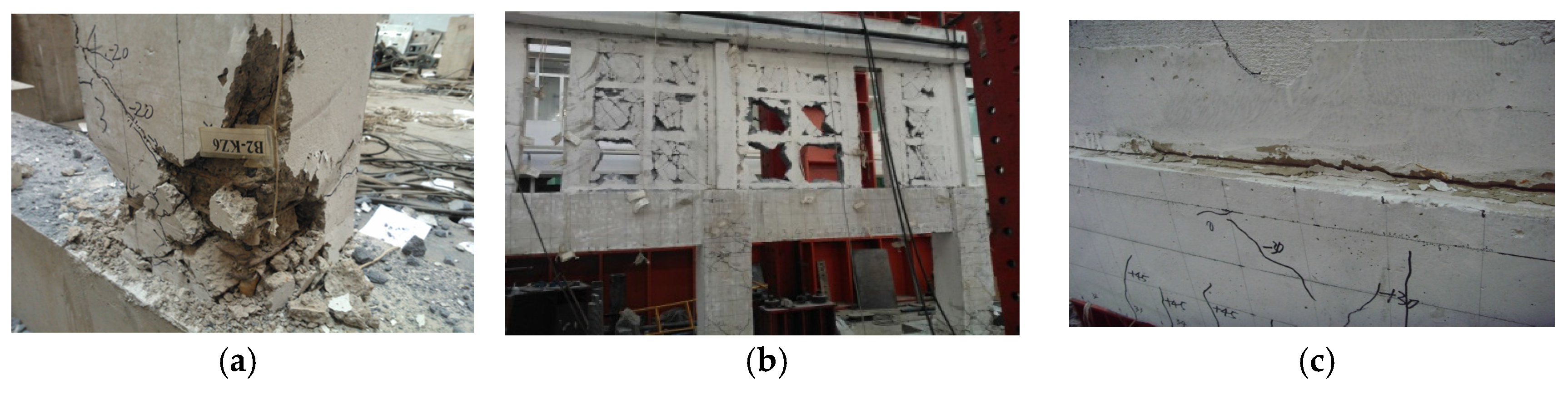
Figure 2.
Residence pilot projects using CMR wall panel structure with energy-efficient blocks. (a) Xing-Guang Hua District in Yin Chuan, the Ningxia Hui Autonomous Region; (b) Geng-xin-street District in Xi'an, Shanxi Province; (c) Zhong-zhou-yu-fu project, in Lankao, Henan Province.
Figure 2.
Residence pilot projects using CMR wall panel structure with energy-efficient blocks. (a) Xing-Guang Hua District in Yin Chuan, the Ningxia Hui Autonomous Region; (b) Geng-xin-street District in Xi'an, Shanxi Province; (c) Zhong-zhou-yu-fu project, in Lankao, Henan Province.
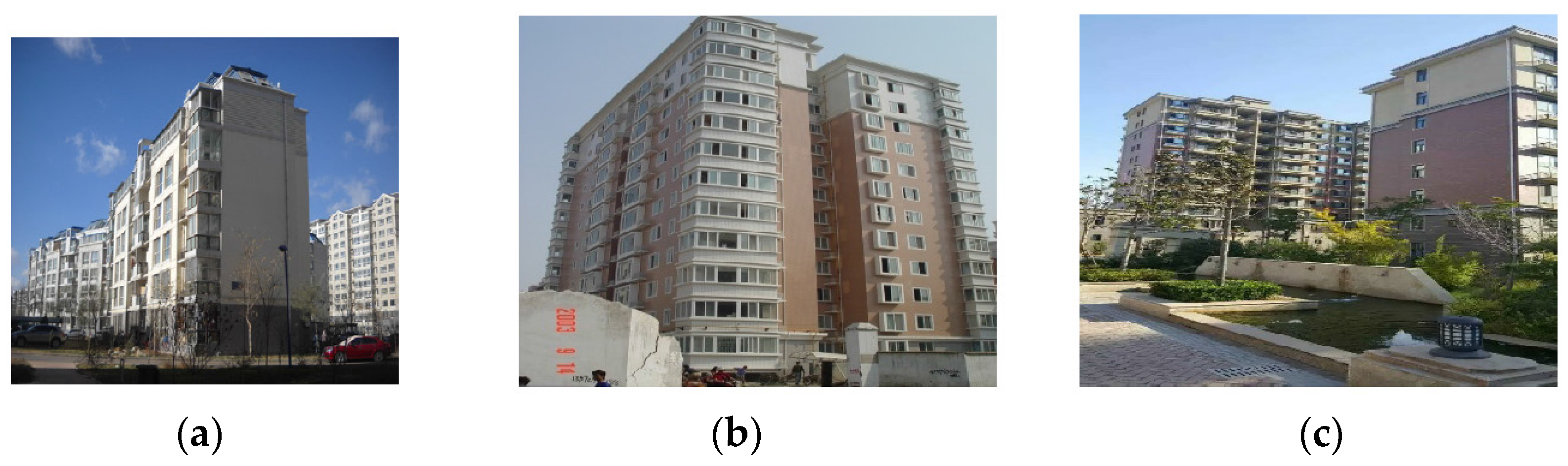
Figure 3.
Multiple seismic lines of defence for CMR wall panel.
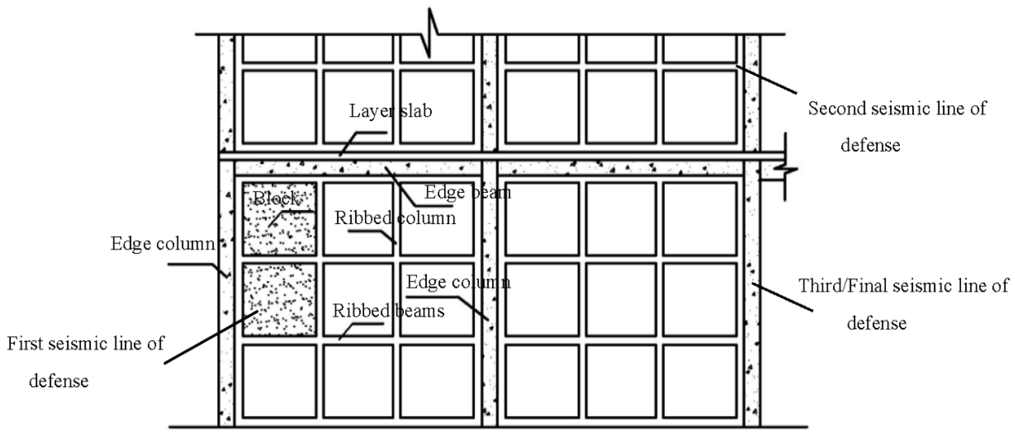
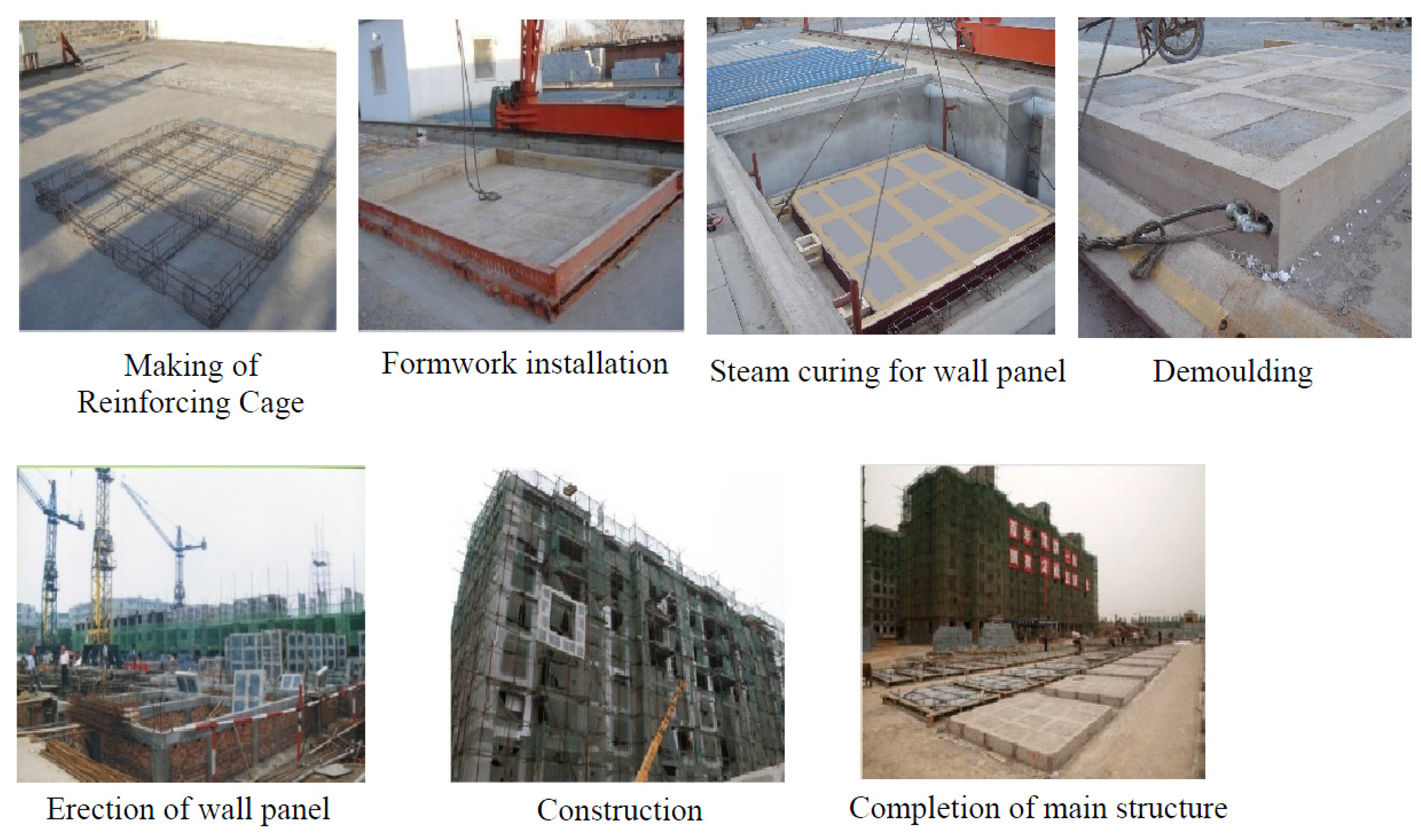
Figure 4.
Production and assembly of CMR wall panel structure with energy-efficient blocks.

Figure 5.
Structural diagram for FSCMR wall panel structures.

Figure 6.
Calculation diagram for plastic energy consumption.

Figure 7.
Relationship curves of damage index and δ/δy.
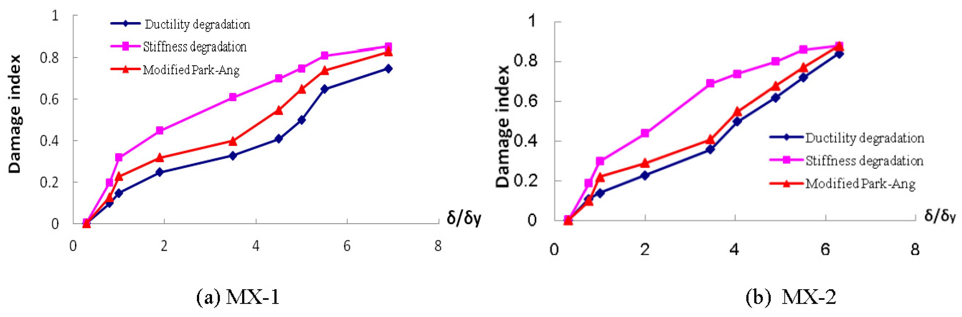
Figure 8.
Comparative diagram of damage indexes between two FSCMR wall panel structures.

Figure 9.
Comparison between calculated values and experimental data (hysteretic curve and skeleton curve).
Figure 9.
Comparison between calculated values and experimental data (hysteretic curve and skeleton curve).

Figure 10.
The MX-1 variation diagram of damage indices for different concrete compositions.

Figure 11.
Preliminary development stage of FSCMR wall panel. (a) Minor cracks on block surface tend to close up under girder restraint. (b) Minor cracks at frame-supported beams. (c) Oblique cracks at either side of the hole along the direction of force impulsion.
Figure 11.
Preliminary development stage of FSCMR wall panel. (a) Minor cracks on block surface tend to close up under girder restraint. (b) Minor cracks at frame-supported beams. (c) Oblique cracks at either side of the hole along the direction of force impulsion.
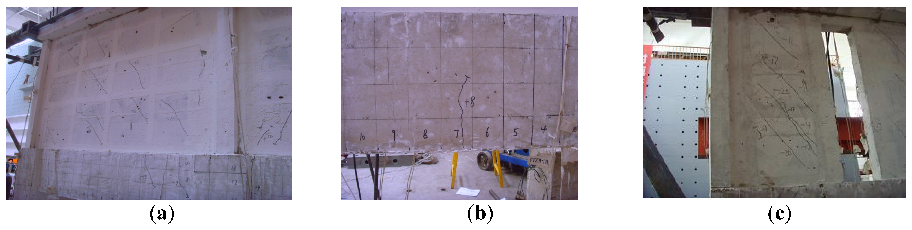
Figure 12.
Mid-term development stage of FSCMR wall panel. (a) As cracks spread out over the specimens, the edge frame is deteriorated in the process. (b) Horizontal cracks intersect on FS column. (c) Block Exfoliation (The upper structure performs fairly well overall thanks to the grid restraint, while cracks on the lower FS structure continue to increase in quantity).

Figure 13.
Rapid development stage of FSCMR wall panel. (a) Visible block exfoliation. Sliding at block-grid interface. (b) Visible cracks at the joints of FS beams and FS columns. (c) Flexural cracks increase at FS columns. Concrete crushing at column base.
Figure 13.
Rapid development stage of FSCMR wall panel. (a) Visible block exfoliation. Sliding at block-grid interface. (b) Visible cracks at the joints of FS beams and FS columns. (c) Flexural cracks increase at FS columns. Concrete crushing at column base.

Figure 14.
Failure stage of the FSCMR wall panel. (a) Convex reinforced steel at the bottom of the FS column Concrete exfoliation; (b) Block crushing due to exfoliation. Deformation of the structural columns at both sides of the hole; (c) Mortar crack and layer sliding.
Figure 14.
Failure stage of the FSCMR wall panel. (a) Convex reinforced steel at the bottom of the FS column Concrete exfoliation; (b) Block crushing due to exfoliation. Deformation of the structural columns at both sides of the hole; (c) Mortar crack and layer sliding.

Table 1.
Dimensions and reinforcement of main components.
| Scale | Component | Dimensions (mm) | Strength Grade of Concrete | Longitudinal Reinforced Steel | Stirrup |
|---|---|---|---|---|---|
| 1/2 | Mudsill | 380 × 400 | C40 | 8Ф20 | Φ6@50 |
| FS Column | 300 × 300 | C30 | 6Ф14 | Φ6@50 | |
| FS Beam | 200 × 400 | C30 | 2Ф14 | Φ6@50 | |
| 2Φ10 | |||||
| 2Ф14 | |||||
| Edge Column | 200 × 200 (100) | C30 | 10Φ6 | Φ6@100 | |
| Connected Column | 200 × 200 (100) | C30 | 12Φ6 | Φ6@100 | |
| Structural Column | 100 × 100 | C30 | 4Φ6 | Φ6@100 | |
| Ribbed Beam, Ribbed Column | 100 × 50 | C30 | 4Φ6 | Φ6@100 | |
| Head Beam | 350 × 300 | C30 | 6Ф20 | Φ6@100 |
Table 2.
Damage index scopes at different failure stages.
| Structure Conditions | Fairly Good | Slightly Damaged | Moderately Damaged | Severely Damaged and Collapsed |
|---|---|---|---|---|
| Park | 0~0.1 | 0.1~0.25 | 0.25~0.4 | 0.4~1 |
| Hindi | 0~0.1 | 0.1~0.2 | 0.2~0.6 | 0.6~1 |
| Ghobarah | 0~0.15 | 0.15~0.3 | 0.3~1 | |
| HU Yuxian | 0~0.15 | 0.2~0.4 | 0.4~1 | |
| NIU Ditao | 0~0.2 | 0.2~0.4 | 0.4~0.65 | 0.65~1 |
| Liu Boquan | 0~0.1 | 0.1~0.3 | 0.3~0.6 | 0.6~1 |
| Wang Guangyuan | 0~0.2 | 0.2~0.4 | 0.4~0.6 | 0.6~1 |
© 2017 by the authors. Licensee MDPI, Basel, Switzerland. This article is an open access article distributed under the terms and conditions of the Creative Commons Attribution (CC BY) license (http://creativecommons.org/licenses/by/4.0/).
Share and Cite
MDPI and ACS Style
Jia, S.; Cao, W.; Zhang, Y. Damage Index Calibration of Frame-Supported Concealed Multi-Ribbed Wall Panels with Energy-Efficient Blocks. Appl. Sci. 2017, 7, 453. https://doi.org/10.3390/app7050453
AMA Style
Jia S, Cao W, Zhang Y. Damage Index Calibration of Frame-Supported Concealed Multi-Ribbed Wall Panels with Energy-Efficient Blocks. Applied Sciences. 2017; 7(5):453. https://doi.org/10.3390/app7050453
Chicago/Turabian StyleJia, Suizi, Wanlin Cao, and Yuchen Zhang. 2017. "Damage Index Calibration of Frame-Supported Concealed Multi-Ribbed Wall Panels with Energy-Efficient Blocks" Applied Sciences 7, no. 5: 453. https://doi.org/10.3390/app7050453
Note that from the first issue of 2016, this journal uses article numbers instead of page numbers. See further details here.