
The Experimental Realization of an Acoustic Cloak in Air with a Meta-Composite Shell


1
Department of Mechanical and Electro-Mechanical Engineering, National Sun Yat-sen University, Kaohsiung 80424, Taiwan
2
Architecture and Building Research Institute, Ministry of Interior, New Taipei City 23143, Taiwan
3
Cepstrum Technology Corporation, Kaohsiung 80245, Taiwan
*
Author to whom correspondence should be addressed.
Appl. Sci. 2017, 7(5), 456; https://doi.org/10.3390/app7050456
Submission received: 10 March 2017
/
Revised: 16 April 2017
/
Accepted: 25 April 2017
/
Published: 29 April 2017
(This article belongs to the Section Acoustics and Vibrations)
Abstract
:Anisotropic cloak shells can be used for the spatial transformation of a space to alter the propagation of acoustic waves by redirecting them along a pre-determined path. This paper outlines the design, fabrication, and experimental analysis of a circular acoustic cloak shell made of meta-composite material for in-air applications. Based on the three-dimensional coordinate transformation, we first designed an anisotropic circle meta-composite cloak shell according to its impedance values. The cloak shell comprises various layered structures with cavities and tubes, respectively, providing acoustic mass and compliance for the provision of anisotropic material properties. Secondly, we conducted numerical and experimental analyses under practice working conditions to demonstrate the efficacy of the acoustic cloak. The structure of the cloak shell, fabricated by three-dimensional printing (3D printing), is experimentally evaluated in a semi-anechoic room with a free-field environment. The simulation and experimental results demonstrate the acoustic cloaking effects in the scattering far field. Besides the scattering field, the sound field measurement results obtained with the region enclosed by the shell also shows the abilities of the cloak shell in altering the direction of wave propagation along a pre-determined path in air.
1. Introduction
In 1968, Veselago [1] proposed the concept of metamaterials possessing properties not found in typical materials in EM waves. Since then, numerous metamaterials have been developed, including negative refraction materials, perfect lenses, and invisibility cloaks (Shelby et al. [2] and Pendry et al. [3,4]). In 2000, Liu et al. [5] used a lead sphere and silicon composite material to construct a resonant sonic material with unique material properties. Lee et al. [6] and Huang et al. [7] reported on a membranous metamaterial structure. Cummer and Schurig [8] developed acoustic cloaks using transformation acoustics. Through the transformation of spatial coordinates, incident sound from all directions can be guided to pass around an acoustic cloak shell. The object within the cloaked region is unaffected by incident acoustic waves and is therefore said to be acoustically cloaked. In 2007, Cummer and Schurig [8] used the exact equivalence of acoustics and EM waves in the construction of two-dimensional (2D) acoustic cloaks. They paved the way for the application of coordinate transformation techniques to provide cloaks for acoustic waves. Three-dimensional acoustic cloaking refers to acoustic scattering, which was developed in 2008 [9], thereby demonstrating the existence of three-dimensional (3D) transformation cloaks. In 2013, Chen et al. [10] expanded the strategy of transformation acoustics from simple cylindrical shapes to general coordinate systems. This was achieved by overcoming the difficulties involved in impedance matching along the boundary of the cloak shell in the background media. Their results have provided a reference by which the material parameters of various acoustic cloaks can be derived. In the field of optics, Andkjær and Sigmund [11] employed topology optimization for designing all-dielectric cloaks in 2011. In 2013, Fujii et al. [12] used a level set-based topology method that provides discrete cloaking configurations with good performance. Otomori et al. [13] proposed a method for the design of an electromagnetic cloak made of ferrite material in 2013. Fujii and Ueta [14] described the topology-optimized carpet cloaks made of dielectric material in 2016. Lan et al. [15] experimentally demonstrated a unidirectional electromagnetic cloak design by topology optimization. They fabricated a Teflon cloaking sample by a precise engraving machine. Urzhumov et al. [16] reported a microwave X-band cloaking device in 2013.
Previous research on acoustic cloaks used the concept of coordinate transformation to develop design parameters for cloak shells. Coordinate transformation alters the material properties of a cloak shell by making them anisotropic with spatially varying mass density and bulk modulus; however, the complexity of such materials has hampered the realization of acoustic cloaks. In recent years, Zhang et al. [17] used a network of acoustic circuit elements to create a cylindrical cloak shell for use in water over a frequency range of 52–64 kHz. They used the same metamaterials for the focusing of ultrasound images with a flat lens [18]. Carpet cloaks in air have also been researched. Popa and Cummer [19] and Zigoneanu et al. [20] used metamaterial structures comprising a periodic arrangement of perforated plastic plates, and used the impedance tube method to measure the transmission properties. Zhu et al. [21] and Popa et al. [22] performed numerical investigations and experiments on 2D triangular acoustic ground carpet cloaks based on perforated plastic plates. Sanchis et al. [23] recently used a genetic algorithm to optimize the ring structure of 3D acoustic cloaks to reduce the scattering of the field in order to make the acoustic cloak workable. In 2013, Andkjær and Sigmund [24] investigated a cloak that conceals an aluminum cylinder acoustically for airborne sound based on a gradient-based topology optimization algorithm. In 2014, Zigoneanu et al. [25] used the concept of carpet cloaks with a metamaterial comprising a structure of perforated plates for the fabrication of a pyramidal device as an acoustic carpet cloak operating at 3 kHz. The pyramidal cloaking device comprised four perforated plate components to enable 3D cloaking.
Theoretical and practical guidelines have been developed for the design of acoustic cloaks in water; however, little work has been completed on the development of cloak shells working in air. Enabling cloaking by the transformation of spatial coordinates (transformation acoustic) requires spatially anisotropic material properties along three coordinate axes. Furthermore, a cloak shell working in air requires a density or bulk modulus of less than unity in some areas of the shell; this, however, is not easy to realize physically. The metamaterials designed for use in water are inapplicable in air. Previous attempts to develop metamaterials aimed at hiding objects submerged in water were unable to provide the anisotropic material density that would be required in air. Even the scattering cancellation techniques proposed by Sanchis et al. [23] are difficult to implement, and the resulting cloak fails when the hidden object is replaced with another object of a different shape. This failure can be attributed to the scattering interaction caused by the incongruity between the new object and the design of the ring structure within the cloak shell.
The present study focused on the design, fabrication, and evaluation of acoustic cloak shells in air. This research involved the physical realization of the acoustic cloak in air by means of the proposed cloak shell designed to spatially vary the impedance values of the cloak shell. In addition to the cloak design, we have also presented a new meta-composite structure material for practical applications. Finally, a real cloak shell was produced by 3D printing and subjected to both numerical and experimental analyses.
2. The Design of the Cloak Shell with a Meta-Composite Shell
2.1. The Design of a Circular Cloak Shell by Three-Dimensional Coordinate Transformation
Acoustic cloaking is an important application in acoustic engineering. Developing the means to control the propagation of sound waves has long been a goal of acoustic engineers. Transformation acoustics [8] have been used in the form of a cloak shell to control the propagation of sound waves by imparting anisotropic material properties. This kind of device can be applied as a noise isolator for residential buildings and schools in the vicinity of highways or airports; however, it requires the ability to affect sounds in the audible frequency range.
This paper presents a novel meta-composite structure based on transformation acoustics, in which the transformation of spatial coordinates squeezes the transformed space into the cloak shell region, as shown in Figure 1a. To produce an acoustic cloak for a three-dimensional object, we applied coordinate transformation in the radial direction, , as well as the vertical direction, , as shown in Figure 1b. The coordinate transformation causes the real domain along the direction to be compressed into the cloak shell region, resulting in the formation of a transformed region inside. The real domain is simultaneously compressed in the vertical direction, , thereby extending the effect of the cloak from 2D to 3D. Thus, the cloaked region in Figure 1b is free from the effects of incident waves, making it an ideal position for the placement of objects requiring cloaking. In the horizontal plane, as suggested by Chen et al. [10], we used the spatial coordinate transformation and governing equation equivalence to determine the material parameters ρ and λ in the transform domain of a 2D coordinate circle cloak as follows:
where and are the mass density and bulk modulus, respectively, relative to the background media; , , and are the position parameters of the coordinate system, as shown in Figure 1b. is a nonnegative real number defining the radial position, lies between 0 to 2π and defines the vertical position. Function is the coordinate transform function in the radial direction to be defined. Further, the vertical space is transformed and compressed along the vertical direction, as shown in Figure 1b. For coordinate transformation in the vertical direction, the transformation function in the vertical direction is selected according to the following: . Here is the scale factor (real constant) in the vertical direction. In accordance with the methods outlined in [10], and using the wave equation equivalence between the coordinate transformed domain and the outside field, the cloak shell material parameters of both radial and vertical directions in the transformed domain can be written as (see the Supplementary Materials):
Following the above method, we designed the 3D acoustic circle cloak shell working in air. Firstly, in the horizontal plane, we selected the transform function f of the cloak shell in the horizontal plane as , where the radial positions are and , and the cloak shell region along the radial direction is . The transform function f leads to , , , and . The above coordinate transformation procedure in the radial direction compresses the region in the real domain within in the horizontal plane into region in the transformed domain. This process makes region in the real domain non-existent in the transformed domain and transforms region into a cloaked region. Objects that one wishes to cloak can be placed inside the cloaked region to protect them from being hit by incoming sound waves. Secondly, in the vertical direction, we randomly selected to obtain the coordinate transformation function in the vertical direction,. Substituting the transformation function into Equations (2a) and (2b) provides the material parameters of the 3D transformed cloak shell as follows:
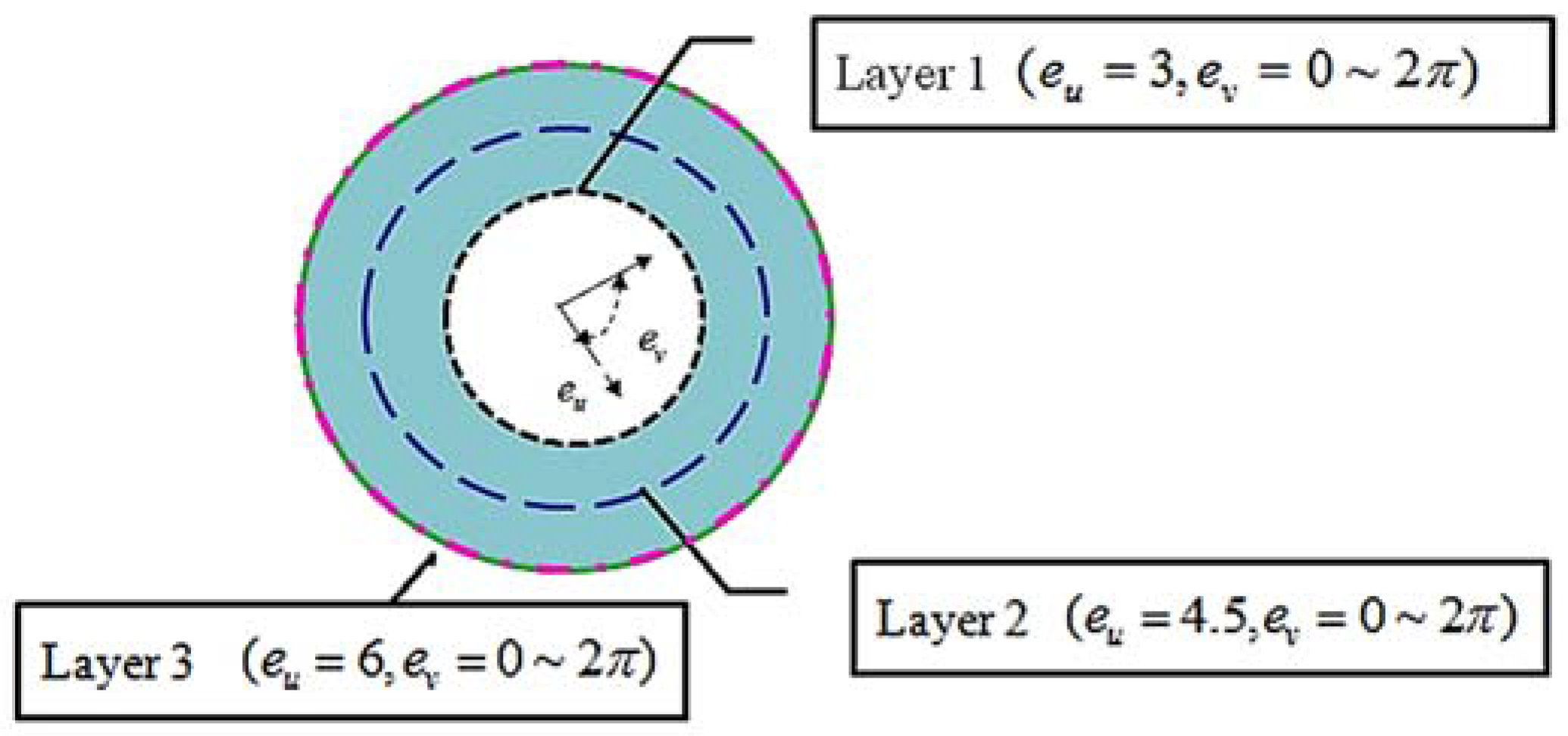
According to the above results, the material properties of the cloak shell along , , and are spatially varying in three directions. The circular acoustic cloak shell is composed of an anisotropic inhomogeneous material. Since the acoustic impedance of the material is the primary factor determining the propagation behavior of waves through the medium; therefore, we use the guiding principle in the design of the cloak shell material. The structural design of the cloak shell is divided into three layers along the radial direction as plotted in Figure 2. The three layers ( = 3, 4.5, and 6; = 0~) construct the cloak shell region; therefore, they will be physically realized by proposing meta-composite structures.
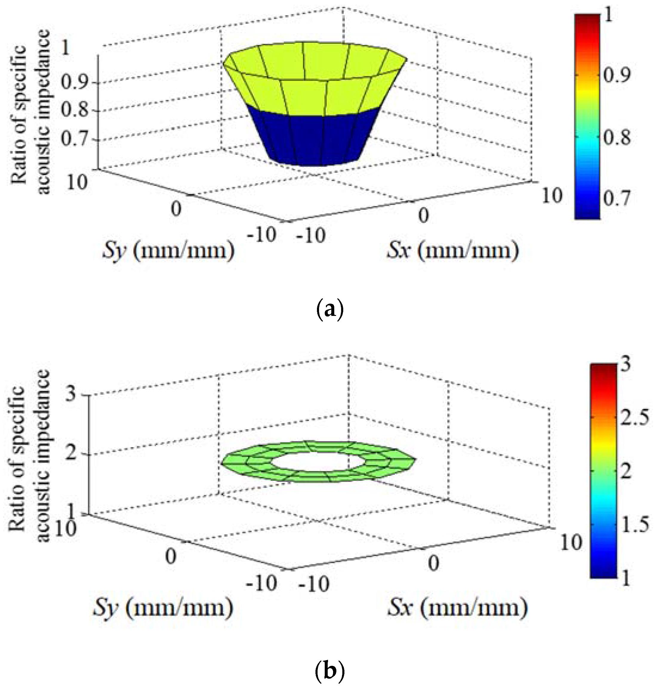
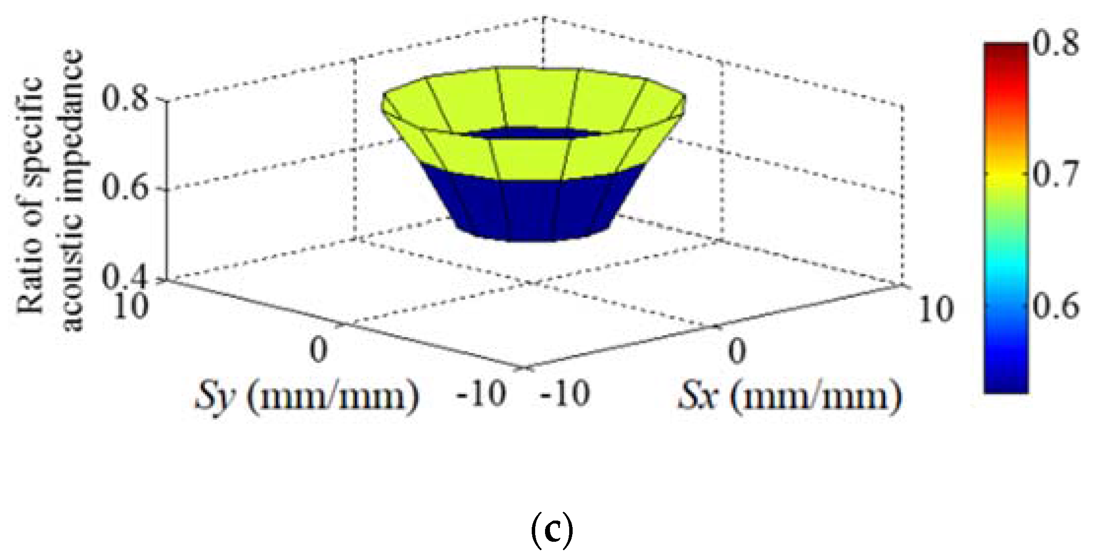
Substituting the spatially varied cloak shell material parameters and in Equations (3a) and (3b) into relationship (the definition of specific acoustic impedance), we can obtain the required ratio of specific acoustic impedance of the cloak shell, , in , and , as shown in Figure 3a–c. The diagram in Figure 3 is plotted according to the relationships between the Cartesian coordinates and the cylindrical coordinate system on the horizontal plane as and , respectively. As shown in Figure 3, the ratio of the specific acoustic impedance values of the cloak shell varies spatially in three different directions. A comparison of the values in Figure 3a to those in Figure 3c shows that, although they exhibit the same distribution, the variation ratios in the , , and directions differ. The impedance values of the cloak shell vary spatially in the and directions, increasing from the innermost to the outermost layer. In the direction, the impedance value is a constant. Furthermore, by substituting the designed material parameters and of the cloak shell obtained in Equation (3) into the phase velocity relationship , the designed phase velocities in the , , and directions within the cloak shell are obtained, as plotted in Figure 4. As shown in Figure 4, varying the velocity along direction while keeping it constant in direction allows for the manipulation of the propagation direction of the acoustic waves in the – plane within the cloak shell. The spatial variations of the phase velocity inside the cloak shell region are related to the coordinate transformation. The coordinate transformation makes the cloak shell become anisotropic and results in the spatial variations of the phase velocity. Through this mechanism, waves inside the cloak shell can be guided along a pre-determined path (as shown in Figure 5, Path A); i.e., the propagation path of the waves can be made to avoid the original transmission path through the transformed region occupied by the cloaked object. In the vertical direction , the effect of the coordinate transformation increases the phase velocity of the acoustic waves, as shown in Figure 4c. Variations in the phase velocity cause the acoustic waves to propagate smoothly upward (as shown in Figure 5, Pre-Determined Path B), thereby producing a cloaked space in the vertical direction. In this way, the cloak shell causes the acoustic waves to propagate along the pre-determined paths and avoid hitting the cloaked object.
2.2. Meta-Composite Structural Design for a Three-Dimensional Circle-Type Cloak Shell
As shown in Figure 3, the specific acoustic impedance values, , vary in some areas of the cloak shell, which necessitates the use of a cloak shell capable of providing these specific impedance values. Here, we propose a meta-composite structure designed to provide different impedance values in the , , and directions through the use of specific structural components. As previously described in Figure 2, the anisotropic cloak shell is active by a three-layer meta-composite structure. Figure 6 explains the composited block elements that form the cloak shell by the layer meta-composite structure. The block elements in the layer are designed according to the spatially anisotropic properties of the cloak shell through impedance design.
Acoustic structural engineering [26,27,28] can be used to develop structural devices, such as tubes and cavities, in order to provide acoustic mass and acoustic compliance, respectively. Thus, the impedance value can be adjusted by altering the configuration of this structural device. As shown in Figure 7a, we assembled block elements with cavities and tubes in three directions, the tubes acting as acoustic mass and the cavity in the center ensuring acoustic compliance. Each block element comprises a single cavity in the center with four tubes in different directions. These block elements provide the acoustic impedance value . In the structure of tube, the physical law governing the motion of air inside the tube [26,28] is , where M is the mass of volume fluid inside the tube. After dividing the cross-sectional area A of the tubes, the motion of air leads to , which can be further expressed as . Using the above, the relationship can be further explained as follows: = = . In the structure of the cavity, the physical laws governing the compression of air being acted on by a force in a cavity [26,28] lead to the following equation: . The value is the acoustic mass or acoustic inertance, is the acoustic compliance. Using the above properties, a block element comprising tubes and cavity structures provides the acoustic impedance value in the respective , , and directions as follows:
The first part, is the acoustic impedance value supplied by the tube structure; the second value, , is the acoustic impedance value supplied by the cavity structure. In Equation (4), , is the circular frequency, is the density of the background medium (air), and c is the wave speed in air. Values A represent the cross section of the tubes and value V is the volume of the cavity. Because tubes connected the cavity, forming as the flanged end in the cavity side, the effective length is the original tube length plus the correction value of the flanged end [27] as shown in Figure 7b.
Equation (4) provides impedance values of the cloak shell in , , and directions. The frequency of the meta-composite structure is set as 1000 Hz, an undistorted frequency for human hearing. Using the relationship in conjunction with the specific cavity dimensions, the cloak shell can be represented using a three-layer metamaterial comprising a structural block element, as shown in Figure 7. Note that is the cross-sectional area of the individual element forming the cloak shell layers, where the element size a of a specific layer in the study is presented in Figure 7b. The design parameters were described in Table 1. Because the metamaterial structure provides acoustic mass and acoustic compliance rather than acoustic resistance, the shell is able to store acoustic energy rather than consume energy and it has a low-loss nature. Figure 8 explains the interior details of the meta-composite material structure, showing the interior details of block elements with rectangular cavities and tubes sliced by a horizontal surface in the – plane and by a vertical surface in the – plane, respectively. Based on the principle of Equation (4), the combination of cavity and tubes of the block element provides the acoustic impedance value in the , , and directions, respectively. The tubes connected the cavity without extending inside the interior of the cavity. In the design, the cloak shell structure element unit is composed of cavity and a pair of tubes series connected in the respective direction. They give the impedance performance as the Helmholtz resonator [29]. Table 1 lists the design parameters of the structure. A total of 144 block elements were used in the cloak shell. The volume of the cavities was set as 27,000 for each layer. The largest size of the cavities was 30 mm, and the wavelength of the design frequency was 343 mm (1000 Hz, c = 343 m/s); therefore, the size of the elements did not exceed 1/10 of the wavelength. The cloak shell structure elements were designed based on the principles of the long wavelength limit [30] and the structure of the cloak shell could then be treated as an effective medium for incident waves. As per the anisotropic nature of the acoustic impedance values in three different directions, the designed block element tube lengths in three directions belonging to the cloak shell are plotted in Figure 9. The spatial variations of the tube length around the circumference of the circle-type shell agree with the required impedance of the cloak shell in Figure 3. Through the combination of the center cavity and different tube lengths in the , , and directions, the proposed meta-composite structure precisely simulates the anisotropic material properties, which provide the shell structure for the 3D coordinate transformation cloak. It also describes the anisotropic material properties of cloak shell can be achieved indirectly through the impedance design.
2.3. A Numerical Simulation of the Cloak Effect in Practice Working Conditions
The cloak shell was subjected to a numerical simulation using ANSYS 14.0 [31] in 3D in accordance with the specifications listed in Table 1. The real object to be cloaked may present with different kinds of geometries and without fully filling the transformed zone. Based on coordinate transformation only in horizontal plane, previous research [17] on 2D is not suitable for the acoustic cloak of a real 3D object. In this study, the numerical experiment was conducted with a circle-type cloak shell with a cylinder object inside the transformed zone of the cloak shell in three dimensions. The meta-composite structure of the cloak shell was modeled precisely without simplification in order to comply with real working conditions. The plane wave was set with a pressure amplitude of 1 Pa incident on a cylinder object (radius = 185 mm, height = 30 mm) concealed in the center, as shown in Figure 10. The diameter of the cloak shell is 840 mm. We selected plastic as the material for the cloak structure to facilitate its fabrication. The 3D geometry of the object and cloak shell was built and enclosed inside a rectangular acoustic domain (5000 mm 2500 mm 100 mm) for the background medium (air). The density and sound speed of air are 1.2 and 343 , respectively. As shown in Figure 11, the sound wave is incident on Surface A propagates forward and interacts with the object. By setting a radiation boundary at Surfaces A and B of the acoustic domain, there is no reflected sound wave in the acoustic domain. Aside from Surfaces A and B, other surfaces of the acoustic domain were assumed to be the free surface.
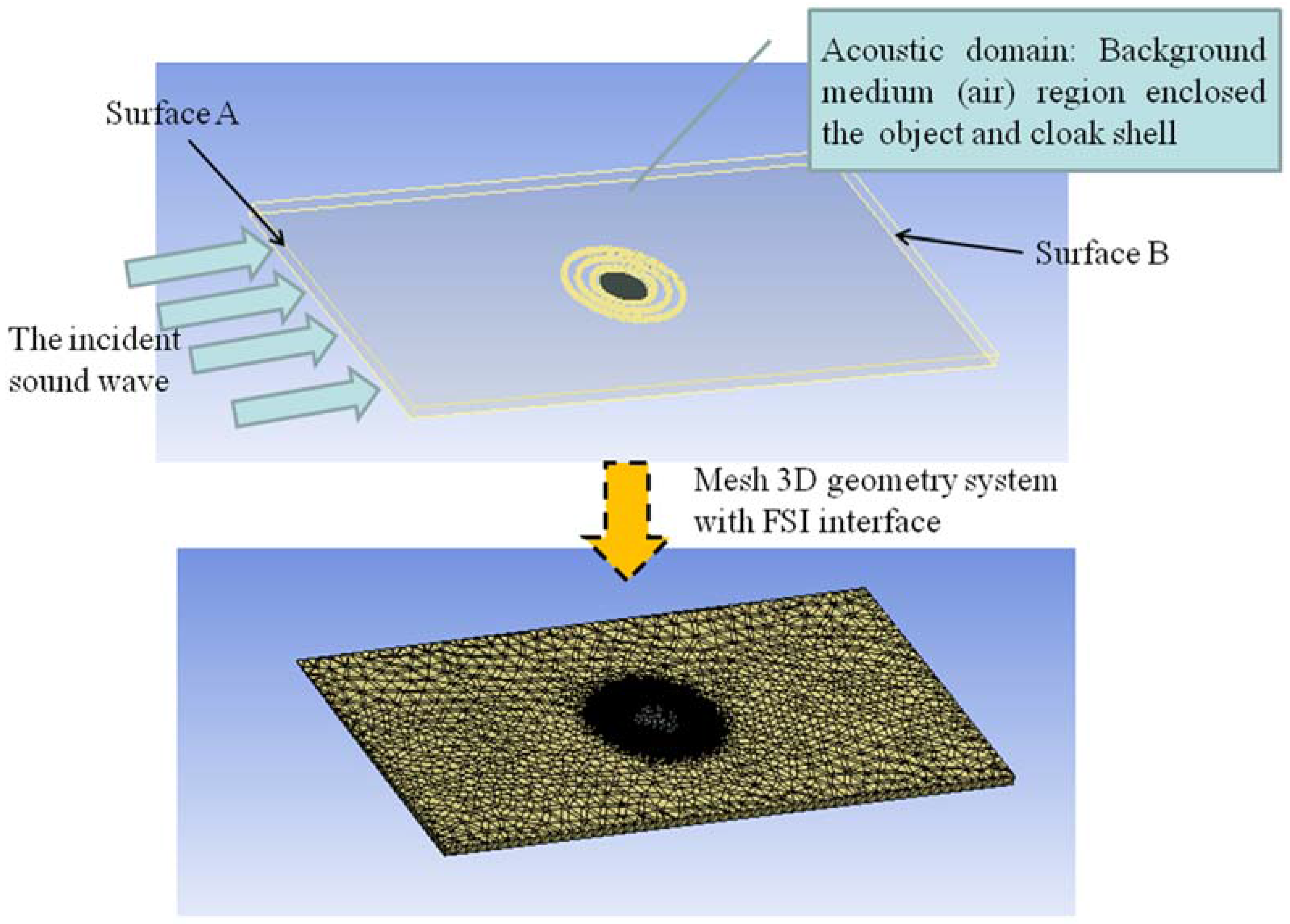
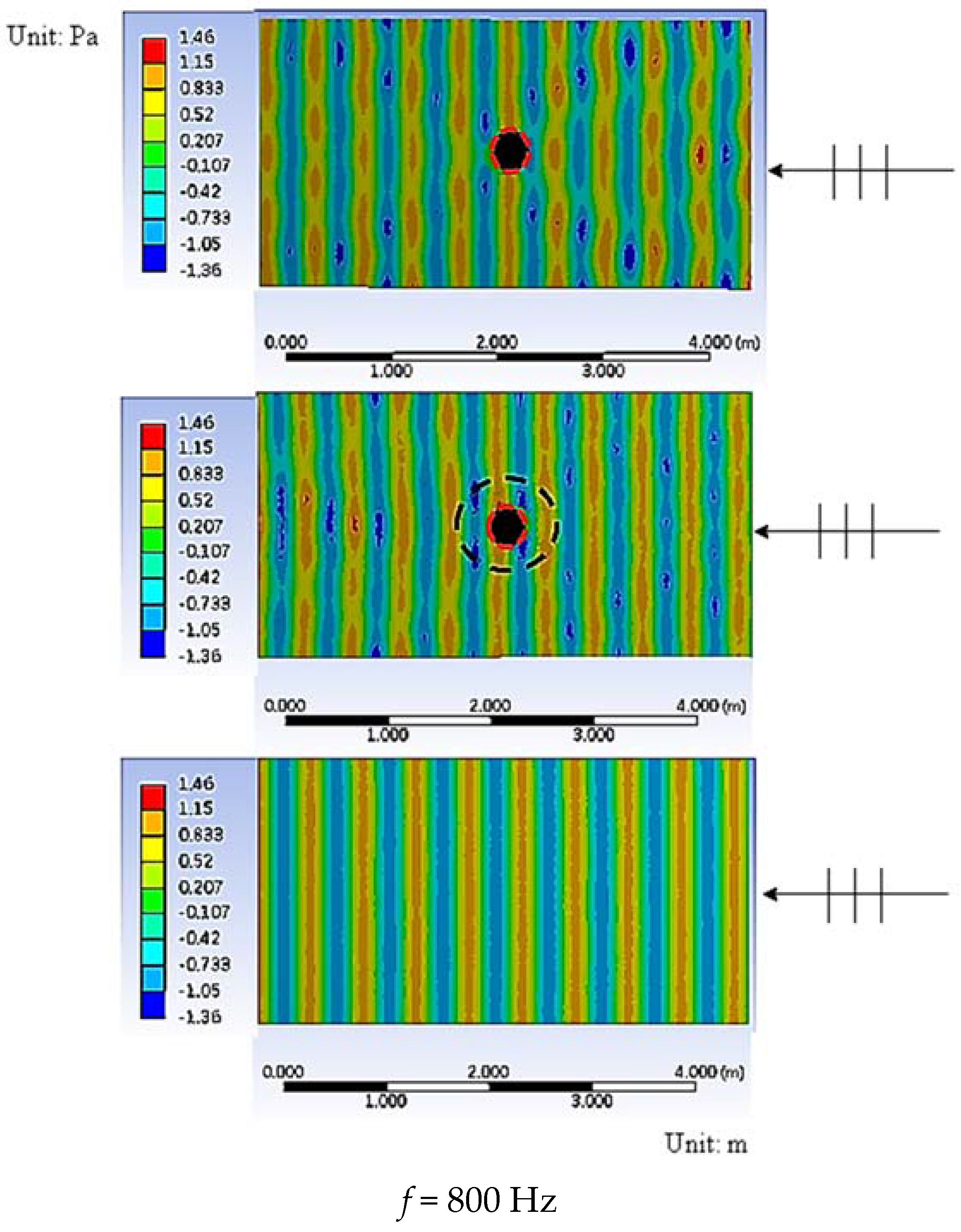
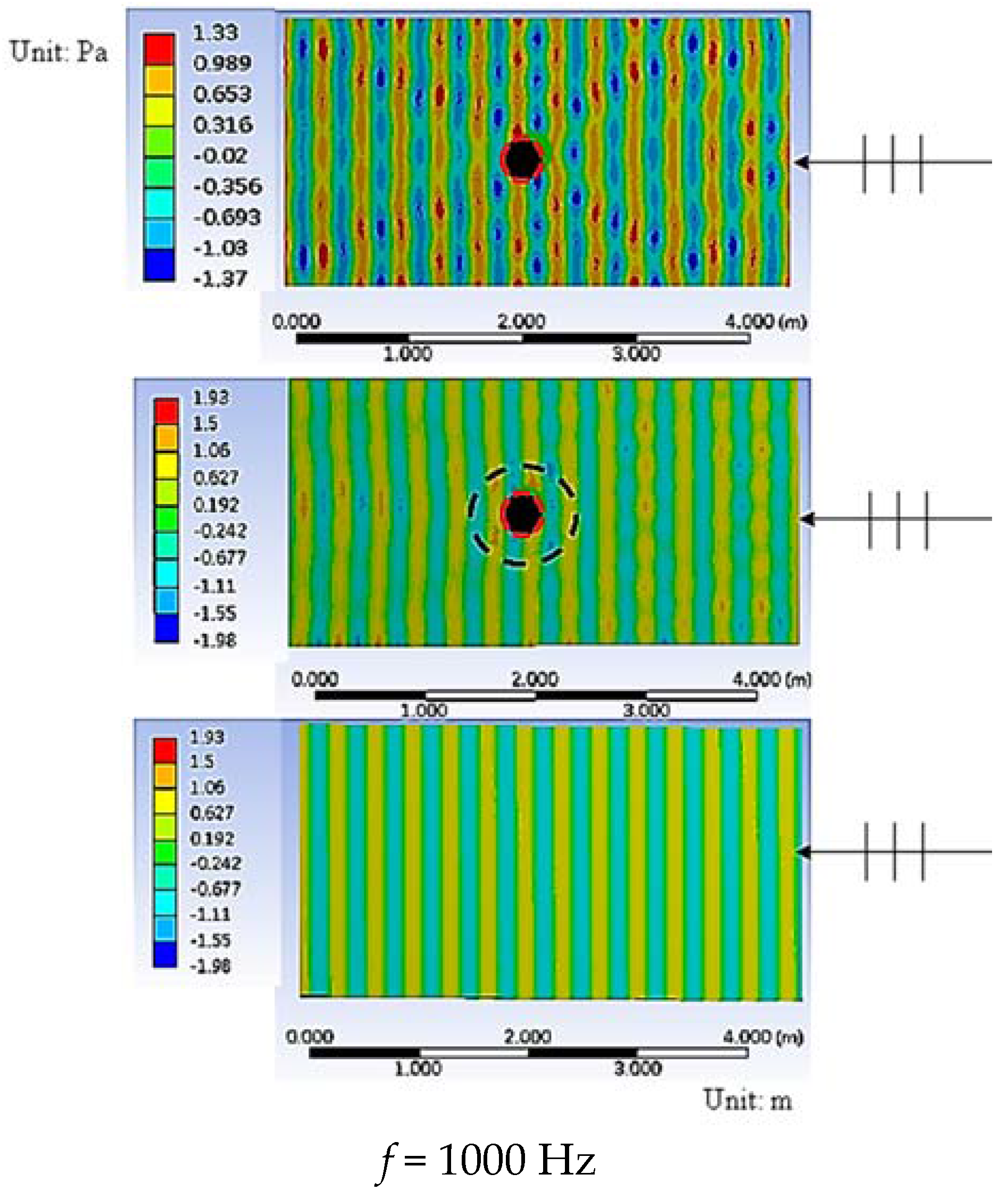
We applied 3D acoustic fluid element (Fluid 221) in the acoustic domain for use in complicated geometry [32]. The 3D geometric model was meshed using a fluid structure interaction (FSI) interface [31] to represent a fluid–structure interaction as plotted in Figure 11. For the sake of accuracy, we used harmonic analysis by the full method to solve all of the system functions directly, rather than using the mode superposition method. The simulation model was solved and evaluated in the post-processing stage, and the pressure field of the whole system was evaluated at the respective frequency. Figure 12, Figure 13 and Figure 14 presents the total wave field of the uncloaked object, cloaked object, and free field (only incident wave) cases at a 1/3 octave frequency of 800–1250 Hz. As can be observed in Figure 12, in the uncloaked object case, incident waves of 800 Hz resulted in obvious wave scattering as compared to the free field. The sound field of uncloaked object case exhibits strong scattering in both the forward and backward directions. However, in the cloaked object case, the wave field at the same frequency also presented a complex disturbance, and the wave cloaking effect was not apparent. Figure 13 shows a comparison of the field patterns between the uncloaked and cloaked object cases at a cloak shell design frequency of 1000 Hz, with the field patterns of the cloaked object clearly showing that the wave passed around the cloak shell and recovered behind the zone of the cloak shell, reconstructing the original wave field. After passing beyond the cloak shell, the wave fronts of the propagating waves were guided back to their original path by the cloak shell, which prevented the production of intense field disturbances outside the cloak shell. The cloaked field exhibited field patterns with less alteration in the overall field than in the uncloaked object case, the results having a similarity to a free field. These results could be attributed to the wave guiding effect of the cloak shell, and these findings verified the effectiveness of the meta-composite structure in acting as a cloak shell. The wave cloak spatially varied the impedance values of the cloak shell, successfully producing the cloak effect by changing the wave phase velocity of and along the horizontal – plane and in the vertical direction, as described in Figure 4.
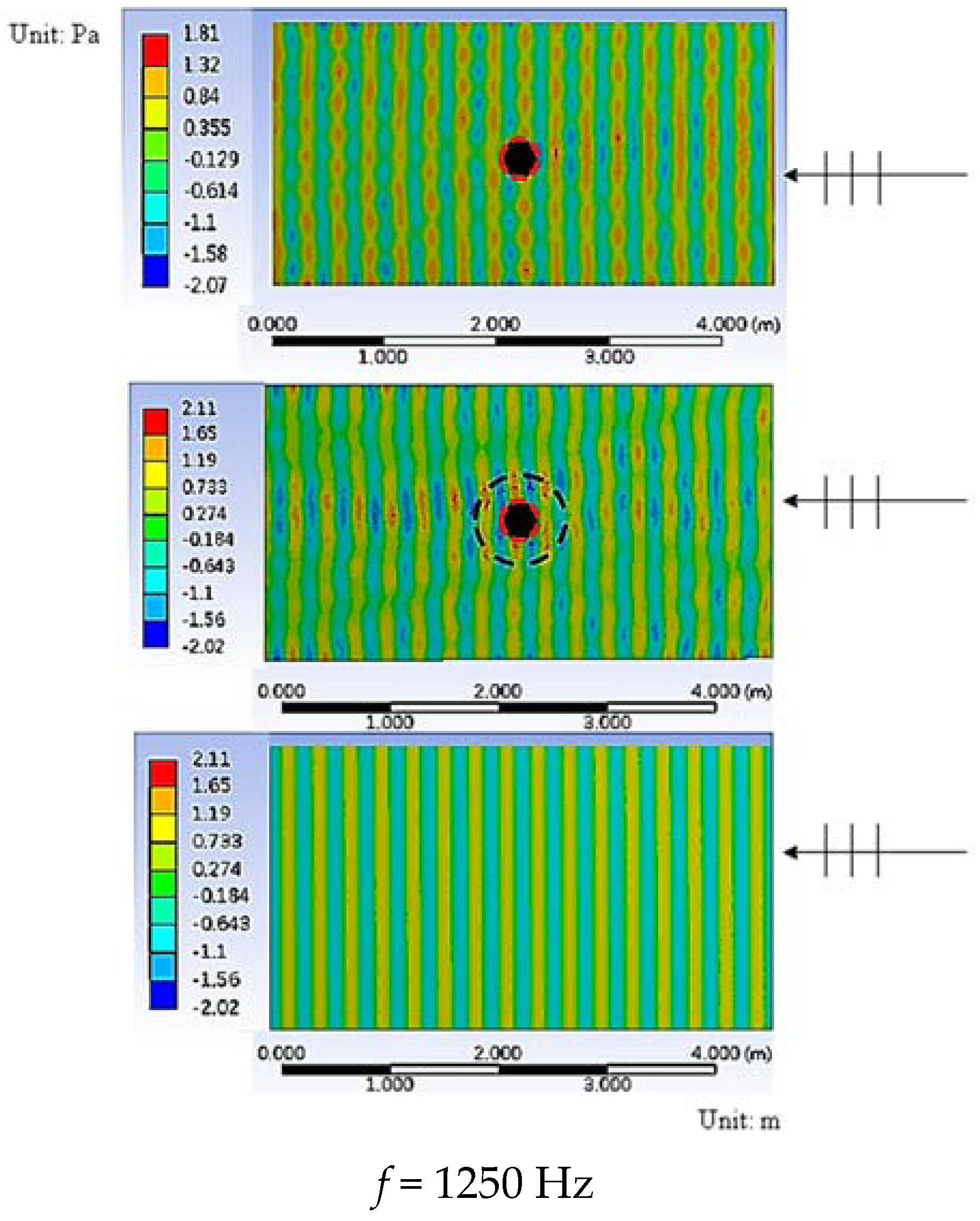
As with the case at 800 Hz, the results at 1250 Hz in Figure 14 show no apparent cloak effect. The cloaked object case, cloak shell concentrated the wave scattering energy and forming strong wave beam in both forward and backward directions. Those strong wave beams break the cloak effect. The field patterns, the wave propagating paths, and the resulting scattering fields of the cloaked and uncloaked cases of the incident wave at 1000 Hz are explained in Figure 15. In the uncloaked case, the incident wave at the center path interacted head on with the cylinder object and produced a typical scattering field in both forward and backward directions. However, the waves in the outer path propagated straight forward unhindered. The scattering field, combining the waves of both paths, was composed of two rectangular high-pressure regions (Region A), which were attributed to scattered energy and wave diffraction. The object in the space shadows the incident wave and forms the Low-Pressure Shadow Region B. This makes obvious pressure disturbance in the sound field and states the uncloaked condition. In the cloaked case, the incoming wave on the center path was guided by the cloak shell and was smoothly restored after passing through the object. These mechanisms avoid the strong scattering effect of the object. Within the unaffected waves in the outer path, the total scattering field of the cloaked case showed flat wave fronts. The pressure field patterns clearly showed more uniform field patterns in both the forward and backward scattering directions in Region C, evidence that the cloak shell guided the waves and created the cloak effect. These results matched the theoretical findings presented in [9]. Our simulation results agreed with the original design concept of transformation acoustics [8] and served to verify the effectiveness of the proposed metamaterial structure of the cloak shell design.
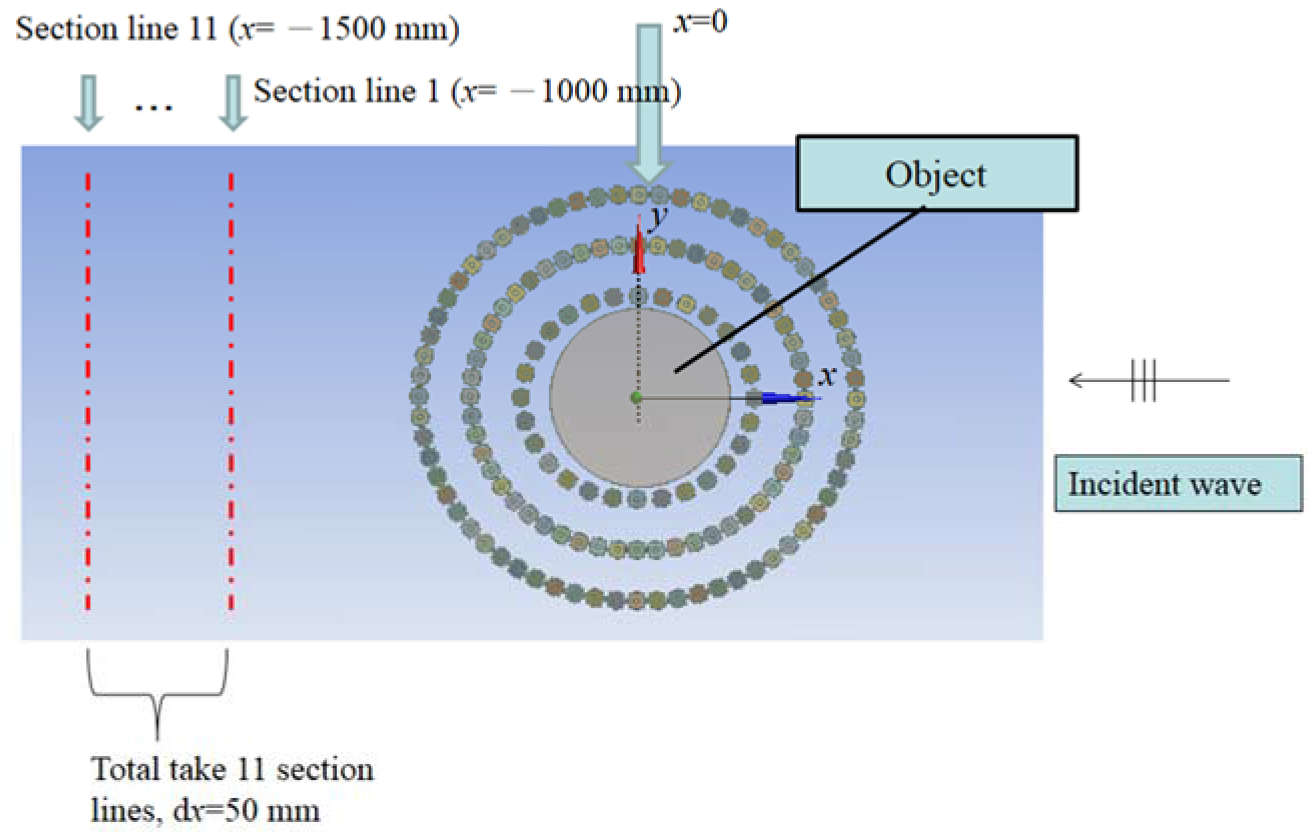
In the investigation of the scattering field, the pressure values with and without the cloak were measured at 11 section lines along the wave fronts in the scattering field. Considering the incident wave length and the linear dimensions of the object, we chose the sound field in the far field [33] for the evaluation of the cloak effect. Taking the far field factor into account, as shown in Figure 16, the positions of the section lines ranged from x = −1000 mm to x = −1500 mm at 50 mm intervals; the width of the evaluated path was 2000 mm in the y-direction. In the z-direction, the positions of the section lines are at half the height (z = 15 mm) of the cloak shell. To evaluate the cloaking performance of the shell, we employed the concept of average visibility, , which is a more convenient metric than the traditional scattering cross section [17]. The definition of is as follows:
where and represent the maximum and the minimum pressure values, respectively, along the individual wave fronts measured at section line j. Parameter N is the total number of wave front section lines included in the analysis, which is positively correlated to the visibility of the object. An increase in the scattering disturbance in the wave field is an indication of greater visibility. If no acoustic waves are present in the environment, then no pressure difference (between the maximum and minimum pressure values) exists in the field and the value of is zero. Figure 17 presents the averaged visibility values obtained in the cloaked and uncloaked object cases from 630 to 1600 Hz. The scattering field was investigated along the 11 path lines in cases involving a cloaked object and an uncloaked object. Clearly, the cloaking ability of the shell structure is quite good at its design frequency at 1000 Hz. The reduction in average visibility values to 20% of that obtained from an uncloaked object. As shown in Figure 17, the results obtained at the frequency of 1000 Hz clearly demonstrated the effectiveness of the acoustic cloak shell. However, in frequency bands lower than 1000 Hz, the decrease of averaged visibility value is not available. Also shown in Figure 17, at higher frequency bands of 1125 Hz to 1600 Hz, the scattering reducing and wave cloak effects of cloaked object case were still unapparent at these frequencies. It seems then, with the present circle-type cloak shell, the meta-composite structure could not provide enough wave-guiding ability at other than the design frequency. In other frequencies, the effects of the wave guiding were not readily apparent. It was therefore concluded that, for the circle-type cloak shell, the most effective frequency of the present meta-composite cloak shell structure was the design frequency of 1000 Hz. Although the cloak shell still provided a working ability at other frequencies, the wave guiding effect was not as effective as at the design frequency. The reason for this could be that the small curvature radius of the circle-type cloak shell created a sharp angle in the wave guiding path and corrupted the cloak effect at other frequencies. Less effective wave guiding ability did not allow for wave guiding at a pre-determined path in a circle-type cloak shell.
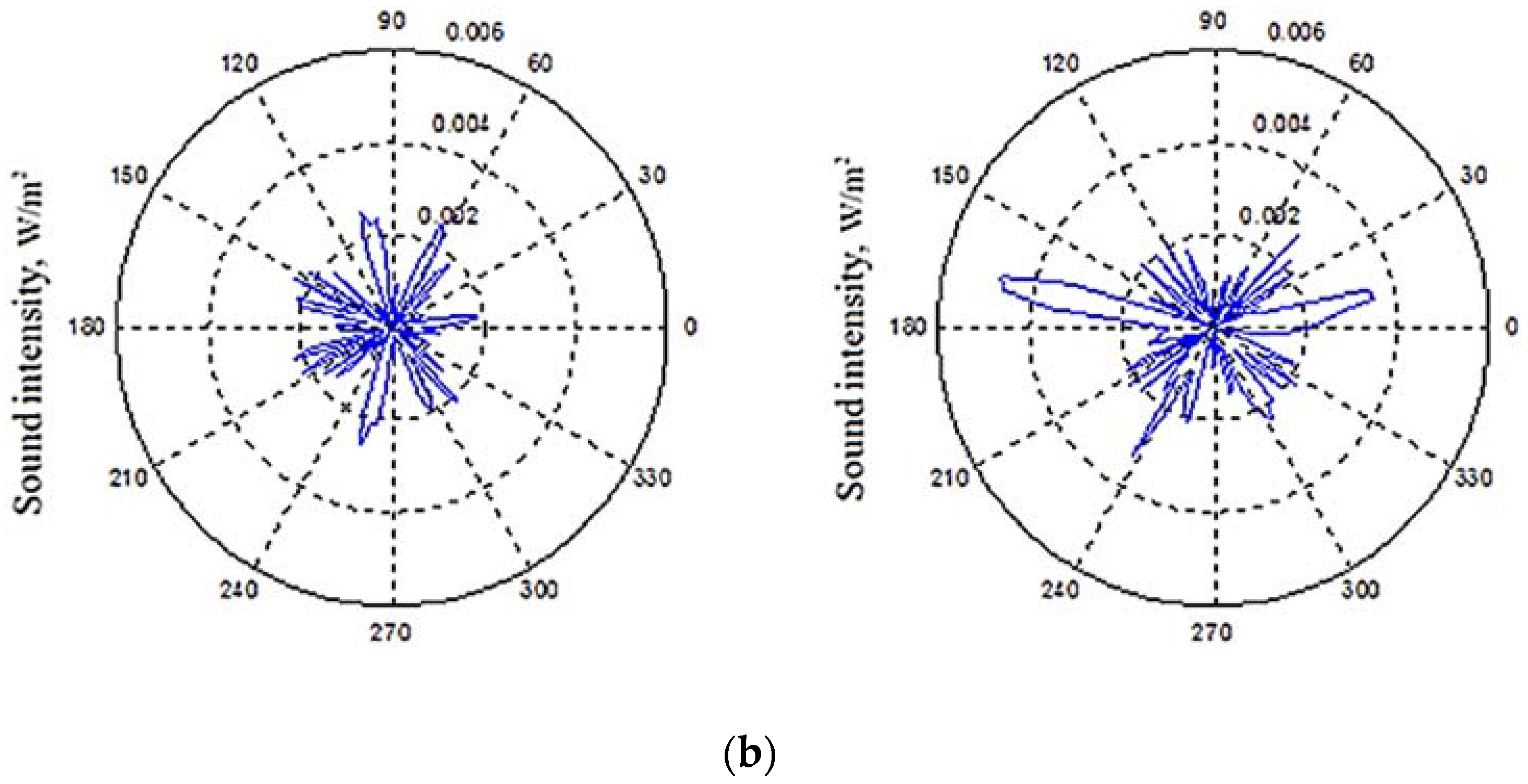
Aside from the total field, we also investigate the scattering sound intensity of cloaked and uncloaked objects. Figure 18 plots the positions of the sampling line, where we sample the circle of sound pressure values around the object at a distance d = 1.2 m from the object in the far field positions. We evaluate the intensity of both the total and the normalized field. The magnitude of the normalized field is processed by substrate the incident field from the total field, resulting in scattering intensity only produced by the object. Figure 19 plots the intensity polar pattern diagram of the total sound field and the normalized field (scattered field of the object) with an incident wave frequency f = 800 Hz. The acoustic wave incident from the polar angle zero interacts with the object in the middle and then passes through at 180 degrees.
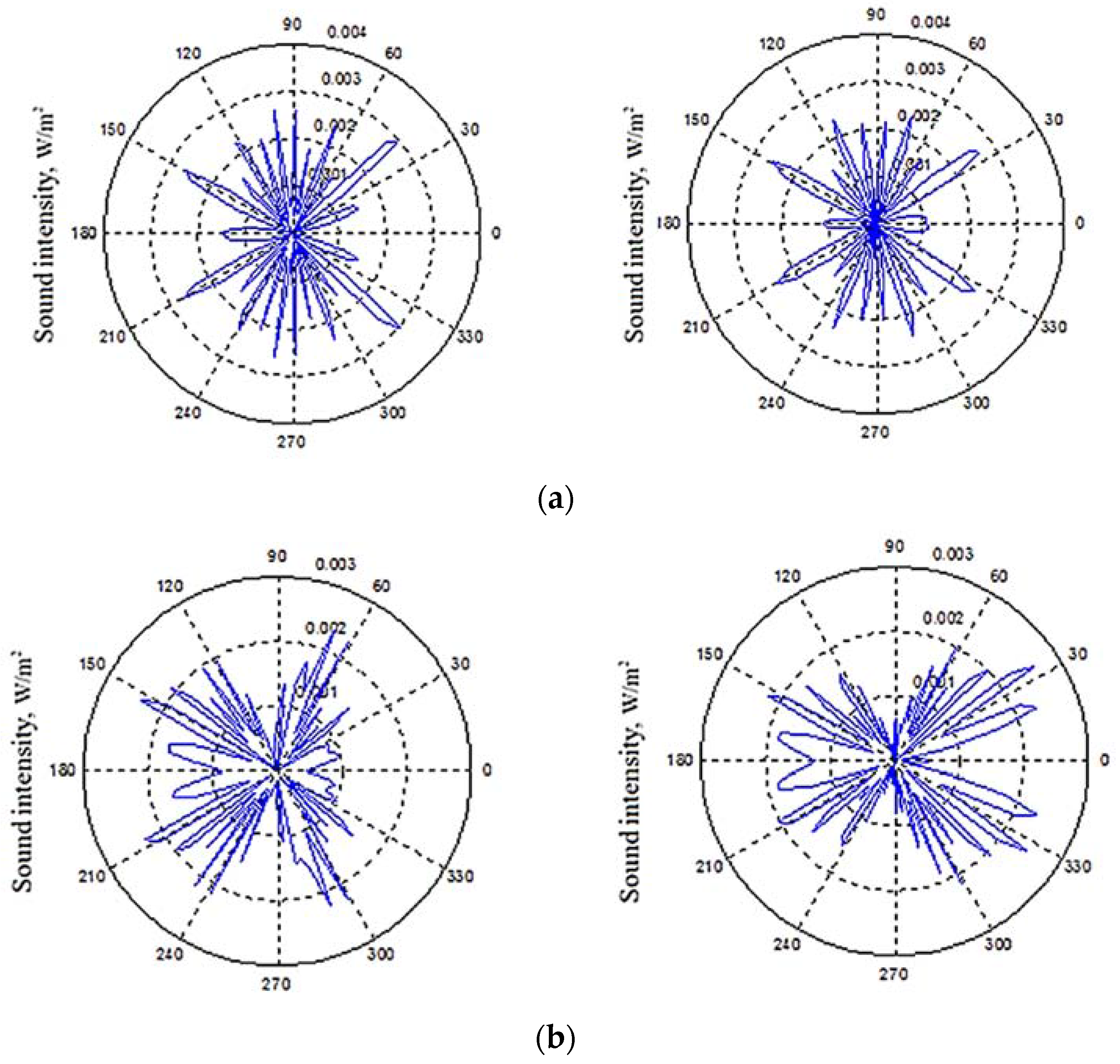
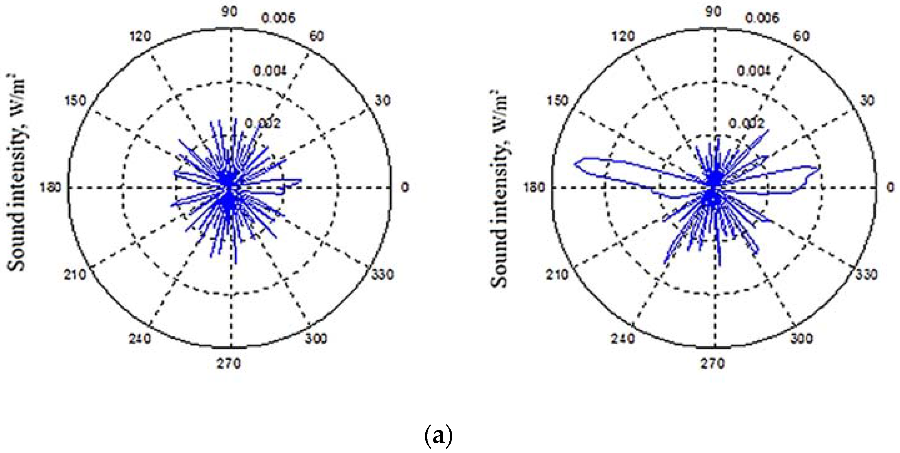
In Figure 19a, the curve of the uncloaked object shows a peak scattering energy in forward directions of 150 and 210 polar degrees and backward directions of 45 and 315 polar degrees. Compared to the polar intensity diagram of the cloaked and uncloaked object cases, the cloaked object case does not exhibit any obvious scattering reduced effect and the scattered intensity amplitude exhibits the same pattern with the uncloaked case in all directions. In the normalized plot (scattered field of object) of Figure 19b, intensity values describe the same results. It can be reasoned that the design working frequency of the meta-composite cloak shell is 1000 Hz, which is an inappropriate incident wave frequency for reducing the cloak abilities. In the incident wave frequency f = 1000 Hz, as shown in Figure 20a, the cloak shell obviously suppresses strong scattering in both forward (150 degrees; 200 degrees) and backward (15 degrees; 345 degrees) directions of the uncloaked object case. This explains a good acoustic cloak effect. In the cloaked object, the peak field disturbances (15 degrees; 345 degrees) are reduced to about one quarter the values of the uncloaked object case. The effect can also be observed in Figure 20b of the normalized results. As described in Figure 20b, the cloak eliminates the strong backward scattering of the uncloaked object and successfully guides the incident wave. In addition, reducing the scattered energy in the all-around directions explains the wave guiding abilities of the cloak shell design. These results consist of the original design concept of the cloak and form the cloak of the object from the incident wave. Looking at f = 1250 Hz in Figure 21a, the uncloaked object results in a sharp scattering beam at 0, 175, and 195 degrees of direction. The cloaked object case in the frequency exhibits strong scattering in both 0 and 180 polar degrees. Figure 21b also describes the same finding. In this incident wave frequency f = 1250 Hz, the cloak is less effective due to a high long wavelength limit. In summary, the polar intensity exhibits the same conclusion as the average visibility and field pattern results, thus verifying the effectiveness of the acoustic wave cloak’s proposed design and acoustic invisibility. The polar patterns of the cloaked object in Figure 21 are asymmetric with respect to the propagating direction of the incident wave. It can be reasoned that, as an incident wave frequency f = 1250 Hz, the cloak is less effective due to the high long wavelength limit. The structural elements of the cloak shell act as individual scatters viewed by incident acoustic waves. They produce complex multi-scattering waves. However, the dimension of the cloaked object in the vertical z-direction is limited, and these complex multi-scattering waves produce complicated out of plane scattering. The out of plane scattering waves in the vertical direction still affect the final sound field. Therefore, the results of cloaked polar intensity patterns are asymmetrical at a high frequency.
Based on the concept of an acoustic scattering cross section [33,34], we define the parameter CSV (cross section value) for qualifying the amount of scattering energy of the object and cloak. The incident wave delivers energy that is , where is the summation of incident wave sound intensity values on surface . The area is the rectangular area normal to the direction of the incident wave as shown in Figure 22a. The scattered energy is evaluated by , where denotes sound intensity values of the scattered wave summarized around the enclosed cylinder surface described in Figure 22a. The surface encloses around the object inside. The parameter CSV is as follows:
The sound pressure values for calculating and are sampled at straight and circular lines in the middle height position of surfaces and , as plotted in Figure 22a. The cross-section values of the uncloaked and cloaked objects from 800 to 1250 Hz are shown in Figure 22b. At 800 Hz, the CSV values show an unapparent difference between both cases. The cloak effect is unavailable at this frequency. This explains the same result as the polar plot shown in Figure 19, but in 1000 Hz, CSV of the cloaked object case is 62% of the uncloaked object case. This provides evidence as to the effectiveness of the cloak design and explains the cloak ability of the cloak shell in a scattered field. The transformed region prevents the incoming wave from interacting directly with the object and reduces the production of strong scattering. In the high frequency of 1250 Hz, the results of the cloaked object case in contrast exhibit higher CSV values than in the uncloaked case. As shown in Figure 21, the strong scattering beam’s forming of the cloak object in this frequency breaks the cloak. This brings the same conclusion in the scattered field CSV results.
3. Experimental Analysis of the Acoustic Cloak
3.1. Fabrication and Experimental Analysis of Meta-Composite Cloak Shell
Experiments were conducted to evaluate the cloak shell design. As in the previous design, the 840 mm diameter of the cloak shell was impracticable for acoustic experiments in a free field; therefore, we adopted the techniques of the acoustic model measurement [35]. The test specimen was scaled down by defining the scaling factor and denoting quantities referring to the model by a prime, for a geometric relationship between the real structure and the scale model of . The time relationship in the scale model is as follows:
Using the same scaling factor for the sound frequencies, the wavelength and the frequency relationships between the original and scaled models can be written, respectively, as and . The experiment was performed in air; therefore, the speed of the acoustic waves of the experimental specimen and the original cloak shell were equivalent. According to the relationship , the equations above can be rewritten as
If the difference in sound level between the two cases is not subject to scaling, from the equivalence of the decrease in energy in the decaying sound field [35], we obtain the following relationship:
where the primed and unprimed systems represent the scale and original propagation condition of the acoustic waves, respectively. Parameter represents the attenuation constant of air and represents the average number of wall reflections associated with a single sound ray each second. Value is the absorption coefficient of air. In this study, the experiments were performed within a semi-anechoic room under free-field conditions. Reflected waves could be disregarded and . To fulfill the experiments with regard to the equivalence of measured sound levels in the scaled specimen and the original cloak shell as written in Equation (12), we used the following field relations between the original and the scale model experimental measurements: , , and . Air was the background medium in both cases, which satisfied the requirement of . The design frequency of the original cloak shell structure was 1000 Hz. To reduce the size of the sample object and shell, we increased the frequency of the incident sound source from 1000 to 2000 Hz. According to the attenuation constant of acoustic waves at different frequencies [35], the attenuation relationship between the frequencies in the experiment and those in the original case was , for a scaling factor of the model of . We scaled down the cloak shell and object according to the scale factor , which resulted in a scaled down cloak shell with a diameter of just 319 mm.
In accordance with the design parameters in Table 1 and scale factor , single block elements were simply duplicated, resulting in a total of 144 block elements. The block elements were scaled down using 3ds Max software prior to fabrication using a 3D printer, as shown in Figure 23a. The real product of the block element components is shown in Figure 23b. Figure 23c presents the assembled block elements of the cloak shell for the experiment.
3.2. Experiment Results: Wave Guiding Effect of the Cloak Shell
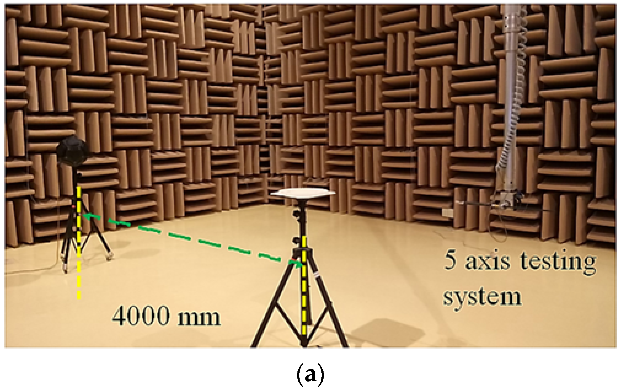
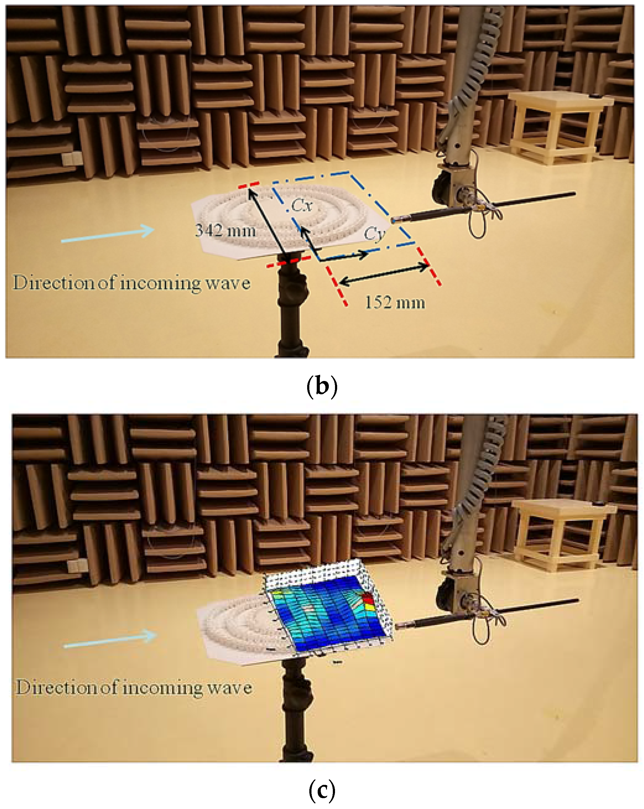
To avoid interference from reflected sound waves and background noise, we performed the experiments in a semi-anechoic room at the Architecture and Building Research Institute, Taiwan. The environment noise rating was NR-5, the volume of the room 516 (10 × 8.6 × 6 m) and the minimum length of the room 6 m, 35 times the wavelength of the sounds being tested (2000 Hz). The low background noise and large testing space created the free-field environment of the acoustic wave. The geometry properties ensured the complete accommodation of the wave period and the free propagation of the wave, thereby ensuring the correctness of the measurement results and the avoidance of unwanted interface noise. To investigate the effects of wave guiding by the cloak shell, we measured the sound pressure field within the zone enclosed by the structure of the cloak shell, as shown in Figure 24. As shown in Figure 24a, we used a B&K Type 4296 omni-directional sound source, which was received using a B&K Type 4190 free-field microphone with a B&K Type 3560E multichannel data acquisition unit. The measurement positions of the microphones were controlled using a 5-axis testing system, with a computer providing a position accuracy of 0.1 mm. The rectangular area in which the measurements were obtained (152 × 342 mm) covered half the cloak shell structure along the Cx–Cy plane, with the microphone positioned just above the cloak shell structure. Measurements were taken in steps of 19 mm in the Cx and Cy directions as shown in Figure 24b. Figure 24c presents the measurement results, indicating the wave propagation behavior inside the half-shell region.
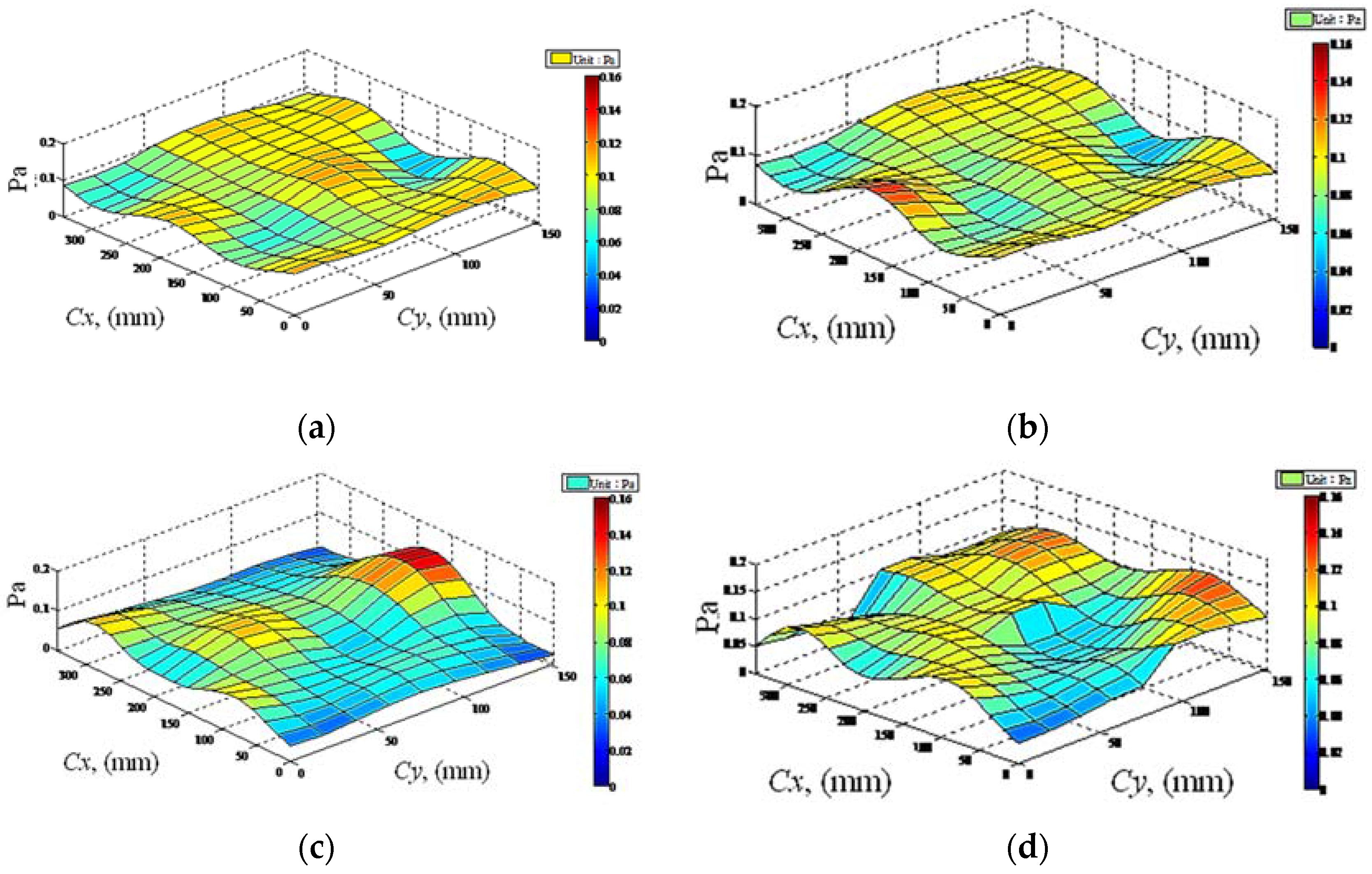
The proposed design utilized the transformation for wave propagation around the cloak shell. It is expected that the anisotropic material properties of the cloak shell cause the direction of wave propagation to change from its original direction to a pre-determined path (see Figure 5). Along the horizontal Cx–Cy plane, the cloak shell will concentrate the acoustic waves at its circumference along the propagation direction of the incoming wave, which kept the wave energy from dissipating and allowed it to continue downstream with minimal scattering. As shown in Figure 25, sound field measurements were performed under four conditions: with neither an object nor a shell and only a specimen supporter in space as a reference sound field, with the object (on specimen supporter), with the cloak shell (on specimen supporter), and with the cloak shell and the object (on specimen supporter). Figure 25a–d present the sound field in these cases, respectively. The sound pressure field, as shown in Figure 25a, is for only the measurement facilities and the specimen supporter, with neither an object nor a cloak shell. This field was taken as the reference sound field for further normalized applications. In the field, some minor disturbances were ascribed to the unavoidable local sound source, which was produced by the local sound field in the measurement positions above the specimen supporter. Figure 25b,c plot the results of the individual measurements of the object and the cloak shell. As shown in Figure 25c, although not obvious, higher pressure values were found around the cloak shell. The highest sound pressure values were obtained in the (Cx = 200, Cy = 140) position, the outermost boundary of the cloak shell, which verified that the waves guided by the cloak shell were restored at the zone. The sound field of the combined object and cloak shell is shown in Figure 25d.
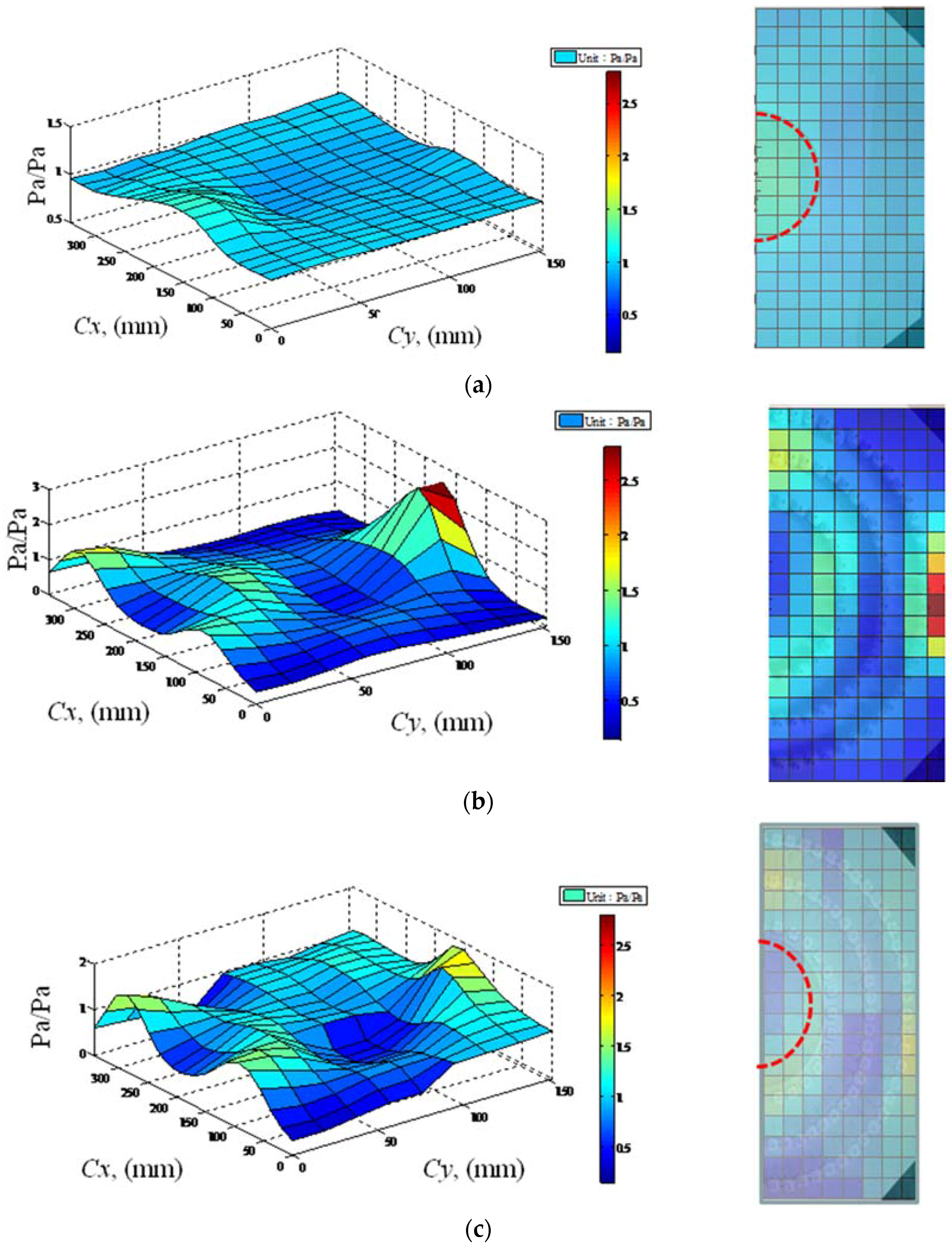
In order to minimize the effect of the local sound source, the sound field of Figure 25a was taken as the reference field in order to normalize the other cases. Figure 26a–c plot the normalized results of the object, the cloak shell, and the object and the cloak shell combined, respectively. We superimpose the normalized sound field results and the real structure position of the cloak shell in one figure and show them in the right column of Figure 26 for readers to more easily understand the behavior. Figure 26a shows the object in the space, and the normalized results are clear evidence of the typical scattering field conforming to the numerical in Figure 13 of the uncloaked object case. The object shadowed the incident wave and formed the shadow region behind the object. The measured low pressure zone between positions Cx = 130~270 mm, Cy = 55~150 mm is the shadow region. The normalized field of the cloak shell in Figure 26b shows the obvious wave guiding effect of the cloak shell. The sound field distribution peak values in the shape of a semicircle were attributed to waves guided around by the cloak shell. Moreover, the observed low-pressure region in the middle position was also because of the wave being guided around the shell and resulting this low-pressure region. The maximum sound pressure peak value in the outer position (Cx = 150~250 mm, Cy = 125~150 mm) was the result of the wave being guided and restored back to the outer region of the cloak shell, and the high normalized field values inside the cloak shell area evidenced that the acoustic waves were guided in a pre-determined path around the circumference of the shell. This mechanism changed the direction of the acoustic waves, which resulted in the successful cloaking of an object. The experimental result showed the changing wave direction within the anisotropic cloak shell. Furthermore, in both the object and cloak shell results shown in Figure 26c, as compared with the object case in Figure 26a, the guiding of the cloak shell forming low normalized field values between Cx = 130~270 mm and Cy = 0~50 mm, which is the position of the object and the transformed region. The low field value in the transformed region avoid the incoming wave interact directly with the object and reduce the production of strong scattering. The results show that the cloak shell reduced the scattering disturbance and created the cloak effect, thereby proving the effectiveness of the cloak shell design.
3.3. Experiment Results: Scattering Field Measurement and Visibility Values
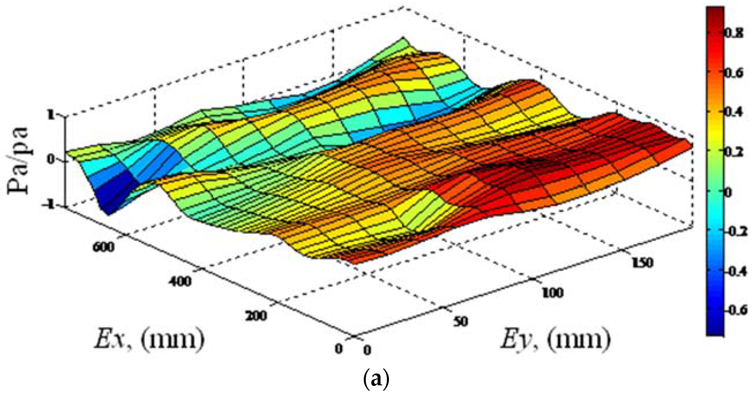
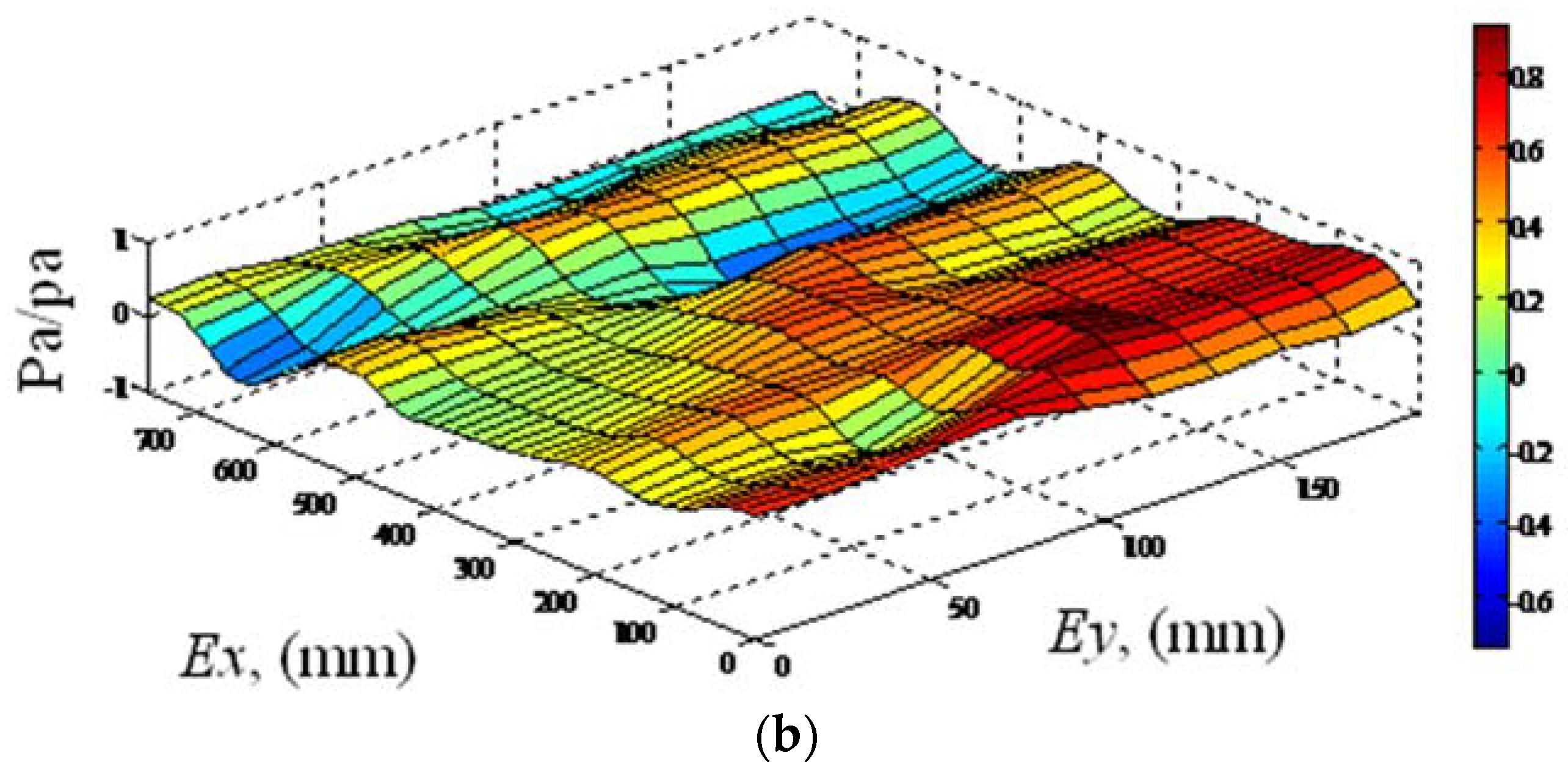
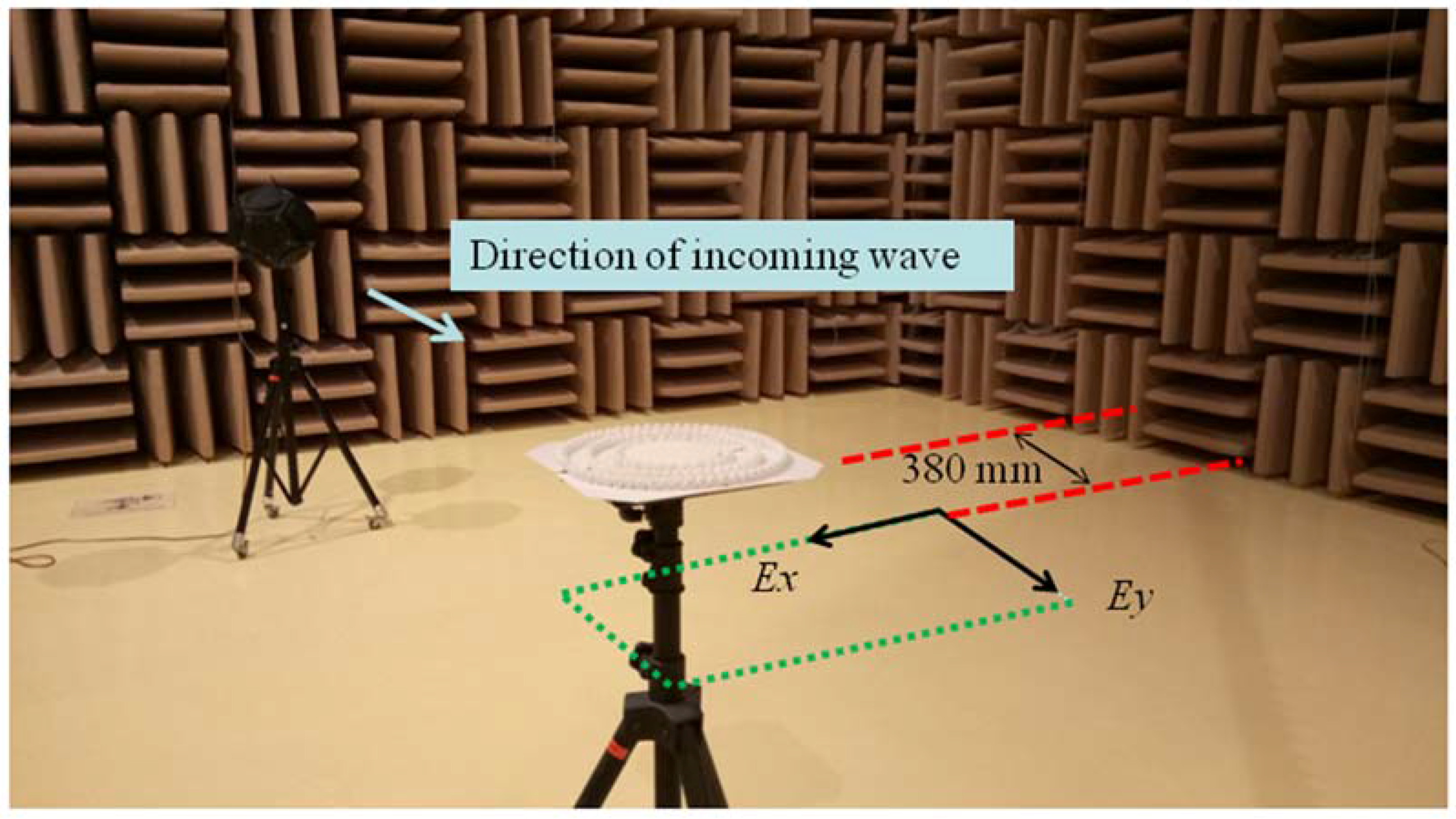
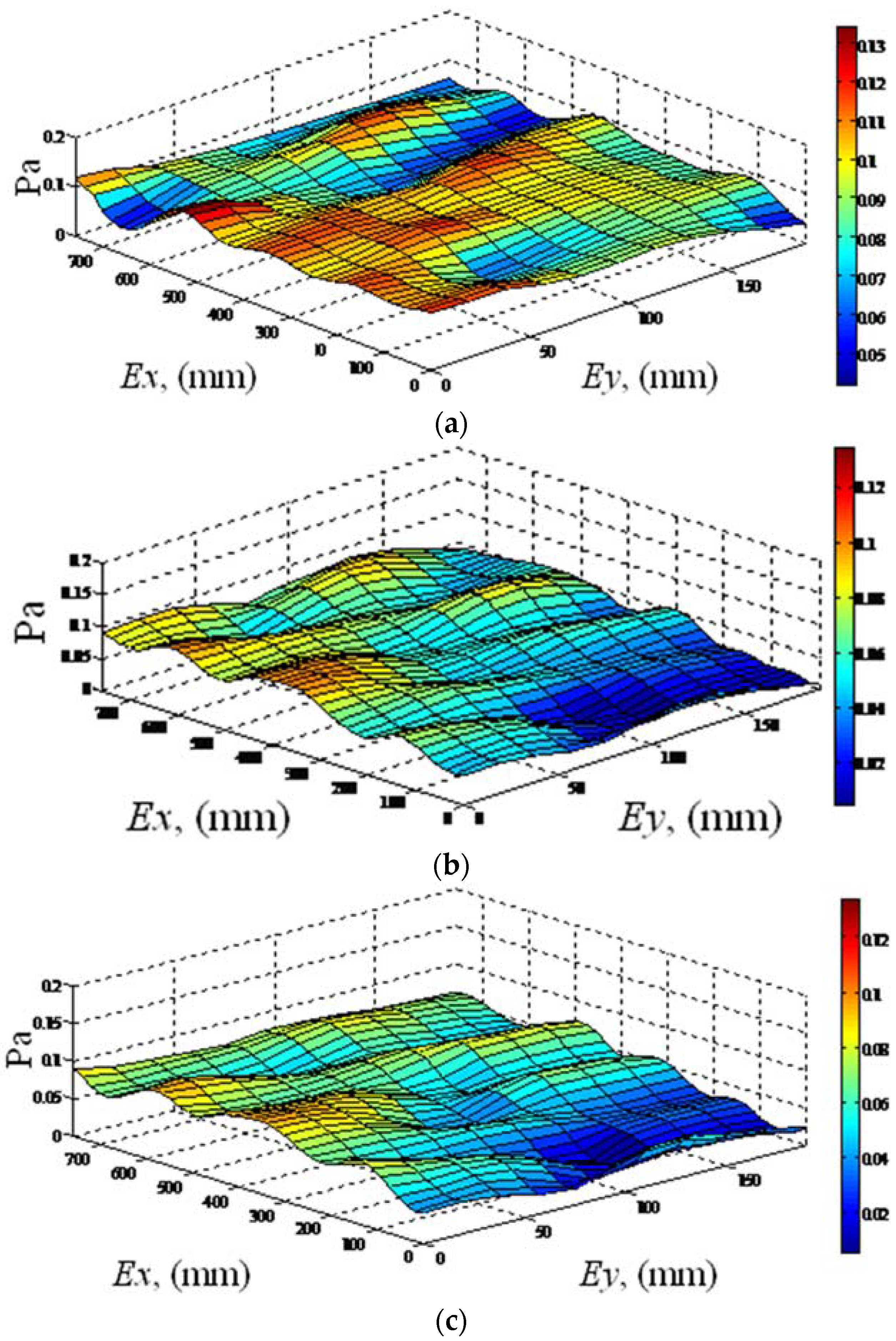
We experimentally investigate the cloak effect in the far field region as a numerical simulation in Section 2.3. The experiment design is consistent with our numerical simulation setup based on the scaling factor of the experiment model defined previously. The sound pressure was measured in the region between Ex = 0~760 mm and Ey = 0~190 mm (dEx = dEy = 19 mm), as shown in Figure 27. The measurement locations of the microphone in the vertical axis are at half the height of the cloak shell. The numbers of field measurement points are 40 points in the Ex direction with 11 lines in the Ey direction. The cloak shell and scattering object were placed on a support unit for the experimental measurements. Measurements were performed for three cases: the incident free field (only specimen supporter in the space), the uncloaked object, and the cloaked object. Figure 28 plots the measured sound field results obtained from the RMS values of the sound pressure. As Figure 28a presents the results associated with the free field. In this case, the sound field presented patterns that were clearly flat field value in the result. Some small disturbances were caused by the support unit used in the experiment. Figure 28b,c presents the results of the uncloaked object and cloaked object cases. These results demonstrated similar sound field patterns, which can be attributed to the real experiment environment limit. Some factors in the real experiment, such as the necessary specimen supporter, the directivity difference of the sound source, and the limited physical dimensions in the vertical direction of real test specimen, will produce errors in the measurement results. In order to reduce the influence of these errors, the sound field of Figure 28a was taken as the reference field in order to normalize the other cases. The normalized sound field presented in Figure 29 were obtained by dividing the free field value for obtaining the real effect of the uncloaked object and cloaked object cases. Thereafter, the results are divided by the reference field (free field in Figure 28a) values to reduce the direction uniformity of the sound source and the unnecessary errors in the experiment. Figure 29a,b plot the normalized field results of the uncloaked and cloaked objects, respectively. The field values over 11 wave-front section lines along the Ey direction in Figure 27 were averaged, and used the Equation (5), then obtained the average visibility value of the cloaked object case 0.32. The average visibility value of the uncloaked object case was 1.01, representing an average visibility ratio of 0.31. The value of the cloaked object was 31% that of the uncloaked object and approximately the value of 20% in the numerical simulation. The finding shows the good cloaking effects and it experimentally verified the effectiveness of the proposed cloak shell design. From the research, the cloak effect of the present study is not available in all frequency ranges. The combination of cloak shell layers with different designs, such as the non-scattering coating layer [36] in the outer surface layer of the cloak shell, may further improve the cloak performance and provide the cloak of acoustic wave in a wide frequency.
4. Conclusions
This paper has reported a meta-composite cloak structure for acoustic circle cloaking. The material properties of the metamaterial used in the structure of the cloak were based on transformation acoustics. The resulting cloaks were subjected to both numerical and experimental analyses, as well as the average visibility of the cloak shell in various frequency bands. In the numerical simulation, the field pattern results showed the cloak availability at the 1000 Hz design frequency of the meta-composite structure, and the visibility results verified the effectiveness of the cloak shell. Aside from the total sound field, the results of the scattered polar intensity patterns and the cross section values of the scattered field exhibit acoustic invisibility of the cloak design. A scaled-down version of the cloak shell structure was also fabricated using a 3D printer to facilitate the evaluation of the acoustic cloaking performance in a semi-anechoic room with a free-field environment. The effectiveness of the acoustic cloak in air was demonstrated at a design frequency of 1000 Hz. The sound field measurements obtained within the region enclosed by the shell also demonstrated the effects of the wave guiding produced by the anisotropic property of the cloak shell. This research has provided a way to apply the anisotropic cloak shell for an acoustic invisibility cloak in air.
Supplementary Materials
The following are available online at https://www.mdpi.com/2076-3417/7/5/456/s1.
Acknowledgments
We are grateful for the advanced research authorization and experimental facilities provided by the Architecture and Building Research Institute, Ministry of Interior, Taiwan.
Author Contributions
Shiuh-Kuang Yang, Jau-Cho Lin, and Jyin-Wen Cheng conceived and designed the study and experiments; Jau-Cho Lin performed the experiments; Shiuh-Kuang Yang and Jau-Cho Lin analyzed the data; Jau-Cho Lin wrote the paper; Shiuh-Kuang Yang, Jau-Cho Lin, and Jyin-Wen Cheng revised the manuscript critically for important intellectual content.
Conflicts of Interest
The authors declare no conflict of interest.
References
- Veselago, V.G. The electrodynamics of substances with simultaneously negative values of ε and μ. Sov. Phys. Uspekhi 1968, 10, 509–514. [Google Scholar] [CrossRef]
- Shelby, R.A.; Smith, D.R.; Schultz, S. Experimental verification of a negative index of refraction. Science 2001, 292, 77–79. [Google Scholar] [CrossRef] [PubMed]
- Pendry, J.B. Negative refraction makes a perfect lens. Phys. Rev. Lett. 2000, 85, 3966–3969. [Google Scholar] [CrossRef] [PubMed]
- Pendry, J.B.; Schurig, D.; Smith, D.R. Controlling electromagnetic fields. Science 2006, 312, 1780–1782. [Google Scholar] [CrossRef] [PubMed]
- Liu, Z.; Zhang, X.; Mao, Y.W.; Zhu, Y.Y.; Yang, Z.Y.; Chan, C.T.; Sheng, P. Locally resonant sonic materials. Science 2000, 289, 1734–1736. [Google Scholar] [CrossRef] [PubMed]
- Lee, S.H.; Park, C.M.; Seo, Y.M.; Wang, Z.G.; Kim, C.K. Acoustic metamaterial with negative density. Phys. Lett. A 2009, 373, 4464–4469. [Google Scholar] [CrossRef]
- Huang, H.H.; Sun, C.T.; Huang, G.L. On the negative effective mass density in acoustic metamaterials. Int. J. Eng. Sci. 2009, 47, 610–617. [Google Scholar] [CrossRef]
- Cummer, S.A.; Schurig, D. One path to acoustic cloak. New J. Phys. 2007, 9, 45. [Google Scholar] [CrossRef]
- Cummer, S.A.; Popa, B.I.; Schurig, D.; Smith, D.R.; Pendry, J.B.; Rahm, M.; Starr, A. Scattering theory derivation of a 3D acoustic cloaking shell. Phys. Rev. Lett. 2008, 100, 024301. [Google Scholar] [CrossRef] [PubMed]
- Chen, T.Y.; Tsai, Y.-L. A derivation for the acoustic material parameters in transformation domains. J. Sound Vib. 2013, 332, 766–779. [Google Scholar] [CrossRef]
- Andkjær, J.; Sigmund, O. Topology optimized low-contrast all-dielectric optical cloak. Appl. Phys. Lett. 2011, 98, 121112. [Google Scholar] [CrossRef]
- Fujii, G.; Watanabe, H.; Yamada, T.; Ueta, T. Level set based topology optimization for optical cloaks. Appl. Phys. Lett. 2013, 102, 251106. [Google Scholar] [CrossRef]
- Otomori, M.; Yamada, T.; Andkjær, J.; Izui, K.; Nishiwaki, S.; Kogiso, N. Level set-based topology optimization for the design of an electromagnetic cloak with ferrite material. IEEE Trans. Magn. 2013, 49, 2081–2084. [Google Scholar] [CrossRef]
- Fujii, G.; Ueta, T. Topology-optimized carpet cloaks based on a level-set boundary expression. Phys. Rev. E 2016, 94, 043301. [Google Scholar] [CrossRef] [PubMed]
- Lan, L.; Sun, F.; Liu, Y.; Ong, C.K.; Ma, Y. Experimentally demonstrated a unidirectional electromagnetic cloak designed by topology optimization. Appl. Phys. Lett. 2013, 103, 121113. [Google Scholar] [CrossRef]
- Urzhumov, Y.; Landy, N.; Driscoll, T.; Basov, D.; Smith, D.R. Thin low-loss dielectric coatings for free-space cloaking. Opt. Lett. 2013, 38, 1606–1608. [Google Scholar] [CrossRef] [PubMed]
- Zhang, S.; Xia, C.; Fang, N. Broadband acoustic cloak for ultrasound waves. Phys. Rev. Lett. 2011, 106, 024301. [Google Scholar] [CrossRef] [PubMed]
- Zhang, S.; Yin, L.; Fang, N. Focusing ultrasound with an acoustic metamaterial network. Phys. Rev. Lett. 2009, 102, 194301. [Google Scholar] [CrossRef] [PubMed]
- Popa, B.-I.; Cummer, S.A. Design and characterization of broadband acoustic composite metamaterials. Phys. Rev. B 2009, 80, 174303. [Google Scholar] [CrossRef]
- Zigoneanu, L.; Popa, B.-I.; Starr, A.F.; Cummer, S.A. Design and measurements of broadband two-dimensional acoustic metamaterial with anisotropic effective mass density. J. Appl. Phys. 2011, 109, 054906. [Google Scholar] [CrossRef]
- Zhu, W.; Ding, C.; Zhao, X. A numerical method for designing acoustic cloak with homogeneous metamaterials. Appl. Phys. Lett. 2010, 97, 131902. [Google Scholar]
- Popa, B.-I.; Zigoneanu, L.; Cummer, S.A. Experimental acoustic ground cloak in air. Phys. Rev. Lett. 2011, 106, 253901. [Google Scholar] [CrossRef] [PubMed]
- Sanchis, L.; García-Chocano, V.M.; Llopis-Pontiveros, R.; Climente, A.; Martínez-Pastor, J.; Cervera, F.; Sánchez-Dehesa, J. Three-dimensional axisymmetric cloak based on the cancellation of acoustic scattering from a sphere. Phys. Rev. Lett. 2013, 110, 124301. [Google Scholar] [CrossRef] [PubMed]
- Andkjær, J.; Sigmund, O. Topology optimized cloak for airborne sound. J. Vib. Acoust. Trans. ASME 2013, 135, 041011. [Google Scholar] [CrossRef]
- Zigoneanu, L.; Popa, B.-I.; Cummer, S.A. Three-dimensional boardband omnidirectional acoustic ground cloak. Nat. Mater. 2014, 13, 352–355. [Google Scholar] [CrossRef] [PubMed]
- Barron, R.F. Industrial Noise Control and Acoustics; Marcel Dekker, Inc.: New York, NY, USA, 2003; pp. 330–405. [Google Scholar]
- Beranek, L.L. Acoustics; American Institute of Physics: New York, NY, USA, 1986; pp. 128–143. [Google Scholar]
- Munjal, M.L. Acoustics of Ducts and Mufflers with Application to Exhaust and Ventilation System Design; John Wiley & Sons, Inc.: New York, NY, USA, 1987; pp. 42–54. [Google Scholar]
- Xu, M.B.; Selamet, A.; Kim, H. Dual Helmholtz resonator. Appl. Acoust. 2010, 71, 822–829. [Google Scholar] [CrossRef]
- Kinsler, L.E.; Frey, A.R.; Coppens, A.B.; Sanders, J.V. Fundamentals of Acoustics; John Wiley & Sons, Inc.: New York, NY, USA, 1999; pp. 128–143. [Google Scholar]
- ANSYS. ANSYS Mechanical APDL Acoustic Analysis Guide; Released 14.0; ANSYS: Canonsburg, PA, USA, 2013. [Google Scholar]
- Howard, C.Q.; Cazzolato, B.S. Acoustic Analyses Using MATLAB and ANSYS; CRC Press: New York, NY, USA, 2014; pp. 22–32. [Google Scholar]
- MacLennan, D.N.; Simmonds, E.J. Fisheries Acoustics, 1st ed.; Chapman & Hall: London, UK, 1992; pp. 20–40. [Google Scholar]
- Banerjee, B. An Introduction to Metamaterials and Waves in Composites, 1st ed.; CRC Press: New York, NY, USA, 2011; pp. 104–110. [Google Scholar]
- Kuttruff, H. Room Acoustics, 3rd ed.; Elsevier Science Publishers Ltd.: New York, NY, USA, 1991; pp. 278–288. [Google Scholar]
- Bobrovnitskii, Y.I. A Nonscattering Coating for a Cylinder. Acoust. Phys. 2008, 54, 879–889. [Google Scholar] [CrossRef]
Figure 1.
Design of circle cloak using transformation acoustics: (a) after coordinate transformation, Region B no longer exists in the transformed domain, thereby making the object within inaccessible to incident waves. This makes the material properties of the cloak shell (Region A) anisotropic and inhomogeneous. (b) Geometric transformation in the vertical direction, , wherein the space in Region C no longer exists in the transformed domain. This operation essentially converts the space within the transformed domain into the equivalent of a thin plate in order to achieve acoustic invisibility for the three-dimensional object.
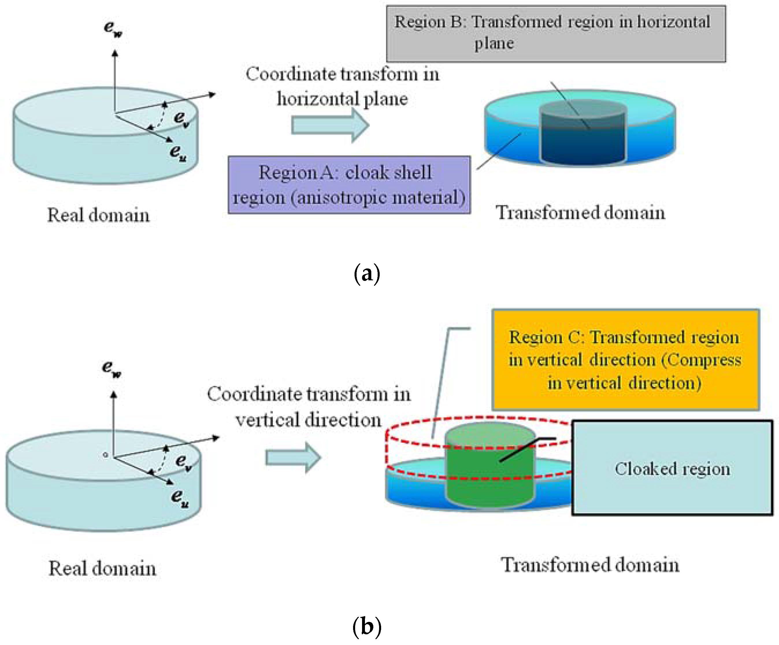
Figure 2.
The cloak shell region is divided into three structural layers. The three layers ( = 3, 4.5, and 6; = 0~) represent the cloak shell region with anisotropic material properties.
Figure 2.
The cloak shell region is divided into three structural layers. The three layers ( = 3, 4.5, and 6; = 0~) represent the cloak shell region with anisotropic material properties.

Figure 3.
The required ratio of specific acoustic impedance value of the cloak shell (relative to the background specific acoustic impedance value): (a) cloak shell region in direction; (b) in the direction; (c) in the direction.
Figure 3.
The required ratio of specific acoustic impedance value of the cloak shell (relative to the background specific acoustic impedance value): (a) cloak shell region in direction; (b) in the direction; (c) in the direction.


Figure 4.
Designed variation in wave phase velocity (relative to background) inside the cloak shell: (a) in the direction of the cloak shell region; (b) in the direction; (c) in the direction. The direction of incoming waves can be guided by altering the wave phase speed using the anisotropic material properties of the cloak shell.
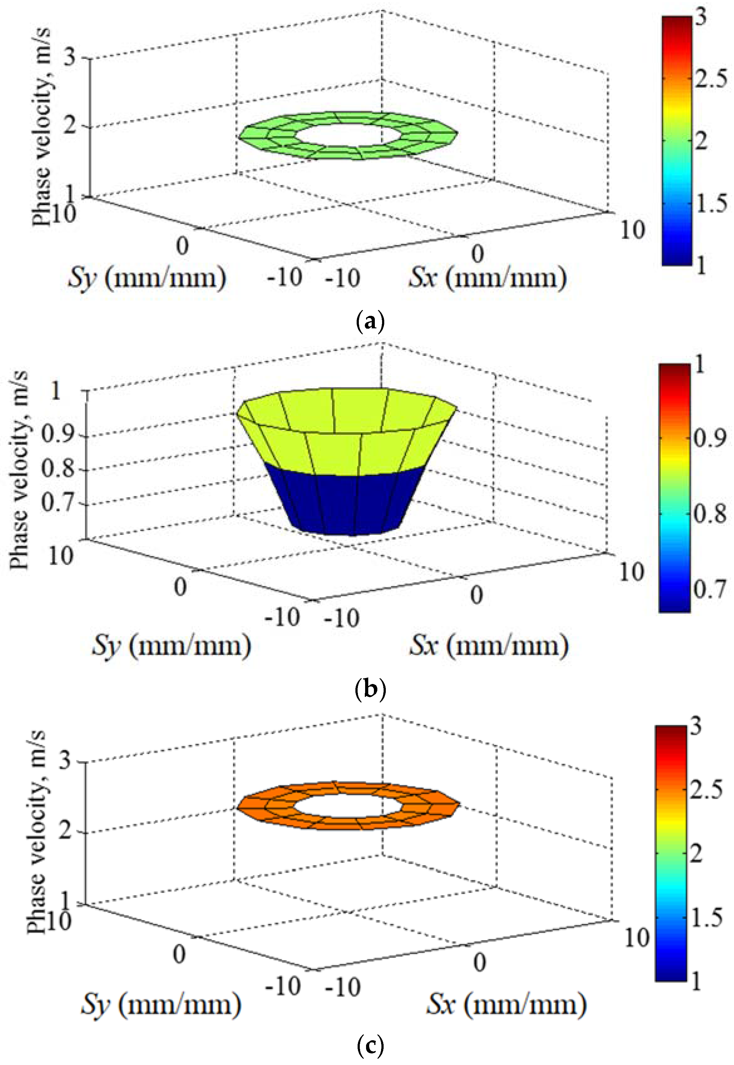
Figure 5.
Pre-determined path for wave propagation around the cloak shell. The anisotropic material properties of the cloak shell cause the direction of wave propagation to change from its original direction to a pre-determined path.
Figure 5.
Pre-determined path for wave propagation around the cloak shell. The anisotropic material properties of the cloak shell cause the direction of wave propagation to change from its original direction to a pre-determined path.
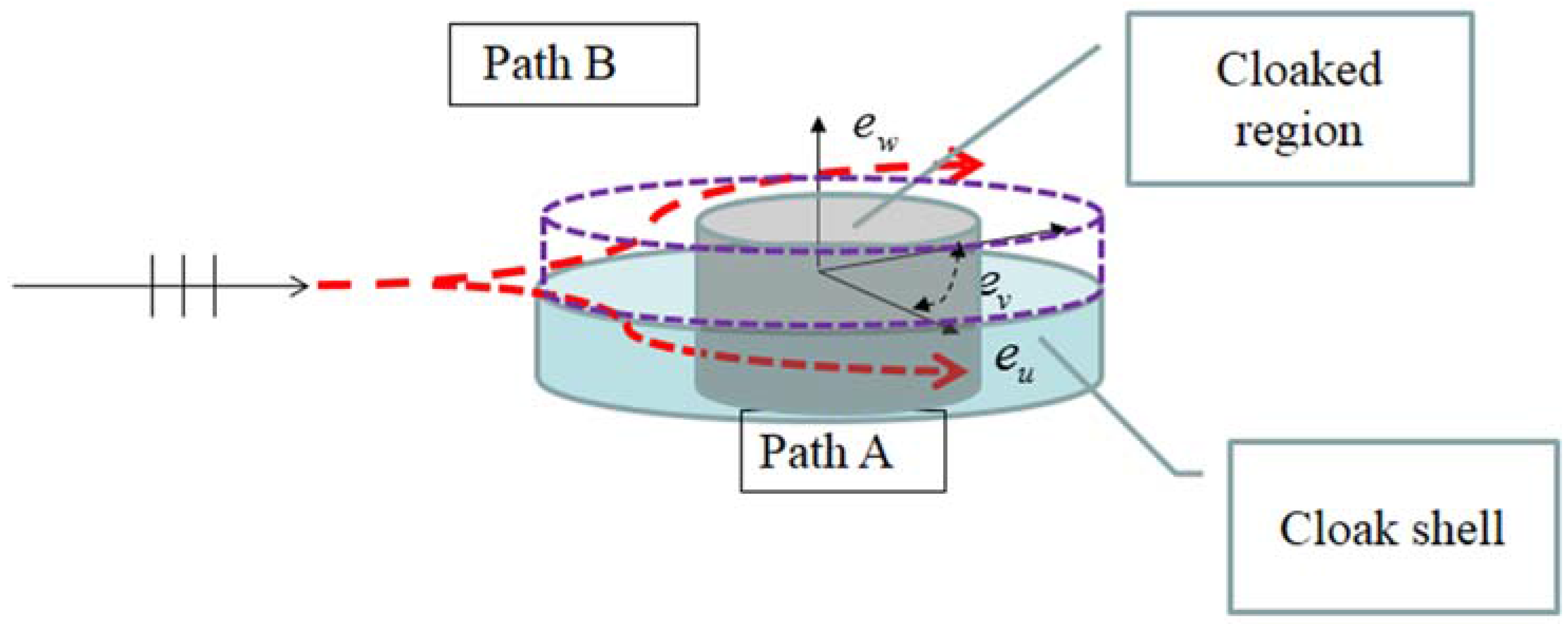
Figure 6.
The three layers of meta-composite structures forming the cloak shell region. Each block element in the layer is designed according to the spatially anisotropic properties of the cloak shell through impedance design.
Figure 6.
The three layers of meta-composite structures forming the cloak shell region. Each block element in the layer is designed according to the spatially anisotropic properties of the cloak shell through impedance design.
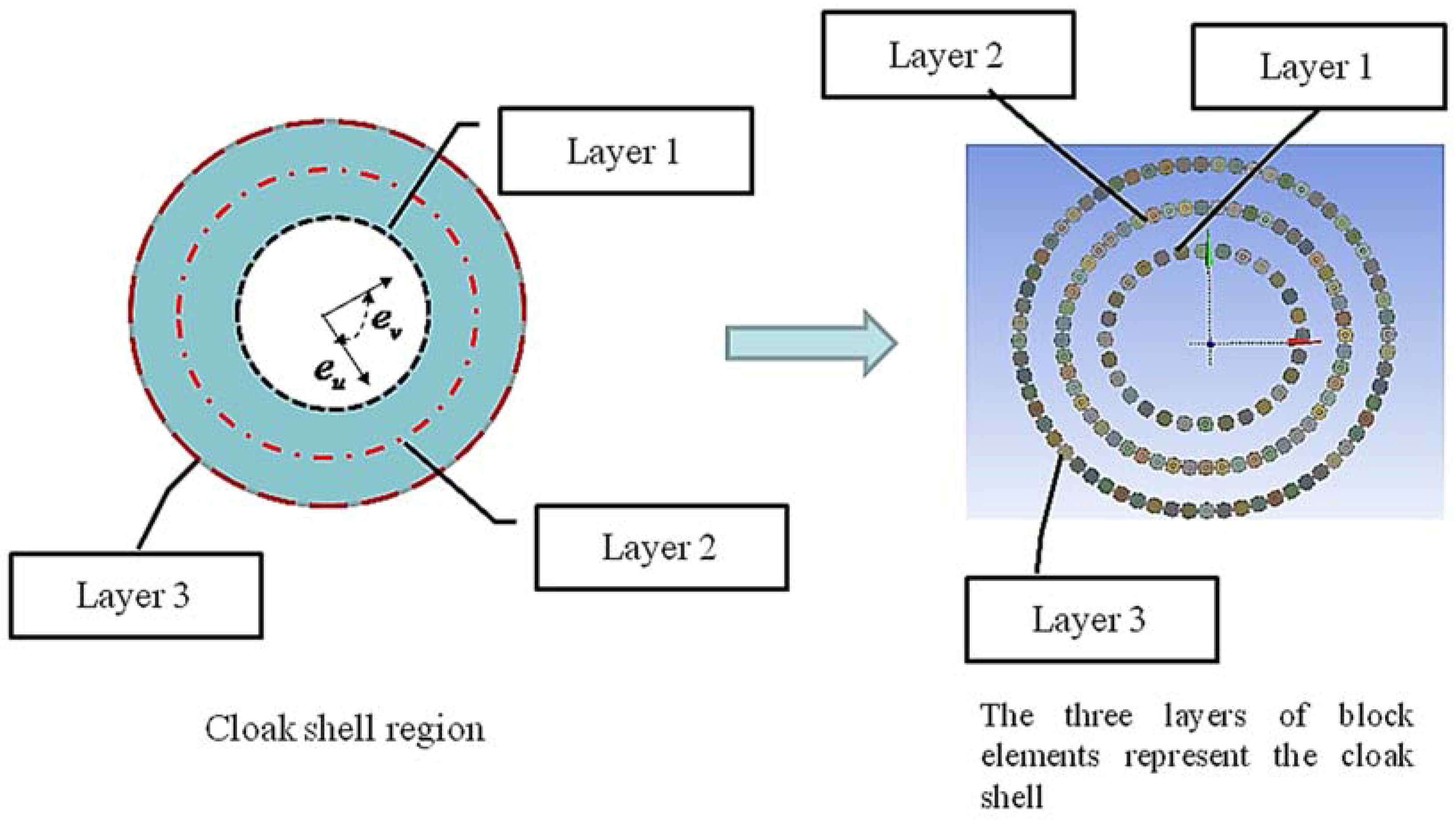
Figure 7.
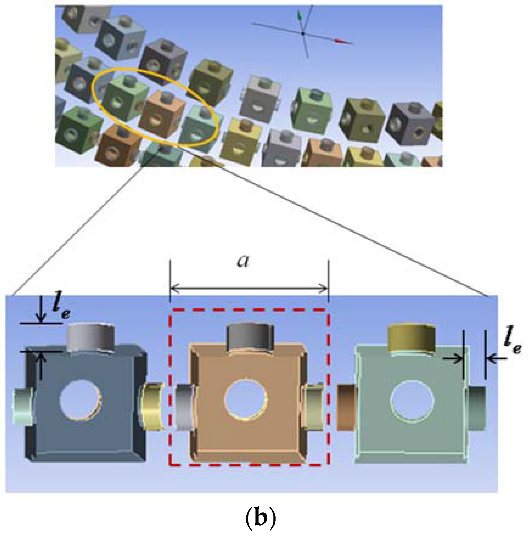
Structure of the meta-composite material used to make up the cloak shell: (a) the block elements include cavities and tubes arranged as circular elements in three layers. The inset on the upper right shows the details of single block elements with rectangular cavities and tubes. The bottom right inset exhibits both the cloak shell layered structures and cylinder object inside the cloaked region; (b) the part slices of the meta-composite material layer exhibit the interior cavity and tube in directions. The coefficient a explains the cross section dimension of and individual element, and represents the effective lengths of the tube connected with the cavity.
Figure 7.
Structure of the meta-composite material used to make up the cloak shell: (a) the block elements include cavities and tubes arranged as circular elements in three layers. The inset on the upper right shows the details of single block elements with rectangular cavities and tubes. The bottom right inset exhibits both the cloak shell layered structures and cylinder object inside the cloaked region; (b) the part slices of the meta-composite material layer exhibit the interior cavity and tube in directions. The coefficient a explains the cross section dimension of and individual element, and represents the effective lengths of the tube connected with the cavity.
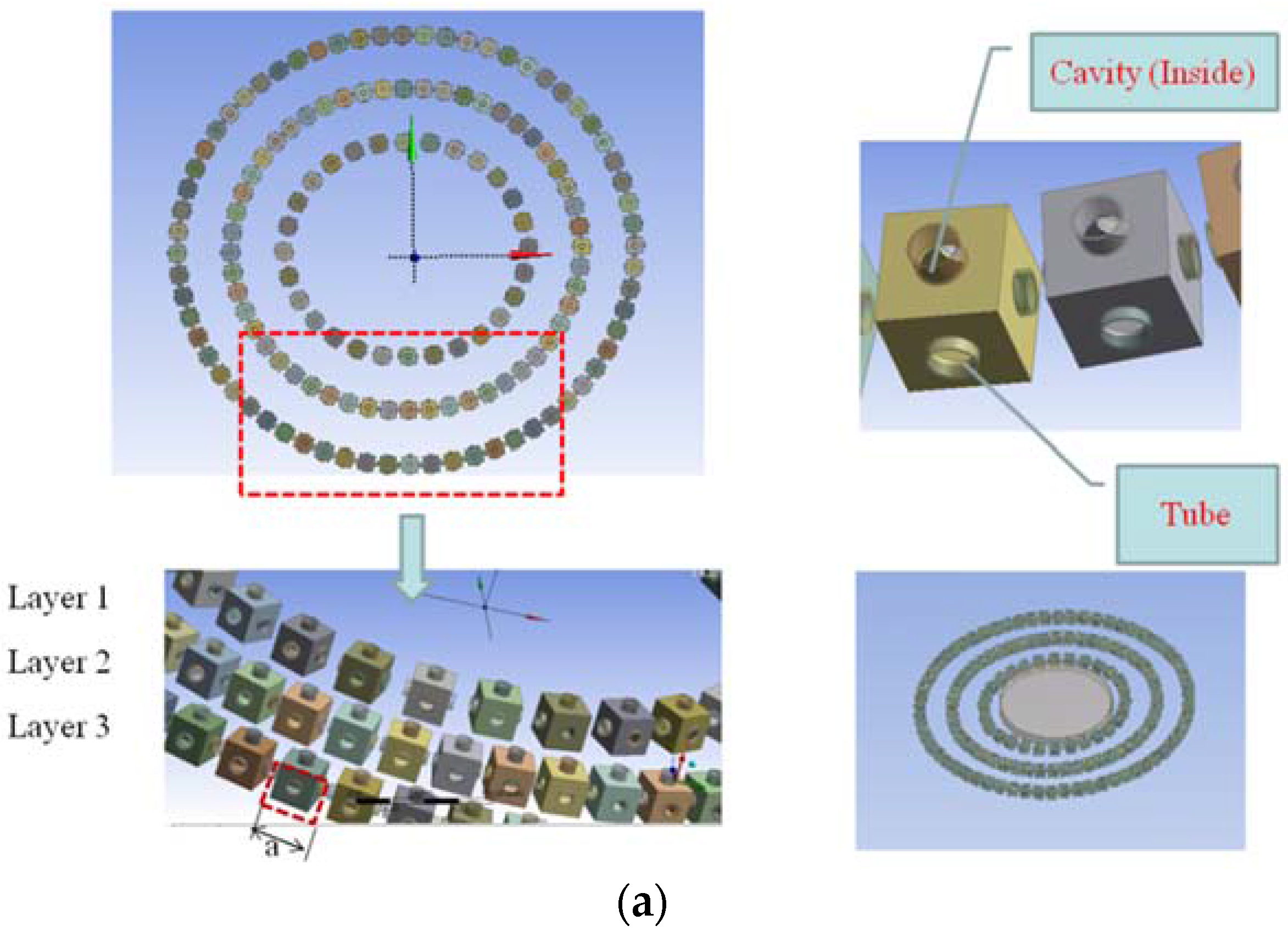

Figure 8.
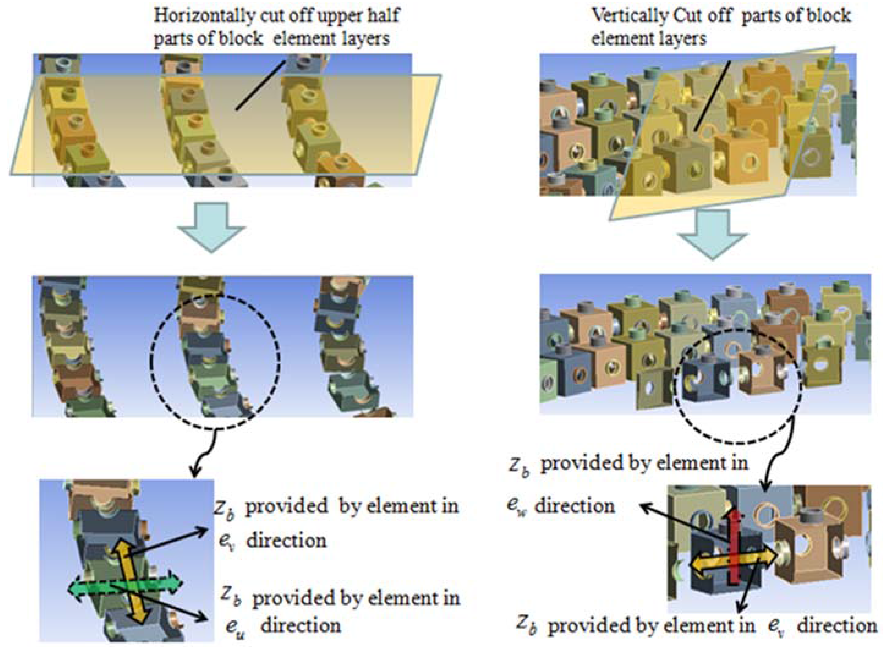
The interior details of the meta-composite material structure. The block elements include cavities and tubes arranged as circular elements in three layers. The inset on the left shows the details of block elements with rectangular cavities and tubes sliced by a surface in the – plane. The right inset presents details of the block elements sliced by a surface in the – plane. They exhibit the details of the cloak shell layered structures inside the cloaked region. The combination of cavity and tubes of the block element provides the acoustic impedance value in specific , , and directions, respectively.
Figure 8.
The interior details of the meta-composite material structure. The block elements include cavities and tubes arranged as circular elements in three layers. The inset on the left shows the details of block elements with rectangular cavities and tubes sliced by a surface in the – plane. The right inset presents details of the block elements sliced by a surface in the – plane. They exhibit the details of the cloak shell layered structures inside the cloaked region. The combination of cavity and tubes of the block element provides the acoustic impedance value in specific , , and directions, respectively.

Figure 9.
Spatial distribution of block element tube lengths of the cloak shell (Unit: mm): (a) tube length distribution around the cloak shell in the direction, (b) in the direction, and (c) in the direction.
Figure 9.
Spatial distribution of block element tube lengths of the cloak shell (Unit: mm): (a) tube length distribution around the cloak shell in the direction, (b) in the direction, and (c) in the direction.
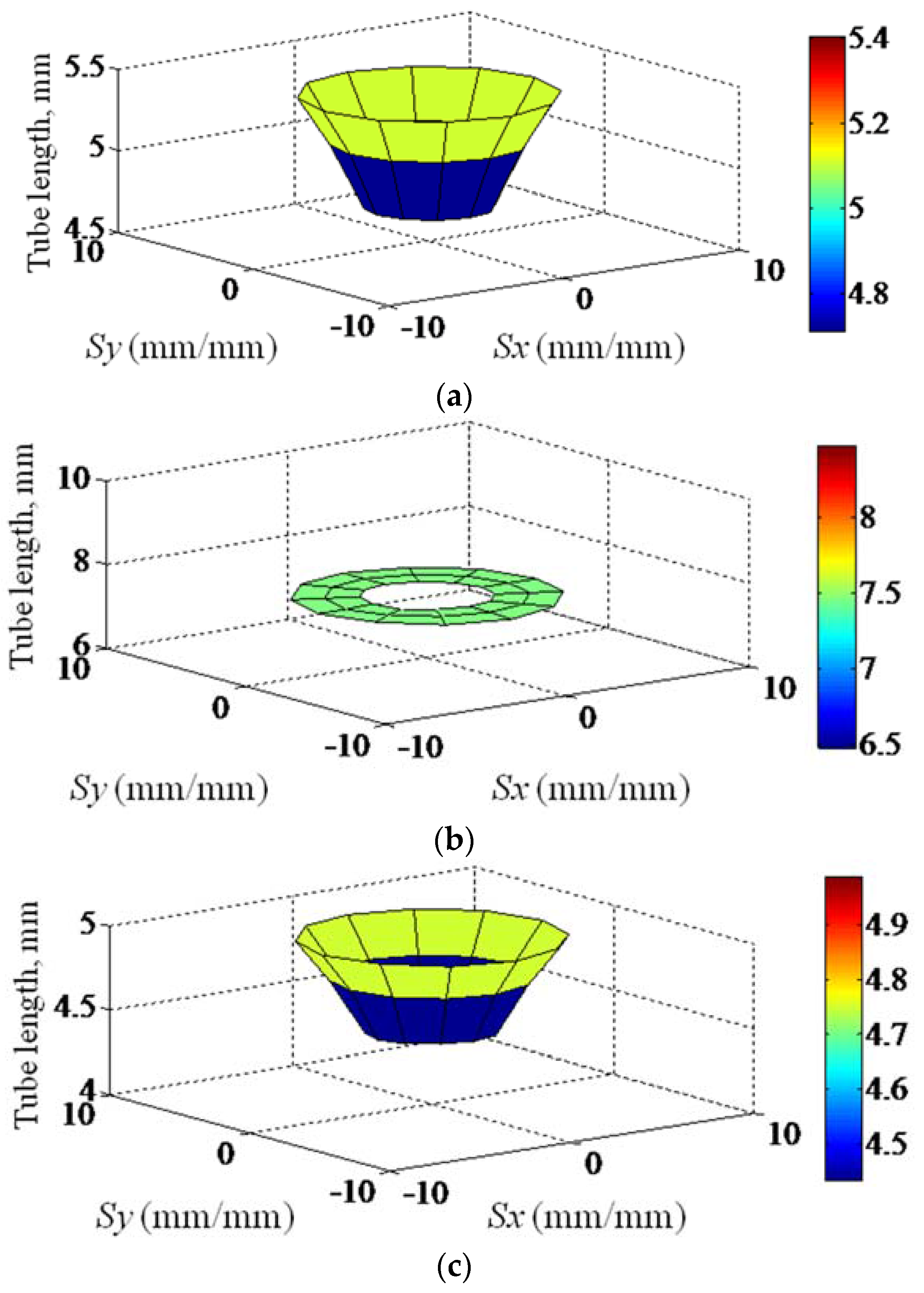
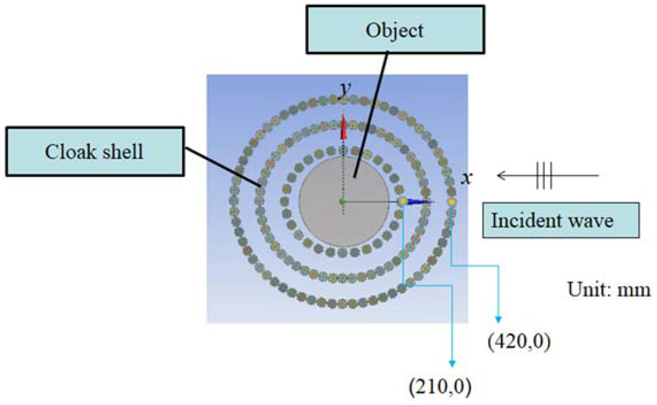
Figure 10.
Geometry setup used in numerical analysis: plane waves from the right side of the cloak shell are guided along a pre-determined path around the cloak shell away from the cylinder object (radius = 185 mm, height = 30 mm) inside the shell.
Figure 10.
Geometry setup used in numerical analysis: plane waves from the right side of the cloak shell are guided along a pre-determined path around the cloak shell away from the cylinder object (radius = 185 mm, height = 30 mm) inside the shell.

Figure 11.
The 3D geometric models and boundary conditions in numerical analysis. The object and cloak shell are enclosed inside a rectangular acoustic domain (5000 mm × 2500 mm × 100 mm) for a background medium (air). Surfaces A and B are assumed to be radiation boundaries and the other surfaces of acoustic domain are assumed to be the free surface. The 3D geometric model is meshed using a fluid structure interaction (FSI) interface to represent a fluid–structure interaction.

Figure 12.
Wave field of uncloaked object (upper plot), cloaked object (middle plot), and free field at 800 Hz. Plane waves with a specific frequency propagate from right to left. The dotted lines indicate the geometry of the cloaked object and cloak shell.
Figure 12.
Wave field of uncloaked object (upper plot), cloaked object (middle plot), and free field at 800 Hz. Plane waves with a specific frequency propagate from right to left. The dotted lines indicate the geometry of the cloaked object and cloak shell.

Figure 13.
Wave field of uncloaked object (upper plot), cloaked object (middle plot), and free field at 1000 Hz. Plane waves with a specific frequency propagate from right to left. The dotted lines indicate the geometry of the cloaked object and cloak shell.
Figure 13.
Wave field of uncloaked object (upper plot), cloaked object (middle plot), and free field at 1000 Hz. Plane waves with a specific frequency propagate from right to left. The dotted lines indicate the geometry of the cloaked object and cloak shell.

Figure 14.
The wave field of the uncloaked object (upper plot), the cloaked object (middle plot), and free field at 1250 Hz. Plane waves with a specific frequency propagate from right to left. The dotted lines indicate the geometry of the cloaked object and cloak shell.
Figure 14.
The wave field of the uncloaked object (upper plot), the cloaked object (middle plot), and free field at 1250 Hz. Plane waves with a specific frequency propagate from right to left. The dotted lines indicate the geometry of the cloaked object and cloak shell.

Figure 15.
The resulting scattering fields of cloaked and uncloaked cases of incident wave at 1000 Hz. In (a) the uncloaked case, the incident wave interacts directly with the object and causes scattering in most directions (Region A) and strong scattering disturbances in the forward direction (Shadow Region B). In (b) the cloaked case, the anisotropic cloak shell guided waves at the center to pass around the cloak shell and restored the waves behind the cloak shell, reducing the disturbance led to the resulting scattering field of both forward and backward directions (Region C) with a far flatter wave front as in a free field.
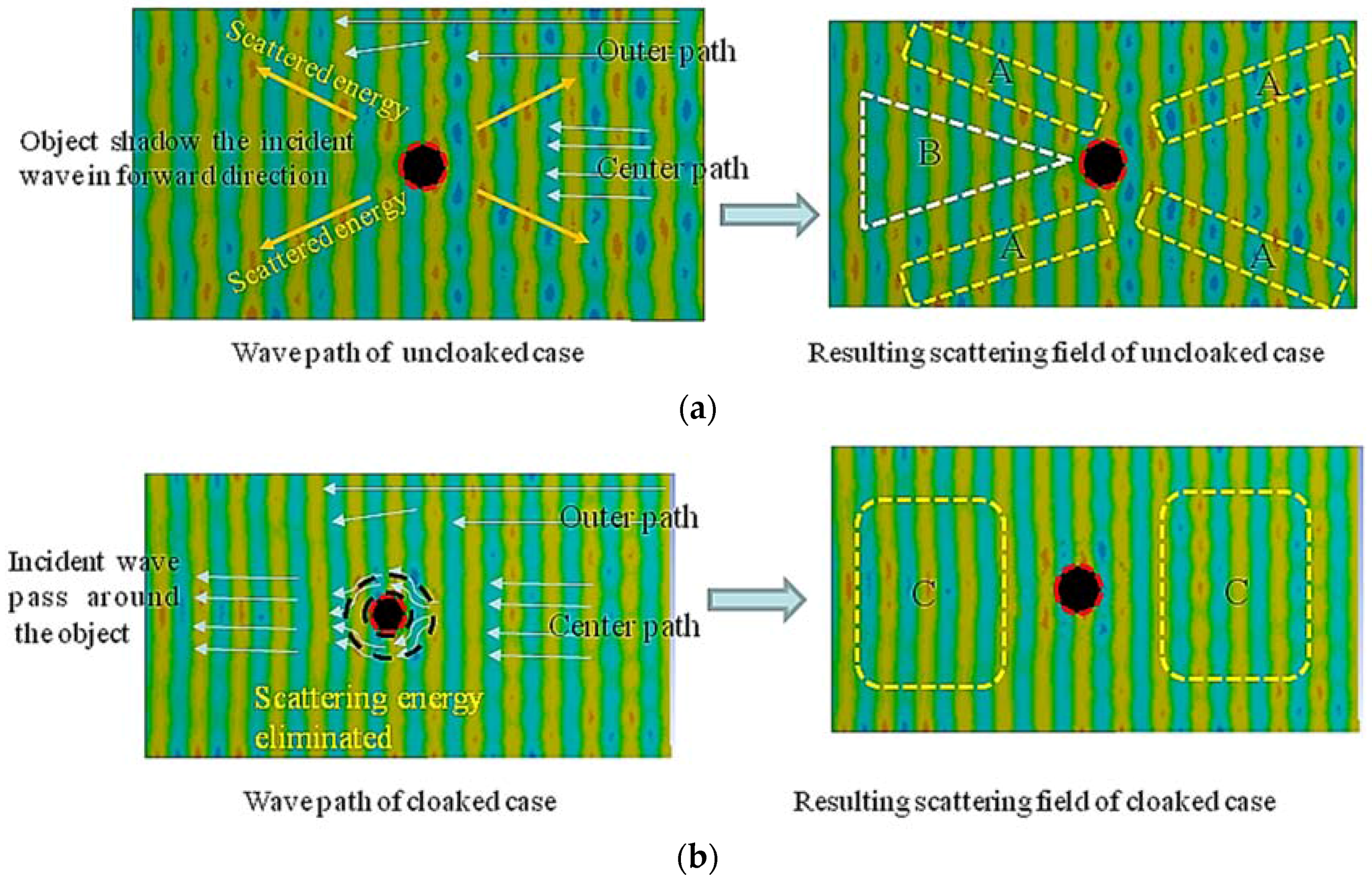
Figure 16.
Position of section lines in acoustic scattering field. To determine peak pressure field values, the section path lines were set between x = −1000 mm and x = −1500 mm.
Figure 16.
Position of section lines in acoustic scattering field. To determine peak pressure field values, the section path lines were set between x = −1000 mm and x = −1500 mm.

Figure 17.
Average visibility values in cases of the cloaked object and the uncloaked object at frequencies from 630 Hz, 715 Hz, 800 Hz, 900 Hz, 1000 Hz, 1125 Hz, 1250 Hz, 1425 Hz, and 1600 Hz.
Figure 17.
Average visibility values in cases of the cloaked object and the uncloaked object at frequencies from 630 Hz, 715 Hz, 800 Hz, 900 Hz, 1000 Hz, 1125 Hz, 1250 Hz, 1425 Hz, and 1600 Hz.
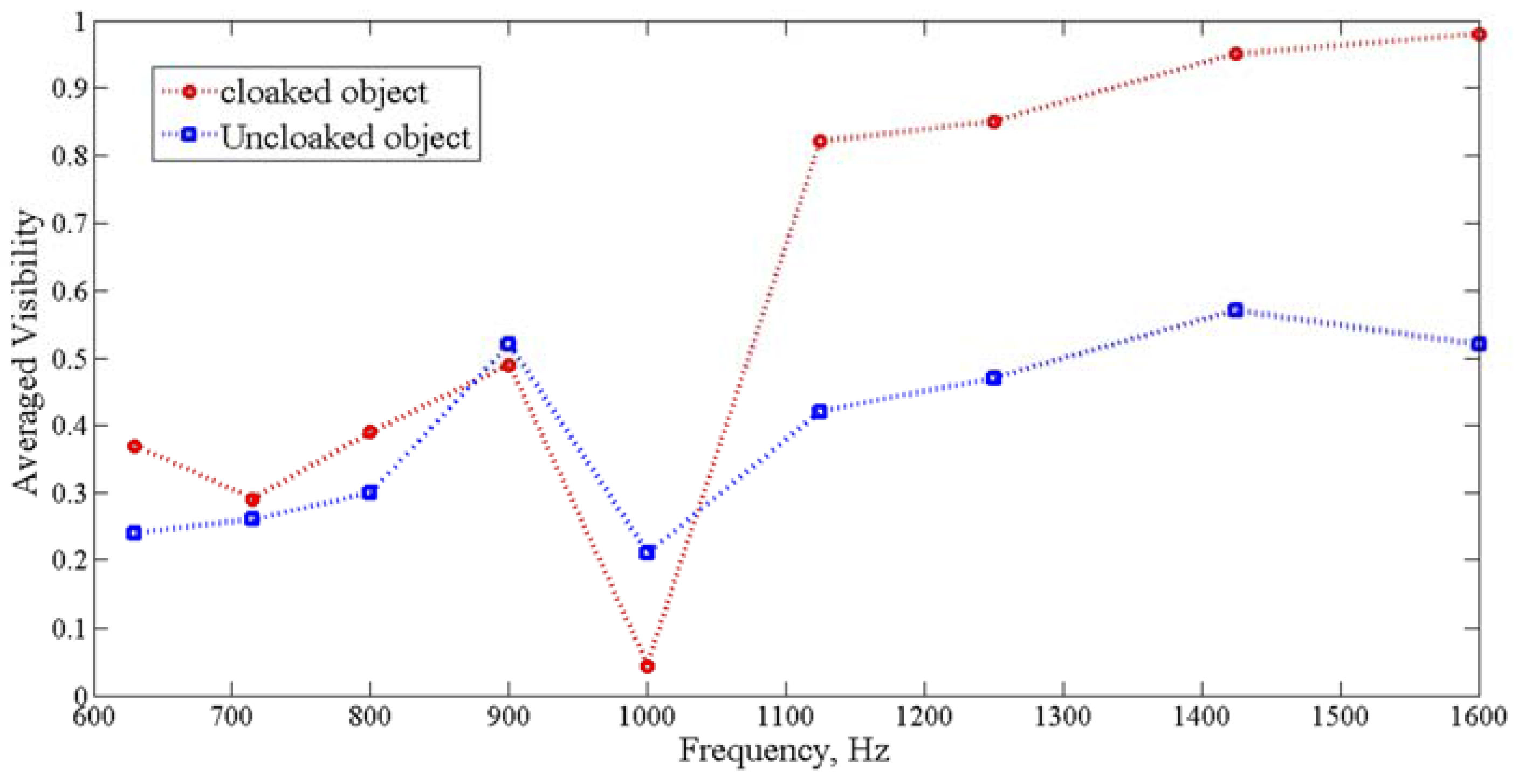
Figure 18.
The sampling line positions for polar scattering pattern evaluation. The line is sampled around the object to investigate the scattering polar pattern.
Figure 18.
The sampling line positions for polar scattering pattern evaluation. The line is sampled around the object to investigate the scattering polar pattern.
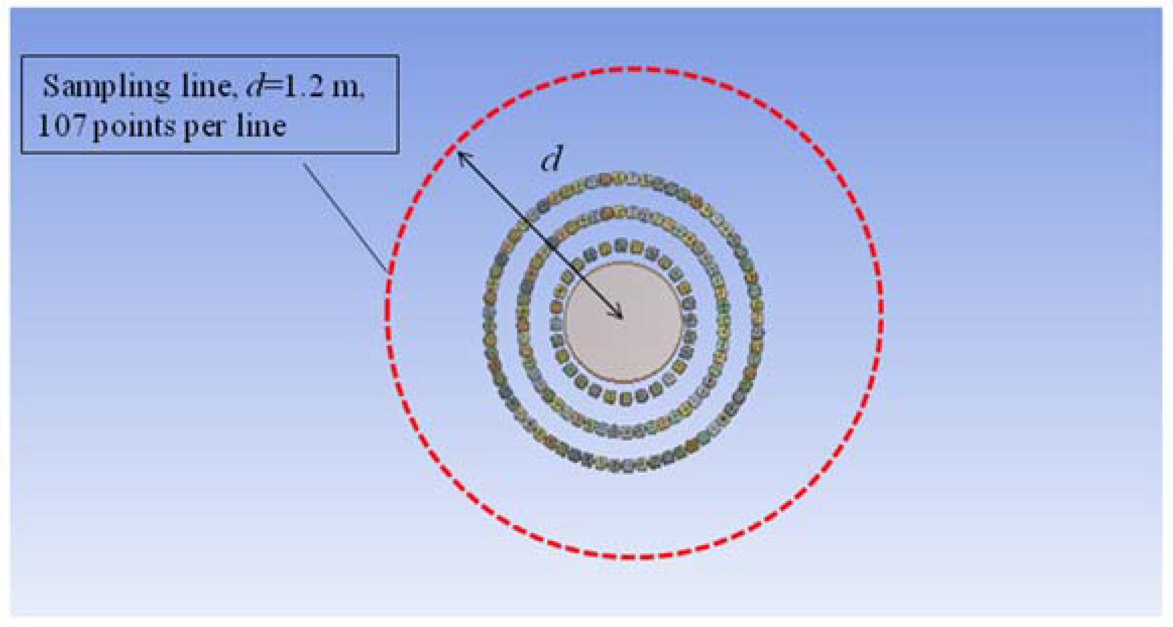
Figure 19.
The intensity polar pattern diagram of uncloaked (left side) and cloaked objects (right side) with incident wave frequency f = 800 Hz; (a) the intensity polar pattern of the total sound field; (b) the intensity polar pattern diagram of the normalized sound field (scattered field of the object).

Figure 20.
The intensity polar pattern diagram of the uncloaked (left side) and cloaked objects (right side) with incident wave frequency f = 1000 Hz: (a) the intensity polar pattern of the total sound field; (b) the intensity polar pattern diagram of the normalized sound field (scattered field of the object).
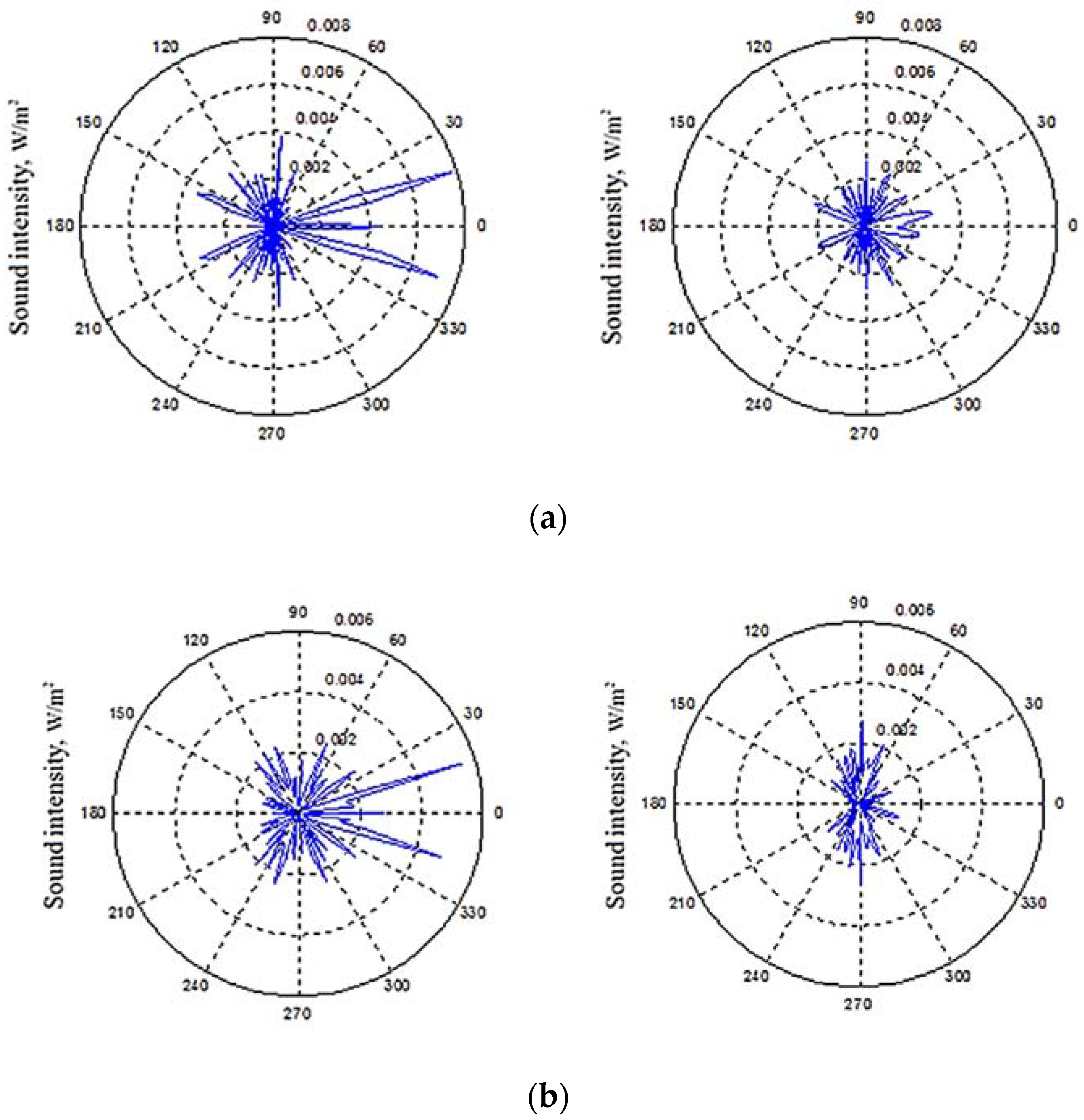
Figure 21.
The intensity polar pattern diagram of uncloaked (left side) and cloaked objects (right side) with incident wave frequency f = 1250 Hz: (a) the intensity polar pattern of the total sound field; (b) the intensity polar pattern diagram of the normalized sound field (scattered field of the object).


Figure 22.
The sound pressure sampling line, sampling surface, and results for the cross-section value (CSV) calculation of the scattered field: (a) the enclosed cylinder surface and sampling line positions; (b) the normalized sound field (scattered field) CSV results of cloaked and uncloaked cases.
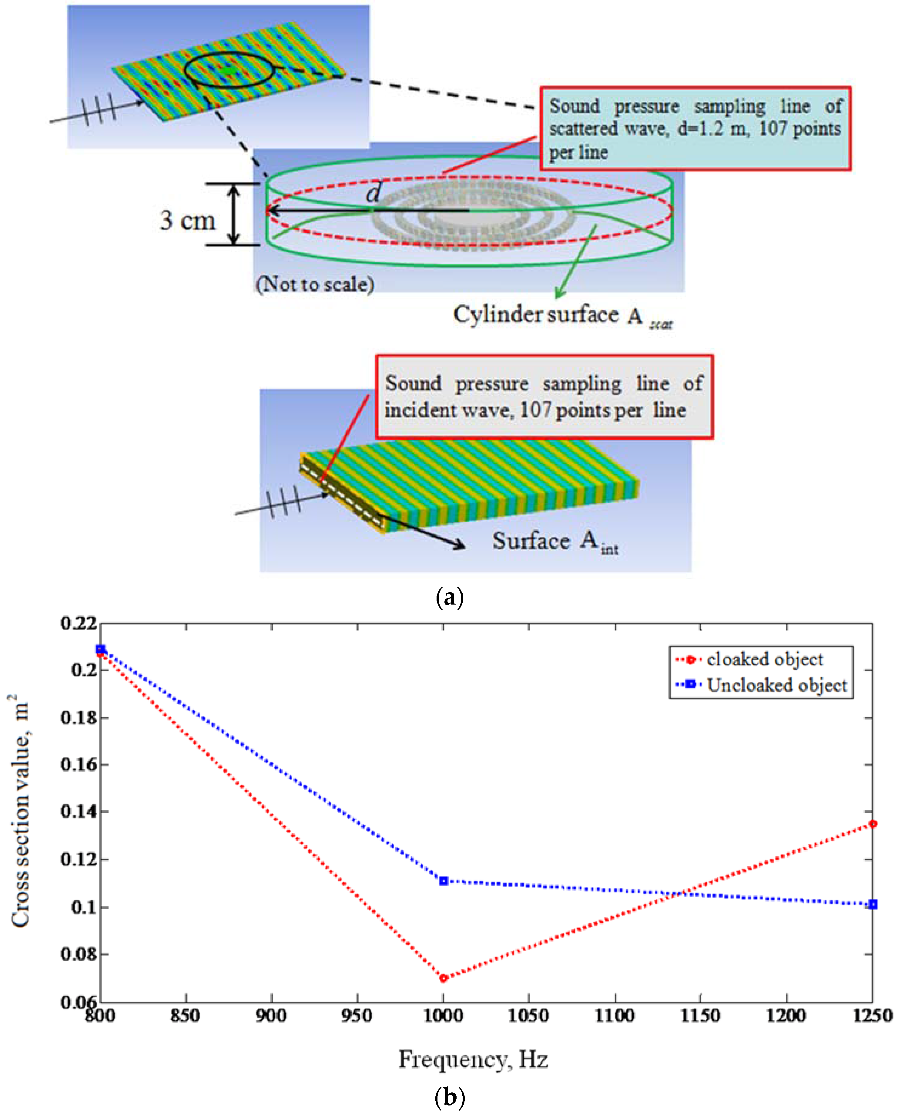
Figure 23.
(a) 3D diagram of single block structures (multiple elements were produced simultaneously by a 3D printer); (b) 3D-printed block element components; (c) assembled block elements.
Figure 23.
(a) 3D diagram of single block structures (multiple elements were produced simultaneously by a 3D printer); (b) 3D-printed block element components; (c) assembled block elements.
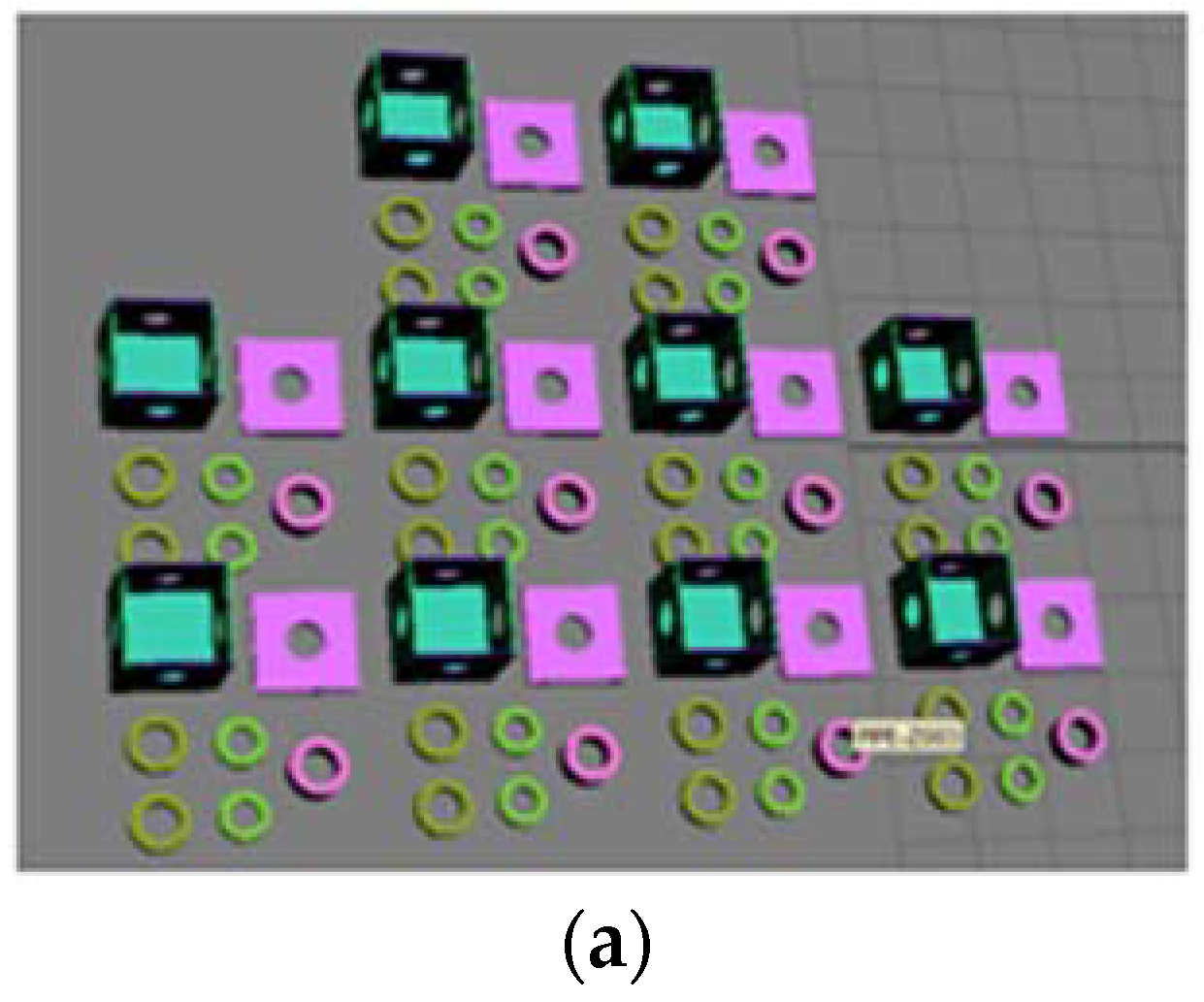
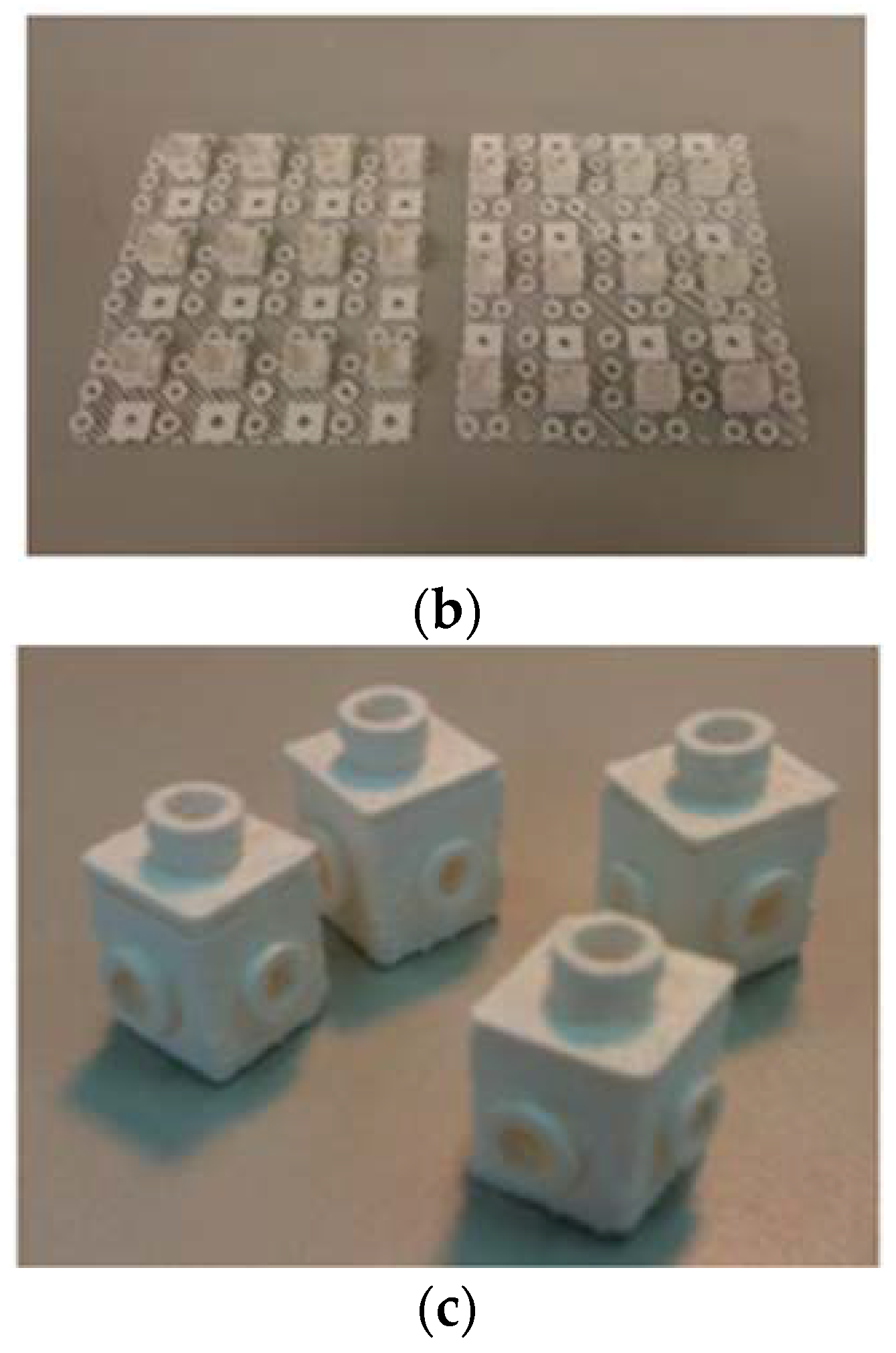
Figure 24.
Experimental setup for measurement in a semi-anechoic room: (a) the sound source is excited by B&K Type 4296 omni-directional sound source at 2000 Hz apart from test specimen at 4000 mm; (b) the near field measurement inside the cloak shell region was measured using a single free-field microphone scanned in the region between Cx = 0~342 mm and Cy = 0~152 mm, as indicated by the dotted line. (c) The results indicate the wave propagation behavior inside the half shell region.


Figure 25.
Sound field measurements obtained within the zone affected by the cloak shell: (a) only the specimen supporter as a reference sound field; (b) the object; (c) the cloak shell; (d) the object and the cloak shell.
Figure 25.
Sound field measurements obtained within the zone affected by the cloak shell: (a) only the specimen supporter as a reference sound field; (b) the object; (c) the cloak shell; (d) the object and the cloak shell.

Figure 26.
Normalized sound field measurements obtained within zone affected by cloak shell: (a) the object only; (b) the cloak shell only; (c) object and cloak shell combined. The red dotted line indicates the space occupied by object.
Figure 26.
Normalized sound field measurements obtained within zone affected by cloak shell: (a) the object only; (b) the cloak shell only; (c) object and cloak shell combined. The red dotted line indicates the space occupied by object.

Figure 27.
The scattering far field was measured using a single free-field microphone scanned in the forward scattering region between Ex = 0~760 mm and Ey = 0~190 mm, as indicated by the dotted line. The measurement step size is 19 mm in both directions.
Figure 27.
The scattering far field was measured using a single free-field microphone scanned in the forward scattering region between Ex = 0~760 mm and Ey = 0~190 mm, as indicated by the dotted line. The measurement step size is 19 mm in both directions.

Figure 28.
Sound field measurements results: (a) incident free field (only specimen supporter in the space) as a reference sound field; (b) uncloaked object; (c) cloaked object.
Figure 28.
Sound field measurements results: (a) incident free field (only specimen supporter in the space) as a reference sound field; (b) uncloaked object; (c) cloaked object.

Figure 29.
Normalized sound field results of scattering field: (a) uncloaked object; (b) cloaked object.
Figure 29.
Normalized sound field results of scattering field: (a) uncloaked object; (b) cloaked object.

Table 1.
Design parameters of block elements used in the cloak shell.
| Layer Number | Element Size a (mm) | Cavity Volume b × b × b (mm3) | Tube Inner Diameter c (mm) | Element Number/per Layer | |
|---|---|---|---|---|---|
| 1 | 55 | 27,000 | 11.28 | 28 | |
| 2 | 41.2 | 27,000 | -direction | 11.28 | 52 |
| -direction | 9 | ||||
| 3 | 43.9 | 27,000 | 11.28 | 64 | |
| Block element dimensions |  |  | |||
© 2017 by the authors. Licensee MDPI, Basel, Switzerland. This article is an open access article distributed under the terms and conditions of the Creative Commons Attribution (CC BY) license (http://creativecommons.org/licenses/by/4.0/).
Share and Cite
MDPI and ACS Style
Yang, S.-K.; Lin, J.-C.; Cheng, J.-W. The Experimental Realization of an Acoustic Cloak in Air with a Meta-Composite Shell. Appl. Sci. 2017, 7, 456. https://doi.org/10.3390/app7050456
AMA Style
Yang S-K, Lin J-C, Cheng J-W. The Experimental Realization of an Acoustic Cloak in Air with a Meta-Composite Shell. Applied Sciences. 2017; 7(5):456. https://doi.org/10.3390/app7050456
Chicago/Turabian StyleYang, Shiuh-Kuang, Jau-Cho Lin, and Jyin-Wen Cheng. 2017. "The Experimental Realization of an Acoustic Cloak in Air with a Meta-Composite Shell" Applied Sciences 7, no. 5: 456. https://doi.org/10.3390/app7050456
Note that from the first issue of 2016, this journal uses article numbers instead of page numbers. See further details here.