
Random Vibration Suppression of a Truss Core Sandwich Panel Using Independent Modal Resonant Shunt and Modal Criterion

Research Center of Applied Mechanics, School of Mechano-Electronic Engineering, Xidian University, P.O. Box 187, Xi’an 710071, China
*
Author to whom correspondence should be addressed.
Appl. Sci. 2017, 7(5), 496; https://doi.org/10.3390/app7050496
Submission received: 21 March 2017
/
Revised: 28 April 2017
/
Accepted: 9 May 2017
/
Published: 11 May 2017
Abstract
:The aim of this paper is to suppress the random spatial vibration of the face sheet of a lightly damped truss core sandwich panel structure. Because broad-bandwidth vibration energy is concentrated in resonance peaks for lightly damped structures, an independent modal resonant shunt control method is utilized to add damping ratios to the chosen modes. In this method, each piezoelectric transducer is connected to a single resonant shunt which is tuned to control the vibration of a single mode. An H2 norm sensitivity-based modal criterion is proposed in order to determine which modes to control under a given bandwidth of excitation and input-output condition. Numerical simulation is implemented while control strategies with different controlled modes are compared. The result shows that the independent modal resonant shunt control method can suppress random vibration response of the face sheet by using only a few piezoelectric transducers, and the proposed modal criterion can be used to determine which modes to control.
1. Introduction
Structural vibration under random excitation is a common kind of response in engineering applications. Random vibration is often harmful since the fatigue life and performance of the structure can deteriorate, especially in civil engineering, vehicles and aerospace, so a vibration suppression technique is necessary. There are three main kinds of vibration control: passive, semi-active and active [1]. Active vibration control using smart materials can achieve better performance but it also has many disadvantages: required energy input, need for sensing and feedback segments, complexity of implementation, etc. These shortcomings are more prominent in random vibrations because random responses are often persistent, uncertain and high-frequency. Also, some kinds of active control methods are not guaranteed to be stable. Therefore, semi-active and passive vibration controls are still the main methods for random vibration control of engineering structures. For example, Park [2] utilized magneto-rheological dampers to control car vibrations due to random road conditions. To suppress vibrations under narrow-band excitations, Sinha [3] proposed a mixed H2/H∞ optimization method for a vibration absorber. A hybrid vibration absorber was proposed in [4] for random vibration control of cantilever beams. However, most kinds of passive and semi-active devices introduce considerable mass to the structure, which limits their applications.
Shunt circuit damping is a kind of passive or semi-active vibration control technique raised by Hagood and Von Flotow [5]. In this method the mechanical energy of the vibrating structure is first converted into electrical energy and then dissipated by the resistance in the shunt circuit. According to the type of transducer, shunt circuit damping can be divided into piezoelectric shunt circuits and electromagnetic shunt circuits [6], and the types of shunt circuit include resistive shunt circuits [7], resonant shunt circuits [8], negative capacity shunt circuits [9], switch shunt circuits [10], etc. Among various shunt damping methods, the piezoelectric resonant shunt is the most widely used method. This method is a passive dissipation method but is sometimes classified as a semi-active method because energy is usually needed to synthesize inductance to avoid using a large-mass inductance coil. In this article the following classification criterion is used: a shunt inductance is said to be passive if it does not input energy into the structure [11].
For broadband random vibration of lightly damped structures, the response energy is concentrated in resonance peaks, so vibration suppression can be realized by adding damping ratios to the modes in the bandwidth. There are many papers that aim for multimode vibration control using a resonant shunt. Wu [12] employed current blocking branches while Hollkamp [13] used parallel RLC shunts. Alessandroni [14] utilized distributed piezoelectric transducers and distributed electric networks to suppress broadband vibration. In these kinds of methods, in order to realize frequency selection of different modes, a large number of capacitances and inductances must be employed, which increases the complexity of the shunts. Thus, a kind of independent modal resonant shunt was proposed in [15]. In this method, a single mode is controlled using a single transducer and a single shunt circuit. The piezoelectric transducers and resonant shunt circuit are more independent from each other compared with other kinds of multimode shunt methods. Thus this method possesses advantages like fewer inductances and capacitances; greater reliability; easier to set up; etc.
In this study, an independent modal resonant shunt is employed to suppress random vibration of a kind of lightly damped structure. In this method, the number of transducers equals the number of modes to be controlled, so it is uneconomical to control all the modes in the bandwidth of excitation. On the one hand, under the given input-output condition of the structure, the contributions of different modes to the root mean square (RMS) response are distinct and the decrement of these contributions when adding damping is also distinct. On the other hand, the amount of added damping ratio is related to the location of transducers. For example, for a truss-like structure, the damping effect of a mode using resonant shunt depends on the fraction of modal strain energy (MSE) of the rod which is replaced with transducer. For a different mode, the maximum fraction of modal strain energy among all the rods is different, which means that in the independent modal resonant shunt method, a different mode has different controllability. So, in this study, a modal criterion is proposed considering the sensitivity of mode H2 norm with the damping ratio and fraction of MSE.
The aim of this study is to apply the independent modal resonant shunt for the random vibration suppression of a truss-cored sandwich panel called a Kagome structure using the proposed modal criterion. This paper is organized as follows: In Section 2, the Kagome structure is introduced and the finite element model of the piezoelectric shunted structure is presented. The independent modal resonant shunt method is summarized in Section 3. In Section 4 the modal criterion is detailed. The validity of the proposed method is demonstrated through the time-domain simulation of the random excitation responses of face sheet. Finally, conclusions are drawn in Section 5.
2. Finite Element Model of Kagome Structure with Piezoelectric Shunt
2.1. Truss Core Kagome Sandwich Panel Structure
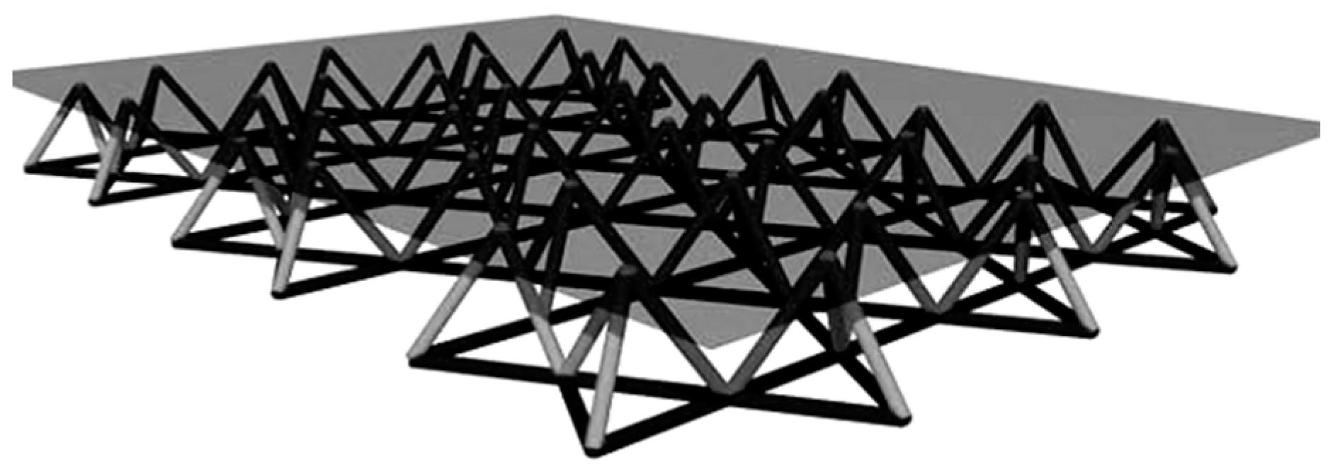
The truss core Kagome sandwich panel [16] which is a kind of high-authority morphing structure, consists of a solid face sheet, a tetrahedral core and a planar Kagome truss as the back-plane (see Figure 1). The character of this structure is that there is strong coupling between the out-of-plane deformation of the face sheet and the in-plane deformation of the truss back-plane. The benefit of this character is that morphing of the solid face sheet can be realized by replacing some rods in the back-plane planar truss with in-plane tension-compression actuators. While for panel-like structures, constrained layer damping [17] is usually used for passive damping and a piezoelectric patch [18] is often utilized for active damping, the character of a Kagome structure can be exploited for passive/active controls by replacing a small portion of the rods in the planar Kagome truss with in-plane dampers [19] or actuators [20], which will not destroy the planeness of the face sheet. In this study, the rods in the planar truss are replaced by piezoelectric transducers to convert the mechanical energy to electric energy, which is dissipated by the resistance.
The materials and parameters of the Kagome structure are listed in Table 1. There are a total of 546 truss rods in the planer Kagome truss. The boundary condition is clamped–clamped. The total weight of this structure is 5.8 kg.
2.2. Structure with Resonant Shunt Circuits
A kind of piezoelectric stack transducer is employed (see Figure 4a) to replace a small number of rods in the planar Kagome truss. The transducer is mainly composed of a piezoelectric stack, outer casing, preloading spring and two link rods. A sphere joint is used to prevent the piezoelectric stack from bending and torsion. Each transducer is connected to an RL shunt (see Figure 4b). The weight of the transducer is about 8 g, which is four times that of the truss rod (2 g). When only a small number of transducers are used, the increment of the total weight can be neglected.
The Lagrange–Maxwell equation is employed to build a finite element model of the mechano-electric structure with n transducers and n shunt circuits.
The kinetic energy of the structure is:
where [Ms] is the mass matrix of Kagome structure with piezoelectric transducers and {xs} is the displacement vector of the element nodes.
The potential energy of the structure is:
where [Ks] represents the stiffness matrix of Kagome structure with piezoelectric transducers.
The magnetic energy of the inductances is:
in which [L] is a diagonal matrix whose elements are value of inductances in the shunt circuits:
and vector {q} contains electric charge of different shunt circuits.
Supposing all the transducers have the same characters, the electrical energy of the transducers is:
where C is unloaded capacitance of the piezoelectric stack which includes n piezoelectric disks, Ka is the short-circuited electrode stiffness of piezoelectric transducer, k is the electromechanical coupling factor, d33 is the piezoelectric constant and [Bt] is the position matrix of the transducers. The parameters of the stack transducers can be found in [21].
Define the dissipation function P which represents the energy dissipation of the damping and resistances as:
where [Ds] is damping matrix of the mechanical structure and [R] is a diagonal matrix whose elements are value of resistances in the shunt circuits:
Combining the mechanical and electrical coordinates as:
the Lagrange–Maxwell equation of the unloaded structure takes the form as:
where
Using the Lagrange–Maxwell equation, the dynamical equation of the mechano-electric structure can be obtained as:
where
and {b}i is the ith row of [B]t.
3. Independent Modal Resonant Shunt Circuit
There is a two-step frequency-selecting mechanism of energy in independent modal resonant shunt circuit method. For each mode, first, a piezoelectric transducer is allocated to convert the mechanical energy of this mode into electric energy. Then a resonant shunt is connected to this transducer to dissipate the electric energy of this mode. Due to the fine frequency-selecting property of the RLC resonant circuit, the second step plays a major role. Because of this frequency-selecting process, when the frequencies of different modes are well separated, each shunt is almost independent. Moreover, because only a small part of the rods is replaced by transducers, the dynamical characteristics of the structure are almost invariant. Thus, adding, changing or removing a shunt does not affect the effects of other shunts. The mechanism of this method is illustrated in Figure 5.
In order to enhance the performance of the shunt circuit, first, the location of the modal transducer must be optimized to convert the energy of this mode into electric energy as more as possible. Truncate Equation (11) using only the ith mechanical mode (mode of Kagome structure without shunt circuits), the following system can be obtained:
where xsi is the coordinate of the ith mode, ωoi is open-electrode frequency of the ith mode with open-electrode transducer stiffness Kao:
and λi is defined as:
where {ϕ}i represents modal shape of the ith mode of the mechanical structure. Obviously, λi reflects the coupling strength of piezoelectric transducer with the ith mode. Thus, for mode i, the transducer must be located to replace the rod with maximal λi.
Because the mathematical model of a resonant shunt is similar to a tuned mass damper, the key problem is tuning the values of inductance and resistance in every shunt to achieve optimal performance. There have been several methods to optimize the RL value of the resonant shunt. Preumont [21] provided the optimal RL value based on root locus plot while Thomas [22] used pole placement and transfer function criterion. But these tuning methods were based on one degree-of-freedom (DOF) systems. In [15] it is shown that when the number of mechanical DOF is far greater than the electrical DOF, the optimal RL value based on single-mode truncation can lose effectiveness, so a full-order model must be used in the optimization process. In the independent modal resonant shunt circuit method, supposing there are n modes to control, owing to the independence between the shunts, the 2n-dimensional optimization problem can be reduced to 2n one-dimensional problems while each can be resolved by a simple heuristic search method summarized below:
- (1)
- (2)
- Calculate the eigenvalues of the structure coupled with the first shunt by solving complex eigenvalue problem of the full-order model. Through changing L value heuristically, make the frequency of the electrical mode close to its corresponding mechanical mode.
- (3)
- Make the damping ratio of the first mode as high as possible through changing R heuristically.
- (4)
- Move to the shunt of the next mode.
4. Modal Criterion for Random Vibration Suppression
In theory the response of all the modes in the bandwidth of the excitation must be considered and controlled. In themindependent modal resonant shunt method, the number of transducers equals the number of modes to be controlled, so a modal criterion is needed to indicate which modes are worthy to control with the given input-output condition of the structure in order to optimize the number of transducers. The state-space representation of the uncontrolled mechanical structure is:
The state vector {x} is as follows:
while system matrix [A] is:
The input matrix [B] consisting of 0 and 1 represents locations of the disturbances, {w} is the disturbance vector, and the output matrix [C] consisting of 0 and 1. The frequency-response function [G] is defined as the complex gain between {w} and {y}:
The relation between the power spectral density (PSD) of {w} and {y} is:
where the asterisk represents conjugate transpose.
When the disturbances are uncorrelated white noise, e.g., [Sw(ω)] = [I], the RMS response of the output of system (16) is:
This is indicated that the RMS power response equals the H2 norm of the system. For a lightly damped structure, the H2 norm can be approximated as [23]:
where N is the total number of modes in the bandwidth, and
is H2 norm of the ith mode.
Quantity of H2 norm of a mode represents the contribution of this mode to the response. A natural idea of modal criterion is using H2 norm of the modes, say, controlling the modes with highest H2 norm. However, in an independent modal resonant shunt, the added damping ratios cannot be an arbitrary set, as it is decided by the quantity λi in (15). In fact, λi is linked to the MSE of the replaced rod. In [21] it is indicated that the amount of the added damping ratio is directly proportional to square root of the fraction of MSE δi of the replaced rod, which can be calculated as:
where ωsi is the short-electrode frequency of the ith mode with short-electrode transducer stiffness Ka. Note that because the transducers are free of bending and torsion, only axial MSE is considered.
Thus, a modal criterion is proposed here using decrement of H2 norm of a mode when controlled by independent modal resonant shunt. Suppose there is an increment of modal damping ratio of mode i, Δξi, and the decrement of H2 norm of this mode is:
Finally, because Δξi is directly proportional to the square root of the fraction of MSE δi, the modal criterion is defined as:
From Equation (25), it can be seen that this modal criterion depends on the modal H2 norm, modal damping ratio and fraction of MSE of the replaced rod.
Therefore, for a random excitation with uniform spectrum in the bandwidth, the modal criterion (25) of all the modes in the bandwidth of the excitation will be calculated, and the modes with highest ηi are chosen to be controlled with priority.
5. Simulation and Discussion
In this section, the time-domain response of the Kagome structure is simulated to validate the efficiency of the proposed method. The Rayleigh damping model is applied to the structure so the structure damping matrix can be written as:
where α = 2.35 and β = 3.96 × 10⁻⁷ to set the modal damping ratios of mode 1 and 2 at 1‰. The modal damping ratio of mode i can be calculated using:
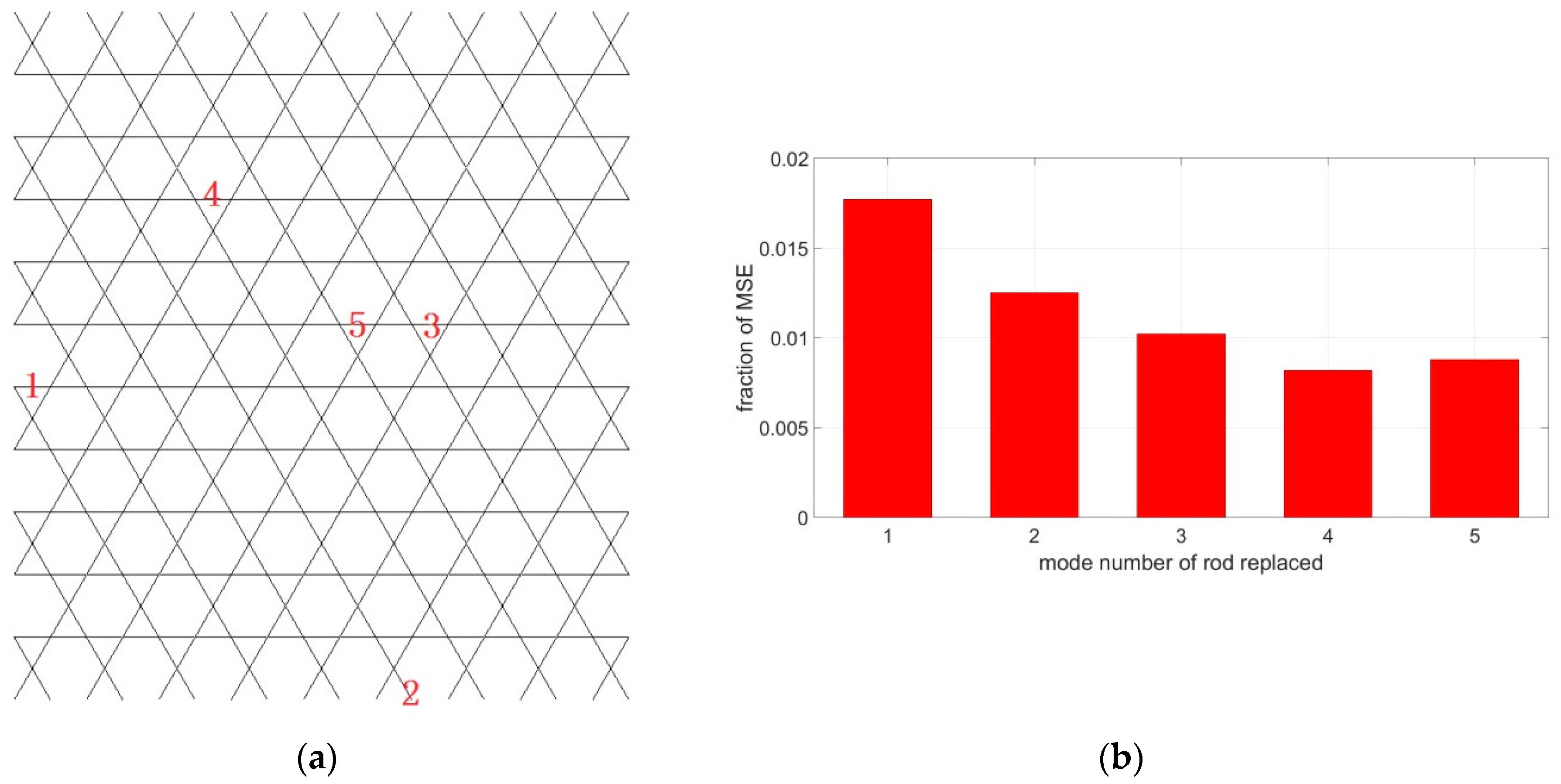
To validate the efficiency of the proposed method on the random response suppression, the response of the Kagome structure under the excitation of a vertically distributed band-limited white noise load on finite element nodes of the whole face sheet is simulated. The noise is with uniform PSD 0.2 N2/Hz in 0–800 Hz. The random forces on different nodes are uncorrelated. The purpose is to control the RMS response of vertical vibration of the whole face sheet, so the output DOF is also vertically DOF of the nodes of the whole solid face sheet. Because the upper bound of the excitation is 800 Hz, in Equation (22) only the first five modes are considered. The locations of the five transducers are decided as in Figure 6a through calculating λi, and their fraction of MSE are shown in Figure 6b.
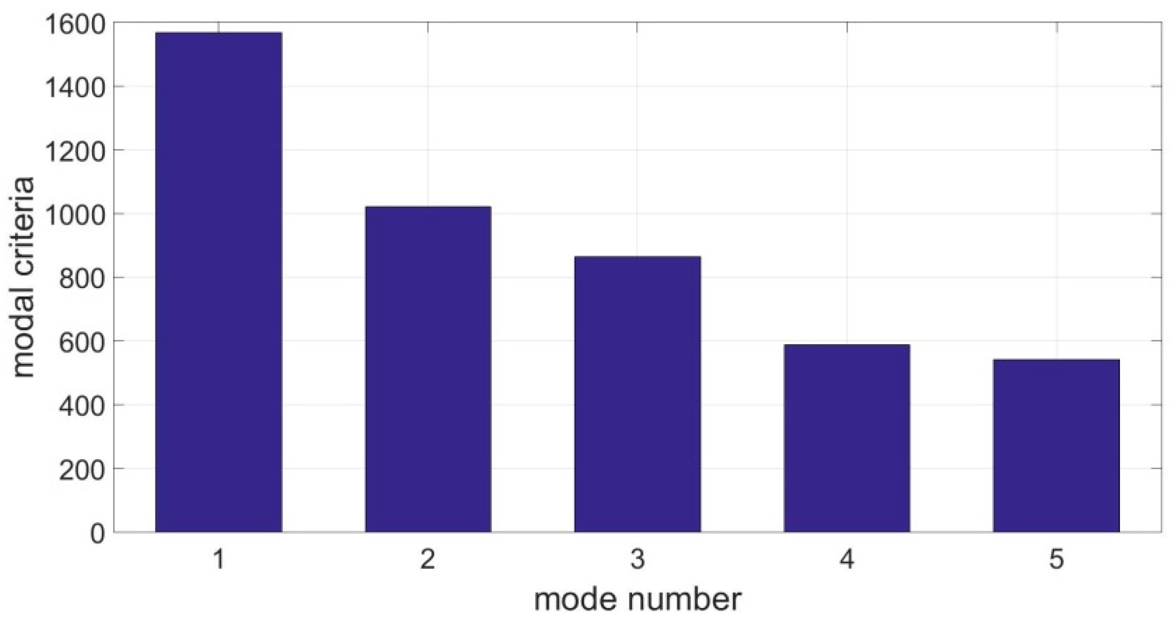
The modal criteria ηi of mode 1–5 are drawn in Figure 7, which shows that the modal criterion decreases with increasing mode number. Two transducers are used to control modes 1 and 2 because they possess higher values of modal criterion. For comparison, another strategy with mode 3 and 4 under control are also computed. The tuned RL values and added damping ratios calculated by complex modal analysis of the full mechano-electric finite element model (the size of the matrices [M], [D], [K] in (12) is 3770 × 3770) are listed in Table 2 and Table 3. The added damping ratios of different modes are distinct, because fraction of MSE of the rods in Figure 6a are distinct, as is shown in Figure 6b.
After generating the random excitation using inverse FFT technique, the Newmark-β method based on MATLAB code with time step Δt = 1/213 is employed to simulate the time-domain response. In order to observe the decrease of the resonance peaks, an observation point is set which is shown in Figure 2. The PSD of vertical response of this point in three conditions are illustrated in Figure 8. Obviously, when modes 1 and 2 are under control, the resonance peaks of modes 1 and 2 are declined considerably while other peaks remain unchanged. When modes 3 and 4 are under control, the only decreased peaks are 3 and 4.
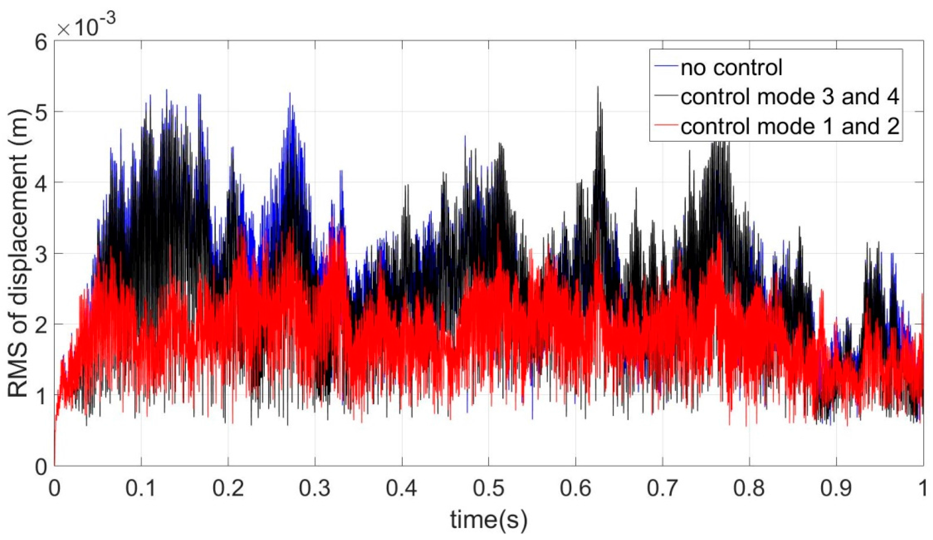
Finally, in order to validate the modal criterion proposed in this paper to suppress the overall transverse vibration of the face sheet, RMS vertical displacements of all the nodes in the face sheet, say, the H2 norm of vector {y} in expression (16), in different sampling time points are calculated in three conditions. The same realization of random excitation is used for convenience of comparison. The result is illustrated in Figure 9. It can be seen that the response of the structure without control (blue line) possesses highest value on the whole. The value of response with mode 3 and 4 controlled (black line) is slightly lower than the condition without control while the value of response with mode 1 and 2 controlled (red line) is lower than the other two conditions obviously. The time averages of RMS in three conditions are also computed: 0.2414 m/s (no control); 0.1727 m/s (control mode 1 and 2) and 0.2284 m/s (control mode 3 and 4).
6. Conclusions
In this article, an independent modal resonant shunt control method is used to suppress random spatial vibration of the face sheet of a Kagome truss core sandwich panel structure. First, the Kagome truss core sandwich panel is introduced, and the mechano-electric model of the structure with shunt circuits is established using the Lagrange–Maxwell equation. Next, an H2 norm sensitivity-based modal criterion is derived based on a state-space model, which depends on the modal H2 norm, modal damping ratio and fraction of MSE of the replaced rod. Finally, numerical simulation is employed and the effects of control strategies with different controlled modes are compared.
The result shows that the independent modal resonant shunt control method can suppress random vibration response of the face sheet by suppressing the resonance peaks with only a few piezoelectric transducers, and the proposed modal criterion can be used to determine which modes to control. This modal criterion is also expected to be used in other passive or active damping methods, such as viscous damping, viscoelastic damping, integral force feedback control, etc.
Acknowledgments
This work is supported by the National Natural Science Foundation of China (11502183), the Natural Science Foundation of Shaanxi Province (2016JM1021), and the Postdoctoral Science Foundation of China (2016M592750).
Author Contributions
Yalan Xu proposed the modal criterion; Kongming Guo performed the numerical study, analyzed the data and wrote the paper.
Conflicts of Interest
The authors declare no conflict of interest.
References
- Song, G.; Sethi, V.; Li, H.-N. Vibration control of civil structures using piezoceramic smart materials: A review. Eng. Struct. 2006, 28, 1513–1524. [Google Scholar] [CrossRef]
- Park, J.H.; Kim, W.H.; Shin, C.S. A comparative work on vibration control of a quarter car suspension system with two different magneto-rheological dampers. Smart Mater. Struct. 2017, 26, 015009. [Google Scholar] [CrossRef]
- Sinha, A. Optimal damped vibration absorber for narrow band random excitations: A mixed H2/H∞ optimization. Probab. Eng. Mech. 2009, 24, 251–254. [Google Scholar] [CrossRef]
- Tso, M.H.; Yuan, J.; Wong, W.O. Suppression of random vibration in flexible structures using a hybrid vibration absorber. J. Sound Vib. 2012, 331, 974–986. [Google Scholar] [CrossRef]
- Hagood, N.W.; Von Flotow, A. Damping of structural vibrations with piezoelectric materials and passive electrical network. J. Sound Vib. 1991, 146, 243–268. [Google Scholar] [CrossRef]
- Yan, B.; Zhang, X.; Luo, Y.; Zhang, Y. Negative impedance shunted electromagnetic absorber for broadband vibration absorbing: Experimental investigation. Smart Mater. Struct. 2014, 23, 125044. [Google Scholar] [CrossRef]
- Becker, J.; Fein, O.; Maess, M.; Gaul, L. Finite element-based analysis of shunted piezoelectric structures for vibration damping. Comput. Struct. 2006, 84, 2340–2350. [Google Scholar] [CrossRef]
- Wang, G.; Wang, J.; Chen, S.; Wen, J. Vibration attenuations induced by periodic arrays of piezoelectric patches connected by enhanced resonant shunting circuits. Smart Mater. Struct. 2011, 20, 125019. [Google Scholar] [CrossRef]
- Beck, B.S.; Cunefare, K.A.; Collet, M. The power output and efficiency of a negative capacitance shunt for vibration control of a flexural system. Smart Mater. Struct. 2013, 22, 065009. [Google Scholar] [CrossRef]
- Ji, H.; Qiu, J.; Cheng, J.; Inman, D. Application of a negative capacitance circuit in synchronized switch damping techniques for vibration suppression. J. Vib. Acoust. 2011, 133, 041015. [Google Scholar] [CrossRef]
- Moheimani, S.O.R.; Fleming, A.J. Piezoelectric Transducers for Vibration Control and Damping; Springer: Berlin, Germany, 2006. [Google Scholar]
- Wu, S.Y. Method for multiple mode shunt damping of structural vibration using a single PZT transducer. Proc. SPIE 1998, 3327, 159–168. [Google Scholar]
- Hollkamp, J.J. Multimodal passive vibration suppression with piezoelectric materials and resonant shunts. J. Intell. Mater. Syst. Struct. 1994, 5, 49–57. [Google Scholar] [CrossRef]
- Alessandroni, S.; dell'Isola, F.; Porfiri, M. A revival of electric analogs for vibrating mechanical systems aimed to their efficient control by PZT actuators. Int. J. Solids. Struct. 2001, 39, 5295–5324. [Google Scholar] [CrossRef]
- Guo, K.M.; Jiang, J. Independent modal resonant shunt for multimode vibration control of a truss-cored sandwich panel. Int. J. Dyn. Control 2014, 2, 326–334. [Google Scholar] [CrossRef]
- dos Santos e Lucato, S.L.; Wang, J.; McMeeking, R.M.; Evans, A.G. Design and demonstration of a high authority shape morphing structure. Int. J. Solids Struct. 2004, 41, 3521–3543. [Google Scholar] [CrossRef]
- Fang, Z.; Zheng, L. Topology optimization for minimizing the resonant response of plates with constrained layer damping treatment. Shock Vib. 2015, 2015, 376854. [Google Scholar] [CrossRef]
- Aridogan, U.; Basdogan, I. A review of active vibration and noise suppression of plate-like structures with piezoelectric transducers. J. Intell. Mater. Syst. Struct. 2015, 26, 1455–1476. [Google Scholar] [CrossRef]
- Guo, X.; Jiang, J. Passive vibration control of truss-cored sandwich plate with planar Kagome truss as one face plane. Sci. China Technol. Sci. 2011, 54, 1113–1120. [Google Scholar] [CrossRef]
- Guo, X.; Jiang, J. Optimization of actuator placement in a truss-cored sandwich plate with independent modal space control. Smart Mater. Struct. 2011, 20, 115011. [Google Scholar] [CrossRef]
- Preumont, A.; de Marneffe, B.; Deraemaeker, A.; Bossens, F. The damping of a truss structure with a piezoelectric transducer. Comput. Struct. 2008, 86, 227–239. [Google Scholar] [CrossRef]
- Thomas, O.; Ducarne, J.; Deü, J.-F. Performance of piezoelectric shunts for vibration reduction. Smart Mater. Struct. 2012, 21, 015008. [Google Scholar] [CrossRef]
- Gawronski, W.K. Advanced Structural Dynamics and Active Control of Structures; Springer: Berlin, Germany, 2004. [Google Scholar]
Figure 1.
Schematic representation of the Kagome structure. The solid face sheet (upper) is shown in dark grey, the truss core (middle) in grey and the planar Kagome truss (bottom) as one face plane in black.
Figure 1.
Schematic representation of the Kagome structure. The solid face sheet (upper) is shown in dark grey, the truss core (middle) in grey and the planar Kagome truss (bottom) as one face plane in black.

Figure 2.
Sketch of finite element model of (a) a Kagome structure, where the red arrow represents the observation point in Section 5; (b) the core truss; (c) the planar Kagome truss.
Figure 2.
Sketch of finite element model of (a) a Kagome structure, where the red arrow represents the observation point in Section 5; (b) the core truss; (c) the planar Kagome truss.
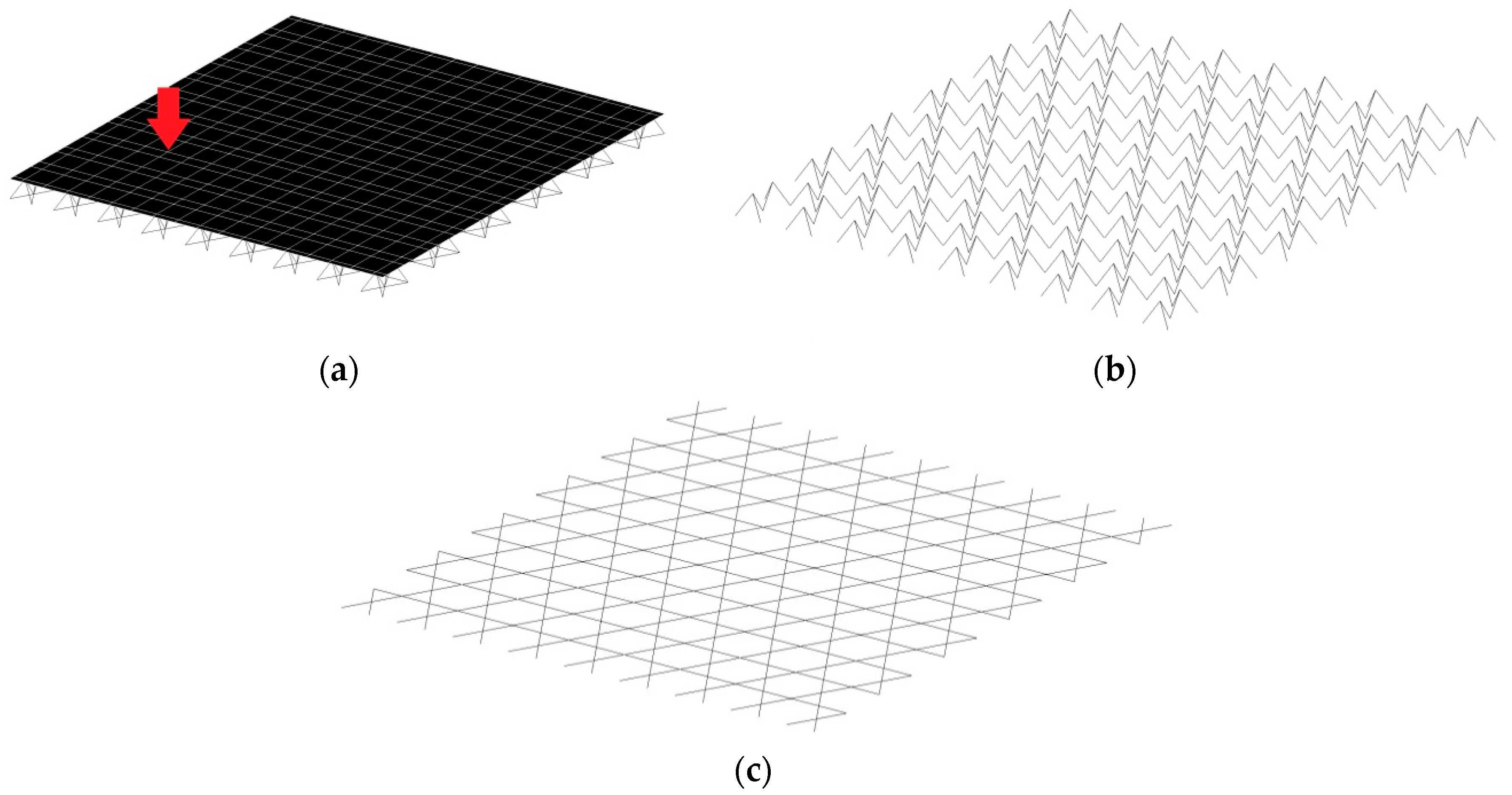
Figure 3.
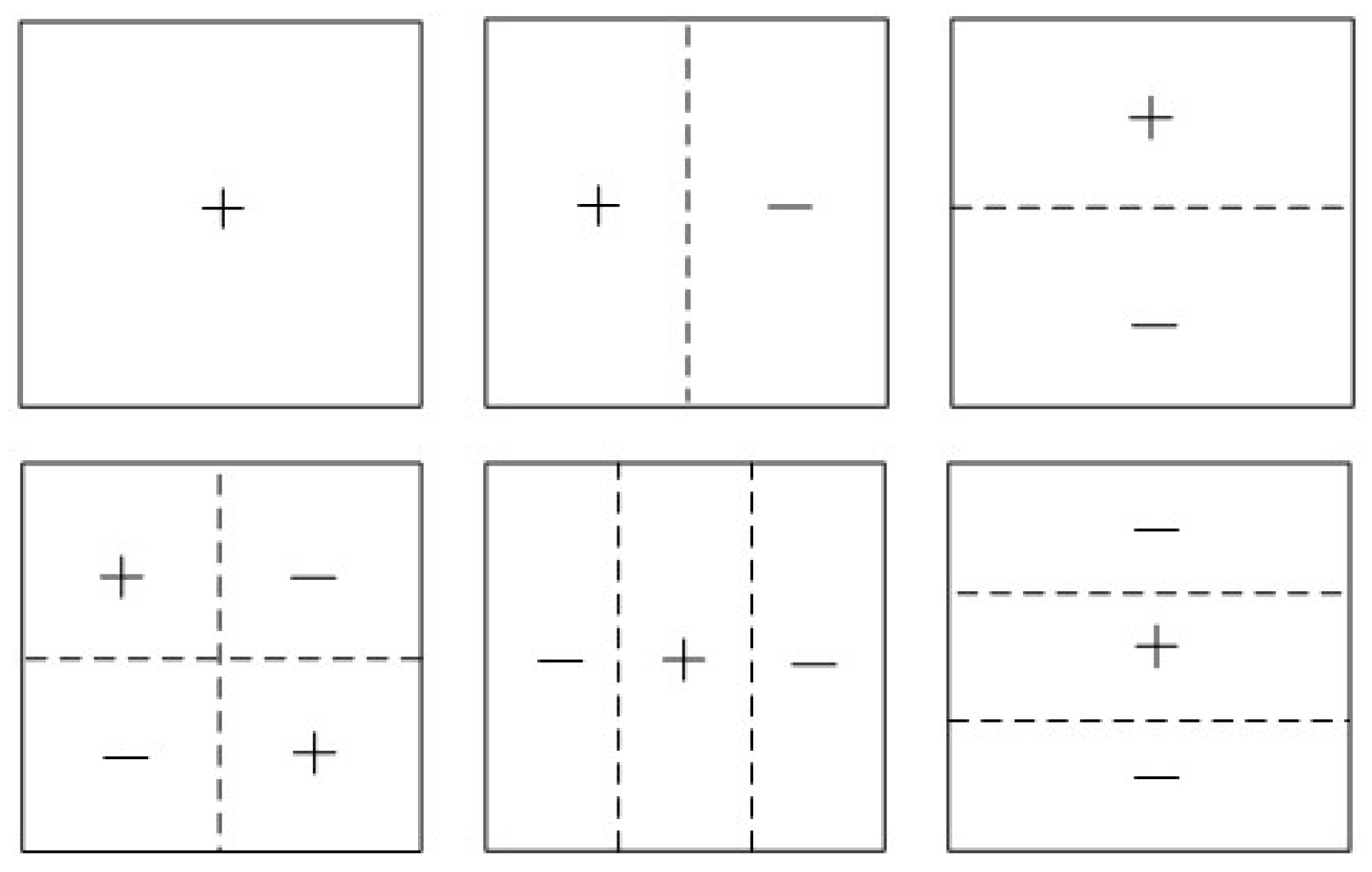
Mode shapes 1–6 with modal frequencies 297 Hz, 507 Hz, 550 Hz, 717 Hz, 775 Hz, 836 Hz, respectively.
Figure 3.
Mode shapes 1–6 with modal frequencies 297 Hz, 507 Hz, 550 Hz, 717 Hz, 775 Hz, 836 Hz, respectively.

Figure 4.
(a) Piezoelectric stack transducer; (b) Structure with one transducer and one resonant shunt circuit.
Figure 4.
(a) Piezoelectric stack transducer; (b) Structure with one transducer and one resonant shunt circuit.
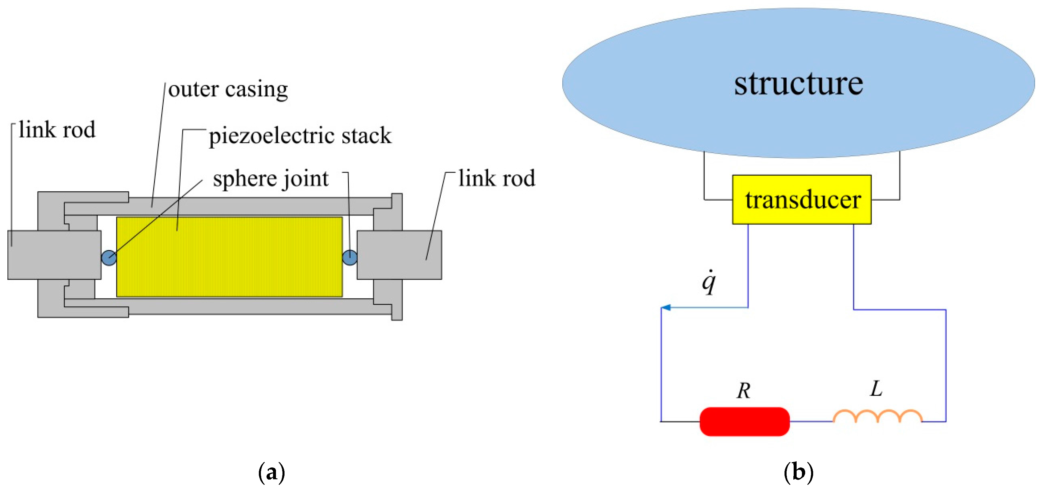
Figure 5.
Energy dissipation mechanism of mode i.
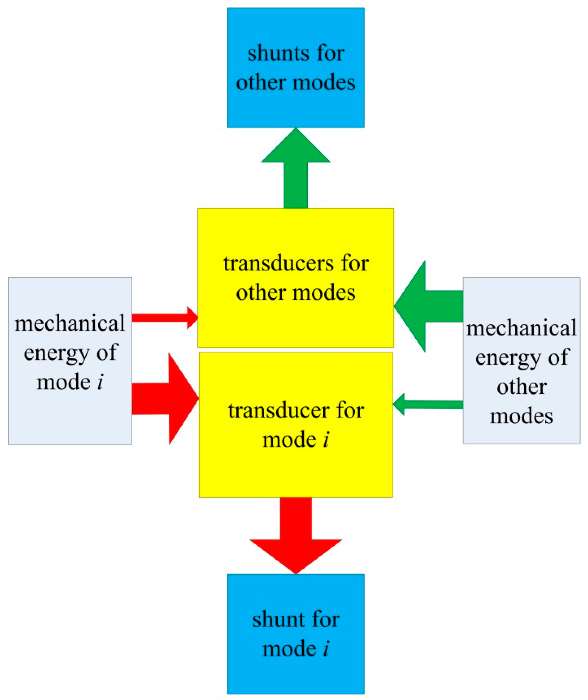
Figure 6.
(a) Locations of transducers for modes 1–5; (b) fraction of MSE in the replaced rods.

Figure 7.
Modal criterion of mode 1–5.

Figure 8.
Power spectral density (PSD) of responses of the observed point structure (a) without control (b) control mode 1–2 (c) control mode 3–4.
Figure 8.
Power spectral density (PSD) of responses of the observed point structure (a) without control (b) control mode 1–2 (c) control mode 3–4.
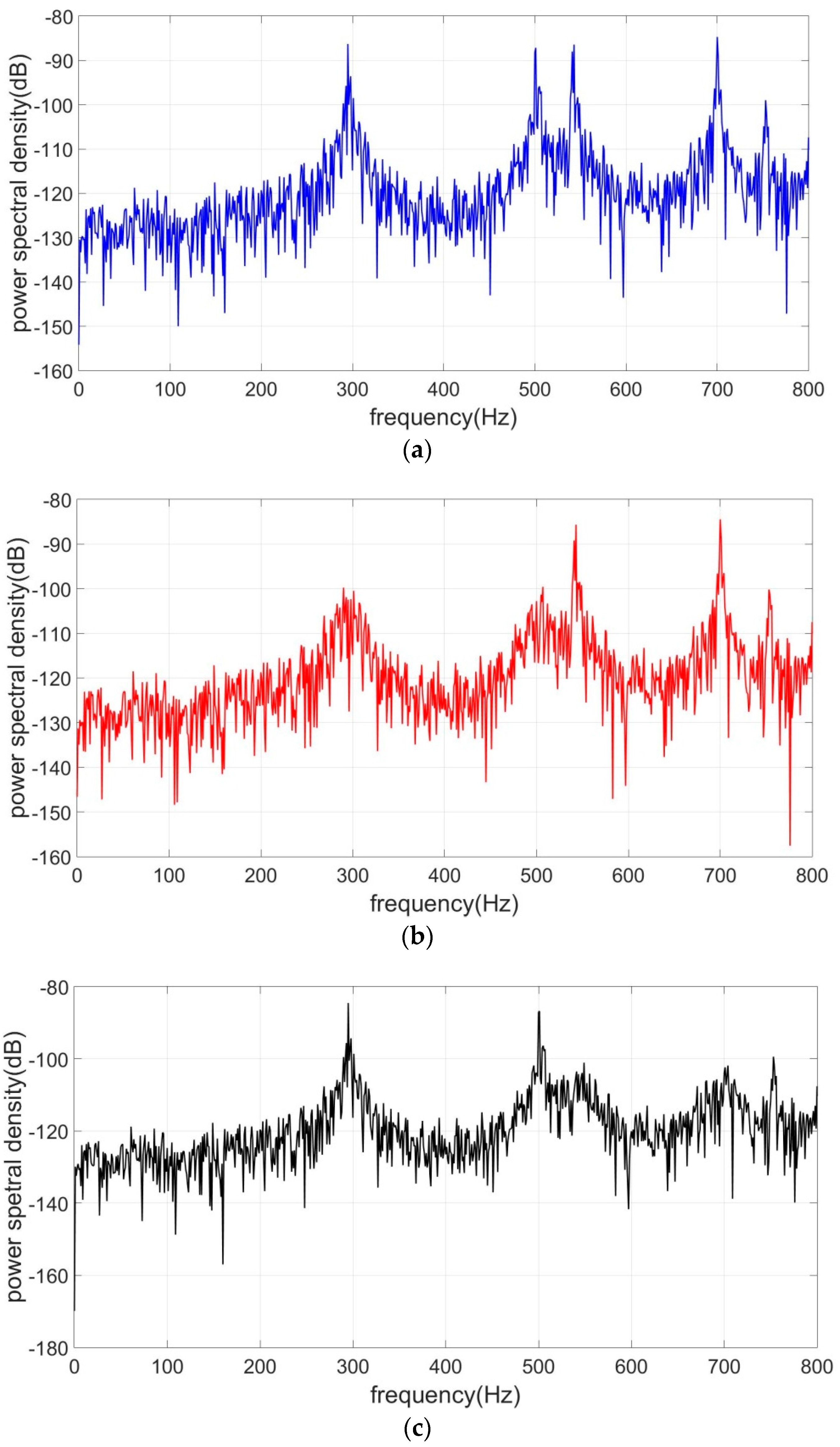
Figure 9.
Root mean square (RMS) vertical displacements of all the nodes in the face sheet in three conditions.
Figure 9.
Root mean square (RMS) vertical displacements of all the nodes in the face sheet in three conditions.


Table 1.
Material parameters, size of face sheet and truss rods.
| Face Sheet | Truss Rods | ||
|---|---|---|---|
| Material | Al alloy | Material | Steel |
| Young’s modulus | 73.1 GPa | Young’s modulus | 193 GPa |
| Density | 2700 kg/m3 | Density | 8030 kg/m3 |
| Length | 0.97 m | Rod Length | 51 mm |
| Width | 0.87 m | Section | Circle |
| Thickness | 1.53 mm | Radius | 1.275 mm |
Table 2.
Tuned RL values and added damping ratios for mode 1–2 when controlling mode 1–2.
| Mode | Resistance | Inductance | Added Damping Ratios |
|---|---|---|---|
| 1 | 515 Ω | 2.34 H | 0.029 |
| 2 | 266 Ω | 0.80 H | 0.024 |
Table 3.
Tuned RL values and added damping ratios for mode 3–4 when controlling mode 3–4.
| Mode | Resistance | Inductance | Added Damping Ratios |
|---|---|---|---|
| 3 | 204 Ω | 0.64 H | 0.021 |
| 4 | 145 Ω | 0.37 H | 0.019 |
© 2017 by the authors. Licensee MDPI, Basel, Switzerland. This article is an open access article distributed under the terms and conditions of the Creative Commons Attribution (CC BY) license (http://creativecommons.org/licenses/by/4.0/).
Share and Cite
MDPI and ACS Style
Guo, K.; Xu, Y. Random Vibration Suppression of a Truss Core Sandwich Panel Using Independent Modal Resonant Shunt and Modal Criterion. Appl. Sci. 2017, 7, 496. https://doi.org/10.3390/app7050496
AMA Style
Guo K, Xu Y. Random Vibration Suppression of a Truss Core Sandwich Panel Using Independent Modal Resonant Shunt and Modal Criterion. Applied Sciences. 2017; 7(5):496. https://doi.org/10.3390/app7050496
Chicago/Turabian StyleGuo, Kongming, and Yalan Xu. 2017. "Random Vibration Suppression of a Truss Core Sandwich Panel Using Independent Modal Resonant Shunt and Modal Criterion" Applied Sciences 7, no. 5: 496. https://doi.org/10.3390/app7050496
Note that from the first issue of 2016, this journal uses article numbers instead of page numbers. See further details here.