1. Introduction
With the increase in the use of electrical equipment, there is a possibility that high-power DC distribution systems will be needed, such as the 270 V DC power-supply system developed by More/All Electric Aircraft. If electrical power can be transmitted at a high voltage, resulting in low current and low conduction losses, the cable weight can be reduced. An investigation [
1] showed that the ±270 V DC power distribution system architecture is the most reliable configuration that can sustain an operation, even under severe supply transients [
2]. The 270 V DC electrical power is used primarily in military vehicles and military aircrafts. It is advantageous in terms of the ease of paralleling DC electrical bus bars and integration with loads such as actuators. To satisfy the growing demand for high-capacity short-circuit protection, several methods that interrupt direct currents have been extended [
3,
4,
5,
6]. Forced current zero (FCZ) is a common method used to interrupt the DC current. This method for DC interruption forces the current to zero by injecting a high-frequency current of the opposite polarity [
7]. In the FCZ method, an oscillating current is generated by the resonance of a precharged capacitor and an inductor, and by superimposing this oscillating current over the current in the main circuit, a current zero is produced. Thus, the burning arc in the vacuum interrupter (VI) [
8] can be extinguished by the FCZ. Then, the breaker in the main circuit can successfully interrupt the DC current [
9,
10]. A successful interruption is significantly influenced by the transient characteristics of the current-commutation process, such as the rates of the current and voltage at zero-crossing (|
di/
dt| and |
dv/
dt|). To reduce the size and cost of the forced-commutation branch, a high frequency is usually selected for the commutation branch. However, this condition is unfavorable for the recovery of dielectric strength, as well as for the thermal interruption capability of the VI after current zero [
11]. Thus, an optimal design for the forced-commutation branch is important. It is known that the transient characteristics are influenced by the commutating capacitor, commutating inductor, precharged voltage, etc. As these parameters may demonstrate coupling effects, the apparent relationships among the transient characteristics and the parameters of the forced-commutation branch are mostly worthy of investigation, during the design.
Since VIs have excellent insulating and arc-quenching capabilities, the vacuum circuit breaker is often used as the main circuit breaker for DC interruption. Substantial research has been carried out on the axial magnetic field (AMF) contacts, based on FCZ. It is suggested that, when the current falls to zero very rapidly during DC interruption, the vacuum arc characteristics mainly depend on the characteristics before the instant of the countercurrent injection. However, the AMF has an inhibiting effect on the initial expansion stage. The vacuum arc is constricted by the magnetic field, while the arc columns in the butt electrodes expand much faster [
12]. The AMF VI can maintain the diffusion of ions and electrons to the entire electrode; however, it is harmful for deionization [
13].
The structure of the vacuum circuit breaker contact has been of paramount importance for vacuum arc modes and successful current interruptions. Two different versions of transverse magnetic field (TMF) contacts are being used—spiral-type and cup-shaped contacts. Schneider patented the spiral design in the USA in the late 1950s [
14], and the cup-shaped design was patented by Lake and Reece in the early 1960s [
15]. Several previous papers [
16,
17,
18,
19,
20,
21,
22,
23] have dealt with the investigation of the behavioral patterns of vacuum arcs on TMF and butt contacts at line frequencies (50 Hz). The interrupting ability of VI has been proven for currents up to several tens of kiloamperes, using TMF contacts, and until now, much research has been done on the TMF contacts at line frequencies and intermediate frequencies [
24]. A constricted electric arc formed at higher currents is forced into motion by a self-induced magnetic field created by the breaking current, to reduce local overheating and severe erosion on the contact surface [
25]. Very limited amounts of research work have been conducted on vacuum arcs with TMF contacts applied to FCZ vacuum circuit breakers. This paper focuses on the arc behaviors during the DC-arcing stage, the breaking performance influenced by the arc behavior, and the breaking capacity with different contact materials and arcing times, for spiral-type contacts under FCZ in aero applications. It is expected to provide a theoretical basis for industrial applications.
Based on the FCZ vacuum circuit breakers used in aviation DC power-supply systems, the transient characteristics of DC forced interruption are analyzed, using both theory and simulations. The theoretical calculations for di/dt are obtained by defining the reverse peak-current coefficient k. The characteristics of VI voltage during interruption are researched through simulations. The results can provide guidance for the experimental scheme and vacuum circuit breaker design. In order to research the vacuum arc behavior and breaking performance of the spiral-type VI, experiments are conducted with different contact materials, arcing times, and current ratings. The appearances of the vacuum arc in the designed TMF contacts are observed using high-speed photography, in the case of currents less than 3.5 kA. The arc re-ignition is analyzed based on the obtained arc appearances, and the breaking capacities with different arcing times are obtained experimentally. Finally, the influences of arc behavior and arcing time on the current interruption performance are discussed.
2. Transient Characteristics of DC Forced Interruption
2.1. DC Interrupion Scheme and Simulation Model
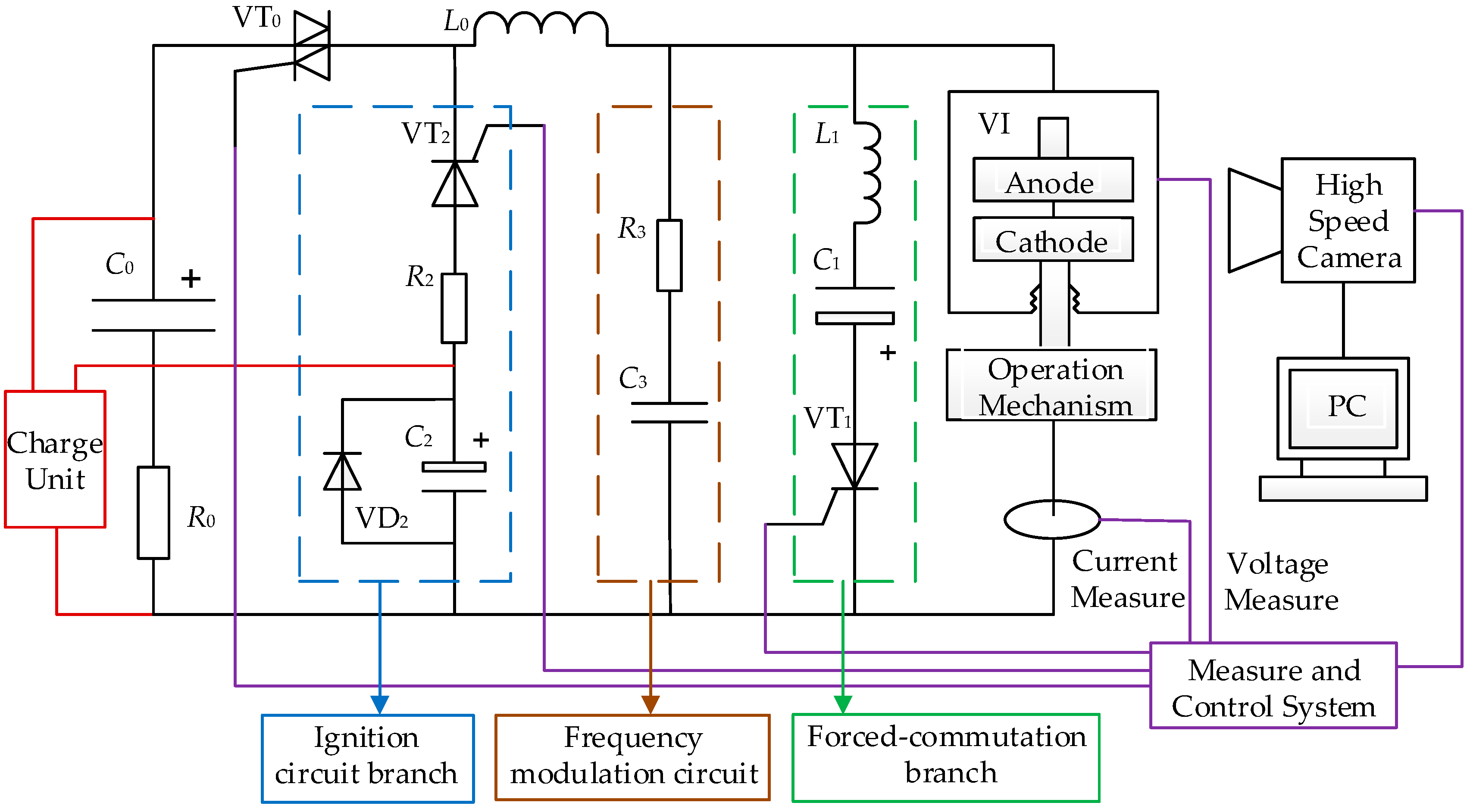
The most well-known DC vacuum circuit-breaker scheme has a forced-commutation branch connected in parallel to a VI; the DC forced interruption schematic is shown in
Figure 1. The forced-commutation branch contains a precharged commutating capacitor
C1, a commutating inductor
L1, and a thyristor
VT1. The capacitor polarity is chosen such that the first capacitor discharge current wave
IC is in the direction opposite to that of the arc current
IA in the VI. If the amplitude of the commutating capacitor current
IC exceeds that of the main circuit,
I0, the arc current in the VI goes through zero, and the current is interrupted. After the interruption, the polarity of the commutating capacitor
C1 is reversed to the primary polarity. The
RC frequency-modulation circuit composed by
R3 and
C3 has two functions. First, the capacitor in the
RC branch, whose capacitance is much higher than the stray capacitance of the VI, can uniformly distribute the transient recovery voltage across the break of each interruption. Second, the resistor in the
RC branch can dampen the high-frequency oscillations in the transient recovery voltage, and can consequently suppress the rising rate of the transient recovery voltage [
11].
Based on the forced-commutation interruption, a simulation model is established using MATLAB/Simulink. The main circuit breaker VI is set as an ideal switch, and the contact resistance is ignored when the switch is closed. The ideal switch is closed in the DC-arcing stage, and different currents are obtained by adjusting the resistance R0. At the beginning of the simulation, the ideal switch is closed, and the thyristor VT1 is triggered in the forced-commutation branch after a delay of 1 ms. The current flowing through the main circuit breaker decreases, and when the current is less than a preset value, the ideal switch is opened. In the forced-commutation branch in the simulation model, L1 is set as 3.4 μH and C1 is 1620 μF. The frequency-modulation circuit consists of a resistor R3 and capacitor C3, with values of 0.1 Ω and 0.1 μF, respectively. The L0, which has a value of 12 μH, is the stray inductance generated during accrual situations.
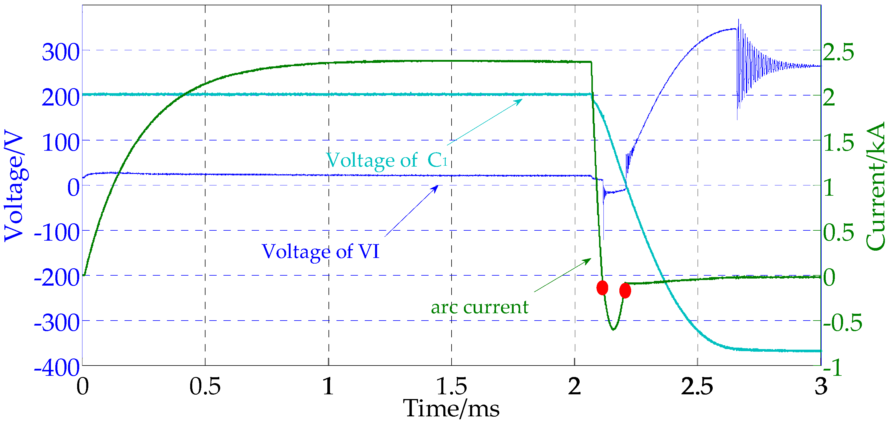
2.2. Direct-Current Forced Interruption Process
From the typical waveforms of DC forced interruption, shown in
Figure 2, it can be observed that the interruption process consists of three stages: the DC-arcing stage, current-commutation stage, and voltage-recovery stage. The DC-arcing stage occurs from the beginning of the simulation to the beginning of the forced-commutation-branch conduction. In this stage, the current through the ideal switch is constant. When the thyristor
VT1 is trigged, the second stage—the current-commutation stage—begins. The arc current
IA decreases rapidly by virtue of the current commutation to the forced-commutation branch. After this, the voltage of the VI starts decreasing within several microseconds, and the VI voltage starts oscillating at a high frequency. From then, the main circuit current
I0 begins to decrease, and the voltage-recovery stage begins. The voltage between the contacts of VI increases. This process is actually the reverse charging process of the capacitor, which ends when the contact voltage reaches the power-supply voltage.
2.3. di/dt in Current-Commutation Stage
di/
dt and
dv/
dt are important parameters in the current-commutation stage. We calculate
di/
dt as the average current-change rate over the time from the start of forced commutation to the current zero condition, and
dv/
dt as the average voltage-change rate over the time from the current zero condition to the first peak of the recovery voltage [
26].
In the current-commutation stage, when the arc resistance is ignored, the commutating current
IC can be approximated as per the following equation:
where
; the reverse peak current is shown in Equation (2):
The reverse peak-current coefficient
k is set by the equation:
i0 is the main circuit current.
U0 is the precharged voltage of the commutating capacitor in the forced-commutation branch, which should satisfy:
As the arc current decreases approximately linearly in the current-commutation stage in
Figure 2,
di/
dt is calculated using the following equation [
27]:
where
L is the inductance of the commutating inductor in the forced-commutation branch. As can be seen from Equation (5), when the forced-commutation branch parameters are certain,
di/
dt can be reduced through the appropriate reduction of the precharged voltage. Similarly, when
U0 and
C are fixed, the increase of
L is beneficial to the reduction of
di/
dt. In fact, the above two methods to reduce
di/
dt lead to the reduction of the reverse peak current in Equation (2). It can be concluded that the magnitude of
di/
dt is directly related to the reverse peak-current coefficient, when the main circuit current
I0 is fixed. The selection of the charging margin directly affects the value of
di/
dt. When the circuit parameters are determined, the precharged voltage
U0 is determined by the value of
k, which affects the transient characteristics in the interruption process. Substituting Equation (4) into Equation (5), we obtain Equation (6), as follows:
If the decay of the oscillation current in the current-commutation stage is ignored,
di/
dt can be determined from the oscillation frequency and the coefficient
k under the same breaking current level. Under the same oscillation frequency, the selection of the reverse peak-current coefficient
k directly determines the value of
di/
dt. In order to ensure reliable commutation, the value of
k is generally chosen to be between 1.3 and 2. In practical applications, in order to calculate the
di/
dt in the current-commutation stage accurately, the following formula is used:
Here, , , , and R is the equivalent stray resistance in the forced-commutation branch, which is 22 mΩ in our research.
Table 1 shows the comparisons of the
di/
dt obtained through the methods of Formulation (7), simulation, and experiments. The results calculated using Equation (7) are in good agreement with the simulation and experimental results.
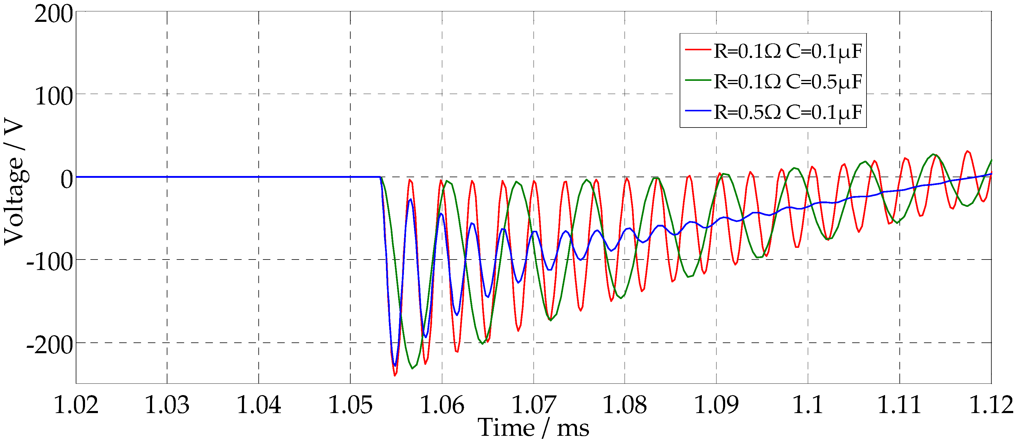
2.4. Voltage Transient Characteristics in Forced-Commutation Interruption
The voltages in the current-commutation stage demonstrate two types of waveforms with different frequencies. Only the low-frequency vibrations are determined by inductance
L1. There are two high-frequency oscillations. The first high frequency is influenced by the frequency-modulation circuit and the forced-commutation branch. When the parameters in the forced-commutation branch are fixed,
dv/
dt is determined by the
R and
C in the frequency-modulation circuit alone, in the current-commutation stage. The voltage of the VI in the current-commutation stage for different frequency-modulation circuit parameters is shown in
Figure 3. It is suggested that the decreased value of
C3 will lead to a rise in
dv/
dt and in the oscillation frequency. The change in
R3 does not affect the slope of
dv/
dt, but it affects the oscillation amplitude. When the circuit is not connected parallel to the frequency-modulation circuit, the transient recovery voltage is mainly influenced by the capacitance
C of the forced-commutation branch and the main circuit current
i0 [
28].
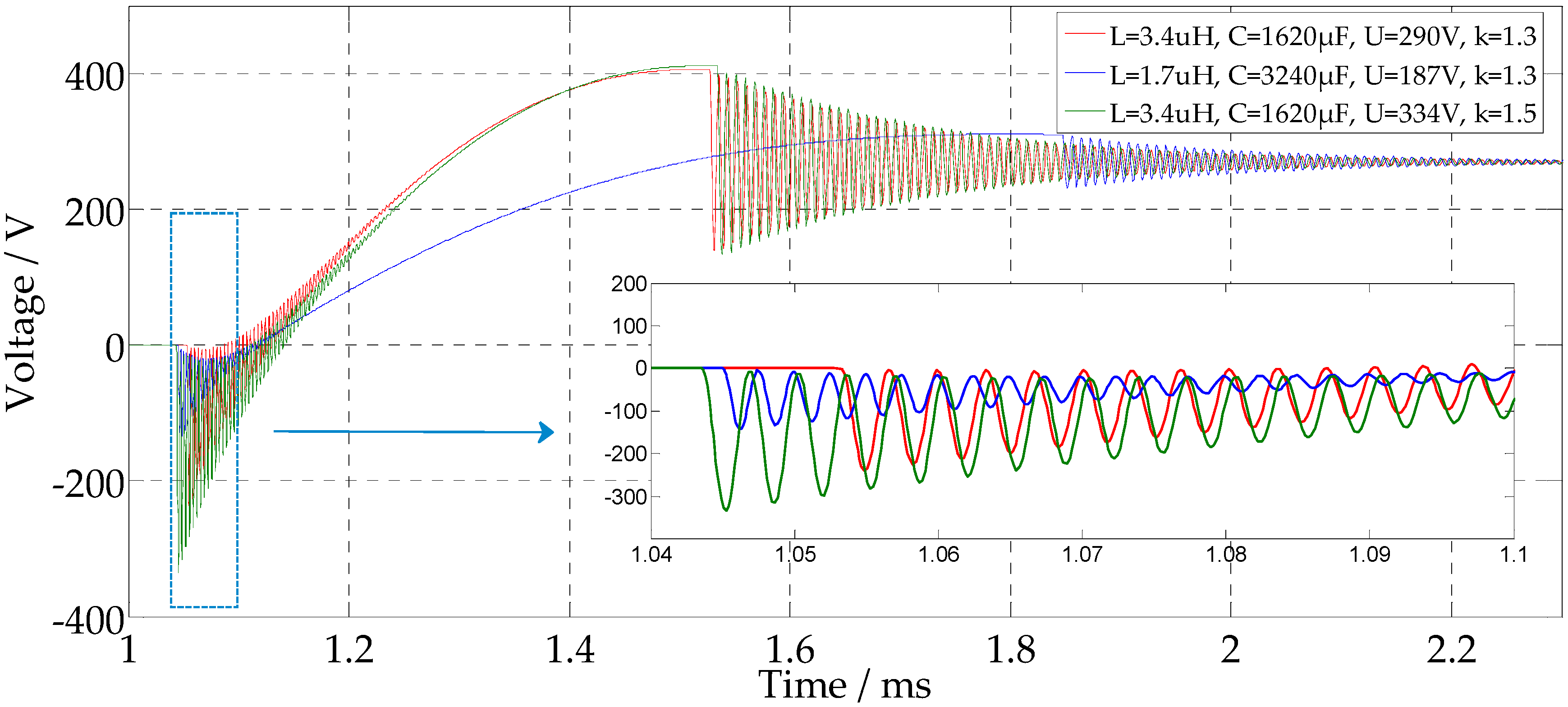
The frequency of the second high-frequency oscillation is influenced by the frequency-modulation circuit and the inductance
L0 in the main circuit. The oscillation amplitude is determined by the breaking current
I0, the residual voltage in
C1, and the
L1. By changing the parameters of the forced-commutation branch, the change in VI voltage can be obtained through simulations, as shown in
Figure 4. By comparing the three simulation conditions and results, we can observe that, when the inductance of the commutation inductor is halved and the capacitance of the commutation capacitor is doubled, the commutation frequency remains unchanged, and the peak value of the VI voltage will be lower. With an increase in the commutation capacitance, the commencement of the voltage oscillations is delayed, but the three interruptions shown in
Figure 4 end at the same time. This is due to the reduction in the precharged voltage of the commutation capacitor by the smaller inductance under the same
k. The increased capacitance leads to a delay in the start of oscillation, but dampens the oscillation amplitude and period. Furthermore, with a smaller commutation inductance, the amplitude and period of the VI voltage can be effectively suppressed in the two oscillation processes. Besides, when
k is set to be larger, the voltage increases with a higher precharged voltage of
C1.
From the above analysis, it can be inferred that the selection of the reverse peak-current coefficient k affects not only the di/dt in the current-commutation process, but also the VI voltage transient characteristics in interruption. Properly reducing the value of k can reduce the slope of di/dt and lead to better voltage transient characteristics. When designing the parameters of the forced-commutation branch, the coupling relationships among the parameters should be comprehensively considered. The use of a power-supply voltage of 270 V limits the overvoltage during interruption to a much smaller value, by setting the absorption branch. Therefore, the precharged voltage of the commutation capacitor should be less than the peak of the overvoltage, to reduce the withstanding voltage of the forcing capacitor; thereby, the volume and cost can be reduced. With the decrease in L/C, the precharged voltage of the capacitor can also be reduced effectively, and the peak value of the VI voltage can be reduced under the same oscillation frequency.
3. Experimental System Setup
A direct circuit system was used to study the DC forced-commutation interruption, as shown in
Figure 5. The instantaneous short-circuit current was supplied from the capacitor
C0 with the capacitance value of 2 F, by triggering the bidirectional thyristor
VT0 controlled by the measure-and-control system. The main current ratings were obtained by adjusting
R0. In the breaking cycle, the experimental results showed that the total attenuation of the circuit current was less than 10%, which could provide a stable short-circuit current. As the contact separation time was uncertain, the time of arc ignition was also uncertain; thus, the arcing time was incorrect. An ignition circuit branch was designed to ignite the arc before the main current was injected. When contact separation occurred, an arc was formed between the anode and the cathode in the VI. At this time, the VI current was small, as long as the arc could be maintained, until the contacts were fully open. This current was provided by
VT2,
C2, and
R2. The branch of
R3 and
C3 was composed as a frequency-modulation circuit. The frequency-modulation circuit was used to guarantee the same rate of rise of recovery voltage parameters after interruption. The forced-commutation branch included
VT1,
C1, and
R1. The amplitude of the oscillation current was determined by the main circuit current
I0 and the reverse peak-current coefficient
k. The arc voltage and arc current were recorded by a multichannel isolated oscilloscope. The arc voltage was obtained from the voltage drop across the VI, and was corrected for the induced voltage drop caused by the resistance of the VI. The arc current was measured using a Roche Coil. A Phantom v7.3 high-speed video camera and a PC were used to record the arc appearances and the arc moving processes with a camera sample rate of 72,000 frames/s and exposure time of 1 μs. The parameters of the experimental system for DC forced interruption are listed in
Table 2.
The detailed experimental operation is shown in
Figure 6, and is described below. At the start of the experiment, the charging voltage of the capacitor
C0 is 270 V, and the precharged voltage of the capacitor
C2 is approximately 200 V. The precharged voltage of
C1 varies according to the current rating of the arc current. The VI is in the closed position at this time. The trigger thyristor
VT2 is triggered first to ignite the direct current, followed by the opening of the contacts, and a vacuum arc is maintained with a small current of approximately 80 A until the contacts are fully open. The opening of the contacts is actuated by the operation mechanism signal. Then, the camera signal and the thyristor
VT0 are triggered sequentially. The direct current is injected and the DC-arcing stage begins.
VT2 is switched off by the negative voltage. After the arcing time, the thyristor
VT1 is triggered, and the forced-commutation process occurs.
Specially designed sealed VIs with spiral-type TMF contacts for forced-commutation interruption are utilized in the experimental system, as shown in
Figure 7. The parameters of the electrodes are listed in
Table 3. In order to observe the vacuum-arc appearance, the normally present metal shield of the VI is removed.
5. Discussion
Low-current diffuse-type intensive arcs with highly evaporative cathode roots are mainly formed at the edges of the contacts and slots. At the position of a particularly intensive cathode spot, this can result from the continued heating of the localized hot area of the anode [
30]. This also influences the density of the metal vapor at current zero. The thermal hysteresis will maintain a hot cathode surface for some time. Even though the current decline rate is very fast, the hot cathode continues to emit plasma for some time [
31]. As a result, when the transient recovery voltage is increased, breakdown occurs and interruption fails. Meanwhile, local overheating would not only cause major contact erosion, but also reduce the breaking capacity because of the increased metal vapor generation and the pronounced afterglow effect [
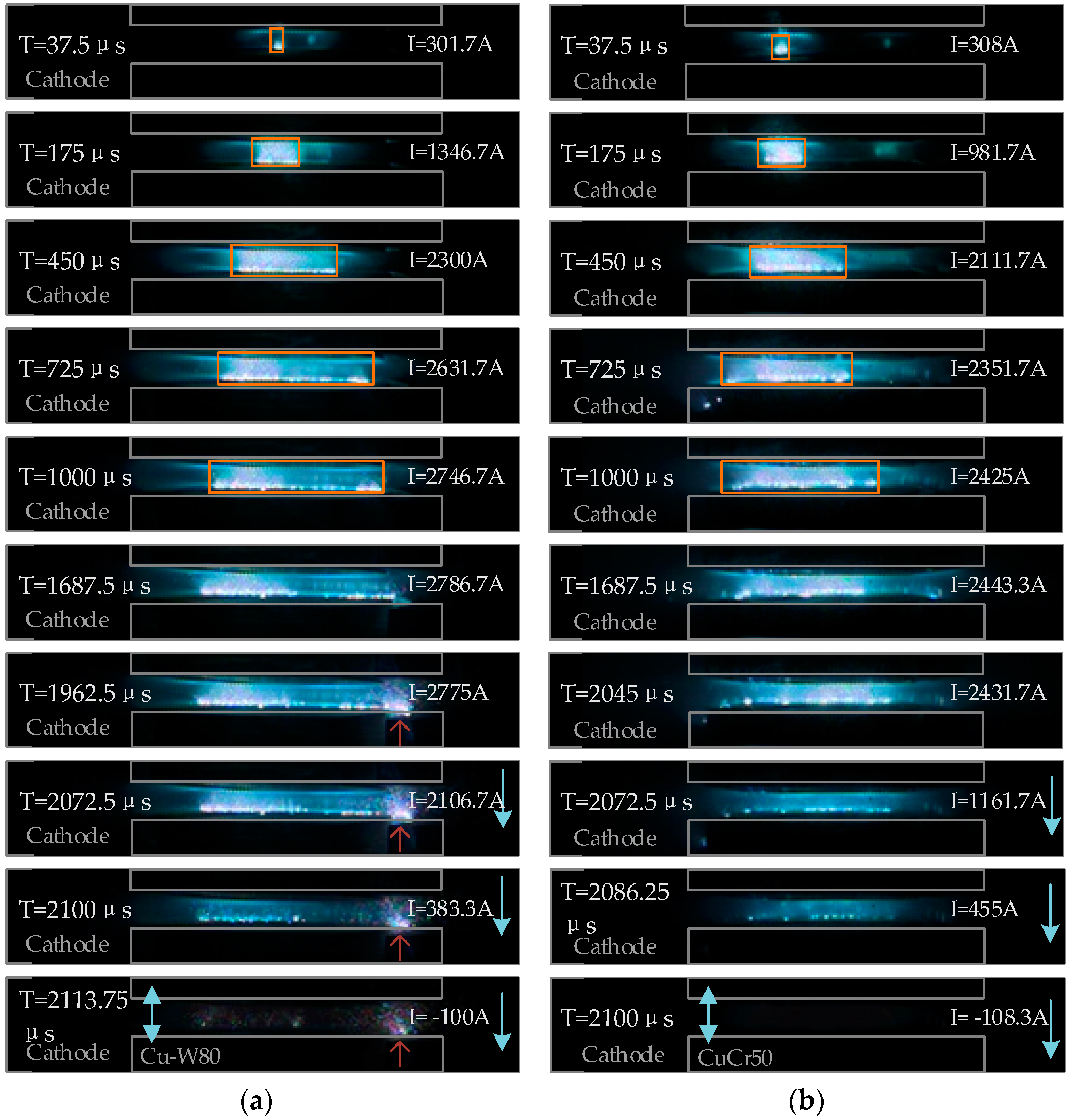
32]. Once the intensive arc has developed, the arc root moves slowly and more plasma is emitted to the gap. At the position of the intensive arc, the amount of residual metal vapor is much more when the arc current passes through zero. Hence, the probability of re-ignition increases and the breaking capacity reduces.
On comparing the arc appearances of the two types of contacts, no intensive arc mode is observed in the CuCr50 contact. As we know, the melting and boiling points of CuW80 are much higher than that of CuCr50, for which the arc and cathode surface temperatures are higher in the type A contact. Thus, the extinguishment and movement of cathode spots are impeded, which causes the arc to burn continuously at the local region. Therefore, it can be inferred that the occurrence of an intensive arc mode is related to the contact material, and that the possibility is greater for a high-melting-point contact material. Besides, in [
33], it is noted that severe erosion occurs at both the anode and the cathode under the intensive arc mode, and that the intensive arc mode tends to occur at shorter gap lengths.
At the arc root, the charge carriers collide with the contact surface and transfer energy to the contact [
21]. The total arcing energy can be calculated from the measured arc voltage, arc current, and arcing time, and can be expressed as follows:
where
Parc is the mean power input (in Watts),
Warc is the arc energy (in Joules),
tarc is the arcing time,
Rarc is the arc resistance, and
Iarc is the arc direct current (in Amperes). In the DC-arcing stage, the arc current and arc voltage change by small amounts. According to Equation (9), the arcing energy is affected by the arcing duration
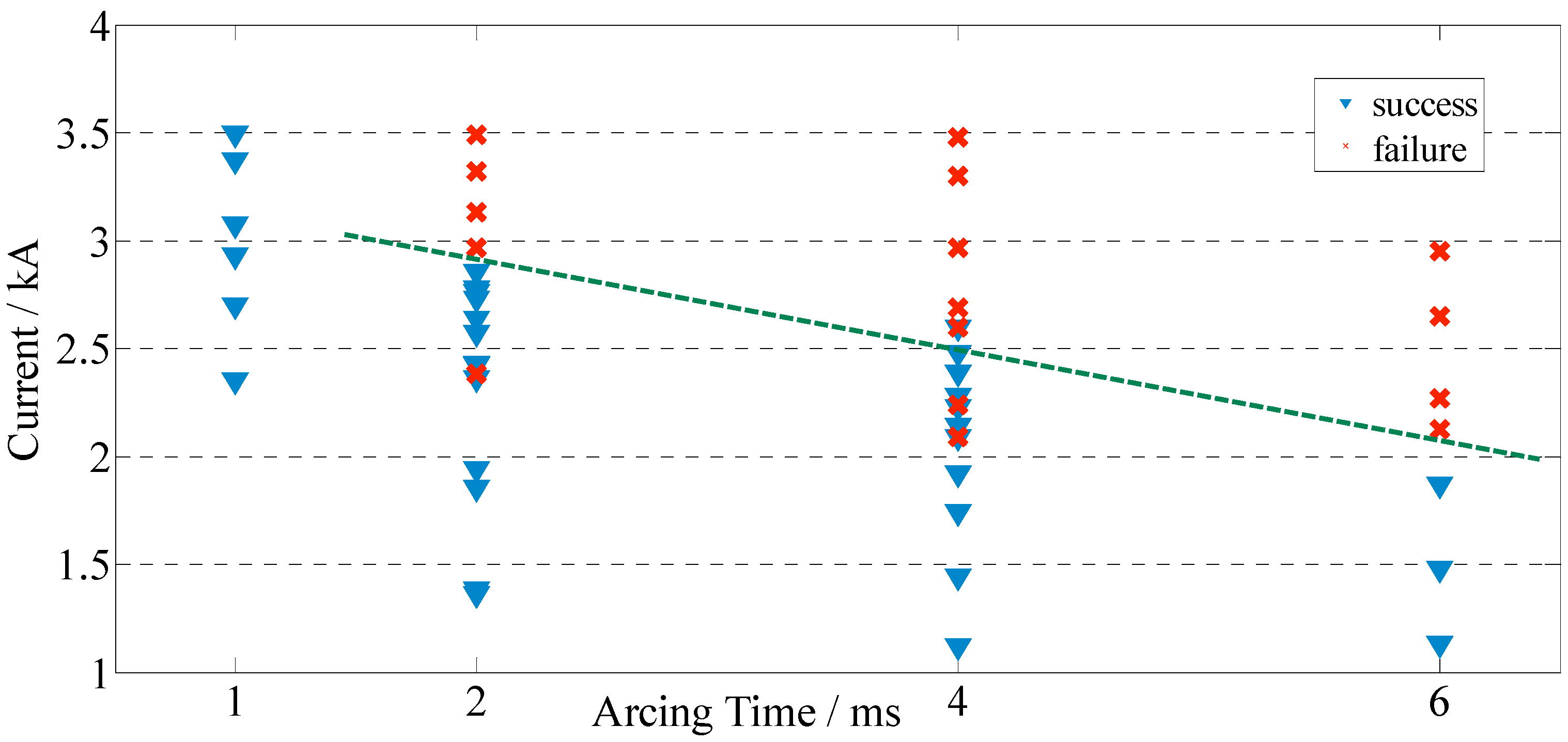
tarc, proportionally. With a long arcing time, the DC-arcing stage is prolonged, and more energy is input to the contact. The energy transferred to the contact is mainly expended as heat conduction into the contact and evaporative cooling, which leads to higher temperatures on the contact surface. This may be a necessary condition for the occurrence of the intensive burning arc. The intensive arc mode only develops if the arcing time is long enough. Besides, the amount of residual metal vapor in the gap distance is more with a longer arcing time than with a shorter arcing time, leading to a high metal vapor density, weak dielectric strength, low breakdown voltage, and long recovery time. Therefore, a long arcing time is detrimental for the recovery of dielectric strength after current zero [
9].
6. Conclusions
Based on the method of FCZ, the transient characteristics and breaking performances of spiral-type TMF contacts were researched, for aero applications. The experimental and analysis results obtained from the simulations of the interruption processes and experiments under different conditions are summarized below.
The selection of the reverse peak-current coefficient k affected not only the di/dt in the commutation process, but also the VI voltage characteristics in the recovery process. Properly reducing the value of k could reduce the slope of di/dt and lead to better voltage characteristics. By decreasing L/C, the pre-charging voltage of the capacitor could be reduced effectively, and the peak value of the VI voltage could be reduced.
Low-current diffuse-type intensive arcs with highly evaporative cathode roots were mainly formed at the edges of the contacts and slots. The intensive arc mode increased the probability of re-ignition and reduced the breaking capacity of the VI. The position of re-ignition was the region of intensive arcing. The occurrence of the intensive arc mode was related to the contact material, and the possibility was greater for high-melting-point contact materials.
The best breaking performance was observed for an arcing time of 1 ms in the CuW80 contact. If the arcing time was longer than 1 ms, the breaking performance deteriorated, and the breaking ability became proportional to the arcing time.


