
Energy Regeneration Hydraulic System via a Relief Valve with Energy Regeneration Unit
by
Tianliang Lin
1, 
Qiang Chen
1,
Haoling Ren
1,2,*,
Yi Zhao
1,
Cheng Miao
1,
Shengjie Fu
1 and
Qihuai Chen
1,2 1
College of Mechanical Engineering and Automation, Huaqiao University, Xiamen 361021, China
2
State Key Laboratory of Fluid Power and Mechatronic Systems, Zhejiang University, Hangzhou 310027, China
*
Author to whom correspondence should be addressed.
Appl. Sci. 2017, 7(6), 613; https://doi.org/10.3390/app7060613
Submission received: 21 April 2017
/
Revised: 9 June 2017
/
Accepted: 9 June 2017
/
Published: 13 June 2017
(This article belongs to the Special Issue Power Transmission and Control in Power and Vehicle Machineries)
Abstract
:Featured Application
This research aims to reduce the energy loss through the relief valve, especially in the systems where the system pressure is high or the overflow flow rate is large.
Abstract
Relief valves are widely used in industrial machinery. Due to the outlet of the relief valve being connected to the tank, the pressure drop of the relief valve is frequently equal to the inlet pressure. Accordingly, the energy loss of the relief valve is very high in some cases and this will worsen with an increase in the rated pressure of the hydraulic system. In order to overcome the disadvantage of overflow energy loss in a relief valve, a hydraulic energy regeneration unit (HERU) is connected to the outlet of the relief valve to decrease the pressure drop between the inlet and outlet of the relief valve. The overflow loss, which is characterized by the pressure drop, can be reduced accordingly. The approach is to convert the overflow energy loss in hydraulic form and allow for release when needed. The configuration and working principle of the relief valve with HERU is introduced in this present study. The mathematical model is established to obtain the factors influencing the stability of the relief valve. The working pressure of the hydraulic accumulator (HA) is explored. Furthermore, the control process of the operating state of the HA is scheduled to decide whether to regenerate the energy via the HERU. The software AMESim is utilized to analyze the performance and characteristics of the relief valve with HERU. Following this, the test rig is built and used to verify the effectiveness of the proposed relief valve with HERU. The experimental results show that the relief valve with the HERU connected to its outlet can still achieve better pressure-regulating characteristics. The energy regeneration efficiency saved by the HA is up to 83.6%, with a higher pre-charge pressure of the HA. This indicates that the proposed structure of the relief valve with HERU can achieve a better performance and higher regeneration efficiency.
1. Introduction
The energy crisis and new emissions rules have motivated the development of new proposals for energy efficient vehicles and non-road mobile machines. Construction machinery, especially the hydraulic excavator (HE), is widely used in transport and infrastructure, which can output a larger amount of power and consume a larger proportion of energy. Therefore, the energy saving and regeneration become the research hotspot to reduce the energy consumption and emissions [1,2,3,4,5]. The energy loss of the hydraulic system can be divided into two types: throttling loss and overflow loss.
Research examining energy saving in fluid power systems has mainly concentrated on reducing the throttling loss. There are few studies focusing on reducing the energy loss in relief valve. The objective of systems, such as the positive/negative flow control system [6,7], load sensing control [8] and separate control of actuator ports [9], is to match the pump supply to the demands of load. Hence, the throttle energy loss can be reduced to some extent. Furthermore, the pump controlled system has been widely applied [10,11,12]. One of the most significant merits of the pump controlled system is that the energy regeneration system (ERS) becomes efficient. However, the overflow loss through the relief valve due to the frequent start-stop function and rotary, such as the swing of a hydraulic excavator, still exists and consumes a large amount of energy [13]. Furthermore, there are few studies examining this loss. The recent fast digital valve development provided the groundwork for a wide variety of solutions and the digital valve can be used as the flow control valve to reduce the throttle energy loss [14]. However, the high speed on-off valve control system can avoid the overflow loss in the relief valve. Shi et al provided a hydropneumatic transformer to supply high-pressure oil to drive the vehicles, the efficiency of which can be improved by 10% [15].
Furthermore, there are studies on energy regeneration to save and reutilize the throttle energy produced by the potential energy of the boom. Wang et al. also presented an electric ERS, which integrates the regeneration device with the throttle valve using a different controller [16,17]. Using the pressure compensation principle, the electromagnetic torque of the generator was adapted to the loaded pressure. Therefore, the pressure drop across the throttle was guaranteed to remain a small constant pressure drop and consequently, the velocity of the boom cylinder can be regulated effectively by controlling the throttle valve opening. Furthermore, most of the throttle energy can be regenerated by the hydraulic motor and an electric motor.
Relief valves, the most important component in hydraulic systems, are widely used in industrial machinery. In hydraulic systems, the outlet of the relief valve is frequently connected to the tank and thus, the pressure loss of the relief valve, which is characterized by the inlet and outlet pressure, is equal to the inlet pressure. With an increase in the inlet pressure of the relief valve, the pressure loss increases accordingly. Therefore, the energy loss of the relief valve, which is the product of the flow rate and the inlet pressure, is very high and it will worsen with an increase in the rated pressure of the hydraulic system. If the energy through the relief valve can be saved and reutilized, the efficiency of the hydraulic system will be greatly improved.
This paper focuses on exploring the methods of regenerating the energy through the relief valve and the performance of the relief valve with the energy regeneration unit. The following part is organized as follows: The structure and working principle of the pilot relief valve (PRV) with the hydraulic energy regeneration unit (HERU) is proposed in Section 2. The mathematical model is developed and the control flow for the HA is presented in Section 3. The key parameters and control for the best working ability of the hydraulic accumulator (HA) to achieve the maximum energy saving are discussed in Section 4. After this, the experiment is carried out to verify the feasibility and the influence of the HERU on the PRV in Section 5. Following this, the concluding remarks are summarized in Section 6.
2. Configuration of the PRV with HERU
2.1. Configuration of HERU of Energy Loss in Relief Valve
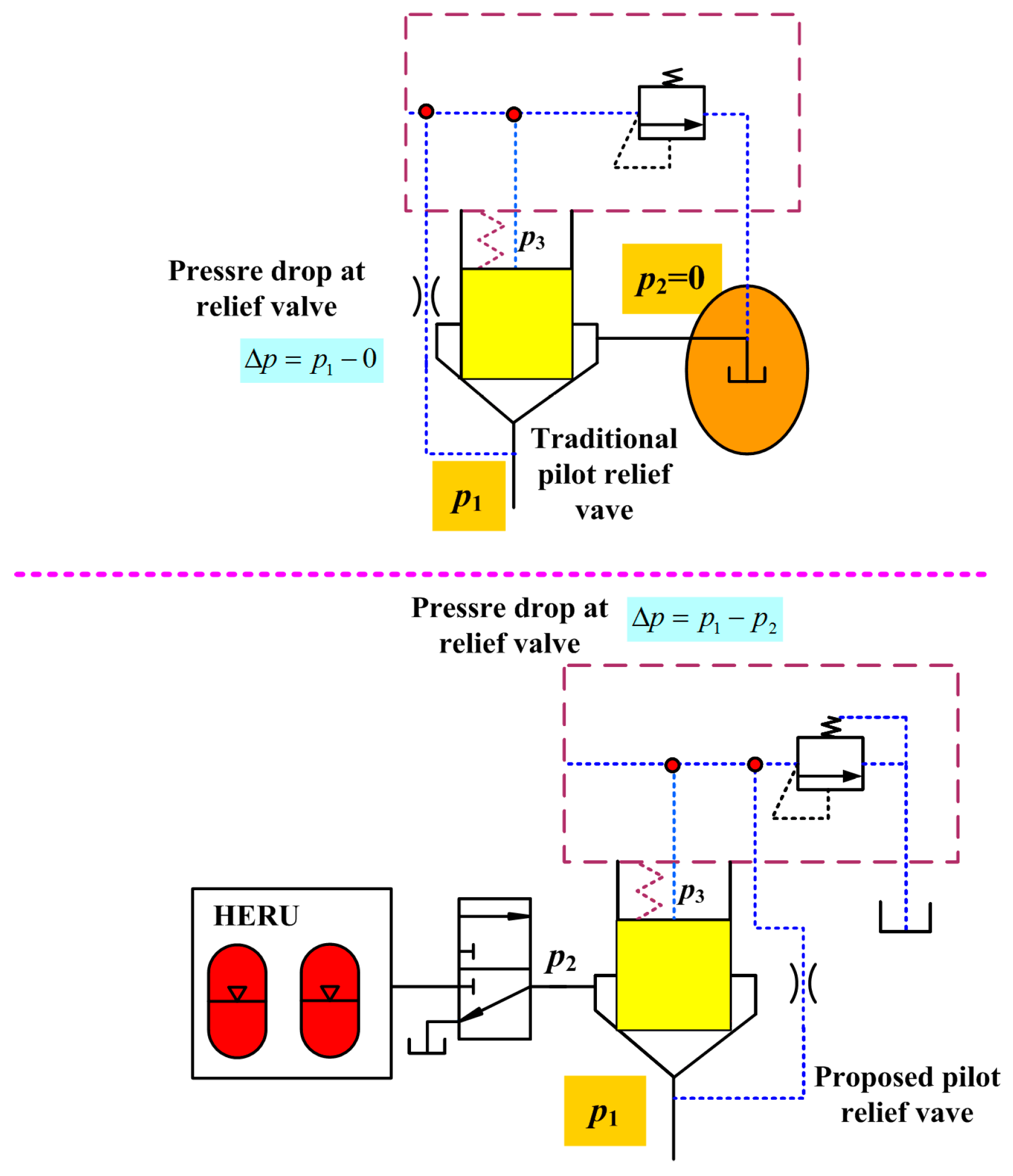
To reduce the energy loss of the relief valve, a hydraulic energy regeneration unit (HERU) is connected to the outlet of the relief valve, which can increase the outlet pressure of the relief valve and thus reduce the pressure drop between the inlet and outlet [18], as shown in Figure 1. As there are many types of relief valves, the PRV is chosen as an example in this paper. The advantages are as follows:
(1) The overflow energy loss, which backs into the tank directly in the traditional PRV, is converted into hydraulic energy to be stored in the HA and released when needed. During this process, the outlet pressure of the PRV is far higher than that of the tank, which means that the pressure drop between the inlet and outlet is decreased. Therefore, the pressure drop through the PRV can be reduced. The pressure drop of the PRV is defined as
where p1 is the inlet pressure of the PRV; p2 is the outlet pressure of the PRV; and Δp is the pressure drop between the inlet and outlet.
When the traditional PRV is connected to the tank, the pressure p2 is approximately equal to zero. Therefore, the pressure drop can be simplified as
When the HERU is connected to the outlet of the PRV, the oil will flow into the HERU and cause an increase in the outlet pressure p2. Therefore, the pressure p2 is far larger than zero, while the pressure drop through the PPRV is smaller than that without HERS.
The overflow energy loss in PRV is featured by the product of the flow rate and the pressure drop
where P is the power lost through the PRV and Q is the flow rate through the PRV.
The flow rate Q through the PRV remains mostly constant. Hence, the energy loss through the PRV with HERU is less than the traditional PRV. Moreover, the energy stored in the HERU can be reutilized and the efficiency of the hydraulic system can be improved. In general, a higher outlet pressure p2 results in a lower overflow energy loss of the PRV, which is characterized by the pressure drop ∆p. To ensure the normal operation of the PRV, the outlet pressure p2, which is caused by the HERU, must be smaller than the target relief pressure of the PRV.
(2) The proposed PRV is different to the traditional PRV in that the outlet of the pilot valve is connected to the tank alone. In comparison, the outlet of the pilot is connected to the outlet of the main valve in the traditional PRV. This difference can ensure that the pilot valve of the proposed PRV is not affected by the pressure fluctuations in the outlet of the PRV.
(3) As seen in Figure 1, the PRV has a main valve and a pilot valve. The inlet pressure p1 acts on the main valve spool and the pilot valve spool at the same time. Meanwhile, the pressure p3 of the spring chamber is also connected to the pilot valve spool. The outlet port of the PRV is connected to the HERU through a directional valve, which is used to determine whether to recover the overflow energy or not. The pilot oil circuit is connected to the tank alone to avoid an increase in the relief pressure as the PRV and the HERU are in series.
2.2. Working Principles of the PRV
Figure 2 is the working principle diagram of a PRV. The rated pressure of the PRV is set by the pilot operated proportional valve. A and B denote the inlet and outlet of the PRV, respectively. Back pressure in port B is produced by the HERU 5, which is connected to port B of the PRV.
When the adjusting spring of the pilot valve is pre-compressed to some extent, the relief pressure of the PRV is set. The system pressure is equal to the relief pressure of the PRV. The oil supplied to the PRV is divided into three parts: one acts on the bottom of the main valve spool, the second on the upper of the main valve spool and the third acts on the pilot valve. The latter two are supplied through orifice 2 in the main valve spool. The pilot spool remains closed and no oil flows through it when the force produced by the pressure p3 in the spring chamber 6 is less than the electromagnetic force. The main spool is also closed because the inlet pressure p1, which is equal to the pressure p3 in this case, is smaller than the resultant of the spring force and the pressure p3. The forces on the main spool satisfy the equation
where F0 is the pre-tightening force of the reset spring; A1 is the effective cross-sectional area of the main spool; and p3 is the pressure of the spring chamber.
The main spool continues closing until the inlet pressure is higher than the spring force of the pilot valve. At this time, the pilot valve is open and the pressure p3 is smaller than the inlet pressure p1 because there is a pressure drop across the orifice 2. Due to the small stiffness of the reset spring, the forces on the main spool satisfy the equation
Therefore, the main valve opens and the main valve spool moves upwards to allow the liquid to flow through port A to port B and then through HERU to the tank. The pressure in the HA of the HERU increases, while the pressure drop between the inlet and outlet of the main valve reduces. Following this, the overflow energy loss of the PRV decreases accordingly.
When the pre-compression of the spring of the pilot valve changes, the relief pressure changes accordingly. Furthermore, when the pressure of the HA changes, the performance of the PRV may be influenced. The influence of the HERU should be discussed to ensure a stable performance of the PRV and obtain a comparable, better control characteristic.
3. Control System
The control system has two goals. One is to recycle as much of the overflow energy as possible using the HERU. The other is to guarantee the operation characteristics of the PRV with the HERU. In other words, the PRV can still control the pressure of the system despite having an HERU, which is connected to the outlet of the PPRV. Therefore, how to choose the parameters of the HERU and how to control these parameters during the energy regeneration process are essential considerations for the control system.
3.1. Working Pressure of the HA
The HA is the main component of the HERU and must be properly designed to achieve the two goals of the control system. The key parameters of the HA include the rated volume, the pre-charge pressure, as well as the minimum and maximum working pressure. The appropriate parameters of the HA are beneficial in controlling how much energy can be regenerated. For example, if the working pressure of the HA is high, which means that the outlet pressure of the PRV is high, the pressure drop of PRV is consequently small and the energy lost in the orifice is low. However, the amount of oil that the HA can store is less. In comparison, if the working pressure of the HA is low, which means that the outlet pressure of the PRV is low, the energy lost in the orifice of the PRV is subsequently high. However, the amount of oil that the HA can store is more.
The HA is ideal for those confronted with frequent and short start-stop cycles in adequate space. The key advantage of using HA as energy regeneration components in HERU is its seamless interface. They can be easily integrated into a hydraulic circuit of a HE. However, the major disadvantage of a HA is that the energy storage density is severely limited compared to other competing technologies, such as the battery. Therefore, the major objective of working pressure optimization for the HA is to improve the energy density of the HA.
According to the Boyle’s law, the gas in the accumulator follows the ideal gas law as
where pa0 is the pre-charge pressure of HA; Va0 is the rated volume of HA; Va1 and pa1 are the gas volume and pressure when the HA is at the minimum working pressure, respectively; Va2 and pa2 are the gas volume and pressure when the HA is at the maximum working pressure, respectively; n is the polytrophic exponent; and C is a constant.
The HA used in the HE mainly functions during the starting and braking process, which lasts only a short period of time, while the working cycle of the HE is about 20 s. Following this, the compression process when the HA is charged can be considered as the adiabatic process. The gas index n is set to 1.4.
The volume of the HA is calculated by the equation
where ∆Va1 is the maximum oil volume that is stored in HA when the pressure in HA increases from pa1 to pa2.
The energy density of the HA can be calculated as
where
As seen from the above equations, increasing the volume of the HA, improving the pre-charge pressure and the maximum working pressure or reducing the minimum working pressure can improve the energy storage. The volume of the HA is constrained by the installation space of the HE. Furthermore, the pre-charge pressure, minimum and maximum pressure all are related to one another. In order to obtain the relationships, the derivative of Equation (8) is used as
Accordingly, the maximum energy density based on the optimum pressure ratio can be represented in the form
On the other hand, the HA works frequently in the process of charging and releasing. To prolong the service life of the HA, the peak volume change of the air bladder of the HA cannot be too large. Hence, the pressures should satisfy
0.25pa2 < pa0 < 0.9pa1
For example, if the rated pressure of the PRV is 21.5 MPa, the pressure drop of the PRV should be at least 1 MPa, which is the same as the pressure drop in the throttle control valve. This is needed to guarantee the fact that the PRV can release the redundant flow of the hydraulic system. Then, according to the pressure scope of the HE, the pressures of the HA can be chosen as
pa1 = 6.2 MPa
pa2 = 20 MPa
pa0 = 5 MPa
3.2. Control Flow
In an energy regeneration system for the energy loss of a PRV, the decision whether to regenerate the overflow energy depends on the relationships of the inlet/outlet pressure of the PRV and the maximum working pressure of the HA. Figure 3 shows the principle diagram of the tested PRV with a HERU connected to its outlet. The overload protection unit is used to protect the pump 4 when the PRV does not work. When the valve 1 is powered off, the regulating pressure of safety valve 2 is 31.5 MPa to ensure that no oil flows through valve 2 when PRV is working. In comparison, when the PRV does not work, valve 1 is powered to allow oil to flow from the pump to the tank with a low energy loss.
The flow meters 8, 12, and 13 are used to detect the flow rate in and out of the PRV. Pressure sensors 10, 11, 19, and 20 are used to gain the pressures of the pump, the inlet and outlet of the PRV and the HA. These pressures are used to determine the energy recovery process. In Figure 3, ps is the outlet pressure of the pump and pa is the pressure of the HA. The detailed control process is shown in Figure 4. The control strategy is based on following logic:
• Energy recovery mode
When the pressures satisfy pa < pa2, the PRV works in the energy recovery mode. In this condition, the valve 1 is powered off and the lower electromagnet of the valve 14 is powered on to make the valve 14 work at the bottom position. The overflow energy through the PRV will be stored in the HA until it reaches the maximum working pressure.
• Traditional mode
When the pressures satisfy pa ≥ pa2, the PRV works in the traditional mode. In this condition, valve 1 is powered on and both the electromagnets of valve 14 are powered off. The pump is unloaded through the safety valve 2, which is unloaded by valve 1. The valve 14 works at top position, while the HA is disconnected to the outside and the pressure is kept constant.
4. Simulation Results
Figure 5 is the simulation model built in AMESim based on the principle diagram and control flow shown in Figure 3 and Figure 4. The simulation model is used to test the influence of the HERU on the characteristics of the PRV and the influence of the pre-charge pressure on the energy regenerating efficiency of the HERU.
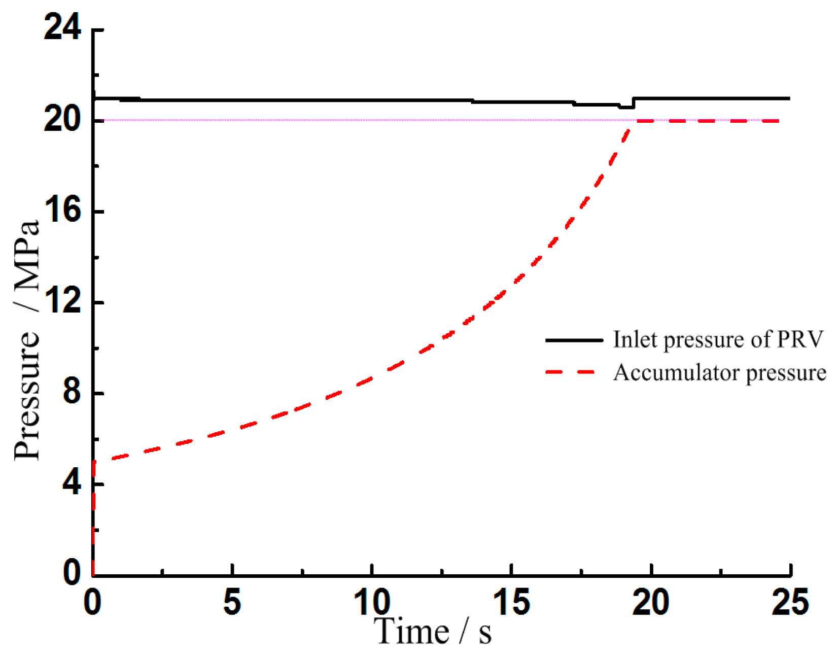
Figure 6 shows the inlet pressure of the PRV and the inlet pressure of the HA during the energy regenerating process. The pre-charge pressure of the HA is 5 MPa and the regulating pressure of the PRV is 20 MPa. As seen in Figure 6, with an increase in the regenerated energy in the HA, the pressure of the HA increases until it reaches its target value of 20 MPa. At the same time, the inlet pressure of the PRV decreases marginally from 21 MPa to 20.6 MPa. As the inlet of the HA is connected to the outlet of PRV, the pressure drop across the orifice of the PRV is 0.6 MPa. This indicates that the PRV can still maintain good performance under a lower pressure drop. It can also be deduced that the HERU that is connected to the outlet of the PRV has little influence on the performance of the PRV. The PRV can still control the system pressure steadily.
During the energy regeneration, the outlet pressure p2 of the PRV is nearly equal to the HA pressure pa. It is shown in Figure 6 and Figure 7 that with an increase in the outlet pressure p2 of the PRV, the displacement of the main valve spool increases to keep the flow rate constant. Hence, the flow rate of the PPV is maintained at a certain value is important so that the PPV can release the redundant flow of hydraulic system. The reason is that the displacement of the main valve spool will change according to the outlet pressure of the PRV, which is shown in Figure 7.
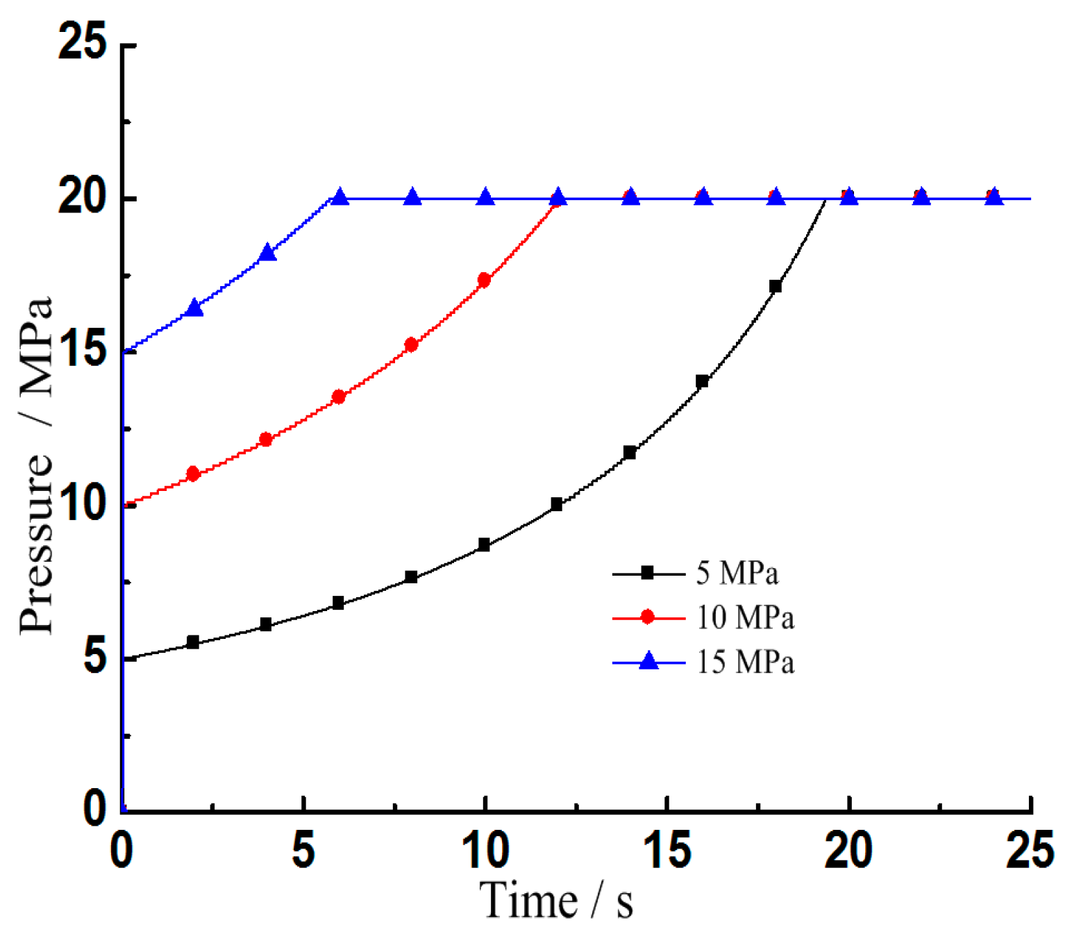
Figure 8 shows the compression of the pre-charge pressure on the charging process of the HA. The pre-charge pressure is 5, 10, and 15 MPa, respectively. When the energy regeneration starts, the pressure of the HA increases from the pre-charge pressure to its target value. During this process, the volume of HA remains the same. It can be seen that a higher pre-charge pressure results in a shorter time needed to reach the target pressure, which also means that less energy can be stored.
Figure 9 shows the influence of the outlet pressure of the PRV on the inlet pressure of the PRV. The regulation pressure of the PRV is set to 21.5 MPa. Before the PRV is powered on at the time of 1 s, the inlet pressure is slightly higher than the outlet pressure. After the PRV is powered on, the inlet pressure decreases a little with an increase in the outlet pressure, but the inlet pressure remains around 21.5 MPa, which is the regulating pressure of the PRV. The maximum pressure difference is 0.7 MPa, which is under 3.3% of the regulating pressure of the PRV. This indicates that the HERU connected to the outlet of the PRV has little influence on the pressure regulation characteristics.
5. Experimental Study and Discussion
5.1. Test Rig
The test rig was built to verify the characteristics of PRV with HERU. Figure 10 is the layout of the tested unit, according to the working diagram shown in Figure 3. The hydraulic pump can maximally supply a flow rate of 250 L/min under a maximum pressure of 31.5 MPa. The HERU includes a few HAs with different volumes, as shown in Figure 10. The PRV is the cartridge valve. The rated flow of the check valve and the directional valve is sufficient at 200 L/min, which can minimize the pressure drop during the test.
5.2. Results and Discussion
5.2.1. Control Performance
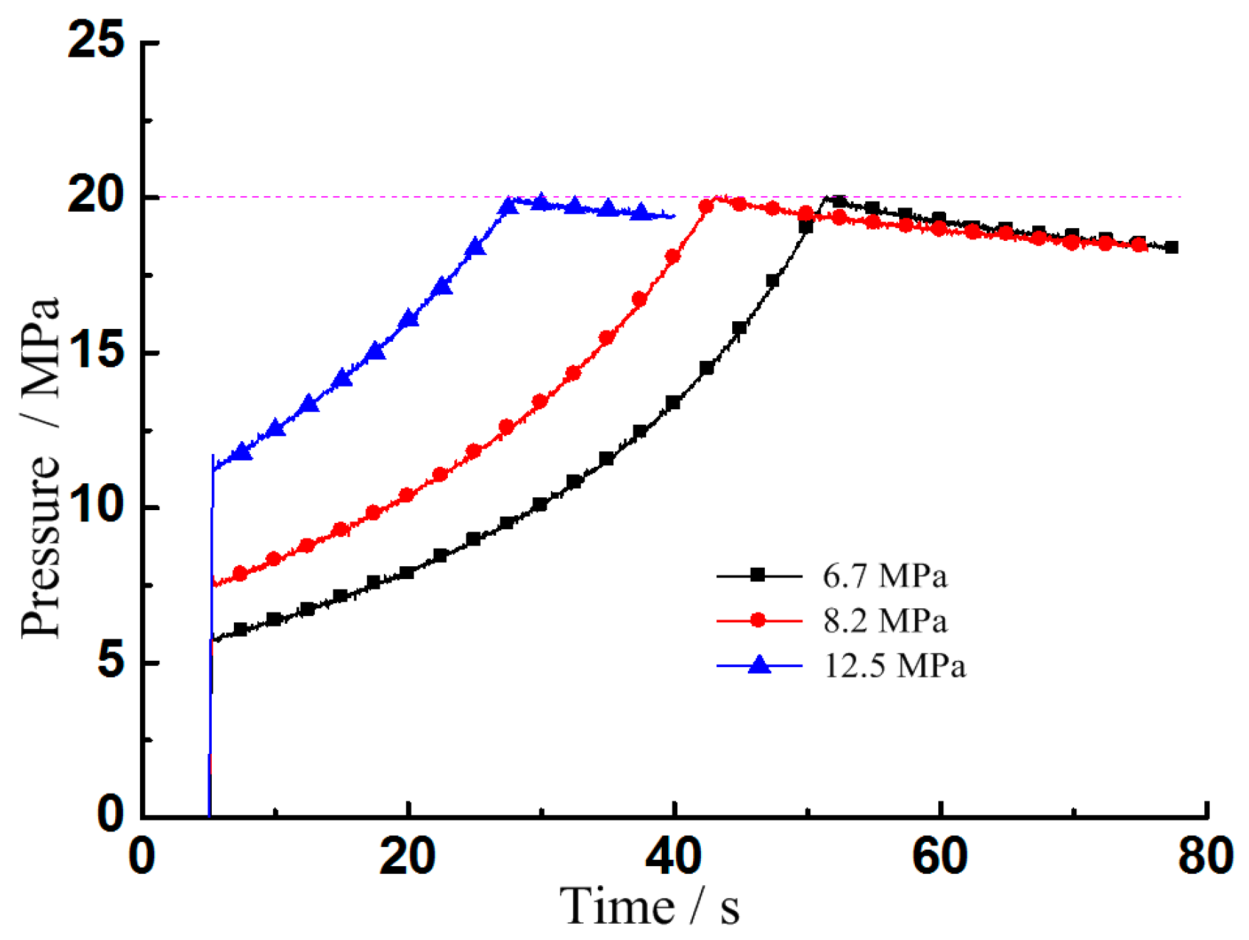
Figure 11 shows the pressure of the HA during the energy regeneration process under different pre-charge pressures. When the valve 14 is working at the bottom position at a time of 5 s, the flow rate out of the PRV flows into the HA through the valve 14, which leads to an increase in the pressure in the HA. When the pressure in HA reaches the pre-set pressure of 20 MPa, the valve 14 works at the top position and allows flow from the PRV into the tank. The HA stops regenerating energy and there is a little decrease of the pressure when the valve 14 is powered off. This is because the connecting line between the PRV and the HA is very long in addition to the hydraulic fluid leakage occurring in check valve 15 and safety shut-off valve 16 in the test rig. The trend of the HA pressure in Figure 11 matches that in Figure 8. This indicates that the simulation model and the test rig match well, with well-chosen simulation parameters.
When the pre-charge pressure of HA is 6.7 MPa and the regulation pressure of the PRV is 21.5 MPa, the PRV is powered on at the time of 5 s and the valve 14 is powered on at the time of 7.4 s to charge the HA. It can be seen from Figure 12 that, before the valve 14 is powered on, both the pressure of the inlet pressure and the pressure in the spring chamber are kept at a constant level. When the HERU is connected to the outlet of the PRV, both the pressures decrease due to a decrease in the fluid force on the main spool until the pressure in HA is almost equal to the pressure in the spring chamber. Following this, the three pressures increase until the pressure in HA reaches the set value and the valve switches to the top position. There is a pressure fluctuation when the valve 14 is switched from the bottom position to the top position. During this process, the port of the valve 14 and the outlet of the PRV first closes. After this, the oil flowing into the PRV has no channel to flow into and holds up in the inlet, which increase the pressure of the inlet and the pressure in the spring chamber in addition to the enlargement of the orifice of the main valve. After valve 14 begins to work at the top position, the outlet of the PRV is connected to the tank. Due to the larger orifice, the pressure in the inlet and the spring chamber decrease, which leads to the smaller orifice and an increase in the pressure. After a short period of regulation, both the inlet pressure and the pressure in the spring chamber return to their initial values.
Figure 12 illustrates that independent of whether HERU is connected or disconnected to the outlet of the PRV, the inlet pressure of the PRV can be still maintained around the set pressure of 21.5 MPa.
Figure 13 shows the flow rate out of the PRV through the outlet. It can be seen that independent of whether the outlet of the PRV is connected to the HERU, the flow rate out of the PRV is almost the same after the self-regulation.
Figure 14 shows the inlet pressure of the PRV under the different maximum pressures of HA. It can be seen that when the PRV is powered on at the time of 1 s, the inlet pressure of the PRV is almost the same as the regulating pressure, which is 21.5 MPa. The inlet pressure slightly decreases with an increase in the maximum pressure of HA, with the maximum error of 0.5 MPa being nearly 2.3% compared to the regulating pressure.
5.2.2. Regeneration Efficiency
One objective of the experiment is to determine how much energy can be stored by the HERU. As seen in Figure 12, the area between the pressure of the HA and inlet pressure of the PRV is the energy loss through the PRV. When combined with Figure 11, a higher pre-charge pressure results in a smaller area denoting the energy loss.
The energy loss through PRV without HERU is given by
where Er is the energy loss through PRV without HERU.
The regenerated energy in HA can be obtained as
where p0, p1, and p2 are the pre-charge pressure, minimum pressure, and maximum pressure of the HA, respectively; and V0 is the volume of the HA. The charging process is short and the compression of the gas can be considered as the adiabatic process. The gas index of the ideal gas n equals to 1.4.
The regeneration efficiency of the HERU is calculated as:
The energy loss and the regenerated energy by HA are listed in Table 1 when the pre-charge pressure is 6.7, 8.2 and 12.5 MPa, respectively. The target pressure of the HA is set to 20 MPa for the three conditions. It can be seen from Table 1 and Figure 10 that when the pre-charge pressure is 6.7 MPa, there is maximum energy loss through PRV without HERU and maximum regenerated energy in HERU. However, the lowest regeneration efficiency happens at this time, being only 61.2%. With an increase in the pre-charge pressure, the energy loss through PRV without HERU and the regenerated energy in HERU decrease, but there is an increase in regeneration efficiency. The reason is that the volume of the HA is the same in the test rig. When the pre-charge pressure of the HA is high, the time for regenerating the energy loss of the PRV via the HA is short, which is seen in Figure 10. As the inlet pressure and the flow rate of PRV are nearly the same, a higher pre-charge pressure results in less energy loss through PRV without HERU. Furthermore, when the pre-charge pressure is high, the outlet pressure of PRV is high. Following this, the pressure drop between the inlet and outlet reduces, which means that the regeneration efficiency will increase. The volume of the HA is chosen according to the installation space. In general, a larger volume means more energy that can be stored.
The choice of pre-charge pressure depends on the requirements. If the regeneration efficiency is the main consideration, a higher pre-charge pressure should be chosen. However, if there is need to regenerate as much energy as possible, a smaller pre-charge pressure should be chosen or multiple HA should be utilized.
6. Conclusions
The proposed configuration of the PRV with the HERU connected to its outlet was discussed through the simulation and experimental analysis. These useful conclusions are obtained:
- (1)
- To reduce the energy loss of the relief valve, the HERU is connected to the outlet of the PRV, which can increase the outlet pressure and thus reduce the pressure drop between the inlet and outlet. The overflow energy loss that backs into the tank directly in the traditional working conditions is converted into hydraulic energy, which is stored in the hydraulic accumulator and can be released when needed.
- (2)
- The PRV with HERU connected to the outlet can still have a better function in regulating pressure. The flow rate of the PRV is almost constant independent of whether the HERU is connected or disconnected to the PRV after a short adjusting time.
- (3)
- A higher pre-charge pressure can achieve higher regeneration efficiency, while the lower pre-charge pressure can regenerate more energy. The chosen pressure of the HA should consider the regeneration efficiency, the actual working style, and the installation space.
- (4)
- Further research will concentrate on the multiple HA used in the proposed HERU and the control of them to regenerate as much energy as possible with a higher regeneration efficiency.
Acknowledgments
The authors gratefully acknowledge the financial support of National Natural Science Foundation of China (Grant No. 51505160), Promotion Program for Young and Middle-aged Teachers in Science and Technology Research of Huaqiao University (ZQN-YX201), Industry Cooperation of Major Science and Technology Project of Fujian Province (2017H6101), Open Foundation of the State Key Laboratory of Fluid Power and Mechatronic Systems (GZKF-201517 & GZKF-201611), and Natural Science Foundation of Fujian Province (2017J01087).
Author Contributions
Tianliang Lin proposed the idea of using the energy regeneration unit to recovery the energy loss through the relief valve. Qiang Chen. and Haoling Ren designed the experiments. Qiang Chen, Yi Zhao and Cheng Miao performed the experiments and analyzed the data. Shengjie Fu and Qihuai Chen contributed to the control of the test rig. Tianliang Lin and Haoling Ren wrote the paper.
Conflicts of Interest
The authors declare no conflict of interest.
Nomenclatures and Symbols
p1 is the inlet pressure of the PRV; p2 is the outlet pressure of the PRV; Δp is the pressure drop between the inlet and outlet; p3 is the pressure of the spring chamber; pa0 is the pre-charge pressure of HA; ps is the outlet pressure of the pump; pa is the pressure of the HA; F0 is the pre-tightening force of the reset spring; A1 is the effective cross-sectional area of the main spool; Va0 is the rated volume of HA; Va1 and pa1 are the gas volume and pressure when the HA is at the minimum working pressure; Va2 and pa2 are the gas volume and pressure when the HA is at the maximum working pressure; ΔVa1 is the maximum oil volume that is stored in HA when the pressure in HA increases from pa1 to pa2; n is the polytrophic exponent; C is a constant; is the energy density of the HA; Er is the energy loss through PRV without HERU; Ea is the regenerated energy in HA; Q is the flow rate of the PRV; ηr is the regeneration efficiency of the HERU.
References
- Shen, W.; Jiang, J.; Su, X.; Karimi, H.R. Control strategy analysis of the hydraulic hybrid excavator. J. Frankl. Inst. 2015, 352, 541–561. [Google Scholar] [CrossRef]
- Chen, Q.; Wang, Q.; Wang, T. A novel hybrid control strategy for potential energy regeneration systems of hybrid hydraulic excavators. Proc. Inst. Mech. Eng. Part I J. Syst. Control Eng. 2016, 230, 375–384. [Google Scholar] [CrossRef]
- Lin, T.; Wang, Q.; Hu, B.; Gong, W. Development of hybrid powered hydraulic construction machinery. Autom. Constr. 2010, 19, 11–19. [Google Scholar] [CrossRef]
- Shen, G.; Zhu, Z.C.; Li, X.; Tang, Y.; Hou, D.; Teng, W. Real-time electro-hydraulic hybrid system for structural testing subjected to vibration and force loading. Mechatronics 2016, 33, 49–70. [Google Scholar] [CrossRef]
- Shi, Y.; Li, F.; Cai, M.; Yu, Q. Literature review: Present state and future trends of air-powered vehicles. J. Renew. Sustain. Energy 2016, 8, 325–342. [Google Scholar] [CrossRef]
- Chen, Q.; Wu, W.; Liu, W.; Zhang, X. Research on pump control signal of excavator positive control system. J. Hefei Univ. Technol. (Nat. Sci.) 2014, 37, 645–649. [Google Scholar]
- Cheng, M.; Zhang, J.; Ding, R.; Xu, B. Pump-based compensation for dynamic improvement of the electrohydraulic flow matching system. IEEE Trans. Ind. Electron. 2016, 64, 2903–2913. [Google Scholar] [CrossRef]
- Sugimura, K.; Murrenhoff, H. Hybrid Load Sensing–Displacement Controlled Archtecture for Excavators. In Proceedings of the 14th Scandinavian International Conference on Fluid Power (SICFP’15), Tampere, Finland, 20–22 May 2015. [Google Scholar]
- Xu, B.; Liu, Y.J.; Yang, H.Y. Research on electro-hydraulic proportional load sense separate meter in and separate meter out control system. Hunan Daxue Xuebao/J. Hunan Univ. Natl. Sci. 2010, 37, 190–196. [Google Scholar]
- Quan, Z.; Quan, L.; Zhang, J. Review of energy efficient direct pump controlled cylinder electro-hydraulic technology. Renew. Sustain. Energy Rev. 2014, 35, 336–346. [Google Scholar] [CrossRef]
- Shen, W.; Jiang, J. Analysis and development of the hydraulic secondary regulation system based on the CPR. In Proceedings of the International Conference on Fluid Power and Mechatronics, Beijing, China, 17–20 August 2011; pp. 117–122. [Google Scholar]
- Hippalgaonkar, R.; Ivantysynova, M.; Zimmerman, J. Fuel savings of a mini-excavator through a hydraulic hybrid displacement controlled system. In Proceedings of the 8th International Fluid Power Conference, Dresden, Germany, 26–28 March 2012; pp. 139–153. [Google Scholar]
- Ren, H.; Lin, T.; Huang, W.; Fu, S.; Chen, Q. Characteristics of the energy regeneration and reutilization system during the acceleration stage of the swing process of a hydraulic excavator. Proc. Inst. Mech. Eng. Part D J. Automob. Eng. 2017, 231, 842–856. [Google Scholar] [CrossRef]
- Wang, B. High Speed On-Off Valve Self-adapting Clamping System. J. Appl. Sci. 2014, 14, 279–284. [Google Scholar] [CrossRef]
- Shi, Y.; Wu, T.; Cai, M.; Wang, Y.; Xu, W. Energy conversion characteristics of a hydropneumatic transformer in a sustainable-energy vehicle. Appl. Energy 2016, 171, 77–85. [Google Scholar] [CrossRef]
- Wang, T.; Wang, Q. Design and analysis of compound potential energy regeneration system for hybrid hydraulic excavator. Proc. Inst. Mech. Eng. Part I J. Syst. Control Eng. 2012, 226, 1323–1334. [Google Scholar] [CrossRef]
- Wang, T.; Wang, Q.; Lin, T. Improvement of boom control performance for hybrid hydraulic excavator with potential energy recovery. Autom. Constr. 2013, 30, 161–169. [Google Scholar] [CrossRef]
- Lin, T.; Chen, Q.; Ren, H.; Miao, C.; Chen, Q.; Fu, S. Influence of the energy regeneration unit on pressure characteristics for a proportional relief valve. Proc. Inst. Mech. Eng. Part I J. Syst. Control Eng. 2017, 231, 189–198. [Google Scholar] [CrossRef]
Figure 1.
Comparison of the pilot relief valve (PRV) with and without hydraulic energy regeneration unit (HERU).
Figure 1.
Comparison of the pilot relief valve (PRV) with and without hydraulic energy regeneration unit (HERU).

Figure 2.
Working principles of the PRV (1—Main valve spool; 2—Orifice; 3—Reset spring; 4—Pilot valve; 5—HERU; 6—Spring chamber).
Figure 2.
Working principles of the PRV (1—Main valve spool; 2—Orifice; 3—Reset spring; 4—Pilot valve; 5—HERU; 6—Spring chamber).

Figure 3.
Principle diagram of the test for the PRV with HERU (1—2/2 Solenoid directional valve; 2—Safety valve; 3—Filter; 4—Fixed displacement pump; 5—Electric variable frequency motor; 6 and 15—Check valve; 7 and 18—Pressure gauge; 8, 12, and 13—Flow meter; 9—PRV; 10, 11, 19, and 20—Pressure sensor; 14—3/4 Solenoid directional valve; 16—Safety shutoff valve; 17—HA (HERU)).

Figure 4.
Control flow of the HERU.

Figure 5.
Simulation model in AMESim.

Figure 6.
Pressures during the energy regeneration process.

Figure 7.
Flow rate and displacement of main valve of the PRV during the energy regeneration process.
Figure 7.
Flow rate and displacement of main valve of the PRV during the energy regeneration process.
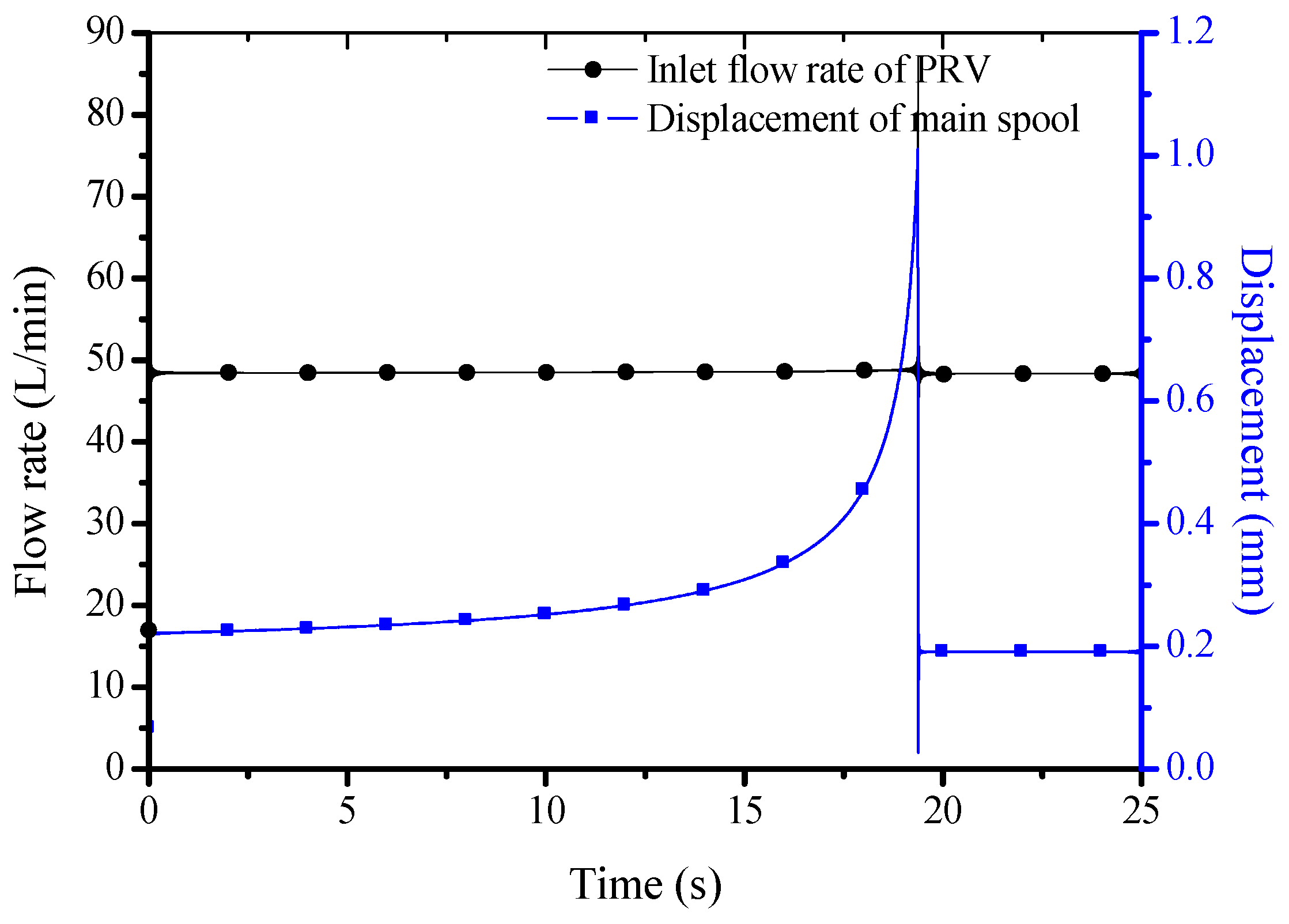
Figure 8.
Compression of hydraulic accumulator (HA) pressure with different pre-charge pressures.

Figure 9.
Influence of the outlet pressure of the PRV on the characteristics of the PRV.

Figure 10.
Layout of the tested unit.

Figure 11.
HA pressure with different pre-charge pressures during the energy regeneration process.

Figure 12.
Pressures during the energy regeneration process.

Figure 13.
Flow rate out of the PRV.

Figure 14.
Experimental results with different maximum pressures of HA. (a) Inlet pressure of PRV; (b) Inlet pressure vs. maximum pressure of HA.
Figure 14.
Experimental results with different maximum pressures of HA. (a) Inlet pressure of PRV; (b) Inlet pressure vs. maximum pressure of HA.


Table 1.
Energy regenerated with different pre-charge pressures.
| Pre-charge pressure/MPa | 6.7 | 8.2 | 12.5 |
| Energy loss through PRV without HERU/kJ | 206.3 | 166.0 | 94.8 |
| Regenerated energy in HA/kJ | 126.3 | 114.8 | 79.2 |
| Regeneration efficiency/% | 61.2 | 69.2 | 83.6 |
© 2017 by the authors. Licensee MDPI, Basel, Switzerland. This article is an open access article distributed under the terms and conditions of the Creative Commons Attribution (CC BY) license (http://creativecommons.org/licenses/by/4.0/).
Share and Cite
MDPI and ACS Style
Lin, T.; Chen, Q.; Ren, H.; Zhao, Y.; Miao, C.; Fu, S.; Chen, Q. Energy Regeneration Hydraulic System via a Relief Valve with Energy Regeneration Unit. Appl. Sci. 2017, 7, 613. https://doi.org/10.3390/app7060613
AMA Style
Lin T, Chen Q, Ren H, Zhao Y, Miao C, Fu S, Chen Q. Energy Regeneration Hydraulic System via a Relief Valve with Energy Regeneration Unit. Applied Sciences. 2017; 7(6):613. https://doi.org/10.3390/app7060613
Chicago/Turabian StyleLin, Tianliang, Qiang Chen, Haoling Ren, Yi Zhao, Cheng Miao, Shengjie Fu, and Qihuai Chen. 2017. "Energy Regeneration Hydraulic System via a Relief Valve with Energy Regeneration Unit" Applied Sciences 7, no. 6: 613. https://doi.org/10.3390/app7060613
Note that from the first issue of 2016, this journal uses article numbers instead of page numbers. See further details here.