Experimental Study of Vibration Isolation Characteristics of a Geometric Anti-Spring Isolator

1
Department of Precision Machinery and Precision Instrumentation, University of Science and Technology of China, No. 443, Huangshan Road, Shushan District, Hefei 230026, China
2
CAS Key Laboratory of Mechanical Behavior and Design of Materials, Department of Modern Mechanics, University of Science and Technology of China, No. 443, Huangshan Road, Shushan District, Hefei 230026, China
*
Author to whom correspondence should be addressed.
Appl. Sci. 2017, 7(7), 711; https://doi.org/10.3390/app7070711
Submission received: 12 June 2017
/
Revised: 28 June 2017
/
Accepted: 6 July 2017
/
Published: 10 July 2017
(This article belongs to the Section Mechanical Engineering)
Abstract
:In order to realize low-frequency vibration isolation, a novel geometric anti-spring isolator consisting of several cantilever blade springs are developed in this paper. The optimal design parameters of the geometric anti-spring isolator for different nonlinear geometric parameters are theoretically obtained. The transmissibility characteristic of the geometric anti-spring isolator is investigated through mathematical simulation. A geometric anti-spring isolator with a nonlinear geometric parameter of 0.92 is designed and its vibration isolation performance and nonlinearity characteristic is experimentally studied. The experiment results show that the designed isolator has good low-frequency vibration isolation performance, of which the initial isolation frequency is less than 3.6 Hz when the load weight is 21 kg. The jump phenomena of the response of the isolator under linear frequency sweep excitation are observed, and this result demonstrates that the geometric anti-spring isolator has a complex nonlinearity characteristics with the increment of excitation amplitude. This research work provides a theoretical and experimental basis for the application of the nonlinear geometric anti-spring low-frequency passive vibration isolation technology in engineering practice.
1. Introduction
For a linear passive vibration isolation system, the vibration isolation performance is effective only when the frequency of external disturbance is more than times the natural frequency. In order to attenuate vibration in the low-frequency band, one must reduce the stiffness of the linear vibration isolation system. However, reduction of the stiffness will diminish load bearing capacity of linear vertical vibration isolation system, resulting in undesirable excess deflection and over-stress of spring material. Finally, the linear vibration isolation system will fail to work well. In order to settle this problem, nonlinear vibration isolation systems attract great interests, because they exhibit the typical characteristics of high static stiffness and low dynamic stiffness (HSLDS), which are very different from the invariant stiffness characteristic of linear vibration isolation system [1]. At the static equilibrium point, nonlinear vibration isolation systems can not only provide sufficiently large static stiffness to reduce static deflection, but also offer very small dynamic stiffness to obtain good low-frequency vibration isolation performance.
So far, nonlinear vibration isolation systems are mainly realized by integrating negative stiffness structures with linear positive stiffness springs. There are several methods to achieve negative stiffness characteristics. Inclined spring negative stiffness structure is the most studied one in the literature. Carrella et al. [2,3,4] firstly reported a quasi-zero-stiffness system in which two inclined springs connected in parallel with one vertical spring. Typically, this system outperforms the linear system provided that the system parameters are chosen appropriately. Based on this work, Ahn [5] put forward design guidelines for the quasi-zero-stiffness isolator and solved the performance limit of this isolator. To further improve vibration isolation effectiveness of the vehicle seat, the quasi-zero-stiffness vibration isolation model was developed [6,7], and it is experimentally confirmed that the proposed system offers a larger isolation frequency range and a higher attenuation rate than that of the linear system. After that, various methods were conducted to develop the quasi-zero-stiffness vibration isolator, and the effects of various loads and archetypal dynamical model of this quasi-zero stiffness isolator were discussed in the literature [8,9]. Moreover, a quasi-zero stiffness isolator using Euler buckled beams as negative stiffness corrector was reported and the results showed that introducing the negative stiffness was an effective way to lower the resonance frequency even with the stiffness and load imperfections [10,11]. Although quasi-zero stiffness vibration isolation systems (QZS-VIS) are potentially advantageous in many practical applications, QZS-VIS have many disadvantages, such as the easiness to lose stability, low loading capability and potential bifurcation effect at equilibrium [3,5,11,12].
Utilizing permanent magnets and electromagnets to produce negative stiffness is another method for the negative stiffness characteristics [13,14,15,16]. Xu et al. [17] presented the geometric nonlinear magnetic vibration isolation devices with the quasi-zero-stiffness characteristic. In comparison to the corresponding linear system, the vibration isolation range of the proposed system can be largely extended to the lower frequency domain. Zheng et al. [18] employed a pair of coaxial ring permanent magnets installed in parallel with the mechanical spring to reduce the resonance frequency of the linear isolator, and the proposed quasi-zero-stiffness isolator can really outperform a linear isolator. Zhu et al. [19] designed a novel six degrees of freedom vibration isolator system utilizing magnetic levitation, which realized inherent quasi-zero stiffness in the vertical direction, and zero stiffness in other five degrees of freedoms. The negative stiffness structures that originated from the permanent magnets and electromagnets were very effective. However, they were quite thermally sensitive and may induce unwanted couplings to external electromagnetic fields.
In addition, there are many other novel designs for quasi-zero-stiffness vibration isolation systems reported, such as sliding beam structure [20], composite bi-stable plate [21], scissor-like structured platform [22], and super elastic shape memory alloy bars [23]. However, because of structural complexity or unknown structural stability or environmental dependence, much deep-in research work still needs to be done, with the objective of further industrial application.
The geometrical anti-spring structure was first proposed by Bertolini [24] and Cella [25] for the purpose of seismic attenuation. It was successfully applied in optical table prototype designed for advanced LIGO (Laser Interferometer Gravitational wave Observatory) [26] and external injection bench of the Advanced Virgo gravitational wave detector [27,28]. Due to its nonlinear characteristics of high static low dynamic stiffness, the geometric anti-spring structure would be a perfect candidate for the design of low-frequency vibration isolation system. In contrast to other designs for the nonlinear isolator, the advantages of geometric anti-spring isolator include structuralicity simple and compactness, space saving and insensitive to temperatures or external electromagnetic fields, and so on. However, expect for the seismic attenuation in gravitational wave observatory, the geometric anti-spring isolator has not been applied in any other vibration reduction application. And the detailed nonlinear stiffness characteristic of the geometric anti-spring structure have not been intensively investigated. The effect of load and stiffness imperfection on the performance of this nonlinear isolation structure has not been discussed, which is very important for its further application in the field of vehicles, ships, and other precision equipment, especially for the situation under the excitation of low frequency (several Hz) and large amplitude.
In this study, aiming at settling the pressing issue for isolating the disturbance of several Hz in precision instruments in vehicles and ships, a novel geometric anti-spring isolator for the low-frequency vibration isolation is developed and its vibration isolation performance and nonlinearity characteristic are investigated mathematically and experimentally. In Section 2, the genetic algorithm was used to achieve the numerical solution to the differential boundary value problem that describes the mechanical properties of the blade spring. The stiffness nonlinearity is investigated and the dimensionless optimal design parameters of the geometric anti-spring vibration isolation structure for different nonlinear geometric parameters are obtained. Mathematical simulation based on four order Runge-Kutta algorithm is carried out to investigate the transmissibility characteristic of the geometric anti-spring isolator in Section 3. The influence of geometric parameter, excitation amplitude, load weight and viscous damping on the transmissibility of the geometric anti-spring isolator are investigated theoretically. Then, a geometric anti-spring isolator with a nonlinear geometric parameter of 0.92 is fabricated and experimentally studied. The experiment setup and results are presented in Section 4. Conclusions are drawn in Section 5. This work will enhance the understanding of vibration attenuation mechanism of geometric anti-spring structure and provide further design guidelines for the broader application of the geometric anti-spring isolator.
2. Geometric Anti-Spring Structure
The geometric anti-spring isolator (Figure 1a) consists of several quasi-trapezoid cantilever blade springs. The bottoms of blade springs are fixed to a massive base with V-type fixtures and their vertices are connected to each other through a central load plate. Both the bottoms and the vertices of the blade spring are kept at a constant angle to the horizontal direction. The central load plate connected with the mass load is limited to move along the vertical direction. The shape of cantilever blade spring is shown in Figure 1d. The effective length of spring is , and the width of the blade spring is represented by , with . The shape function of the blade spring is
where , , and . This particular shape is chosen to achieve a uniform inner stress distribution [25]. Meanwhile, total stress of the spring will be the smallest in comparison to that with other shapes when the vibration isolation structure works at the low stiffness area. The blade spring has a constant thickness, which is much smaller than both the length and the width of the spring.
According to the geometric symmetry, the mechanical property of the geometric anti-spring structure can be obtained through mechanical analysis of single blade spring. Figure 1e shows a one dimension mechanical model of the blade spring, in which the influence of thickness is ignored. Rectangular coordinate system O-(X,Y), of which the origin O is sited at the bottom of the blade spring, X axis represents the horizontal direction and Y axis is for the vertical direction, is established to analyze the mechanical property of the blade spring. The variable is the curvilinear coordinate along the length direction of the blade spring. It is convenient to define as the angle between the tangent of curvilinear and the positive direction of X axis of the rectangular coordinate system. The quantity represents horizontal constraint force and the quantity represents vertical payload applied on the vertex of the blade spring. The relationship between the dimensionless force and actual force is shown as follows.
Here, is Young’s modulus of the material of blade spring. Dimensionless vertical coordinate and dimensionless horizontal coordinate of blade spring’s vertex are given by
Here, is dimensionless arc length.
According to the literature [25], the mechanical properties of the blade spring can be described by the first order differential boundary equations as follows:
Here, is an intermediate parameter. Boundary conditions are , .
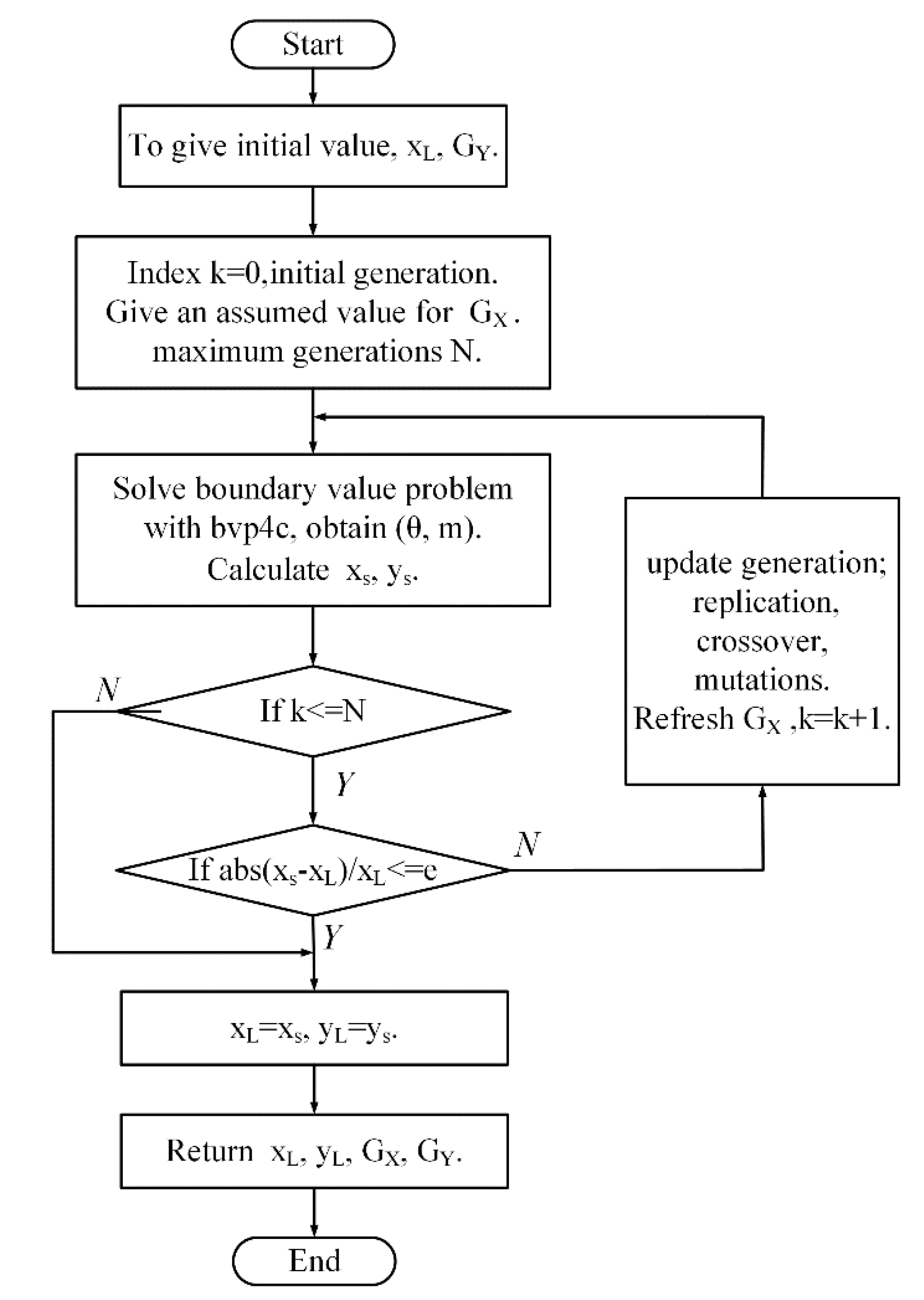
In general, the exact analytical solution of Equation (4) cannot be obtained theoretically with an explicit expression formulation. The dimensionless horizontal coordinate of spring’s vertex is the key parameter to distinguish the mechanical characteristic of the geometric anti-spring isolator under different work state. For the sake of simplicity, the dimensionless horizontal coordinate of the vertex of the spring is referred to the nonlinear geometric parameter in this paper. Utilizing a MATLAB program based on genetic algorithm, the approximately numerical solution of Equation (4) was obtained. The flow chart of the algorithm to solve the boundary problem of Equation (4) is shown in Figure 2. This solution algorithm transforms the differential boundary problem to an optimization problem. The horizontal constraint force is unknown in Equation (4). The objective of the optimization algorithm is to gain the horizontal constraint force of the blade spring under certain a vertical load and a nonlinear geometric parameter. The procedure of the solution algorithm is given as follow.
Step 1: Giving an initial assuming value of horizontal constraint force for the given vertical load and nonlinear geometric parameter .
Step 2: Solve the boundary problem mathematically and get the horizontal coordinate of the vertex of the spring.
Step 3: Calculate the relative error between and . If the calculated error is less than the required accuracy e (=1 × 10⁻⁹), record the horizontal force and go to Step 5. Otherwise, go to Step 4.
Step 4: Update the assuming value of the horizontal constraints force using the genetic algorithm function ga() given by Matlab software (Matlab 2012a) and repeat Step 2 and Step 3.
Step 5: Solve the boundary problem mathematically under the given vertical force and the recorded optimal horizontal force . And get the vertical coordinate of the vertex of the spring.
In this optimization problem, the number of variables for the genetic algorithm function ga() is 1. Some key arguments in the options of the genetic algorithm function ga() are listed in Table 1. The other arguments are the defaults.
In the solution procedure, when the geometric parameter is larger than 0.9027, optimization terminates when the average change in the fitness value is less than the options.TolFun. The maximum iteration generation is less than 100. The optimization algorithm is time-saving. There is no multi-value solution obtained, which means that the vertical force and the vertical coordinate of the blade spring’s vertex are one to one correspondence and no negative stiffness appears. According to the literature [25], the negative stiffness appears when the nonlinear geometric parameter is smaller than 0.9027. And for the situation that the geometric parameter is less than 0.9027, the time of optimization progress is long when the nondimensional vertical force is close to −1.75 and the multi-value solution can not be achieved. Therefore, the negative stiffness characteristics of the geometric anti-spring isolator when the nonlinear geometric parameter is smaller than 0.9027 are not discussed in this paper. This will be studied in the future work.
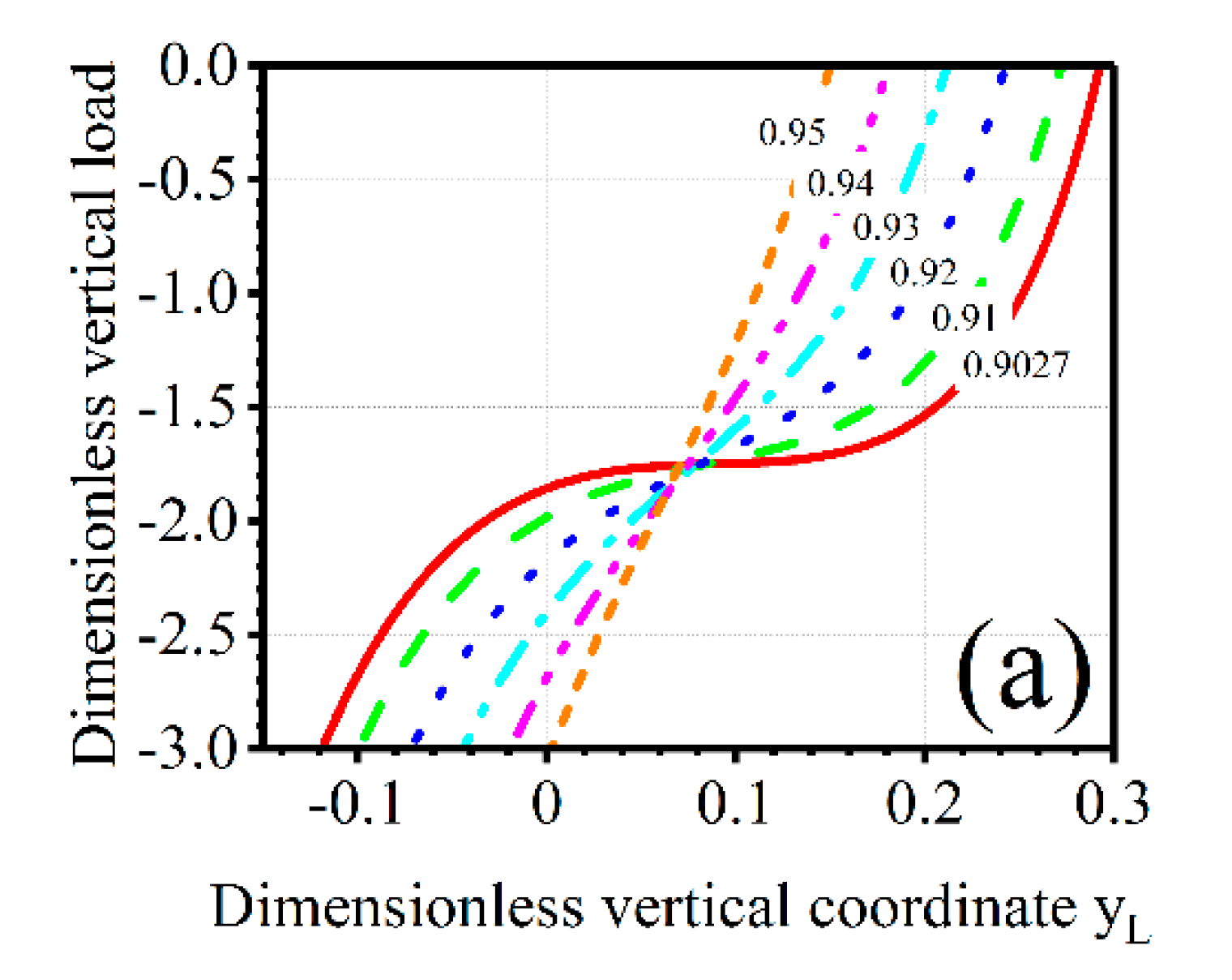
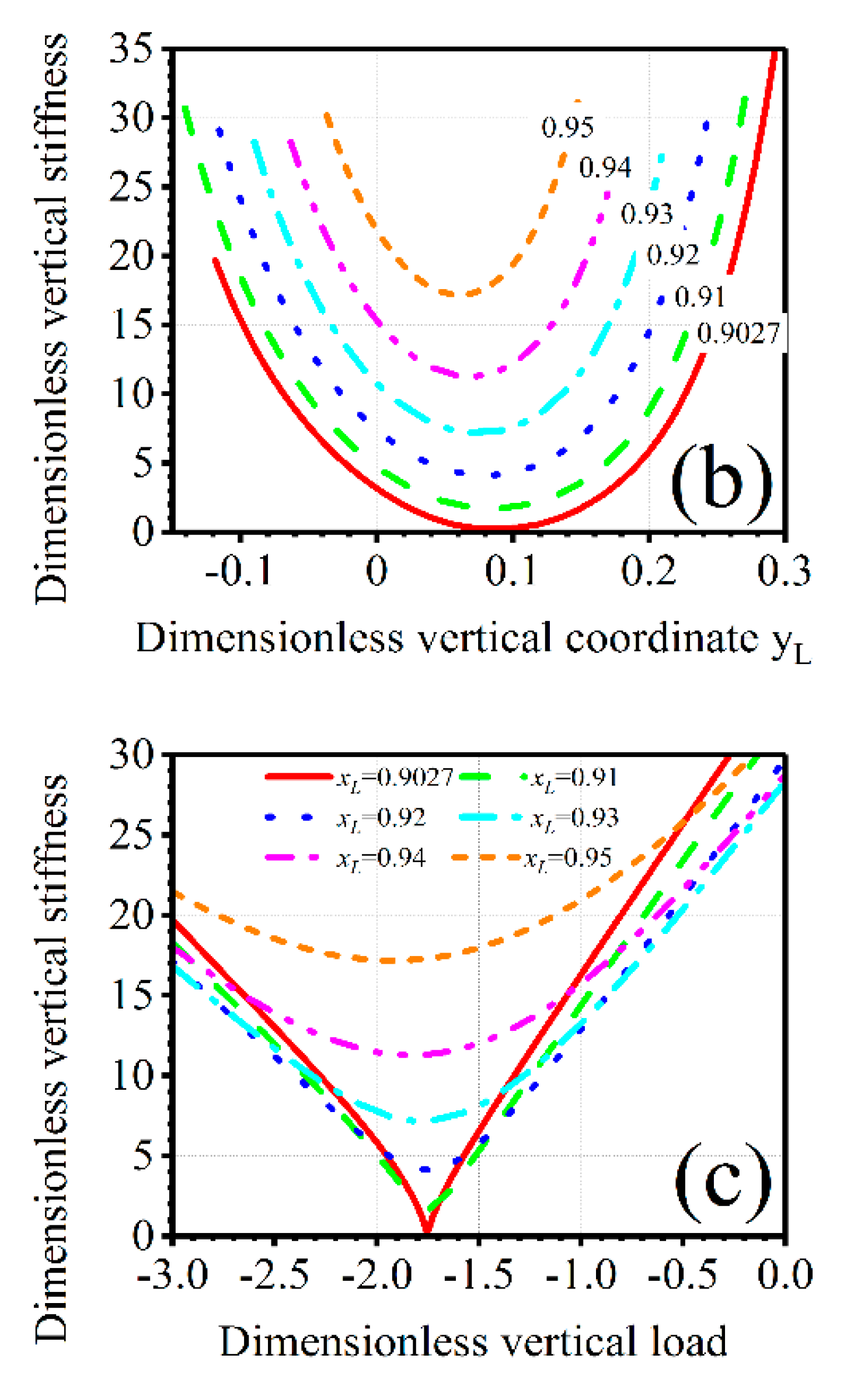
Figure 3a depicts the relationship between dimensionless vertical force and dimensionless vertical coordinate of spring’s vertex. As the nonlinear geometric parameter decreases, the curve of dimensionless vertical force vs. dimensionless vertical coordinate changes from an approximately straight line to a nonlinear curve. When the dimensionless vertical coordinate approaches to 0.1, dimensionless vertical force grows slowly, which means that the geometric anti-spring isolator possesses very low local stiffness in these load range.
Taking a first order derivative to with respect to , dimensionless dynamic stiffness is obtained (Figure 3b,c). With the decreasing of the nonlinear geometric parameter , the nonlinearity of the geometric anti-spring isolator is largely enhanced and the dimensionless lowest dynamic stiffness decreases. When , the minimum stiffness approaches zero. In order to achieve better vibration isolation performance, it is essential to settle the static equilibrium point of the isolator at the minimum stiffness point, which is called the optimal or rated working point. As the nonlinear geometric parameter decreases, the range of displacement for low stiffness is enlarged but the range of the load goes to be narrow. When the nonlinear geometric parameter is small, the change of the load will largely increase the dynamic stiffness of the isolator in low stiffness area.
According to the vibration theory, the natural angular frequency of the geometric anti-spring structure can be calculated as follows,
And the dimensionless angular frequency is given by:
The dimensionless minimum dynamic stiffness and corresponding dimensionless natural angular frequency for different dimensionless horizontal coordinates are shown in Table 2. The corresponding dimensionless vertical coordinate and vertical force at the rated working point are given at the same time.
As the nonlinear geometric parameter decreases, dimensionless minimum dynamic stiffness and natural angular frequency decrease. The dimensionless vertical coordinate increases with the decrement of the nonlinear geometric parameter but vertical force slightly decreases. The carrying capacity of the geometric anti-spring structure reduces with the reduction of the nonlinear geometric parameter.
According to the mathematically theoretical analysis results, the relationship between dimensionless restoring force and displacement of the geometric anti-spring isolator for different nonlinear geometric parameters can be accurately fitted with a seven order polynomial function:
Here, is the dimensionless vertical displacement of the geometric anti-spring isolator and are the fitting coefficients, which are shown in Table 3.
Figure 4a shows the dimensionless vertical force of the geometric anti-spring isolator for different nonlinear geometric parameters, where the gray solid line represents the mathematical calculated results based on the genetic algorithm and different types of color lines represent the polynomial fitting results. It can be seen that the curve of force vs. displacement of the geometric anti-spring isolator in low-frequency area goes much flatter with the decrement of the geometric parameter. The low dynamic stiffness characteristic is also apparent. However, the static displacement of the geometric anti-spring isolator in the low stiffness area increases as the nonlinear geometric parameter decreases, which means that the static stiffness of the isolator will reduce with the decrement of the nonlinear geometric parameter.
Figure 4b shows the dimensionless dynamic stiffness characteristic at the rated working point. As the nonlinear geometric parameter decreases, both the static stiffness and dynamic tangent stiffness of the geometric anti-spring isolator decrease. However, the dynamic stiffness is always less than the static stiffness at the rated working point. The ratio of dynamic stiffness to static stiffness at the rated working load decreases with the decrement of the nonlinear geometric parameter. When the nonlinear geometric parameter is 0.9027, the ratio of dynamic stiffness to static stiffness tend to zero. Therefore, the geometric anti-spring isolator possesses a good high static low dynamic stiffness characteristic. When the nonlinear geometric parameter tends to be 0.9027, the quasi-zero stiffness can even be realized.
3. Mathematical Simulation
In order to theoretically analyze the vibration isolation performance of the geometric anti-spring isolator, a mathematical simulation based on a four order Runge-Kutta algorithm is carried out. When subjected to base excitation , the governing equation of motion in the geometric anti-spring isolator is
where represents the relative motion between the excitation displacement of base and the displacement of mass. is the load weight. is the static displacement. The relationship between the load weight and the static displacement is given by .
Introducing the dimensionless parameters
Equation (8) can be written as
where and denote the second and first derivative of the dimensionless relative displacement with respect to the dimensionless time . The intermediate variable is the angular frequency of the equivalent linear isolator. For the equivalent linear vibration isolation system, the dimensionless initial isolation frequency is .
Figure 5 shows the Matlab/Simulink program (Matlab 2012a) used for solving the nonlinear dynamic differential equation (Equation (9)) of motion of the geometric anti-spring isolator. The model of nonlinear restoring force (Figure 5b) is set up based on Equation (7). Giving the initial state conditions (initial displacement and initial velocity), time domain solution of Equation (9) can be obtained using four order Runge-Kutta algorithm. Calculating the ratio of the absolute acceleration amplitude of the load mass to the excitation acceleration amplitude , the acceleration transmissibility of the geometric anti-spring isolator can be obtained. Here, the effects of the nonlinear geometric parameter, excitation displacement amplitude, static payload weight and viscous damping ratio on the transmissibility of the geometric anti-spring isolator are considered.
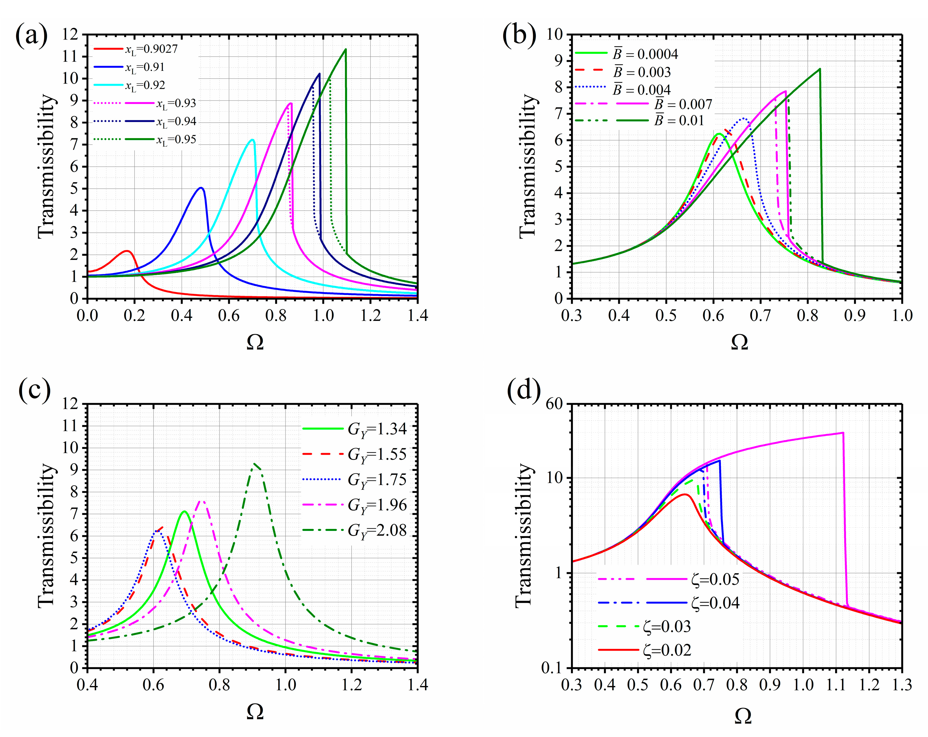
The transmissibility curves of the geometric anti-spring isolator are shown in Figure 6. Due to the existence of the nonlinearity, the response of the geometric anti-spring isolator under certain excitation levels is dependent on the initial condition. The transmissibility curves of the geometric anti-spring isolator for the situation of gradually increasing frequency and decreasing frequency are different when the nonlinearity is strong, which are distinguished by different types of lines.
From Figure 6a, it can be seen that as the nonlinear geometric parameter grows, the resonance frequency of the geometric anti-spring isolator increases and the nonlinearity enhances as well. When is larger than 0.93, the transmissibility curves in the resonance area do not follow the same path. When the excitation frequency is gradually accumulated, a downward jumping phenomena is observed (as is shown by the solid line). When the excitation frequency is gradually reduced, an upward jumping phenomenon is observed (as is shown by the dotted line). The geometric anti-spring isolator shows a hardening-type stiffness characteristic at the rated load.
As the excitation amplitude increases, the peak area of transmissibility curve deflects to the right and the peak of curve increases (Figure 6b). The nonlinearity of the geometric anti-spring isolator enhances with the increment of excitation amplitude. However, the transmissibility of the isolator in the isolation area for different excitation amplitude does not change too much.
When the geometric parameter is 0.92 and the excitation amplitude is 0.01, the transmissibility peak first decreases and then increases with the increment of the load weight (Figure 6c). When the dimensionless load weight is 1.75 (the rated working load), the resonance frequency reaches to the minimum value. The increment of the resonance frequency of the geometric anti-spring isolator is slow when reducing the load but fast when increasing the load.
As shown in Figure 6d, with increasing of the damping, the peak of the transmissibility curve reduces and the nonlinearity is weakened. The attenuation rate of the transmissibility curve in the isolation area does not change when the damping is not too large. So providing appropriate damping will be profitable to weaken the nonlinearity and retain the good vibration isolation performance of the isolator.
The imperfection of load weight will largely change the nonlinearity characteristic of the geometric anti-spring isolator. Figure 7 shows the transmissibility curves of the geometric anti-spring isolator for different load weights when the nonlinear geometric parameter is 0.92. When the load weight is 1.55 or 1.96, the transmissibility curve deflects toward the right, nearly the same as the situation for the rated load. However, when the load weight is 1.34 or 2.08, the transmissibility curve deflects to the left when the excitation amplitude is small. When the excitation amplitude is large, the transmissibility deflects to the right again. The isolator shows a softening-type stiffness characteristic when the excitation level is low and a hardening-type stiffness characteristic appears when the excitation level is gradually enhanced.
4. Experimental Study
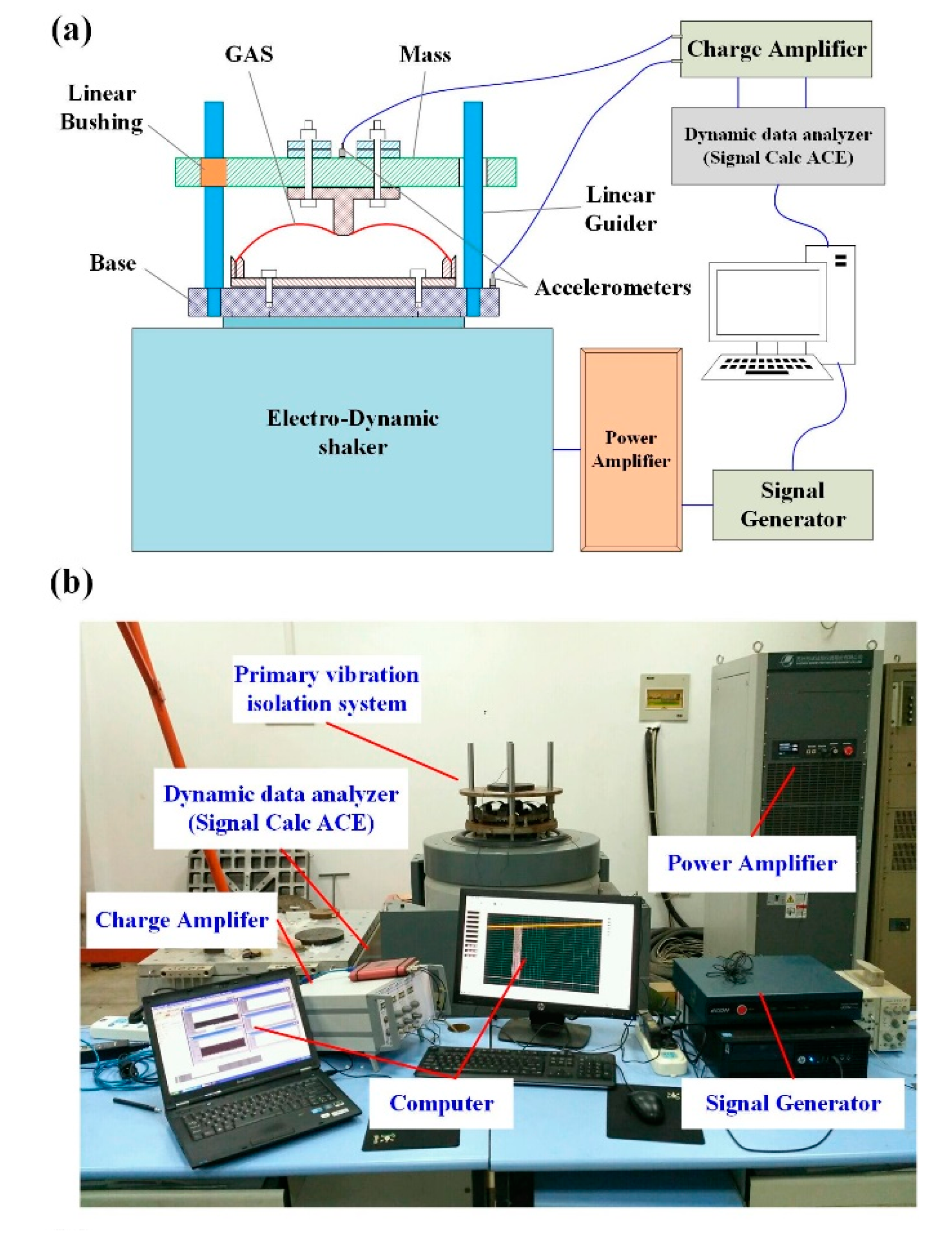
In this paper, the geometric anti-spring isolator with a nonlinear geometric parameter of 0.92 is designed. The spring-steel 60Si2CrVA (Dongguan, China) is used to manufacture blade springs. The actual design parameters of the isolator are shown in Table 4. The photograph of the isolator is shown in Figure 1b. In order to experimentally study the dynamic property of the geometric anti-spring isolator, a single degree of the freedom vibration evaluation system (Figure 8) is established to evaluate the vibration isolation performance of the geometric anti-spring isolator under base excitation.
4.1. Experimental Setup
The single degree of the freedom vibration evaluation system is made up of three parts: the excitation system, the data acquisition system and the primary vibration isolation system. The excitation system is composed of the signal generator, the power amplifier, and the electro-dynamic shaker. The electro-dynamic shaker (DC-4000-40/SC-0808, Suzhou Sushi Testing Instrument Co., Ltd, Suzhou, China) can provide base excitation in the frequency range 1–2000 Hz. Its excitation maximum displacement is 38 mm. The maximum working load and output maximum acceleration are 500 kg and 100 g (1 g = 9.8 m/s2), respectively.
The data acquisition system includes two piezoelectric accelerometers sticking on the load mass and the base, a charge amplifier, a dynamic data analyzer (SignalCalc ACE, Data Physics Corp., San Jose, CA, USA), and personal computers (PC, Lenovo, Beijing, China). The acceleration signals are acquired and post processed by the dynamic data analyzer to obtain the evaluation result of vibration isolation performance.
The primary vibration isolation system is a single-degree-of-freedom system consisted of the geometric anti-spring isolator and load masses. The base is rigidly fixed on the electromagnetic vibration table. Four linear guides are connected to the base to maintain the load mass vertically translational motion through linear bushings. The geometric anti-spring isolator is installed between the base and the load mass with bolts. The load mass is composed of a big cylinder (16 kg) and several small mass blocks. The load mass ranges from 16 kg to 28 kg.
4.2. Discrete Sine Excitation Experiment
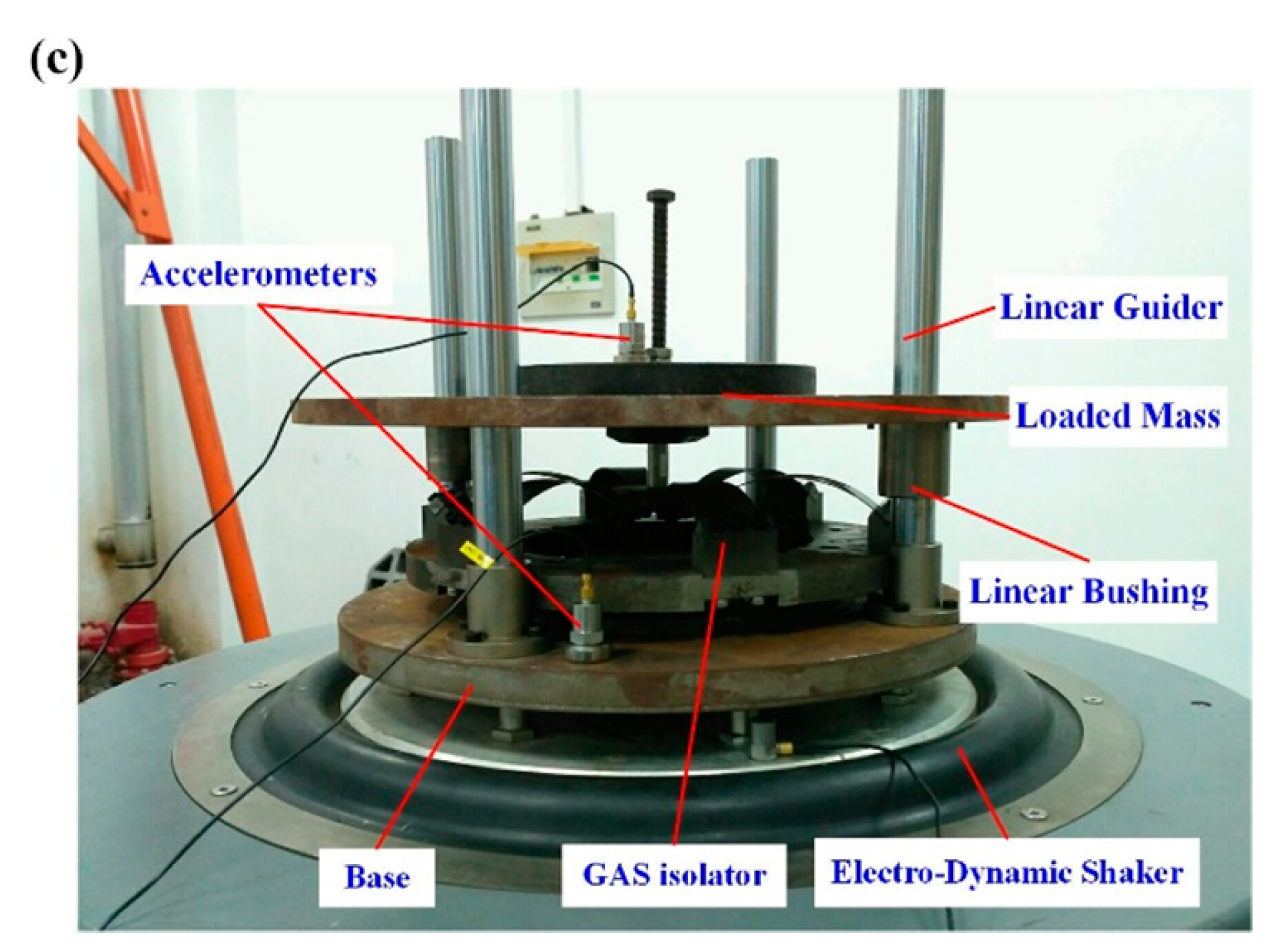
First, the discrete sine excitation signal is used to investigate the vibration isolation performance of the designed geometric anti-spring isolator. The excitation frequency ranges from 1.8 Hz to 10 Hz and increases step by step with a frequency interval of 0.1 Hz. The acceleration signals are acquired by accelerometers after the response signals of the load mass are steady at each discrete excitation frequency. The spectrum of response acceleration is calculated using FFT (Fast Fourier Transform). The acceleration signal at 5 Hz under an excitation displacement amplitude of 0.6 mm is given in Figure 9. Both time history (Figure 9a) and spectrum results (Figure 9b) are presented. It can be seen that the responsive frequency domain signal includes the components of harmonic frequencies. Except for the excitation frequency component of 5 Hz, there exist the frequency components of 10 Hz and 15 Hz, which demonstrates that the nonlinearity exists in the geometric anti-spring isolator.
The acceleration transmissibility curves under different excitation amplitude and different mass load were shown in Figure 9c–d. From the Figure 9c, it is obvious that the transmissibility of the geometric anti-spring isolator under the load mass of 21 kg in resonance area increases with the increment of excitation amplitude. Resonance frequencies under different excitation amplitude are approximate to be 2.4 Hz. When the excitation frequency is larger than 3.6 Hz, transmissibility values of the geometric anti-spring isolator are smaller than 1 and the vibration of load mass is attenuated. When excitation amplitude is 0.8 mm, the acceleration transmissibility is 0.59 (4.5 dB) at the excitation frequency of 4 Hz and 0.11 (19 dB) at the excitation frequency of 8 Hz.
From Figure 9d, it can be seen that an apparent shift of resonance frequency of the geometric anti-spring isolator is observed for different load masses, of which the excitation amplitude is 0.6 mm. The load mass ranges from 16 kg to 26 kg with a mass interval of 2.5 kg. As the mass load increases, the resonance frequency first decreases and then increases. The minimum resonance frequency is 2.4 Hz under the load mass of 21 kg. When the load mass is 21 kg, the vibration isolation performance is better than that of other load masses. However, it can be seen that the attenuation rate of transmissibility slightly grow as load mass goes away from 21 kg. When the excitation frequency is 8 Hz, the transmissibility of the geometric anti-spring isolator for different load masses (16 kg, 18.5 kg, 21 kg, 23.5 kg and 26 kg) is 0.21 (13.6 dB), 0.15 (16.5 dB), 0.12 (18.4 dB) , 0.15 (16.5 dB) and 0.18 (14.9 dB), respectively. These results match well with the change of the resonance frequency of the geometric anti-spring isolator for different load masses.
Figure 9e shows the initial isolation frequency of the geometric anti-spring isolator for different excitation amplitudes and load masses. With the increment of the excitation displacement amplitude, the initial isolation frequency approximately linearly decreases. When the excitation displacement amplitude is 2 mm, the initial isolation frequency reaches to 3.18 Hz. For the situation of different load mass, the initial isolation frequency decreases first and then increases as the load mass increases. The minimum initial isolation frequency under excitation displacement amplitude of 0.6 mm is 3.5 Hz with the load mass of 21 kg.
4.3. Linear Frequency Sweep Excitation Experiment
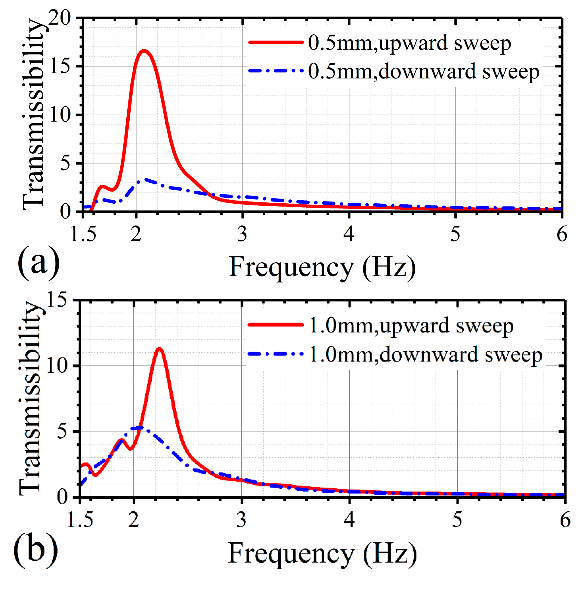
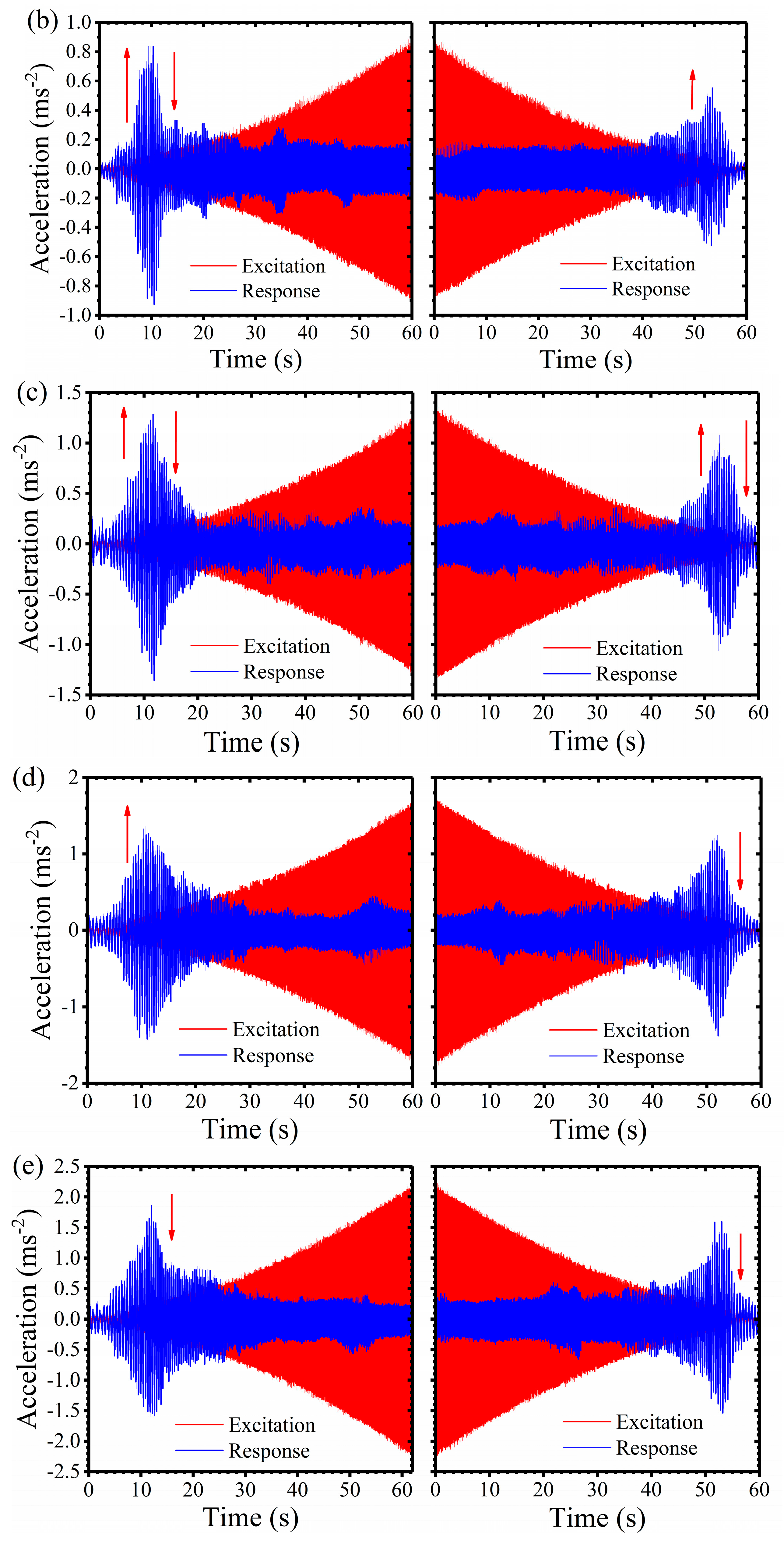
Secondly, linear frequency sweep excitation signals are used to explore the nonlinearity of the designed geometric anti-spring isolator. Here, the low-frequency performance of the geometric anti-spring isolator is our subject. Thus the excitation frequency ranges from 1.5 Hz to 6 Hz and each sweep excitation experiment lasts 60 s once. Both upward and downward frequency sweep excitation experiments are carried out. Time history signals of both excitation acceleration and response acceleration under different excitation amplitudes are shown in Figure 10.
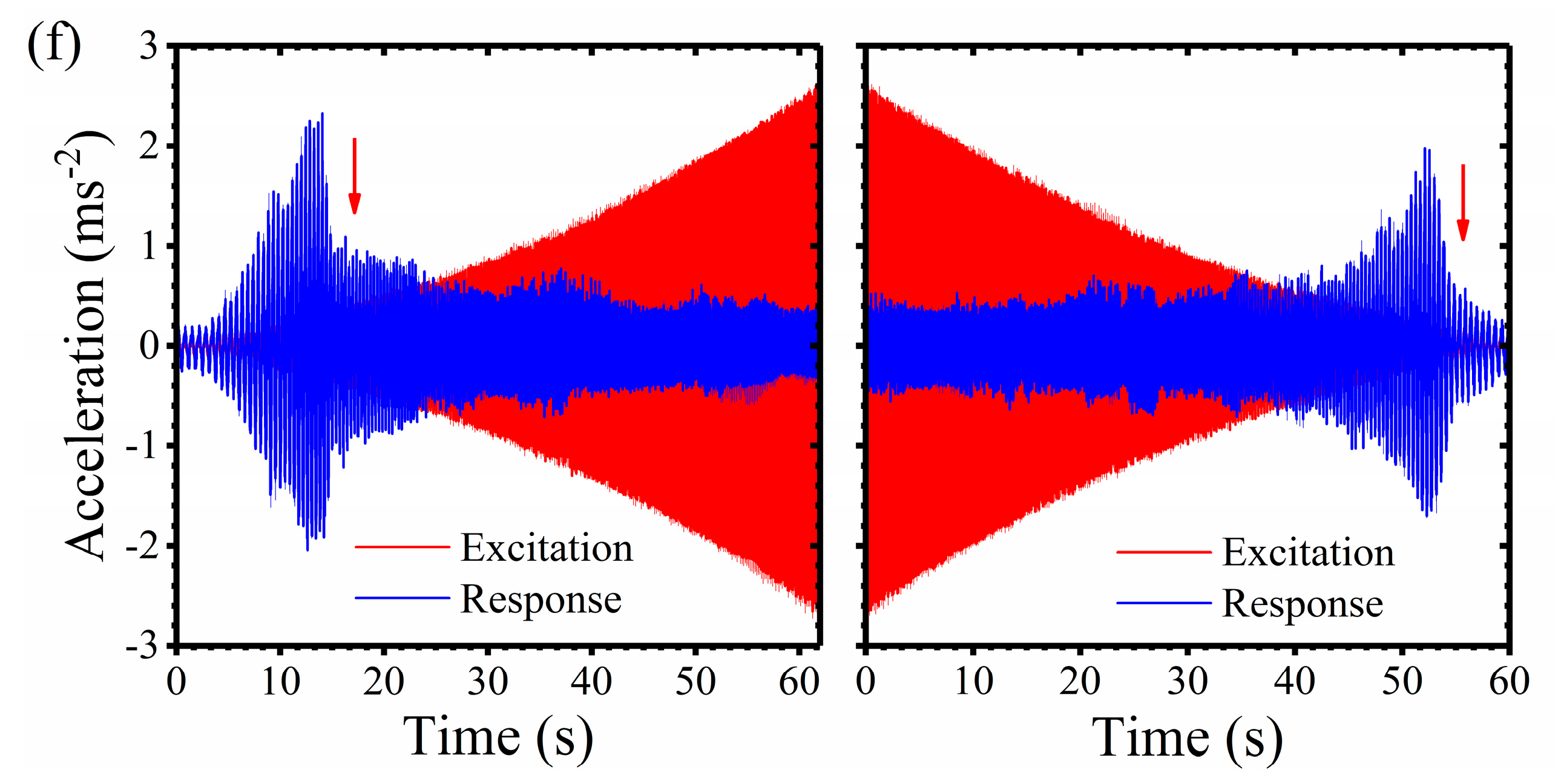
With the growth of excitation amplitude, the acceleration response peak increases. Nonlinear jump phenomena are observed and vary with the increment of the excitation displacement amplitude. In Figure 10a, under the displacement excitation of 0.5 mm, both upward jumping and downward jumping phenomena of the response amplitude of load mass occurs in the neighbor of the resonance area under the upward frequency sweep excitation. For the situation of the downward frequency sweep excitation, only a downward jumping phenomena of the response signal is observed, which demonstrates a softening-type stiffness characteristic. When the excitation amplitude is 1.0 mm (Figure 10b), both the upward jumping and downward jumping phenomena of the response signal of the load mass exists under the upward frequency sweep excitation, which shows both hardening-type and softening-type nonlinearity. However, only upward jumping phenomenon of the response signal is found under the downward frequency sweep excitation. When the excitation amplitude is 1.5 mm, both the upward jumping and downward jumping phenomena are observed under upward and downward frequency sweep excitation. When the excitation amplitude increases to 2 mm, the nonlinearity is weak. There exists an upward jumping phenomenon under the upward frequency sweep excitation and a downward jumping phenomenon under the downward frequency sweep excitation, which demonstrates that the designed isolator has a softening-type stiffness characteristic. When the excitation amplitude is 2.5 mm or 3 mm, the response signals under both upward and downward frequency sweep excitation show an obvious downward jumping phenomenon. It can be seen that the designed isolator shows a complex nonlinearity. When the excitation amplitude is changed, both the hardening-type and softening-type stiffness characteristic can be observed.
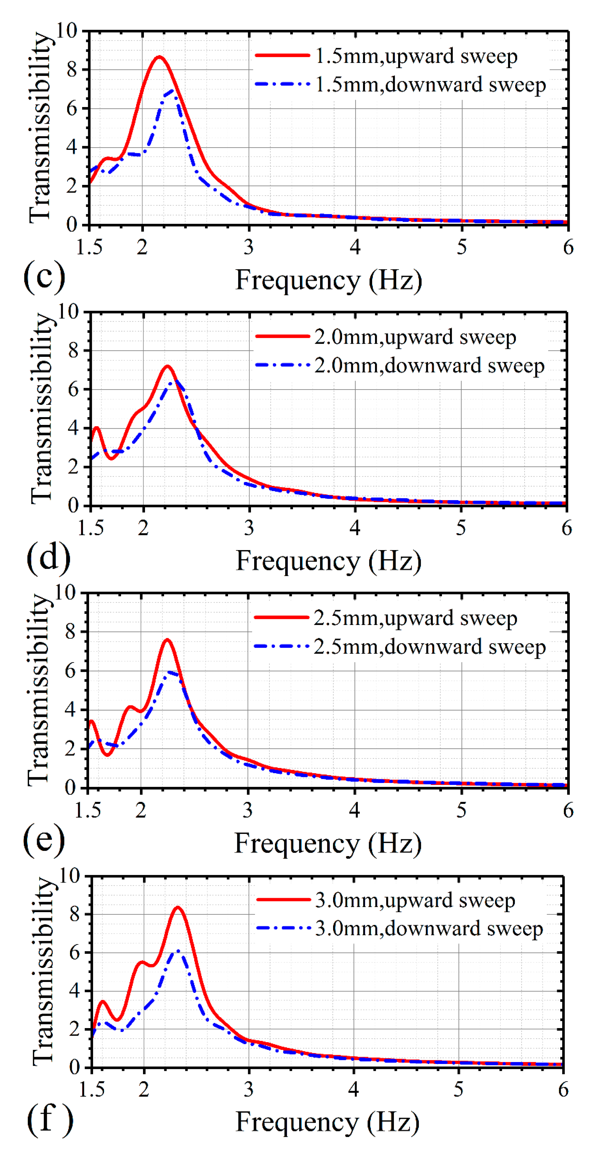
According to the acceleration signals in time domain, the acceleration transmissibility curve (Figure 11) of the geometric anti-spring isolator under the frequency sweep excitation can be calculated using the FFT transform. From Figure 11, it can be seen that the transmissibility curves show much difference in the resonance area between upward and downward frequency sweep excitation. The peak of the transmissibility curve under upward frequency sweep excitation is larger than that under downward frequency sweep excitation for all the excitation levels, which demonstrates that the designed geometric anti-spring isolator possesses a global hardening-type stiffness characteristic on the whole. The resonance frequency increases with the increment of the excitation amplitude. However, for different excitation amplitude, the characteristic of transmissibility shows obvious differences. As the excitation amplitude increases, the difference of transmissibility curve between the upward and downward frequency sweep excitation reduces first. When the excitation amplitude is 2 mm, the transmissibility curves for the upward and downward sweep are almost the same. When the excitation amplitude is larger than 2 mm, as the excitation amplitude increases, the difference of transmissibility between the upward and downward frequency sweep is enlarged. This is because that the type of nonlinearity of the geometric anti-spring isolator changes from a softening type stiffness characteristic to a hardening type stiffness characteristic with the increment of excitation amplitude, and when the excitation amplitude is close to 2 mm, the designed geometric anti-spring isolator approximately becomes a linear isolator.
5. Conclusions
In this paper, a geometric anti-spring isolator made up of several cantilever blade springs is developed. The idea of optimization based on the genetic algorithm is utilized to mathematically solve the differential boundary problem of static mechanical of the geometric anti-spring isolation structure. The dimensionless optimal design parameters of geometric anti-spring isolation structure for different nonlinear geometric parameters are achieved. A Matlab/Simulink program is used to explore the transmissibility of the geometric anti-spring isolator under base excitation. The effects of the nonlinear geometric parameter, excitation displacement amplitude, load weight and damping on the transmissibility of the geometric anti-spring isolator are discussed. A single degree of the freedom vibration evaluation system is established to investigate the vibration isolation performance and nonlinearity characteristics of the geometric anti-spring isolator with a nonlinear geometric parameter of 0.92. Discrete sine excitation experiment and linear frequency sweep excitation experiment are carried out. The initial isolation frequency is used to describe the low-frequency vibration isolation range of the isolator. Some conclusions are as follows:
(1) The nonlinear geometric parameter i.e., the dimensionless horizontal coordinate of blades spring’s vertex is the key parameter to decide the mechanical property of the geometric anti-spring isolator. With the decrement of the nonlinear geometric parameter, the dynamic stiffness of the isolator decreases quickly. When the nonlinear geometric parameter is 0.9027, the minimum dynamic stiffness approaches zero.
(2) The geometric anti-spring isolator under the rated load has a hardening-type stiffness characteristic. As the excitation amplitude increases, the nonlinearity of the isolator enhances.
(3) The imperfection of load weight will largely change the resonance frequency and nonlinearity characteristic of the geometric anti-spring isolator. When the working load goes away from the rated load, the resonance frequency of the geometric anti-spring isolator increases and the nonlinearity type of the isolator varies with the increment of the excitation amplitude. When the excitation amplitude is small, the isolator shows a softening-type stiffness characteristic. When the excitation amplitude is large, the isolator shows a hardening-type stiffness characteristic.
(4) By increasing the damping, the nonlinearity of the isolator will be weakened. The attenuation rate in the isolation area does not change if the damping is not too large.
(5) The experiment shows that the designed isolator has good low-frequency isolation performance. Under the rated working load, the initial isolation frequency is not larger than 3.6 Hz. With the excitation amplitude increases, the initial isolation frequency of the isolator decreases linearly. When the working load is changed, the initial isolation frequency will be enlarged. In the frequency sweep excitation experiment, both upward jumping and downward jumping phenomena are observed, which demonstrates that the geometric anti-spring isolator had complex nonlinearity characteristics when damping is light. The nonlinearity characteristics of the geometric anti-spring isolator vary as the excitation amplitude increases.
Acknowledgments
The authors disclosed receipt of the following financial support for the research, authorship, and/or publication of this article: Financial support from the Chinese Academy of Sciences (Grant No. XDB22040502) was gratefully acknowledged. This study was also supported by the Collaborative Innovation Center of Suzhou Nano Science and Technology.
Author Contributions
The idea was proposed by Xinglong Gong and he gave suggestions about the experimental design. Lixun Yan completed the experiment and mathematically simulation and wrote the manuscript. Both authors discussed the results and revised the manuscript.
Conflicts of Interest
The authors declare no conflict of interest.
References
- Ibrahim, R.A. Recent advances in nonlinear passive vibration isolators. J. Sound Vib. 2008, 314, 371–452. [Google Scholar] [CrossRef]
- Carrella, A.; Brennan, M.J.; Waters, T.P. Static analysis of a passive vibration isolator with quasi-zero-stiffness characteristic. J. Sound Vib. 2007, 301, 678–689. [Google Scholar] [CrossRef]
- Carrella, A.; Brennan, M.J.; Waters, T.P. Optimization of a quasi-zero-stiffness isolator. J. Mech. Sci. Technol. 2007, 21, 946–949. [Google Scholar] [CrossRef]
- Carrella, A.; Brennan, M.J.; Waters, T.P.; Lopes, V. Force and displacement transmissibility of a nonlinear isolator with high-static-low-dynamic-stiffness. Int. J. Mech. Sci. 2012, 55, 22–29. [Google Scholar] [CrossRef]
- Ahn, H.-J. Performance limit of a passive vertical isolator using a negative stiffness mechanism. J. Mech. Sci. Technol. 2008, 22, 2357–2364. [Google Scholar] [CrossRef]
- Le, T.D.; Ahn, K.K. A vibration isolation system in low frequency excitation region using negative stiffness structure for vehicle seat. J. Sound Vib. 2011, 330, 6311–6335. [Google Scholar] [CrossRef]
- Le, T.D.; Bui, M.T.N.; Ahn, K.K. Improvement of vibration isolation performance of isolation system using negative stiffness structure. IEEE/ASME Trans. Mechatron. 2016, 21, 1561–1571. [Google Scholar] [CrossRef]
- Hao, Z.; Cao, Q. The isolation characteristics of an archetypal dynamical model with stable-quasi-zero-stiffness. J. Sound Vib. 2015, 340, 61–79. [Google Scholar] [CrossRef]
- Lan, C.C.; Yang, S.A.; Wu, Y.S. Design and experiment of a compact quasi-zero-stiffness isolator capable of a wide range of loads. J. Sound Vib. 2014, 333, 4843–4858. [Google Scholar] [CrossRef]
- Huang, X.C.; Liu, X.T.; Sun, J.Y.; Zhang, Z.Y.; Hua, H.X. Vibration isolation characteristics of a nonlinear isolator using euler buckled beam as negative stiffness corrector: A theoretical and experimental study. J. Sound Vib. 2014, 333, 1132–1148. [Google Scholar] [CrossRef]
- Huang, X.C.; Liu, X.T.; Hua, H.X. Effects of stiffness and load imperfection on the isolation performance of a high-static-low-dynamic-stiffness non-linear isolator under base displacement excitation. Int. J. Non-Linear Mech. 2014, 65, 32–43. [Google Scholar] [CrossRef]
- Shaw, A.D.; Neild, S.A.; Friswell, M.I. Relieving the effect of static load errors in nonlinear vibration isolation mounts through stiffness asymmetries. J. Sound Vib. 2015, 339, 84–98. [Google Scholar] [CrossRef]
- Zhou, N.; Liu, K. A tunable high-static-low-dynamic stiffness vibration isolator. J. Sound Vib. 2010, 329, 1254–1273. [Google Scholar] [CrossRef]
- Wu, W.J.; Chen, X.D.; Shan, Y.H. Analysis and experiment of a vibration isolator using a novel magnetic spring with negative stiffness. J. Sound Vib. 2014, 333, 2958–2970. [Google Scholar] [CrossRef]
- Shin, K. On the performance of a single degree-of-freedom high-static-low-dynamic stiffness magnetic vibration isolator. Int. J. Precis. Eng. Man. 2014, 15, 439–445. [Google Scholar] [CrossRef]
- Carrella, A.; Brennan, M.J.; Waters, T.P.; Shin, K. On the design of a high-static-low-dynamic stiffness isolator using linear mechanical springs and magnets. J. Sound Vib. 2008, 315, 71–720. [Google Scholar] [CrossRef]
- Xu, D.L.; Yu, Q.P.; Zhou, J.X.; Bishop, S.R. Theoretical and experimental analyses of a nonlinear magnetic vibration isolator with quasi-zero-stiffness characteristic. J. Sound Vib. 2013, 332, 3377–3389. [Google Scholar] [CrossRef]
- Zheng, Y.; Zhang, X.; Luo, Y.; Yan, B.; Ma, C. Design and experiment of a high-static-low-dynamic stiffness isolator using a negative stiffness magnetic spring. J. Sound Vib. 2016, 360, 31–52. [Google Scholar] [CrossRef]
- Zhu, T.; Cazzolato, B.; Robertson, W.S.P.; Zander, A. Vibration isolation using six degree-of-freedom quasi-zero stiffness magnetic levitation. J. Sound Vib. 2015, 358, 48–73. [Google Scholar] [CrossRef]
- Huang, X.C.; Liu, X.T.; Hua, H.X. On the characteristics of an ultra-low frequency nonlinear isolator using sliding beam as negative stiffness. J. Mech. Sci. Technol. 2014, 28, 813–822. [Google Scholar] [CrossRef]
- Shaw, A.D.; Neild, S.A.; Wagg, D.J.; Weaver, P.M.; Carrella, A. A nonlinear spring mechanism incorporating a bistable composite plate for vibration isolation. J. Sound Vib. 2013, 332, 6265–6275. [Google Scholar] [CrossRef]
- Sun, X.; Jing, X.; Xu, J.; Cheng, L. Vibration isolation via a scissor-like structured platform. J. Sound Vib. 2014, 333, 2404–2420. [Google Scholar] [CrossRef]
- Araki, Y.; Kimura, K.; Asai, T.; Masui, T.; Omori, T.; Kainuma, R. Integrated mechanical and material design of quasi-zero-stiffness vibration isolator with superelastic Cu-Al-Mn shape memory alloy bars. J. Sound Vib. 2015, 358, 74–83. [Google Scholar] [CrossRef]
- Bertolini, A.; Cella, G.; DeSalvo, R.; Sannibale, V. Seismic noise filters, vertical resonance frequency reduction with geometric anti-springs: A feasibility study. Nucl. Instrum. Methods Phys. Res. Sect. A 1999, 435, 475–483. [Google Scholar] [CrossRef]
- Cella, G.; Sannibale, V.; DeSalvo, R.; Marka, S.; Takamori, A. Monolithic geometric anti-spring blades. Nucl. Instrum. Methods Phys. Res. Sect. A 2005, 540, 502–519. [Google Scholar] [CrossRef]
- Bertolinic, A.; Cella, G.; Chenyang, W.; de Salvo, R.; Kovalik, J. Recent progress on the r&d program of the seismic attenuation system (sas) proposed for the advanced gravitational wave detector, LIGO II. Nucl. Instrum. Methods Phys. Res. Sect. A 2001, 461, 300–303. [Google Scholar] [CrossRef]
- DeSalvo, R. Passive, nonlinear, mechanical structures for seismic attenuation. J. Comput. Nonlinear Dyn. 2007, 2, 290–298. [Google Scholar] [CrossRef]
- Blom, M.R.; Beker, M.G.; Bertolini, A.; van den Brand, J.F.J.; Bulten, H.J.; Hennes, E.; Mul, F.A.; Rabeling, D.S.; Schimmel, A. Seismic attenuation system for the external injection bench of the advanced Virgo gravitational wave detector. Nucl. Instrum. Methods Phys. Res. Sect. A 2013, 718, 466–470. [Google Scholar] [CrossRef]
Figure 1.
The model of the geometric anti-spring isolator. (a) Schematic of the geometric anti-spring isolator. (b) Photograph of the geometric anti-spring isolator. (c) Cross-section diagrams of the geometric anti-spring isolator. (d) The shape of the cantilever blade spring. (e) One dimension mechanical model of the blade spring.
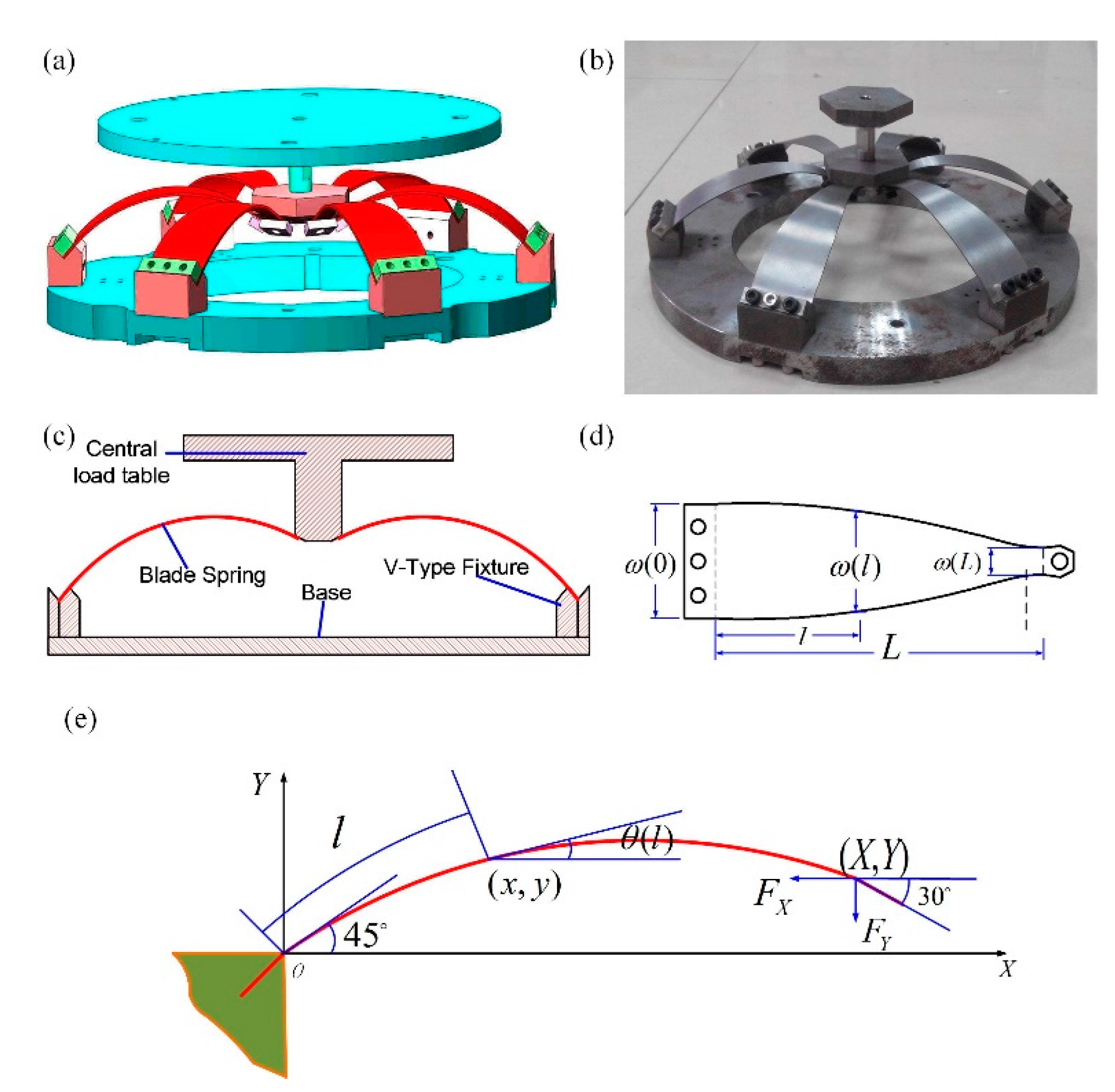
Figure 2.
The flow chart of the genetic algorithm to solve the boundary problem.

Figure 3.
Dimensionless theoretically numerical result of the geometric anti-spring isolator. (a) Dimensionless vertical force. (b) Dimensionless vertical stiffness vs. vertical coordinate. (c) Dimensionless vertical stiffness vs. vertical force.
Figure 3.
Dimensionless theoretically numerical result of the geometric anti-spring isolator. (a) Dimensionless vertical force. (b) Dimensionless vertical stiffness vs. vertical coordinate. (c) Dimensionless vertical stiffness vs. vertical force.


Figure 4.
Dimensionless vertical force (a) and stiffness characteristic at the optimal working point (b) of the geometric anti-spring isolator.
Figure 4.
Dimensionless vertical force (a) and stiffness characteristic at the optimal working point (b) of the geometric anti-spring isolator.
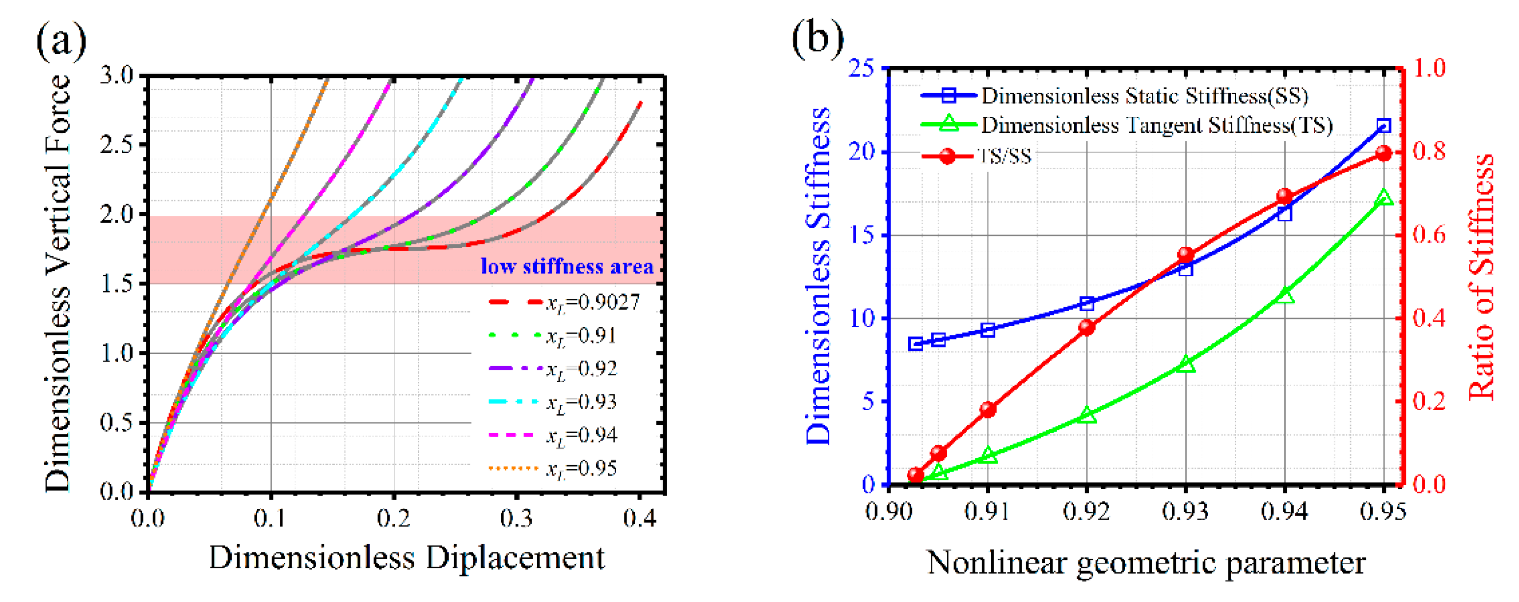
Figure 5.
The mathematical simulation program. (a) The simulation model under harmonic displacement excitation. (b) The simulation model of the nonlinear restoring force.
Figure 5.
The mathematical simulation program. (a) The simulation model under harmonic displacement excitation. (b) The simulation model of the nonlinear restoring force.
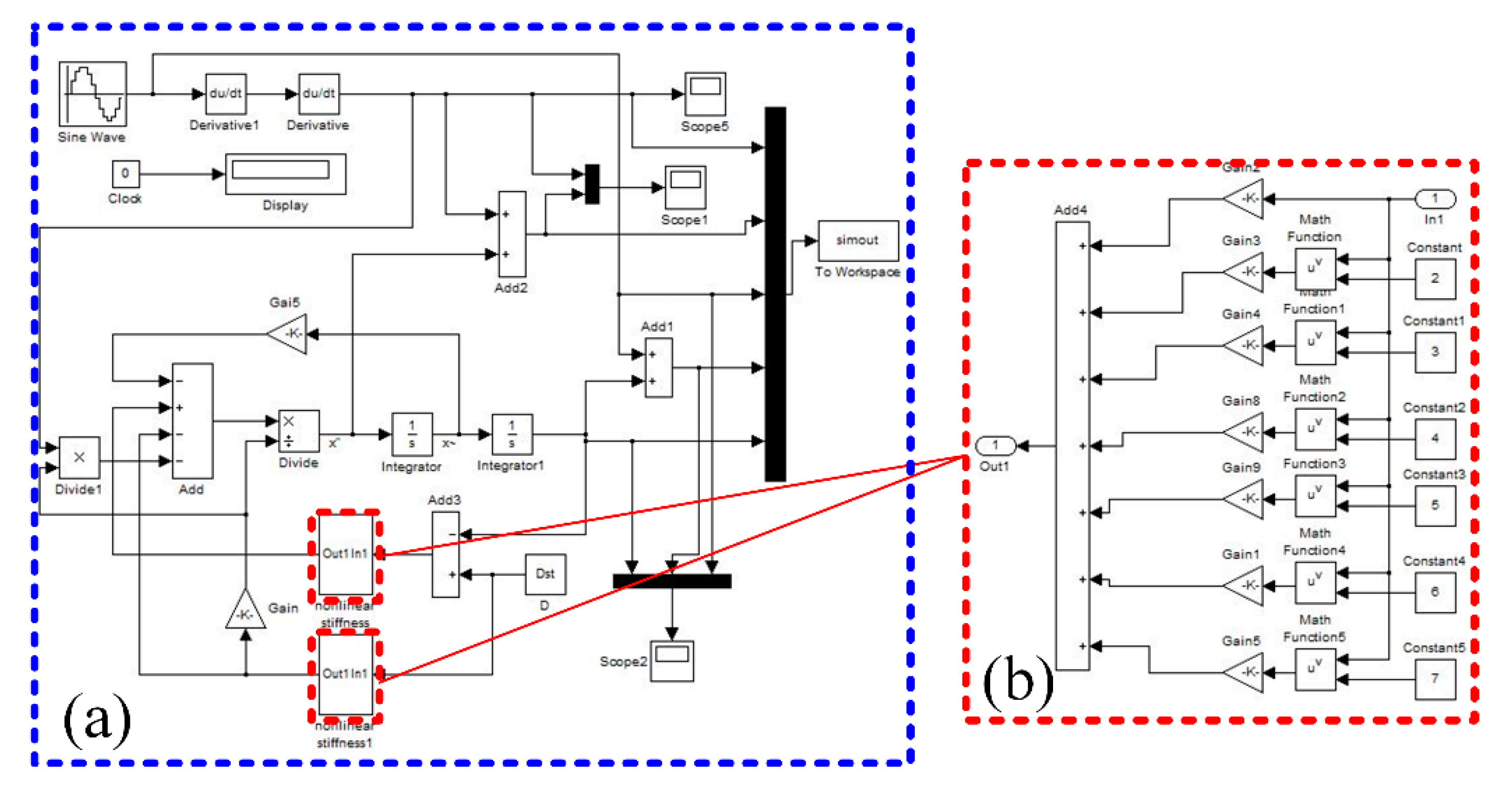
Figure 6.
The mathematical simulation results. (a) Transmissibility for different nonlinear geometric parameters at the rated load. (b) Transmissibility for different excitation displacement amplitudes. (c) Transmissibility for different load weights. (d) Transmissibility for different damping ratios.

Figure 7.
The influence of load weight on the transmissibility of the isolator. (a) The dimensionless load weight is 1.34. (b) The dimensionless load weight is 1.55. (c) The dimensionless load weight is 1.96. (d) The dimensionless load weight is 2.08.
Figure 7.
The influence of load weight on the transmissibility of the isolator. (a) The dimensionless load weight is 1.34. (b) The dimensionless load weight is 1.55. (c) The dimensionless load weight is 1.96. (d) The dimensionless load weight is 2.08.

Figure 8.
Dynamic experimental system for the geometric anti-spring isolator. (a) Schematic of the dynamic experimental setup; (b) Photograph of the dynamic experimental setup; (c) Photograph of the primary vibration isolation system.
Figure 8.
Dynamic experimental system for the geometric anti-spring isolator. (a) Schematic of the dynamic experimental setup; (b) Photograph of the dynamic experimental setup; (c) Photograph of the primary vibration isolation system.


Figure 9.
The results of discrete sinusoidal excitation experiment. (a) The time domain signal at 5 Hz with excitation displacement of 0.6 mm. (b) The frequency domain signal at 5 Hz with excitation displacement of 0.6 mm. (c) Acceleration transmissibility for different excitation amplitudes: m = 21 kg. (d) Acceleration transmissibility for different mass loads with excitation amplitude of 0.6mm. (e) The initial isolation frequency of the isolator.

Figure 10.
Time history signals of acceleration under linear sinusoidal sweep excitation. (a) Excitation displacement amplitude: B = 0.5 mm. (b) B = 1.0 mm. (c) B = 1.5 mm. (d) B = 1.5 mm. (e) B = 2.5 mm. (f) B = 3.0 mm.
Figure 10.
Time history signals of acceleration under linear sinusoidal sweep excitation. (a) Excitation displacement amplitude: B = 0.5 mm. (b) B = 1.0 mm. (c) B = 1.5 mm. (d) B = 1.5 mm. (e) B = 2.5 mm. (f) B = 3.0 mm.
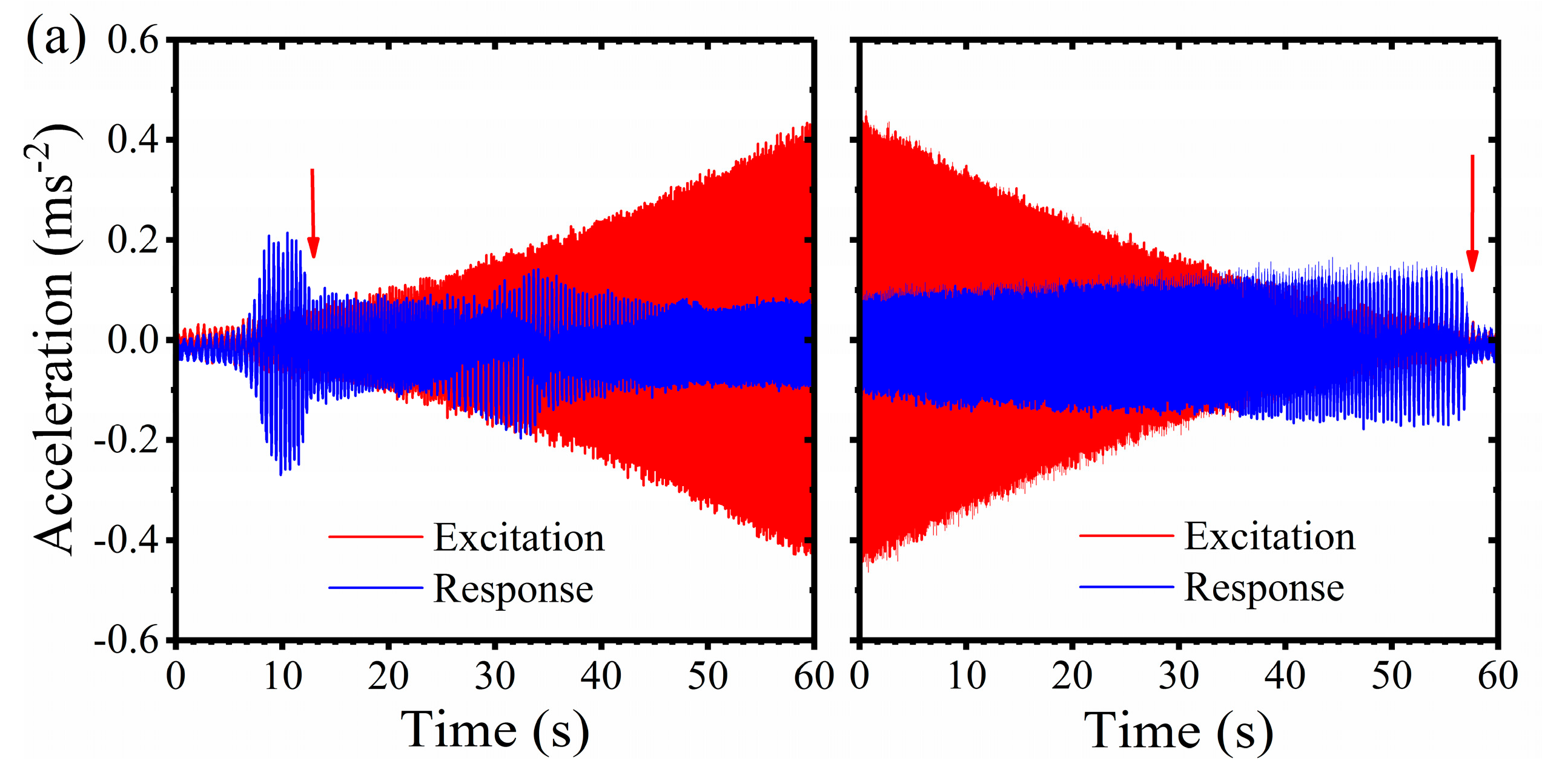


Figure 11.
Acceleration transmissibility of the geometric anti-spring isolator under linear frequency sweep excitation with different excitation displacement amplitudes. The excitation displacement are: (a) 0.5 mm, (b) 1.0 mm, (c) 1.5 mm, (d) 2.0 mm, (e) 2.5 mm and (f) 3.0 mm, respectively.
Figure 11.
Acceleration transmissibility of the geometric anti-spring isolator under linear frequency sweep excitation with different excitation displacement amplitudes. The excitation displacement are: (a) 0.5 mm, (b) 1.0 mm, (c) 1.5 mm, (d) 2.0 mm, (e) 2.5 mm and (f) 3.0 mm, respectively.


Table 1.
The optional parameters of genetic algorithm function ga().
| Options | Value |
|---|---|
| PlotFcns | @gaplotbestf |
| Generations | 200 |
| CrossoverFraction | 0.2 |
| InitialPopulation | −2.0 |
| MutationFcn | @mutationadaptfeasible |
| TolFun | 1 × 10⁻¹² |
Table 2.
The dimensionless minimum stiffness and angular frequency.
| 0.95 | 0.060727 | −1.920 | 17.18 | 8.95 |
| 0.94 | 0.067876 | −1.830 | 11.27 | 6.16 |
| 0.93 | 0.07429 | −1.780 | 7.17 | 4.03 |
| 0.92 | 0.081354 | −1.750 | 4.12 | 2.36 |
| 0.91 | 0.083767 | −1.751 | 1.72 | 0.98 |
| 0.9027 | 0.085627 | −1.753 | 0.22 | 0.13 |
Table 3.
Coefficients in the polynomial fitting function of restoring force.
| 0.9027 | 35.20 | −329.85 | 1991.34 | −8291.93 | 22,022.09 | −32,194.61 | 19,948.43 |
| 0.91 | 32.63 | −298.54 | 1808.39 | −7651.96 | 21,186.12 | −32,719.64 | 21,726.28 |
| 0.92 | 29.91 | −264.02 | 1660.20 | −7494.34 | 23,193.40 | −40,935.25 | 31,675.37 |
| 0.93 | 28.50 | −240.06 | 1632.69 | −8239.71 | 30,027.20 | −63,475.03 | 59,488.88 |
| 0.94 | 28.86 | −222.00 | 1593.47 | −8398.50 | 34,082.22 | −82,434.32 | 91,965.84 |
| 0.95 | 32.09 | −219.61 | 1689.49 | −8845.06 | 37,265.10 | −92,945.24 | 11,4202.6 |
Table 4.
The actual design parameter of the geometric anti-spring isolator.
| Parameter | Value |
|---|---|
| Base width | 36 mm |
| Effective length | 120 mm |
| Thickness | 0.78 mm |
| Yield strength | 1665 MPa |
| Young’s modulus | 196 GPa |
© 2017 by the authors. Licensee MDPI, Basel, Switzerland. This article is an open access article distributed under the terms and conditions of the Creative Commons Attribution (CC BY) license (http://creativecommons.org/licenses/by/4.0/).
Share and Cite
MDPI and ACS Style
Yan, L.; Gong, X. Experimental Study of Vibration Isolation Characteristics of a Geometric Anti-Spring Isolator. Appl. Sci. 2017, 7, 711. https://doi.org/10.3390/app7070711
AMA Style
Yan L, Gong X. Experimental Study of Vibration Isolation Characteristics of a Geometric Anti-Spring Isolator. Applied Sciences. 2017; 7(7):711. https://doi.org/10.3390/app7070711
Chicago/Turabian StyleYan, Lixun, and Xinglong Gong. 2017. "Experimental Study of Vibration Isolation Characteristics of a Geometric Anti-Spring Isolator" Applied Sciences 7, no. 7: 711. https://doi.org/10.3390/app7070711
Note that from the first issue of 2016, this journal uses article numbers instead of page numbers. See further details here.