Experimental Study on Robustness of an Eddy Current-Tuned Mass Damper


1
Key Laboratory for Metallurgical Equipment and Control of Ministry of Education, Wuhan University of Science and Technology, Wuhan 430081, China
2
Hubei Key Laboratory of Mechanical Transmission and Manufacturing Engineering, Wuhan University of Science and Technology, Wuhan 430081, China
3
Smart Materials and Structures Laboratory, Department of Mechanical Engineering, University of Houston, Houston, TX 77204, USA
4
Key Laboratory for Bridge and Wind Engineering of Hunan Province, College of Civil Engineering, Hunan University, Changsha 410082, China
*
Authors to whom correspondence should be addressed.
Appl. Sci. 2017, 7(9), 895; https://doi.org/10.3390/app7090895
Submission received: 3 August 2017
/
Revised: 25 August 2017
/
Accepted: 28 August 2017
/
Published: 1 September 2017
(This article belongs to the Special Issue Development and Application of Nonlinear Dissipative Device in Structural Vibration Control)
Abstract
:In this paper, an eddy current tuned mass damper (ECTMD) is utilized to control the vibration of a cantilever beam. The robustness of the ECTMD against frequency detuning is experimentally studied in cases of both free vibration and forced vibration. The natural frequency of the cantilever beam can be adjusted by changing the location of a lumped mass. For purposes of comparison with the ECTMD, the robustness of a tuned mass damper (TMD) is also studied. The experimental results in the free vibration case indicate that the ECTMD works well both in tuned and detuned situations, and the equivalent damping ratio of the cantilever beam equipped with the ECTMD is 2.08~5.91 times that of the TMD. However, the TMD only suppresses the free vibration effectively in the tuned situation. With forced vibration, the experimental results also demonstrate the robustness of the ECTMD in vibration suppression in detuned cases. On the other hand, the cantilever beam with TMD experiences 1.63~2.99 times the peak vibration of that of the ECTMD control.
1. Introduction
Vibration control is commonly used in civil engineering [1,2,3,4,5], and includes passive [6,7], semi-active [8,9,10] and active approaches [11,12,13]. In the passive approach, dampers, such as magneto-rheological dampers, fluid viscous dampers, particle dampers and tuned mass dampers (TMDs), have been utilized to suppress structural vibration and dissipate vibration energy of the controlled structures [14,15,16,17,18,19,20,21,22,23,24]. A typical TMD device mainly consists of a spring-mass system and a damper, with mainly the spring-mass-damper model usually being used to investigate the characteristics of TMDs [25,26,27]. When the frequency of the TMD is tuned to the same as that of the controlled structure, the vibration energy of the controlled structure is transferred to the TMD through the spring-mass system and is dissipated by the damper. Owing to their simplicity and effectiveness, TMDs are widely employed in vibration control for bridges [28,29,30,31,32], high-rise buildings [33,34,35], and so on. However, TMDs are sensitive to frequency detuning, i.e., when the natural frequency of the primary structure is changed, the control performance of TMD will be degraded.
Recently, eddy current dampers (ECDs) have been proposed to suppress structural vibration, and the control effectiveness of ECDs has been demonstrated both experimentally and numerically [36,37]. ECDs can generate an electromagnetic force to hinder structural movement and dissipate energy through eddy currents, which are induced when an electrical conductor moves through a stationary magnetic field or vice versa. The damping force provided by ECDs mainly depends on the relative moving speed between the conductor and the magnetic field, the strength of the magnetic field, and the gap between the magnet and conductor [38]. Various applications for the use of ECDs for controlling structural vibrations have been studied. Bae et al. [39] investigated the performance of an ECD on vibration control of a cantilever beam. A theoretical model of the ECD was established based on electromagnetic theory, and this model was validated by experiments. Zhang et al. [40] proposed a novel planar ECD that can provide damping forces in two different directions, and the analytical model for simulation of the proposed planar ECD was validated by experiments. Bae et al. [41] applied an ECD to provide additional damping for a tuned mass damper system on the vibration control of a large-scale beam structure, and the feasibility of applying the ECD in the vibration control of large structures was verified. Ao and Reynolds [42] used an ECD to control the vibration of a footbridge and the analytic results demonstrated that the damping provided by the ECD was enhanced under both harmonic and random inputs.
More recently, eddy current tuned mass dampers (ECTMDs), which combine a traditional TMD and an ECD, have been proposed to control undesirable vibrations. Based on the theories of mechanics and electromagnetism, the behaviors of ECTMDs have been studied by many researchers [37,38,39,40,41]. Niu et al. [43] applied an ECTMD on a bridge to suppress the wind-induced vibrations that occur in the bridge hangers. Lu et al. [44] investigated the vibration suppression performance of an ECTMD in Shanghai Center Tower, and the experimental results showed that the acceleration resulting from wind-induced vibration was reduced by 45–60%.
The feasibility and effectiveness of ECTMDs in vibration control has been demonstrated by the aforementioned studies. However, the robustness of ECTMDs has rarely been reported, especially in cases of experimental studies. In this paper, the robustness of an ECTMD against frequency detuning was studied experimentally in cases of both free vibration and forced vibration. Furthermore, the robustness of a traditional TMD was also studied to make a comparison with the ECTMD.
2. Vibration Control of a Cantilever Beam with an Eddy Current Tuned Mass Damper
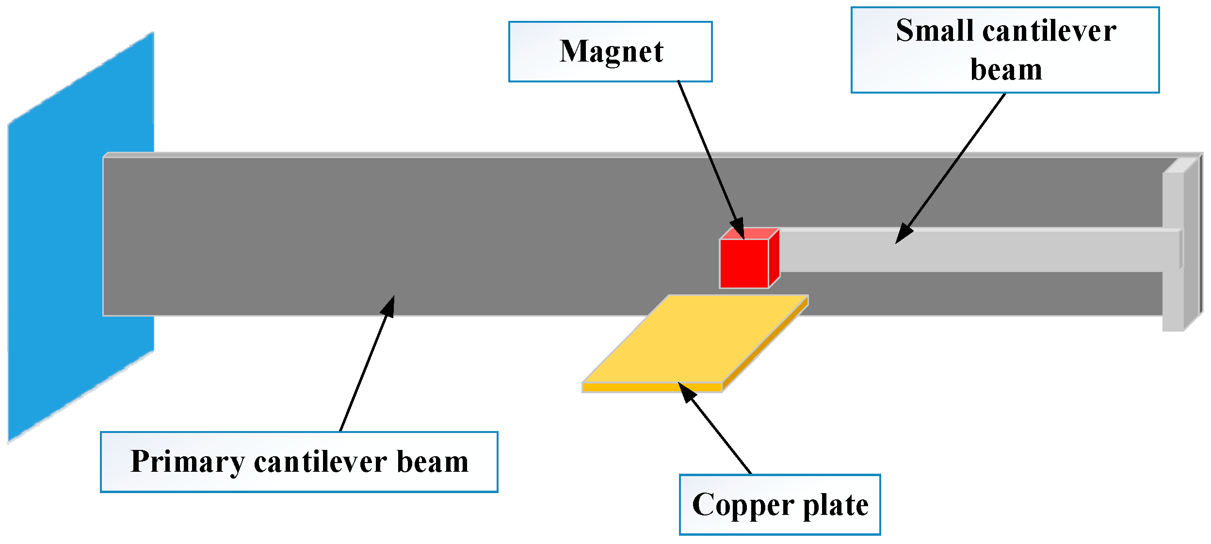
In this paper, a cantilever beam is used as the primary structure, and an ECTMD is installed on the end of the primary cantilever beam, as shown in Figure 1, to control the vibration of the beam. The ECTMD consists of a small cantilever beam, a permanent magnet and a copper plate fixed on the primary cantilever beam. The small cantilever beam can provide stiffness for the ECTMD and the frequency of the ECTMD can be adjusted by changing the length of the beam. The permanent magnet is placed on the end of the small cantilever beam, and can be regarded as a lumped mass. In this study, the ECTMD or TMD is designed to control the first mode vibration of the primary cantilever beam. When the primary cantilever beam is excited by external forces, the vibration energy can be transferred through the small cantilever beam to the ECTMD.
To investigate the robustness of the ECTMD, the natural frequency of the cantilever beam is designed to be a variable, while the natural frequencies of the TMD and ECTMD are fixed. When the natural frequency of the cantilever beam is set close to the natural frequency of the ECTMD or the TMD, it is defined as a perfectly tuned situation; the opposite conditions are defined as a detuned situation. To study the detuned influence on the robustness of the ECTMD and TMD, the detuned ratio γ is defined by
where fp is the fundamental natural frequency of the cantilever beam, and fdamp is the natural frequency of the damper. When the detuned ratio γ is less than zero, this situation is defined as downward-detuned; and if the detuned ratio γ is larger than zero, it is defined as upward-detuned.
3. Experimental Setup
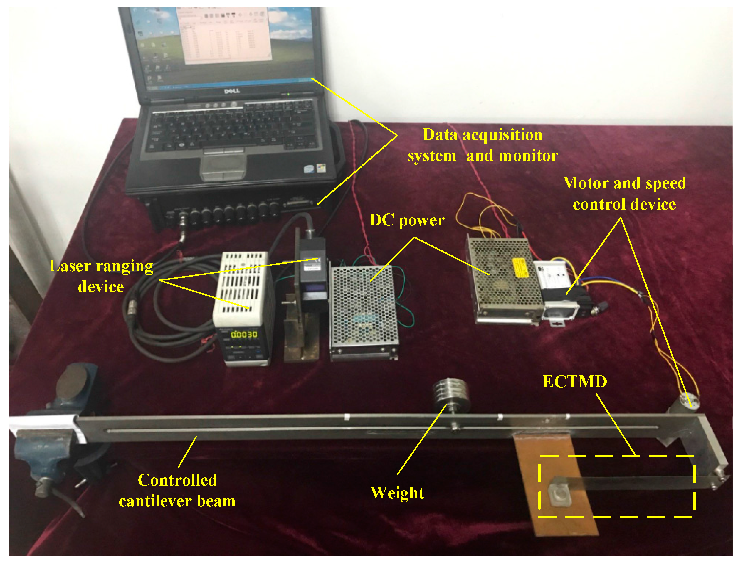
The experimental setup is shown in Figure 2. A data acquisition system with 16-bit resolution and 1 MHz maximum repeat rate (IOtech WaveBook 516) is used to collect data and a laser displacement sensor with 0.6 μm repeatability, 150 mm reference distance and ±40 mm measurement range (Keyence LK-G155H) is used to record the displacement of the primary cantilever beam. A vibration exciting motor with an unbalanced mass (WS-25GA370R) is used to generate a harmonic excitation on the end of the cantilever beam. The sampling frequency is set to 1000 Hz.
The higher modes of vibration of the controlled structure will reduce quickly due to the higher damping ratio in higher modes. Therefore, the dominant vibration mode of the cantilever beam will be the first vibration mode. Therefore, the detuned characteristics under the first natural frequency are only considered in this paper. The fundamental frequency of the primary cantilever beam can be adjusted by changing the placement of a lumped mass (0.4 kg) on the cantilever beam, as shown in Figure 3. The primary cantilever beam is shown in Figure 3. When the movable lumped mass is set in the middle of the cantilever beam, the fundamental frequency of the beam is 3.53 Hz. When the weight is placed at the free end of the primary cantilever beam, the fundamental frequency of the cantilever beam is 3.05 Hz, and when it is moved close to the fixed end, the fundamental frequency is 4.06 Hz.
An electric motor with an unbalanced mass, which is used as a vibration exciter, is installed at the free end of the primary cantilever beam, as shown in Figure 3. The parameters of the primary cantilever beam are listed in Table 1.
The vibration suppression of the damper is much more effective when the damper is installed at the location where the maximum mode displacement happens [45]. In this study, the maximum mode displacement of the cantilever beam happens at the free end, and therefore the ECTMD or TMD is fixed at the free end.
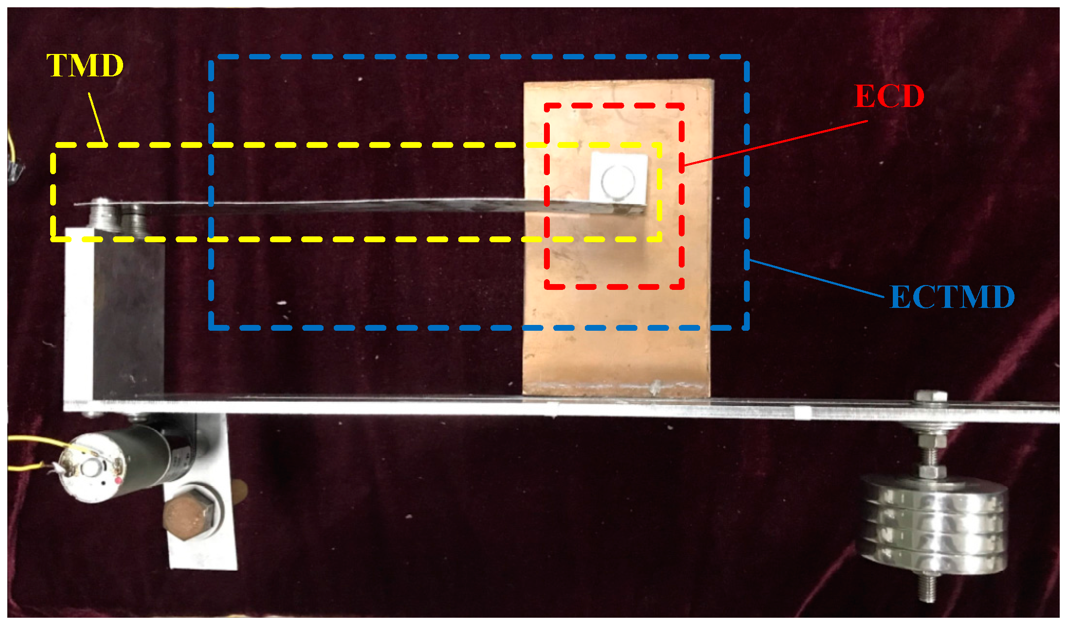
The configuration of the designed ECTMD is shown in Figure 4. The ECTMD consists of a small cantilever beam, a copper plate and a cube of acrylic glass embedded with a disk magnet. One end of the small cantilever beam is fixed on the controlled cantilever beam, and the other end is attached to the cube acrylic glass. The copper plate is fixed on the primary cantilever beam. The gap between the magnet and the copper plate is 3 mm. When the copper plate is removed from the cantilever beam, the ECTMD becomes a TMD. Since the mass of the thin copper plate is relatively small, the fundamental frequency of the cantilever beam will not be affected.
Some parameters of the small cantilever beam, the copper plate and the cylindrical magnet are listed in Table 2, Table 3 and Table 4.
When the fundamental frequency of the cantilever beam is changed from 3.06 Hz to 4.05 Hz, dynamic properties of the ECTMD and TMD, such as the frequency, remain at a constant value, equal to 3.53 Hz.
4. Experimental Results
4.1. Case I: Free Vibration
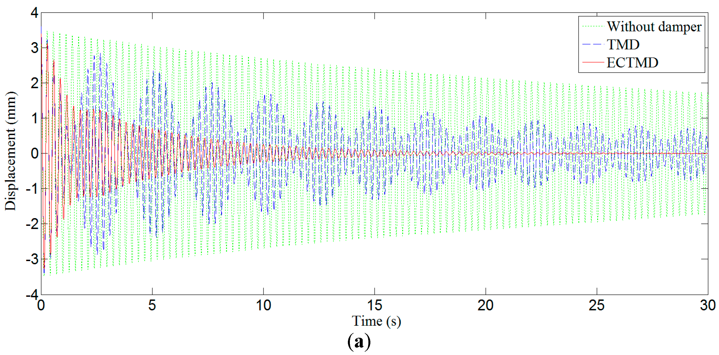
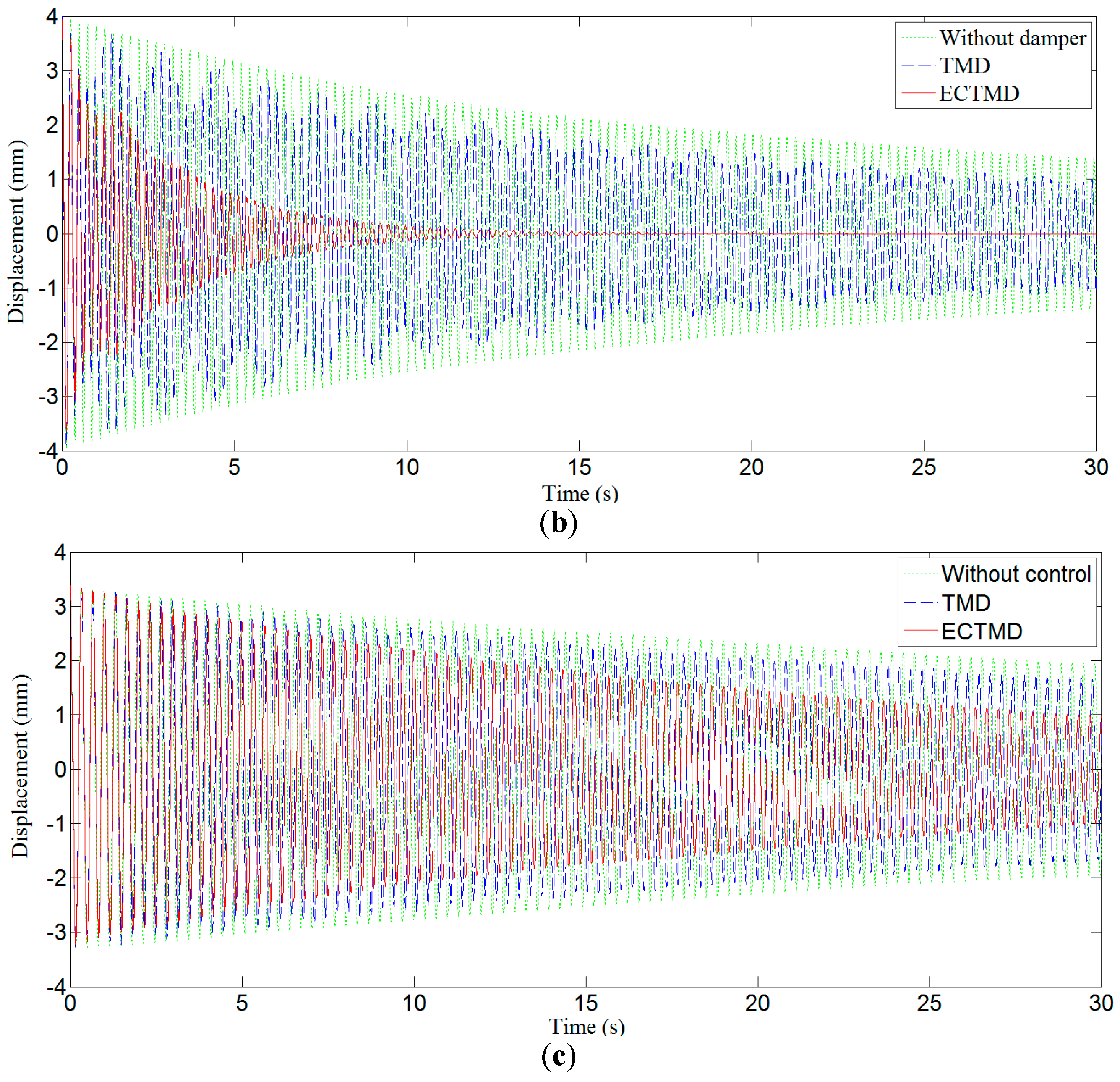
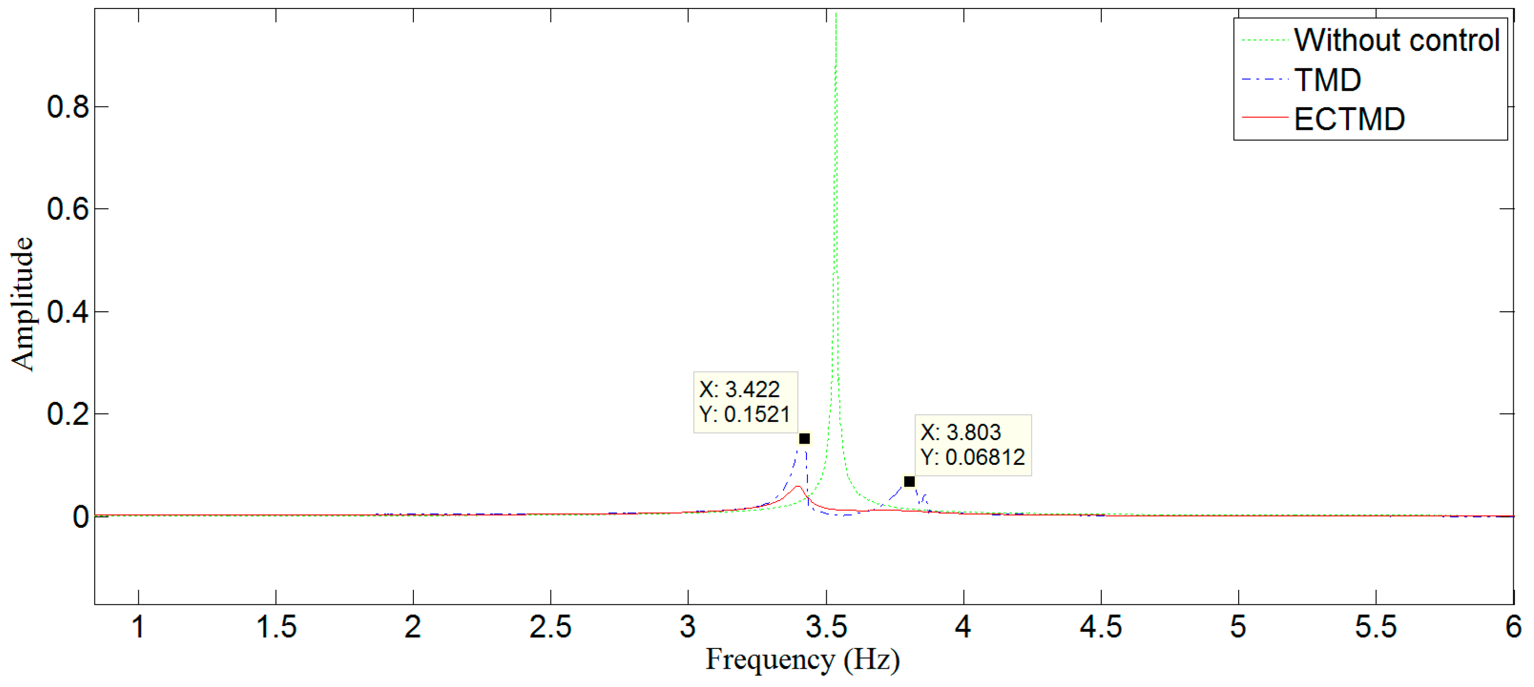
To test the robustness of the ECTMD and the TMD in the free vibration case, an initial displacement is applied to the free end of the primary cantilever beam. The displacement values of the controlled beam are collected for detuned ratios γ of 0%, 14.7% and −13.3%. The free vibration displacements of the controlled structure in these three detuned situations are shown in Figure 5, and the frequency spectra of the free vibration displacements of the controlled structure in the tuned situation are plotted in Figure 6.
As shown in Figure 6, there are two dominant frequencies when the controlled structure is with the TMD, and the difference between these two dominant frequencies is only 0.38 Hz, which indicates that a beat vibration [46] is excited in the structure and the vibration energy of the controlled structure is exchanged between the TMD and the controlled structure. Moreover, the beat vibration and vibration energy transformation can also be seen in Figure 5a,b. We noted that there is no beat vibration when the structure is controlled by the ECTMD.
Figure 5a shows that for the situation with a detuned ratio γ = 0%, the damping ratios of the cantilever beam are 0.14% without control, 0.53% with the TMD and 1.39% with the ECTMD. Figure 5b shows that for the situation with a detuned ratio γ = 14.7%, the damping ratios of the cantilever beam are 0.18% without control, 0.22% with the TMD and 1.3% with the ECTMD. Figure 5c shows that for the situation with a detuned ratio γ = −13.3%, the damping ratios of the cantilever beam are 0.11% without control, 0.13% with the TMD and 0.27% with the ECTMD. The damping ratios of the cantilever beam in various cases are summarized in Table 5.
Both Figure 5 and Table 5 demonstrate that the TMD only works well in the perfectly tuned situation (γ = 0) while the ECTMD still has considerable effectiveness in both tuned and detuned situations (γ = 0, γ = 14.7% and γ = −13.3%), with the equivalent damping ratio of the cantilever beam with the ECTMD being around 2.08~5.91 times that of the TMD control. In addition, it can be seen that the ECTMD works better in the upward-detuned situation (γ = 14.7%) than in the downward-detuned situation (γ = −13.3%). Therefore, from the results in Figure 5, it can be seen that the robustness of the ECTMD is better than that of the TMD in the free vibration case.
4.2. Case II: Forced Vibration
To study the robustness of the ECTMD in the forced vibration case, a motor with an unbalanced mass is used to generate the harmonic excitation on the free end of the cantilever beam. The frequency of the excitation load can be varied from 0 Hz to 5 Hz.
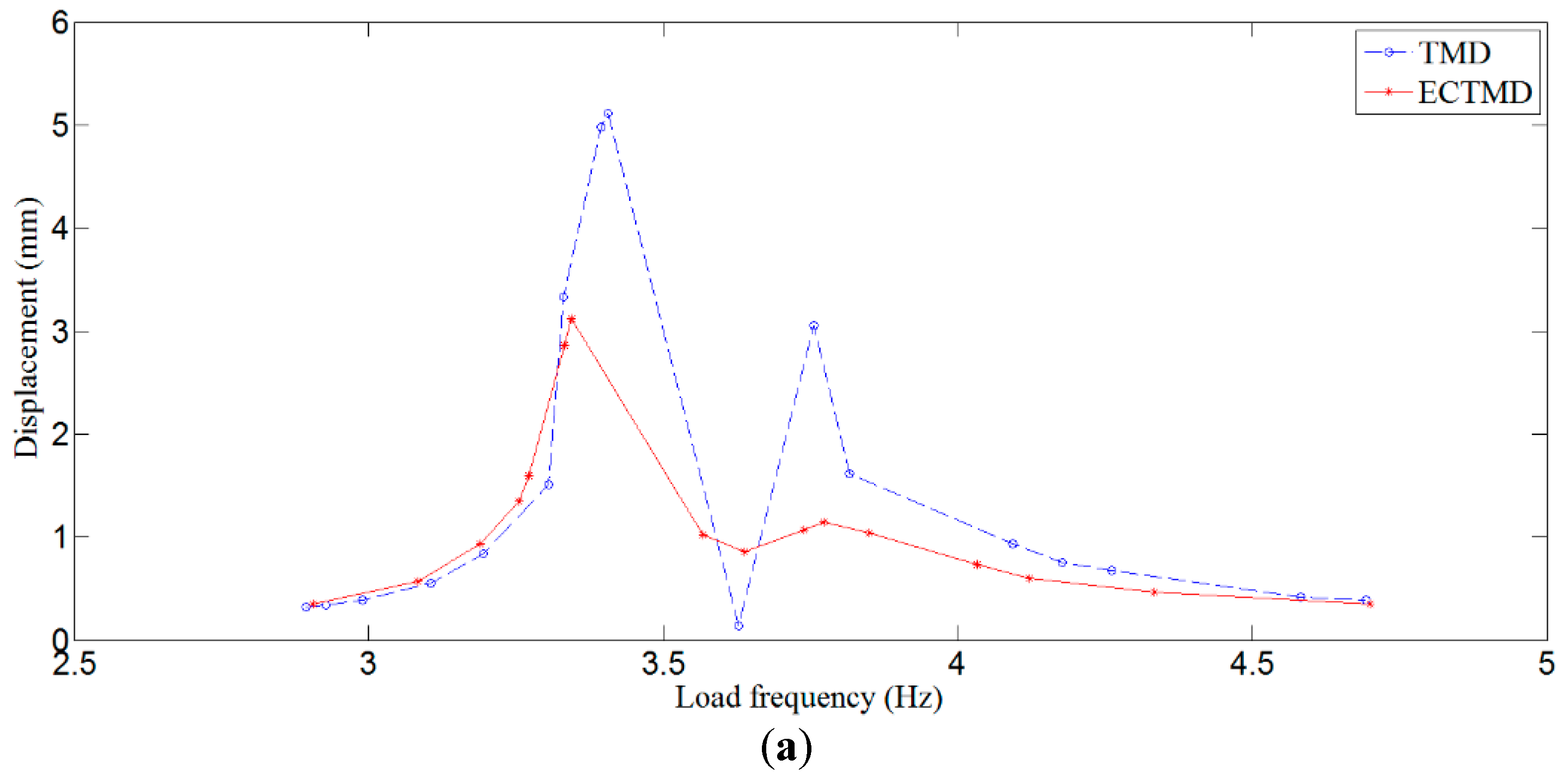
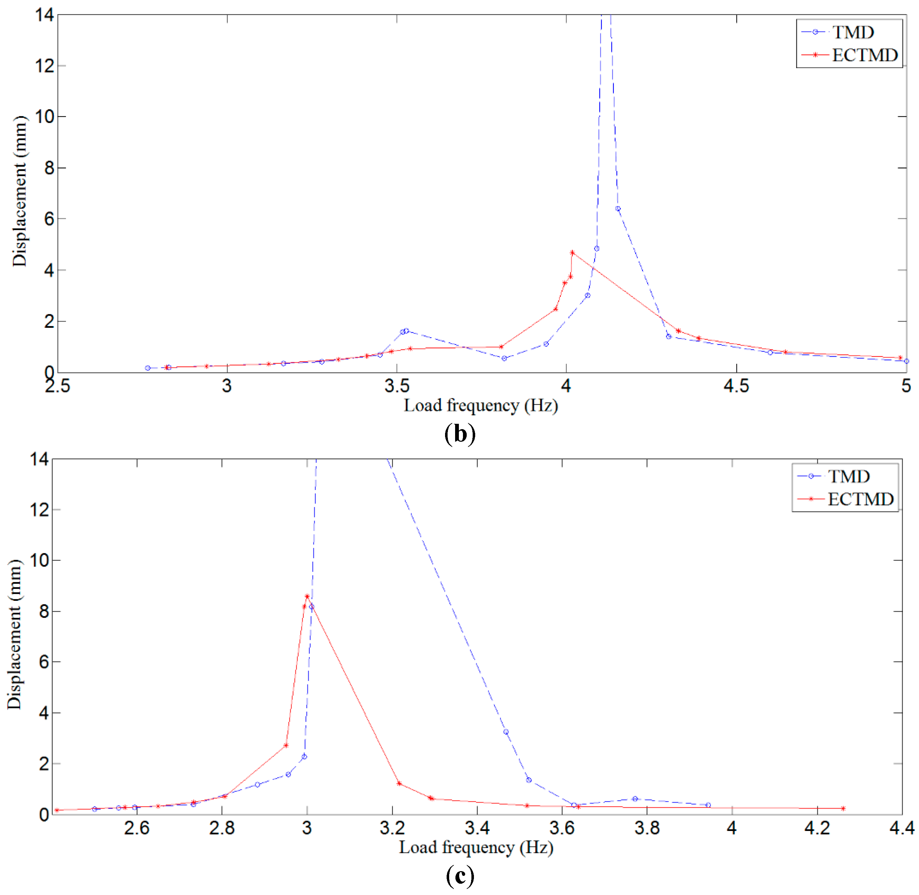
Figure 7 plots the steady-state response of the cantilever beam in a wide frequency domain under different detuned situation. The results show that, when the frequency of the excitation load is larger or smaller than that of the cantilever beam, some new resonance peaks are excited in both tuned and detuned situations (γ = 0%, γ = 14.7% and γ = −13.3%), and the displacement responses of the cantilever beam with the TMD near the resonance peaks are 1.63~2.99 times that with the ECTMD in both tuned and detuned (γ = 0, γ = 14.7% and γ = −13.3%) situations. Therefore, the vibration performances plotted in Figure 7 demonstrate that the robustness of the ECTMD is much better than the TMD in the forced vibration case.
Please note that in Figure 7c the curve (blue dashed line) for the vibration of the primary structure with TMD control is not continuous. The missing segment corresponds to the worst-case vibration of the primary stricture in the case of the TMD control, and was not recorded since the vibration of the primary structure was so severe that the primary structure starts to impact the mass of the TMD.
4.3. Discussion
The experimental results in the free vibration case clearly reveal that a beat vibration is excited in the structure with the TMD, and the TMD reduces the vibration of the controlled structure by transferring the energy to the TMD, and therefore the vibration reduction is effective only in the tuned situation. However, the ECTMD dissipates the vibration energy of the controlled structure by the damping force provided by the ECD and the damping force mainly depends on the relative motion between the damper and the main structure. Therefore, if there is a relative movement, the vibration energy of the controlled structure can be effectively dissipated by the ECTMD in both tuned and de-tuned situations, which results in the strong robustness of the ECTMD.
5. Conclusions
In this paper, the robustness of an ECTMD to control a cantilever beam is studied experimentally under different detuned cases. Moreover, to compare with the performance of the ECTMD, the robustness of a TMD is also studied. The experimental results show that the ECTMD is more robust in both the free vibration case and the forced vibration case. In addition, in the forced vibration case, some new resonance peaks are excited in both perfectly tuned and detuned situations, and the displacement responses of the cantilever beam with the ECTMD near the resonance peaks are much smaller than those with the TMD control in both the downward-detuned and upward-detuned cases. Though we have experimentally demonstrated the robustness of ECTMD in both free vibration and forced vibration cases, an in-depth theoretical analysis of the robustness of the ECTMD is yet to be undertaken, and will be carried out as a future work.
Acknowledgments
The authors are grateful for the financial support from National Natural Science Foundation of China (Grant No.: 51375354 and 51475339).
Author Contributions
All authors discussed and agreed upon the idea, and made scientific contributions. Gangbing Song and Yourong Li designed the experiments and wrote the paper, Junda Chen and Guangtao Lu collected and analyzed the experimental data, Tao Wang and Wenxi Wang designed the ECTMD and revised the paper.
Conflicts of Interest
The authors declare no conflict of interest.
References
- Sahasrabudhe, S.S.; Nagarajaiah, S. Semi-active control of sliding isolated bridges using MR dampers: An experimental and numerical study. Earthq. Eng. Struct. Dyn. 2005, 34, 965–983. [Google Scholar] [CrossRef]
- Ou, J.; Zhang, W. Analysis and design method for wind-induced vibration passive damping control of tall buildings. J. Build. Struct. 2003, 6, 4. [Google Scholar]
- Basu, B.; Bursi, O.S.; Casciati, F.; Casciati, S.; Del Grosso, A.E.; Domaneschi, M.; Faravelli, L.; Holnicki-Szulc, J.; Irschik, H.; Krommer, M. A european association for the control of structures joint perspective. Recent studies in civil structural control across europe. Struct. Control Health Monit. 2014, 21, 1414–1436. [Google Scholar] [CrossRef]
- Li, L.; Song, G.; Ou, J. Hybrid active mass damper (AMD) vibration suppression of nonlinear high-rise structure using fuzzy logic control algorithm under earthquake excitations. Struct. Control Health Monit. 2011, 18, 698–709. [Google Scholar] [CrossRef]
- Spencer, B., Jr.; Nagarajaiah, S. State of the art of structural control. J. Struct. Eng. 2003, 129, 845–856. [Google Scholar] [CrossRef]
- Casciati, F.; De Stefano, A.; Matta, E. Simulating a conical tuned liquid damper. Simul. Model. Pract. Theory 2003, 11, 353–370. [Google Scholar] [CrossRef]
- Casciati, F.; Faravelli, L. A passive control device with sma components: From the prototype to the model. Struct. Control Health Monit. 2009, 16, 751–765. [Google Scholar] [CrossRef]
- Casciati, F.; Rodellar, J.; Yildirim, U. Active and semi-active control of structures–theory and applications: A review of recent advances. JIMSS 2012, 23, 1181–1195. [Google Scholar] [CrossRef]
- Nagarajaiah, S.; Sonmez, E. Structures with semiactive variable stiffness single/multiple tuned mass dampers. J. Struct. Eng. 2007, 133, 67–77. [Google Scholar] [CrossRef]
- Casciati, F.; Domaneschi, M. Semi-active electro-inductive devices: Characterization and modelling. JVC 2007, 13, 815–838. [Google Scholar] [CrossRef]
- Casciati, S.; Faravelli, L.; Chen, Z. A DC-motor based active-mass-damper with wireless feedback for structural control. In Proceedings of the International Symposium on Innovation & Sustainability of Structures in Civil Engineering, Xiamen, China, 28–30 October 2011; Southeast University Press: Xiamen, China, 2011; pp. 560–565. [Google Scholar]
- Casciati, S.; Chen, Z. An active mass damper system for structural control using real-time wireless sensors. Struct. Control Health Monit. 2012, 19, 758–767. [Google Scholar] [CrossRef]
- Li, L.; Song, G.; Ou, J. Adaptive fuzzy sliding mode based active vibration control of a smart beam with mass uncertainty. Struct. Control Health Monit. 2011, 18, 40–52. [Google Scholar] [CrossRef]
- Yang, G.; Spencer, B.F., Jr.; Jung, H.-J.; Carlson, J.D. Dynamic modeling of large-scale magnetorheological damper systems for civil engineering applications. J. Eng. Mech. 2004, 130, 1107–1114. [Google Scholar] [CrossRef]
- Lu, G.; Li, Y.; Song, G. Analysis of a magneto-rheological coupler with misalignment. Smart Mater. Struct. 2011, 20, 105028. [Google Scholar] [CrossRef]
- Zhengqiang, Y.; Aiqun, L.; Youlin, X. Fluid viscous damper technology and its engineering application for structural vibration energy dissipation. J. Southeast Univ. 2002, 32, 466–473. [Google Scholar]
- Isalgue, A.; Lovey, F.C.; Terriault, P.; Martorell, F.; Torra, R.M.; Torra, V. SMA for dampers in civil engineering. Mater. Trans. 2006, 47, 682–690. [Google Scholar] [CrossRef]
- Demetriou, D.; Nikitas, N. A novel hybrid semi-active mass damper configuration for structural applications. Appl. Sci. 2016, 6, 397. [Google Scholar] [CrossRef]
- Zhang, Z.; Ou, J.; Li, D.; Zhang, S. Optimization design of coupling beam metal damper in shear wall structures. Appl. Sci. 2017, 7, 137. [Google Scholar] [CrossRef]
- Li, H.; Qian, H.; Song, G.; Gao, D. Type of shape memory alloy damper: Design, experiment and numerical simulation. J. Vib. Eng. 2008, 21, 179–184. [Google Scholar]
- Song, G.; Zhang, P.; Li, L.; Singla, M.; Patil, D.; Li, H.; Mo, Y. Vibration control of a pipeline structure using pounding tuned mass damper. J. Eng. Mech. 2016, 142, 04016031. [Google Scholar] [CrossRef]
- Lin, W.; Song, G.; Chen, S. PTMD control on a benchmark TV tower under earthquake and wind load excitations. Appl. Sci. 2017, 7, 425. [Google Scholar] [CrossRef]
- Zhao, D.; Li, H.; Song, G.; Qian, H. Experiment investigation for a new type of piezoelectric friction damper. In Proceedings of the Earth and Space 2014, St. Louis, MO, USA, 27–29 October 2014; ASCE: Reston, VA, USA, 2014; pp. 642–647. [Google Scholar]
- Yang, G.; Spencer, B.; Carlson, J.; Sain, M. Large-scale mr fluid dampers: Modeling and dynamic performance considerations. Eng. Struct. 2002, 24, 309–323. [Google Scholar] [CrossRef]
- Cao, H.; Reinhorn, A.; Soong, T. Design of an active mass damper for a tall tv tower in Nanjing, China. Eng. Struct. 1998, 20, 134–143. [Google Scholar] [CrossRef]
- Casciati, F.; Ubertini, F. Nonlinear vibration of shallow cables with semiactive tuned mass damper. Nonlinear Dyn. 2008, 53, 89–106. [Google Scholar] [CrossRef]
- Rana, R.; Soong, T. Parametric study and simplified design of tuned mass dampers. Eng. Struct. 1998, 20, 193–204. [Google Scholar] [CrossRef]
- Lin, Y.-Y.; Cheng, C.-M.; Lee, C.-H. A tuned mass damper for suppressing the coupled flexural and torsional buffeting response of long-span bridges. Eng. Struct. 2000, 22, 1195–1204. [Google Scholar] [CrossRef]
- Tubino, F.; Piccardo, G. Tuned mass damper optimization for the mitigation of human-induced vibrations of pedestrian bridges. Meccanica 2015, 50, 809–824. [Google Scholar] [CrossRef]
- Abdel-Rohman, M.; John, M.J. Control of wind-induced nonlinear oscillations in suspension bridges using a semi-active tuned mass damper. J. Vib. Control 2006, 12, 1049–1080. [Google Scholar] [CrossRef]
- Lin, C.; Wang, J.-F.; Chen, B. Train-induced vibration control of high-speed railway bridges equipped with multiple tuned mass dampers. J. Bridge Eng. 2005, 10, 398–414. [Google Scholar] [CrossRef]
- Jo, B.-W.; Tae, G.-H.; Lee, D.-W. Structural vibration of tuned mass damper-installed three-span steel box bridge. Int. J. Press. Vessels. Pip. 2001, 78, 667–675. [Google Scholar] [CrossRef]
- Kawaguchi, A.; Teramura, A.; Omote, Y. Time history response of a tall building with a tuned mass damper under wind force. J. Wind Eng. Ind. Aerodyn. 1992, 43, 1949–1960. [Google Scholar] [CrossRef]
- Kang, J.; Kim, H.S.; Lee, D.G. Mitigation of wind response of a tall building using semi-active tuned mass dampers. Struct. Des. Tall Spec. Build. 2011, 20, 552–565. [Google Scholar] [CrossRef]
- Youssef, N. Supertall buildings with tuned mass damper. Struct. Des. Tall Spec. Build. 1994, 3, 1–12. [Google Scholar] [CrossRef]
- Ebrahimi, B.; Khamesee, M.B.; Golnaraghi, F. A novel eddy current damper: Theory and experiment. J. Phys. D Appl. Phys. 2009, 42, 075001. [Google Scholar] [CrossRef]
- Sodano, H.A.; Bae, J.-S.; Inman, D.J.; Belvin, W.K. Concept and model of eddy current damper for vibration suppression of a beam. J. Sound Vib. 2005, 288, 1177–1196. [Google Scholar] [CrossRef]
- Van Beek, T.; Pluk, K.; Jansen, J.; Lomonova, E. Optimization and measurement of eddy current damping applied in a tuned mass damper. In Proceedings of the 2014 International Conference on Electrical Machines (ICEM), Berlin, Germany, 2–5 September 2014; IEEE: New York, NY, USA; pp. 609–615. [Google Scholar]
- Bae, J.-S.; Kwak, M.K.; Inman, D.J. Vibration suppression of a cantilever beam using eddy current damper. J. Sound Vib. 2005, 284, 805–824. [Google Scholar] [CrossRef]
- Zhang, H.; Kou, B.; Jin, Y.; Zhang, L.; Zhang, H.; Li, L. Modeling and analysis of a novel planar eddy current damper. J. Appl. Phys. 2014, 115, 17E709. [Google Scholar] [CrossRef]
- Bae, J.-S.; Hwang, J.-H.; Kwag, D.-G.; Park, J.; Inman, D.J. Vibration suppression of a large beam structure using tuned mass damper and eddy current damping. Shock Vib. 2014, 2014, 893914. [Google Scholar] [CrossRef]
- Ao, W.K.; Reynolds, P. Analytical and experimental study of eddy current damper for vibration suppression in a footbridge structure. In Dynamics of Civil Structures; Conference Proceedings of the Society for Experimental Mechanics Series; Springer: New York, NY, USA, 2017; pp. 131–138. [Google Scholar]
- Niu, H.; Chen, Z.; Lei, X.; Hua, X. Development of eddy current turned mass damper for suppressing windinduced vibration of bridge hangers. In Proceedings of the 6th European and African Wind Engineering Conference, Cambridge, UK, 7–11 July 2013. [Google Scholar]
- Lu, X.; Zhang, Q.; Weng, D.; Zhou, Z.; Wang, S.; Mahin, S.A.; Ding, S.; Qian, F. Improving performance of a super tall building using a new eddy-current tuned mass damper. Struct. Control Health Monit. 2017, 24, e1882. [Google Scholar] [CrossRef]
- Li, H.; Zhang, P.; Song, G.; Patil, D.; Mo, Y. Robustness study of the pounding tuned mass damper for vibration control of subsea jumpers. Smart Mater. Struct. 2015, 24, 095001. [Google Scholar] [CrossRef]
- Thomson, W.T.; Dahleh, M.D. Theory of Vibration with Applications, 5th ed.; Prentice Hall: Upper Saddle River, NJ, USA, 1998; pp. 131–135. ISBN 013651068X. [Google Scholar]
Figure 1.
A cantilever beam controlled by an eddy current tuned mass damper (ECTMD).

Figure 2.
Experimental setup for robustness study.

Figure 3.
A moveable lumped weight installed on the cantilever beam.
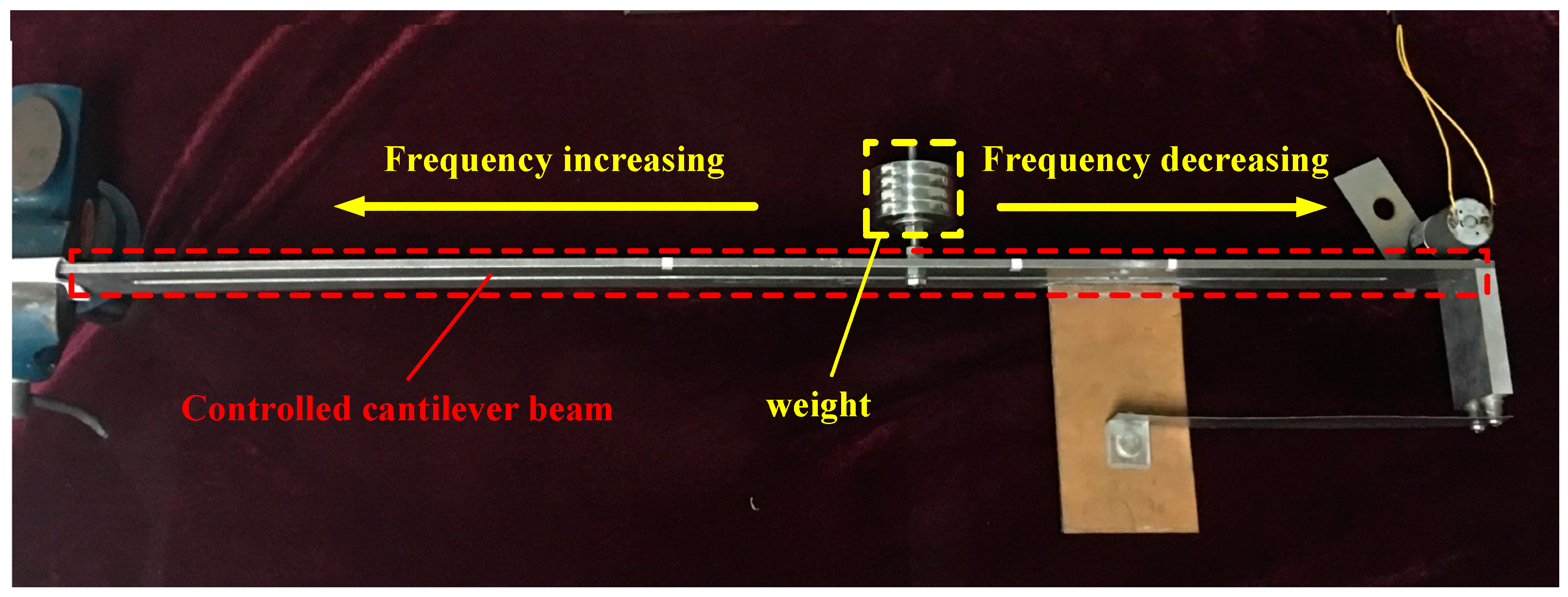
Figure 4.
The configuration of the ECTMD.

Figure 5.
Free vibration responses of the cantilever beam in different situations. (a) Detuned ratio 0%; (b) Detuned ratio 14.7%; (c) Detuned ratio −13.3%.
Figure 5.
Free vibration responses of the cantilever beam in different situations. (a) Detuned ratio 0%; (b) Detuned ratio 14.7%; (c) Detuned ratio −13.3%.


Figure 6.
Frequency spectrum of the free vibration response of the cantilever beam in tuned situations.
Figure 6.
Frequency spectrum of the free vibration response of the cantilever beam in tuned situations.

Figure 7.
Frequency responses of the cantilever beam in different detuned situations. (a) Detuned ratio 0%; (b) Detuned ratio 14.7%; (c) Detuned ratio −13.3%.
Figure 7.
Frequency responses of the cantilever beam in different detuned situations. (a) Detuned ratio 0%; (b) Detuned ratio 14.7%; (c) Detuned ratio −13.3%.


Table 1.
Parameters of the primary cantilever beam.
| Parameter | Value |
|---|---|
| Material | Stainless steel 304 |
| Length | 750 mm |
| Width | 40 mm |
| Thickness | 5 mm |
| Adjustable frequency range | 3.06 Hz~4.05 Hz |
Table 2.
Parameters of the small cantilever beam.
| Parameter | Value |
|---|---|
| Material | Stainless steel 304 |
| Length | 180 mm |
| Width | 30 mm |
| Thickness | 0.3 mm |
Table 3.
Parameters of the copper plate.
| Parameter | Value |
|---|---|
| Material | Copper |
| Thickness | 1 mm |
Table 4.
Parameters of the magnet.
| Parameter | Value |
|---|---|
| Material | N35 (NdFeB) |
| Diameter | 12 mm |
| Height | 10 mm |
Table 5.
Equivalent damping ratios in different situations.
| Detuned Ratio | Without Control | With TMD | With ECTMD |
|---|---|---|---|
| γ = 14.7% | 0.18% | 0.22% | 1.3% |
| γ = 0 | 0.14% | 0.53% | 1.39% |
| γ = −13.3% | 0.11% | 0.13% | 0.27% |
© 2017 by the authors. Licensee MDPI, Basel, Switzerland. This article is an open access article distributed under the terms and conditions of the Creative Commons Attribution (CC BY) license (http://creativecommons.org/licenses/by/4.0/).
Share and Cite
MDPI and ACS Style
Chen, J.; Lu, G.; Li, Y.; Wang, T.; Wang, W.; Song, G. Experimental Study on Robustness of an Eddy Current-Tuned Mass Damper. Appl. Sci. 2017, 7, 895. https://doi.org/10.3390/app7090895
AMA Style
Chen J, Lu G, Li Y, Wang T, Wang W, Song G. Experimental Study on Robustness of an Eddy Current-Tuned Mass Damper. Applied Sciences. 2017; 7(9):895. https://doi.org/10.3390/app7090895
Chicago/Turabian StyleChen, Junda, Guangtao Lu, Yourong Li, Tao Wang, Wenxi Wang, and Gangbing Song. 2017. "Experimental Study on Robustness of an Eddy Current-Tuned Mass Damper" Applied Sciences 7, no. 9: 895. https://doi.org/10.3390/app7090895
Note that from the first issue of 2016, this journal uses article numbers instead of page numbers. See further details here.