
A Review of Distributed Fibre Optic Sensors for Geo-Hydrological Applications


National Research Council, Research Institute for Geo-Hydrological Protection, Corso Stati Uniti 4, I-35127 Padova, Italy
Appl. Sci. 2017, 7(9), 896; https://doi.org/10.3390/app7090896
Submission received: 5 August 2017
/
Revised: 25 August 2017
/
Accepted: 27 August 2017
/
Published: 1 September 2017
(This article belongs to the Special Issue Distributed Optical Fiber Sensors)
Abstract
:Featured Application
Distributed fibre optic sensors for geo-hydrological applications: a comprehensive review about methodology, weaknesses, and strengths.
Abstract
Distributed optical fibre sensing, employing either Rayleigh, Raman, or Brillouin scattering, is the only physical-contact sensor technology capable of accurately estimating physical fields with spatial continuity along the fibre. This unique feature and the other features of standard optical fibre sensors (e.g., minimal invasiveness and lightweight, remote powering/interrogating capabilities) have for many years promoted the technology to be a promising candidate for geo-hydrological monitoring. Relentless research efforts are being undertaken to bring the technology to complete maturity through laboratory, physical models, and in-situ tests. The application of distributed optical fibre sensors to geo-hydrological monitoring is here reviewed and discussed, along with basic principles and main acquisition techniques. Among the many existing geo-hydrological processes, the emphasis is placed on those related to soil levees, slopes/landslide, and ground subsidence that constitute a significant percentage of current geohazards.
1. Introduction
The era of optical fibre sensors (OFSs) started 50 years ago with the granting of the Fotonic sensor (U.S.03327584; 27 June 1967) [1], almost together with the advent of fibre-optic communication technology.
The many features offered by OFSs that make this technology surpass conventional ones have been widely addressed by several review papers, and include the immunity to electromagnetic interference, minimal invasiveness and lightweight, multi-parameters sensing, ease of multiplexing, and remote powering/interrogating capabilities. Furthermore, it is the only technology that enables the distributed monitoring of some physical fields (e.g., strain, temperature) along the fibre (i.e., with spatial continuity of the measurands). This particular type of OFS is called a distributed optical fibre sensor (DOFS) and exploits scattering processes occurring in the fibre. The features mentioned above along with this unique ability of DOFSs made them perfect candidates for sensing applications in harsh environments characterised by large geographical extension and requiring a high spatial density of sensing points like geo-hydrological monitoring. Early applications of DOFSs into geo-hydrological monitoring can be dated to more than 25 years ago, first with distributed temperature measurement campaigns in soil levees and embankments, but other examples regarding slope stability and landslide monitoring by distributed strain sensing soon followed.
In the following sections, the application of DOFSs to some critical geo-hydrological processes will be presented and discussed. A great effort has been undertaken to include as many significant papers as possible, but at the same time, we are aware that many others have been published about these topics. Ultimately, the included references have been carefully chosen to support the understanding of key issues and potentials of DOFS technology in this field and with the aim of offering a comprehensive review of the use of DOFSs in practical geo-hydrological applications, both in-situ and in physical models.
Firstly, the fundamental principles at the basis of distributed optical fibre sensing are introduced with a brief review of the acquisition techniques that are currently implemented in DOFSs. In particular, the three different processes employed in DOFSs—namely Raman, Brillouin, and Rayleigh scattering—are addressed separately, discussing their respective weaknesses and strengths.
In the second part of the paper, the application of DOFSs to geo-hydrological monitoring is reviewed and discussed. The review is about the monitoring of levees, slope and subsidence processes causing the main common geomorphic hazards. Other minor applications are not considered in this review. Similarly, the paper includes neither approaches where distributed techniques are used only to interrogate concatenations of single point sensors [2,3] nor transducers inducing losses at discrete points along the fibre (e.g., employing bending) [4,5].
2. Distributed Optical Fibre Sensors
The common assumption that enables the sensing feature in optical fibres is that the surrounding environment affects the local properties of the fibre itself. As mentioned above, at the basis of all the DOFSs, there are the following three scattering processes: Rayleigh, Raman, and Brillouin scattering [6]. Despite the different scattering processes, the sensing mechanism is the same for all of them: the back propagating light generated when an optical signal is fed into the fibre is used to probe the local properties of the fibre, and therefore to figure out the changes in the surrounding environment. Regarding Raman and Brillouin scattering, environmental conditions directly affect the corresponding backscattered signals used as probes. For example, the fibre’s local temperature intrinsically affects the intensity of the anti-Stokes Raman scattered signal, and this dependence has been successfully exploited to implement distributed temperature sensors (DTSs). Similarly, local temperature and strain intrinsically influence frequency and intensity of Brillouin-scattered signal, and Brillouin scattering is used to implement distributed temperature and distributed strain sensors (DSSs).
Conversely, Rayleigh-based distributed sensing is less straightforward: Rayleigh scattering is in fact intrinsically independent of almost any external physical fields that may affect the surrounding environment. Therefore, rather than the scattering process per se, Rayleigh scattering is used to measure environment-dependent propagation effects. Attenuation/gain, as well as phase interference and polarisation rotation, are among the propagation effects that are currently detected to implement Rayleigh-based DOFSs. Of course, Raman and Brillouin scattering can also be used in principle to measure these propagation effects, but direct sensing mechanisms are preferred due to their simplicity and effectiveness.
In the following sections, the principle of distributed sensing for the three scattering processes are briefly overviewed: for an extensive description of working principles and recent research achievements (which are outside the scope of this paper), we direct the reader to some excellent reviews and resources [7,8,9,10,11].
2.1. Rayleigh-Based Distributed Sensing
Rayleigh scattering is an elastic process resulting from local variations of refractive index due to heterogeneity and density fluctuation of the material [12,13]. Because of that heterogeneity, a small portion of the incident light is scattered at specific points called scattering centres. These scattering centres are randomly distributed along the fibre and act as weak reflectors, reflecting the light in all directions. However, only the fraction of the scattered light falling within the angle of acceptance of the fibre in the opposite direction is captured by the guiding structure of the fibre itself, and back-propagates to the input.
The backscattered signal has peculiar properties [14]: first of all, the intensity of incident light backscattered at a scattering centre is attenuated over the round-trip length (i.e., from the fibre input to the centre’s position). Furthermore, on average, each portion of fibre illuminated at any time by a single pulse is expected to radiate the same backscattered intensity broadly. This effect can be easily revealed with a broadband pulsed incident light. However, when a narrowband laser is used, each scattering centre illuminated by the same probe pulse contributes coherently to the backscattered light. Overall, the intensity and phase of the light reflected all along the fibre are determined by the vector sum of all electric fields radiated by the scattering centres, and therefore depend on the amplitude and position of scattering centres along the fibre. Both the amplitude and position are randomly distributed but fixed in time as long as the relative phase difference (i.e., optical distance) among illuminated scattering centres does not change [15]. In the case of broadband sources, these coherent effects still present, determining only a tiny fluctuation around the average scattering intensity.
At the basis of all Rayleigh DOFSs, there is the detection of the counter-propagating signal, and in turn, of the attenuation along the fibre. To this aim, two main approaches can be followed:
- To determine the attenuation in the time domain, with pulse signals (i.e., to determine the roundtrip impulse response of the fibre), known as optical time domain reflectometer (OTDR).
- To characterise the attenuation in the frequency domain, with a frequency-modulated continuous wave signal (i.e., to determine the roundtrip frequency response of the fibre), known as optical frequency domain reflectometer (OFDR).
Notably, the intensity of the backscattered signal in single-mode fibres is rather small (approximately 55 dBs lower than that of the probe light), and this represents one of the main challenges to the implementation of Rayleigh-based DOFSs—either in time or frequency domain.
2.1.1. Optical Time Domain Reflectometry
Historically speaking, OTDR was developed almost simultaneously by two independent research groups: Barnosky and Jensen at Hughes Research Laboratory [16] and Personick at Bell Telephone Laboratories [17]. In particular, Parsonick applied the technique directly to installed links and firstly provided an expression for the received signal levels. The first ever proposed DOFS was indeed based on a polarisation-sensitive OTDR scheme (POTDR) [18,19], while the original setup of Barnesky, Jensen, and Personick was proposed as a distributed sensor only in 1983 by Hartog et al. [20].
Figure 1 shows the working principle of conventional OTDRs. In that implementation, a broadband source is used to generate light pulses; a circulator (or a coupler) separates the forward path from the backward one; a photodetector measures the light intensity; and dedicated electronics drive the devices, process the data, and record the measurements.
In standard OTDR, the best spatial resolution that can be obtained is half the length of the pulse, but in real applications, other factors (e.g., low signal-to-noise ratio, SNR) may impair the performance and make the resolution worse. An overall reduction of SNR is indeed observed for reduced pulse lengths, as less energy is injected in the fibre: overall, in conventional OTDR, the SNR is roughly proportional to the square of the spatial resolution [9]. To circumvent this limit, other time-domain techniques were proposed over the years, exploiting correlation [21,22], pulse coding [23,24], or photon-counting (-OTDR) [25,26,27].
Another time-domain approach uses the coherent nature of Rayleigh backscattering originated by a narrowband light source: as mentioned above, the backscattered signal is the coherent vectorial sum of fields generated at scattering centres and encodes the information about their position. Like in a distributed multi-path interferometer, the received backscattered signal experiences speckle noise known as Rayleigh fading [28,29]. Despite the randomness distribution of centres’ positions and corresponding relative optical phases, the resulting “interference pattern” represents a snapshot of scattering centres’ positions along the fibre. If the fibre is perturbed (e.g., strained or heated/cooled), the relative positions of scattering centres change (i.e., the relative optical phase difference), causing the interference pattern to change. This change can be tracked, and the mechanism is exploited—also commercially—to implement DOFSs for dynamic strain and vibration detection (distributed vibration sensor, DVS or distributed acoustic sensor, DAS) with spatial resolution comparable to that of conventional OTDRs. This time-domain solution is called phase-OTDR (or -OTDR) [30,31,32,33,34].
2.1.2. Optical Frequency Domain Reflectometry
As discussed above, optical frequency domain reflectometry aims at characterising the frequency response of the fibre under roundtrip propagation. Instead of using a pulse signal, the source is modulated either in intensity or frequency.
Optical frequency domain reflectometry comes in two variants:
- Incoherent OFDR or I-OFDR , obtained by modulating the optical intensity with radio frequency (RF) signals;
- Coherent OFDR, obtained by sweeping the optical frequency.
In these two variants, the sensing information is encoded on an RF or an optical carrier, respectively.
The basic setup of an I-OFDR is similar to that of a conventional OTDR (Figure 1), where the pulsed source is replaced by a continuous wave light modulated in amplitude by an RF signal. The RF signal frequency is linearly swept in a given bandwidth to probe the frequency response of the fibre [35,36].
Similar to conventional OTDR, I-OFDR spatial resolution is inversely proportional to the system bandwidth, here corresponding to the bandwidth swept by RF modulation. Nonetheless, owing to the RF modulation, this approach can benefit from electrical heterodyne detection, in general resulting in better performance compared to OTDR [37,38]. Despite that, at the moment there are no commercial implementations of Rayleigh-based I-OFDR, probably due to the outstanding performance achieved by the coherent counterpart.
The basic setup of coherent OFDR is shown in Figure 2. The light from the source—which is optical frequency-modulated—interferes coherently with the light that was emitted a short time before and scattered back from a certain distance along the sensing fibre [39]. If one assumes that the sweep is linear, the frequency difference between these two light signals is proportional to the propagation time delay along the sensing fibre, and therefore, to distance. This means that the instantaneous beat frequency measured at the detector is mapped to a specific position along the fibre.
The spatial resolution is in this case determined by the wavelength scanning range (or, equivalently, by the frequency scanning range, ). It reads , where c, n, , and are the speed of light, the effective refractive index of the fibre, and lower and upper wavelengths of the frequency scan, respectively [40]. At the same time, if the sweep time is slow enough, the electrical bandwidth needed to manage the frequency sweep can be reasonably modest, down to some MHz. Indeed, the expression of maximum beat frequency, , is given by , where L, , , and are the length of the fibre, the frequency sweep duration, the slope of the frequency sweep (Hz/s), and the maximum fibre delay, respectively. This means that a 1 km-long fibre can be sampled with 10 cm of spatial resolution by sweeping the frequency over 1 GHz in 1 ms ( THz/s) and with a maximum beat frequency of 10 MHz. These values show the advantage of coherent OFDR over other time-domain techniques: high spatial resolution is achieved with a wavelength sweep of some tens of nanometres and a relatively small electric bandwidth.
From early OFDR implementations over short fibres more than 30 years ago [41], it took a while to reach longer distances, mainly due to the need for coherent sources capable of very linear frequency sweep [42]. To circumvent the issue of the nonlinearity of the frequency sweep, schemes integrating an additional reference interferometer were proposed [43]. The problem of lack of coherence of the source—which limits the measurement range—was also tackled (e.g., by introducing phase-compensation techniques) [44]. Furthermore, the introduction of balanced photodiodes in polarisation diversity scheme determined a further improvement of the sensitivity of heterodyne detection. The resolution of some centimetres over tens of kilometres [45], or millimetres over a few kilometres [46] are now possible—at least in laboratory setups. Moreover, very recently, a commercial polarisation-sensitive OFDR (POFDR) appeared in the market, mainly for birefringence measurements and devices characterisation.
To conclude this section, we report the performance of some commercial Rayleigh-based interrogators (Table 1). Please note that the table includes only devices that manufacturers specifically intended for sensing applications.
2.2. Raman-Based Distributed Sensing
Spontaneous Raman scattering is an inelastic process caused by molecular vibrations. The incident light interacting with the electrons of vibrating molecules (optical phonons) is scattered, and its frequency is shifted by an amount equivalent to the resonance frequency of the lattice oscillation [48]. Optical fibres made from doped SiO quartz glass show an amorphous solid structure that undergoes molecular oscillations: the molecular bonds in glasses are not uniform and corresponding vibrational modes slightly differ along the fibre. Therefore, Raman scattering of quartz glass is the result of one or more aggregated bands corresponding to the main vibration modes of the molecules.
When light is launched into a fibre to probe the Raman scattering, three spectral components are generated: the Rayleigh scattered signal at the wavelength of input light, the Stokes component at a higher wavelength, and the anti-Stokes component at a lower wavelength. Corresponding frequency shifts are approximately 13 THz for silica glass fibre, and due to the aforementioned molecular bonds’ inhomogeneity, the bandwidth is very wide (up to approx. 6 THz). The intensity of the anti-Stokes signal is temperature-dependent (sensitivity of approx. K at room temperature), while the Stokes signal is temperature insensitive. Therefore, the ratio between the anti-Stokes and the Stokes light intensity is a direct measurement of the temperature at which backscattered photons have been generated [49,50]. It is worth mentioning that Raman scattering is a nonlinear process, but the reader should not be confused about this: in all DOFSs based on Raman scattering, the relationship between the scattered power and the input power of the probe is linear.
The first proposal of Raman-based DOFSs can be dated to the first years of the 1980s [49,51,52]. Raman distributed temperature sensor (DTS) systems are mostly based on Raman optical time domain reflectometry implemented with a pulse laser and analogue receivers. Its working principle is relatively simple, and consists of sending a pulse in the fibre to measure Stokes and anti-Stokes band responses over roundtrip propagation. The corresponding implementation scheme (Figure 3) is simple as well: it includes a laser light source, a directional coupler to separate the forward signal to the backward one and to separate the Stokes from the anti-Stokes band. Photodetectors and devoted electronics to control the devices and to process and store recorded data complete the setup. Between the coupler and the sensing fibre is often inserted a section of fibre at a known temperature, used for reference and system calibration.
In Raman-DTS exploiting the ratio of the anti-Stokes signal to the Stokes one, the directional coupler consists of a large bandwidth wavelength division multiplexer or a dichroic coupler, capable of routing the backscattered Stokes and anti-Stokes bands onto separate detectors. Please note that Rayleigh scattering is the strongest among the three different kinds of scattered light, followed by Brillouin scattering (15–20 dB weaker), and Raman is the weakest at 10 dB weaker than Brillouin. Therefore, Raman-DTSs require many backscattered pulses to be collected and averaged to reach an adequate SNR level. Other implementations are also possible; for example, a less-demanding hardware setup replaces the coupler with a simple circulator or coupler, with only one receiver channel equipped with an optical filter. This filter is mechanically switched to separate the anti-Stokes from the Stokes component, and the light is directed to a single photodetector.
In principle, Raman scattering is generated at any wavelength of the input probe light. Nonetheless, the kind of fibre that is used poses some practical limitations: in case of multimode fibres (currently the most common choice in Raman-DTSs), the main limitation is due to the intermodal dispersion that broadens the impulse, degrading the spatial resolution. Instead, single mode fibres require the anti-Stokes signal to be at a wavelength longer than the fibre cut-off wavelength (i.e., the wavelength below which the second transverse mode propagates) that for standard single mode fibres is usually around 1300 nm. Other considerations deal with the power available at the anti-Stokes photodetector and with the availability of high-power sources and detectors at the operative wavelengths. Overall, practical implementations of Raman-DTSs are conveniently distinguished according to the working range. In this regard, short-range Raman-DTSs, operating with multimode fibres, laser sources at 850–910 nm, and standard silicon avalanche photodetectors, are limited to a distance range up to 5 km, mainly due to the low emitted power and poor launching efficiency. Medium-range systems, operating with multimode fibres, high-performance laser sources at 1064 nm, and silicon photodetectors, cover distances up to 15 km, limited by nonlinear optical effects. Ultimately, long-range systems, operating at 1550 nm, employ mainly single mode fibres over distances larger than 15 km; in this case, the detection requires devices operating at long wavelengths, such as InGaAs photodetectors.
It is worth mentioning that improved and alternative designs have been proposed over the years, including commercially—e.g., photon-counting Raman OTDRs [53,54,55,56,57], pulse compression/coding schemes [58,59,60,61], or incoherent Raman OFDRs, in respect of which we direct the reader to the corresponding references. Remarkably, in [62], a resolution of 0.09 °C in a 1100 m-long fibre with 0.39 m spatial sampling was achieved with direct detection approach.
To conclude this section, we report in Table 2 the performance achieved by some commercial interrogators. Please note that the reported values of resolution are obtained only after proper calibration. In fact, the calibration addresses two fundamental issues of Raman-DTSs: the differential attenuation between anti-Stokes and Stokes Raman signals that significantly impairs system performance and the normalisation of the signals from the sensing fibre [63]. The most simple approach proposed by most of the commercial Raman-DTSs consists of introducing a correction factor calculated from the measurement of temperature at the beginning of the fibre and at its remote end (if accessible) using other temperature sensors (see Figure 4a). This is the common approach used for single-ended deployment (i.e., with the fibre extending from the interrogator, with only one connection to the instrument). Other calibration approaches requiring different fibre layouts (e.g., duplexed single-ended and double-ended configuration; see Figure 4) can be implemented for better accuracy and robustness [64].
2.3. Brillouin-Based Distributed Sensing
Spontaneous Brillouin scattering is another inelastic process occurring in optical fibres. The interaction between the incident light wave and the thermally-induced material-density fluctuations (acoustic phonons) travelling along the fibre at the speed of sound is the phenomenon that underlies the scattering process. Due to the stress-optical effect, a modulation of the refractive index propagates along the fibre at the same speed [12]. In this interaction, the wavelength matching among longitudinal acoustic phonons and input probe optical wavelength generates two additional signals at wavelengths on either side of the probe, as occurs for Raman scattering [65]. Frequency shift and intensity of the generated signals are sensitive to both strain and temperature, and this dependence is exploited in Brillouin-based DOFS, whose early proposals are dated at the end of the 1980s [66,67,68].
To the aim of DOFSs implementation, spontaneous Brillouin scattering is similar to spontaneous Raman scattering. The most simple approach for detecting spontaneous Brillouin scattering is in fact the same as for Raman-based OTDR, and the term Brillouin optical time-domain reflectometer (BOTDR) refers properly to the time domain interrogation of back-propagating spontaneous Brillouin scattering. With respect to Raman, the bands generated are very narrow (approx. 30 MHz vs. 6 THz for Raman scattering) and the frequency shift is small (approx. 10 GHz vs. 13 THz). Finally, as mentioned above, the intensity of backscatter signal is substantially stronger in spontaneous Brillouin than Raman, although less sensitive to temperature, making the detection less critical. Typical sensitivity coefficients of Brillouin frequency shift vs. strain and temperature in step index single-mode fibres are 0.046 MHz/ and 1.07 MHz/°C, respectively. Regarding the intensity, we have instead and °C, correspondingly [69,70].
Over the years, all these features promoted Brillouin scattering as the most widespread and studied distributed sensing platform in many practical applications. In fact, the very narrow bandwidth of Brillouin scattering drove the implementation of heterodyne techniques with high SNR over long distance [70,71], also supported by the viability of optical amplification [72,73] and optical pulse coding [74,75]. Furthermore, specific implementations of Brillouin-based DOFSs allow the discrimination of temperature from strain, either by measuring the spontaneous Brillouin intensity and Brillouin frequency shift simultaneously [70,76] or by measuring multi-peak Brillouin spectrum in dispersion-shifted fibres [77]. Nonetheless, to our knowledge, only one of the commercial interrogators existing at the moment has implemented this option by exploiting the first of the two techniques mentioned above. Ultimately, a range of several tens of kilometres with spatial resolution on the order of 1 m is attainable with BOTDR schemes. A typical BOTDR setup with a coherent detection stage is represented in Figure 5.
Towards the aim of distributed sensing, another Brillouin scattering process can be exploited; namely, the stimulated Brillouin scattering (SBS) [79]. When two counter-propagating waves separated by the Brillouin frequency are launched at the two ends of the fibre, they interact with each other, resulting in a stimulation of the scattering process. The light at the lower frequency is then amplified due to the energy transfer from the higher frequency wave.
A pump pulse light and a continuous wave probe, injected at the two ends of the fibre, are required to generate stimulated Brillouin scattering. The resulting amplification of the probe light—detected at the input of the fibre—is again temperature and strain dependent. The target of detection for this type of Brillouin-based DOFSs is the time evolution of the gain resulting from the interaction of the two counterpropagating signals, and the technique is called Brillouin optical time domain analysis (BOTDA) [68,80]. A basic BOTDA setup is represented in Figure 6. It is worth noting that all of the commercial implementations of Brillouin-based DOFSs are either BOTDR- or BOTDA-based schemes. In particular, the BOTDR-based one—requiring the access from only one end of the fibre—is the only viable solution in many applications where single-ended deployment is the only possible choice. On the contrary, when both ends of the fibre are accessible, the BOTDA-based technique generally shows better performance.
A very interesting feature of the BOTDA scheme is that it can measure a very large number of sensing points over long distances. Indeed, with proper implementation, it can work over a distance of 100 km or beyond; e.g., by employing Raman amplification [81,82,83] or pulse coding techniques [74,84,85,86,87,88]. Intrinsic spatial resolution over that range is limited to approximately 1 m, due to the reduced acoustic wave response time [89]. Correspondingly, several tens of thousands of sensing points can be measured by the BOTDA schemes. Many optical techniques were also introduced over the years to ameliorate the spatial resolution [90,91,92,93,94]. To our knowledge, a spatial resolution of a few millimetres [94,95] over a range of a few kilometres represents one of the best results achieved so far.
To further increase the number of sensing points over a longer range, other techniques based on stimulated Brillouin scattering were proposed over the years; e.g., Brillouin optical coherence domain reflectometry and Brillouin optical coherence domain analysis, dynamic Bragg gratings, and Brillouin optical frequency domain analysis. The most promising technique at the moment is represented by Brillouin optical correlation domain analysis, which enables measurements over a range of 10 km and beyond, with resolution better than 1 cm (i.e., with more than 1 million sensing points) [96,97].
As in previous sections, we report the specifications of some commercial interrogators in Table 3.
3. Distributed Optical Fibre Sensing Applied to Geo-Hydrological Applications
The realm of geo-hydrological applications is very wide. In this review, we focus on those applications that deal with the so-called geomorphic processes. Substantially, they are natural processes originated at or near the Earth’s surface which include but are not limited to: expansive soils, soil erosion, slope failures, ground subsidence, river channel changes, glaciers, and coastal erosion [98]. They can have human-induced or natural causes, and at the same time, they can determine casualties and huge economic losses: when geomorphic processes threaten human populations they are properly called geomorphic hazards. The relation is unfortunately bi-directional: as the population grows, more people are likely to be exposed to the effects of hazardous geomorphic processes. At the same time, the population growth often accentuates the instability of geomorphic processes at the origin of the hazards.
Great attention is paid among the general public to such natural hazards that represent abrupt changes, such as earthquakes and volcanic eruptions. Nonetheless, larger economic losses and casualties are caused by relatively slow progressive geomorphic hazards like landslides, soil erosions, subsidence, and levee collapses, whose effects may be mitigated by proper monitoring.
In light of that, in the following sections we will present and discuss the applications of DOFS to the three most common geomorphic processes: soil erosion in levees and embankments, slope failures and landslides, and ground subsidence.
3.1. Soil Levees and Embankments Monitoring
Monitoring of soil levees and embankments is aimed at preventing the collapse of the structure. The main hazard is related to occasional or exceptional changes in the watercourses stage level due to intense rainfalls. Many mechanisms can contribute to the collapse of the retaining structure, often involving either the upstream or downstream slope of the embankment as well as its foundation layer. However, one of the major driving phenomena that may lead to the collapse of the structure is the seepage regime variation inside the foundation soil and in the embankment body. Extended periods of high water levels can gradually saturate the levee, thus reducing the soil strength. On the contrary, sudden water level decrease may originate dangerous seepage forces at the upstream slope (i.e., at riverside). Heterogeneities in the foundation soil and discontinuities across the embankment section can contribute to worsening the scenario. Non-uniform hydraulic properties can indeed lead to preferential paths for water infiltration and seepages. Flow localisation contributes to the development of high seepage forces and high flow velocities, and ultimately to the loss of resistance or the formation of pipes inside the structure with the removal of fine matrix materials, eventually leading to its collapse by internal erosion. Besides overtopping, internal erosion is the most common cause of failure in embankments, dams, and levees, with almost 50% of the total reported failures resulting from internal erosion [99]. Other causes of failure are external erosion due to overtopping, or lateral sliding of foundations due to internal water pressure and back erosion.
Regarding this process, the local measurement of temperature inside the levee is recognised as a useful tool for the identification of anomalous water flows across the levee. The temperature in a levee is determined by the temperature of the upstream reservoir and the air, both varying with seasons. As a consequence, a seasonal variation is also observed within the levee due to heat conduction and advection from seepage flows. In most of the medium-size levees (up to 20 m in height), seepage flows are usually rather small, and the seasonal temperature variation downstream (i.e., at field side) is determined essentially by the heat exchange with air, at least for shallow depth. The effect from air temperature decreases with depth: therefore, at some metres depth, seasonal fluctuation of few degrees Celsius is measured. The temperature in the levee can be confidently assumed to be only moderately affected by low seepage flows, but rather significantly by the seasonal fluctuation of the air temperature, whose effect can be minimised if measured at sufficient depth. As soon as the seepage flows increase, the seasonal temperature fluctuation will be enhanced due to advection from the water upstream, with the amplitude of fluctuation depending on seepage flows, inflow boundary temperature seasonal variations, and thermal stratification of the reservoir.
To summarise, the basic principle of passive thermometric detection of seepages in levees is that in the absence of abnormal flows, temperature fluctuations have to be attributed entirely to heat conduction (from the crest and the foundation). When a filtration flow arises or severely varies across the embankment, a significant change in the amplitude of temperature fluctuations due to advection is expected. Thus, the detection of abnormal flows requires the temperature variations to be monitored both in time and in space: a long-term monitoring of the thermal behaviour of the embankment with sufficient spatial resolution is in fact mandatory to track any relevant change.
Besides that, from a geotechnical point of view, soil water content and pore-water pressures strongly influence the shear strength of the embankment. Furthermore, the hydraulic forces acting on the soil determine localised strains, occurring before the collapse and rapidly increasing up to failure. Unfortunately, these processes often proceed without any surface evidence, and even when external signs became visible, the structure would already be irremediably compromised.
On these premises, levees and embankments—as they are very long structures requiring high spatial resolution monitoring—represent ideal scenarios for the application of temperature and strain distributed fibre sensors.
A significant number of applications of DOFSs in the literature regards the monitoring of levees and embankments, mostly using Raman-DTSs. Other approaches deal with Brillouin-based DTS, or with the measurement of anomalous strain field, exploiting Brillouin or Rayleigh scattering. Physical measurands are the temperature variations as tracers of seepages, soil moisture, and the strain.
3.1.1. Distributed Temperature Sensing for Soil Levees and Embankments
According to Johansson and Sjödahl [100], the application of fibre-optic Raman-DTSs to leakage detection in levees was proposed in the middle of the 1990s, with the first field test installation made in France in 1995 [101]. The principle of installation is shown in Figure 7.
After that first installation, many others followed [102,103,104,105,106]. All the early works were about the detection of seepage flows using the passive measurement of temperature with opportune cables and setup. Please note that some authors refer to this method as the gradient method, because it exploits “the natural-occurring temperature gradients and fluctuation” of temperature across the levee [107,108]. In 2007, the same authors claimed that DTSs implementing this method had become a standard tool for leakage detection, but also recognised that issues were still present—in particular regarding the definition and application criteria.
One of the main issues that such systems had to face from the very beginning was about the identification of distinctive “signatures” of seepage in the raw temperature data. In fact, the acquired temperature field can be affected by several factors other than those directly imputable to existing filtration flows. Great effort was paid to analytically and numerically model the thermal response of levees and to implement data analysis models, often supported by experiments carried out in small- or medium-scale physical models of levees. More rarely, those models were validated in real and experimental test sites.
Among the data analysis models, we mention the dissimilarity or alarm approach [109,110], the source separation approach [111,112], and the impulse response method [113,114]. Each of them works on a different time scale (i.e., daily, monthly, or annually, respectively), and is aimed at a different monitoring purpose; i.e., short-term/early warning, medium- and long-term monitoring, respectively [115]. Other existing methodologies deal with general signal processing techniques [116,117].
Alternatively, the so-called “heat-up” or “active” thermometric method was proposed [118,119]. This method is also called the active heated fibre optics method [120], and is intended specifically in the cases of insufficient temperature gradients between reservoir water and measurement point or small seasonal temperature variations of the reservoir water. It consists of measuring the temperature field dynamics along an electrically heated optical fibre during heating and cooling phases [121]. The method should allow for identification of those regions that—due to the water flow—present a different thermal conductivity and thus a differential temperature behaviour for heating and cooling (see Figure 8a).
Several minutes or hours of alternate or direct current voltage are needed to produce this heating, and the electric cable is typically integrated into the same fibre cable. The use of a separate electrical cable kept at a constant distance from the optical fibre was investigated with interesting results [123,124,125]. Nonetheless, it is required that the optical fibre and the electrical cable be separated by a constant distance all along the cable—a condition not so easy to achieve in practical applications. Notably, the active method requires very large electric power that ranges from 3 to 15 W/m or more, and therefore it is usually applied over short distances not longer than a few kilometres, employing large-diameter cables (up to 2 cm). According to Aufleger et al. [107], an electric power from 3 to 5 W/m is adequate for the aim of simple leakage detection. More than 10 W/m are needed instead to quantify the distributed flow velocity whose measurement accuracy is affected by the thickness of the cable [126]. Moreover, better accuracy was observed at higher electrical power.
Some authors also investigated the effectiveness of passive [127] and active [118,128] approaches for estimating soil thermal conductivity and soil moisture. These works only partially address the application to embankments and levees monitoring, but are still very relevant to the topic because, as stated above, these parameters influence the shear strength of the levees. The mechanism is similar to that exploited for leakage detection: different levels of soil moisture lead to different thermal conductivity, and in turn to a differential temperature behaviour for heating and cooling cycles (Figure 8b) or for seasonal temperature variations. In particular, it was shown that the accuracy of the active method [120,123,129] was sufficient to qualitatively assess the local degree of saturation and the volumetric heat capacity. Nonetheless, optical fibre sensing systems provide lesser accuracy than traditional probes, such as dielectric acquameters or electrical time domain reflectometers: for this reason, Sayde et al. [130] proposed to integrate the temperature deviation over time. This method significantly improved the accuracy of soil water content measurements.
Despite the strong effort made in the measurement of soil moisture, which also has important applications for other affine sectors (e.g., water management, agriculture, and landfill monitoring), field applications are still challenging. At the moment, mandatory calibration routines can be reliably implemented in a homogeneous soil, like that of small-scale physical models, but not in heterogeneous soil, like that of the large part of real applications [131].
Regarding Brillouin-based DTS, very few examples can be found in the literature, and they mainly regard physical models [132,133,134]. In all of these works, the cross-sensitivity of Brillouin scattering to both temperature and strain was not considered, nor were opportune compensation strategies adopted, as it is implicitly assumed that no significant strain field variations occur in the surrounding soil. While this condition can be opportunely controlled and verified in laboratory tests, this is not the case for real installation. In one case, the authors used the Brillouin frequency shift due to both temperature and strain indistinctly to reveal seepages and settlements occurring inside a physical model of an embankment dam [135]. Nonetheless, they highlighted the importance of discriminating between temperature and strain for field applications because the accuracy needed to monitor temperature fluctuation may be severely affected by the strain perturbation.
Finally, Bersan et al. used an OFDR interrogator to measure the temperature field inside a small-scale physical model (Figure 9) with an unprecedented spatial resolution to investigate the feasibility of the technique for seepage detection in physical models [136]. The use of an OFDR interrogator, with its high spatial resolution, was indeed mandatory due to the limited size of the model. The authors confirmed the feasibility of the approach, but pointed out the need to further reduce any strain experienced by the fibre during the tests.
Although most of the applications and papers dealt with short-term measurement campaigns [107,137] or experiments in physical models [123,125,138,139], there are some examples testifying years-long measurement campaigns [100,106,140]—all employing Raman-DTSs. For example, within the framework of the project IJkdijk, Beck et al. [106] analysed the data collected over a measurement period of one year to test the reliability of long-term data analysis approaches. Another example is that of the Lövön field test [100] where, according to the authors, the fibre was still working well after six years from the installation.
Regarding long-term campaigns aimed at measuring the soil moisture via active DTS methods, Sourbeer et al. [131] reported two severe obstacles hampering the application of subsurface DTS as well as other subsurface thermal probes. The first hindrance was a hysteretic response of the DTS sensor. The second obstacle was an evolution through time of the relationship between soil moisture and temperature fluctuation due to soil structure healing. Overall, both obstacles were due to an ameliorated thermal coupling between the soil and the cable over time. Nonetheless, the authors suggested that there may be more sophisticated methods for analysing heating and cooling phases to circumvent these problems. Likely, the issues highlighted in this work may affect the active method for seepage detection.
Regarding the location of fibre-optic cables inside the levees, the state-of-the-art requires that it must be defined according to the ultimate objective of the monitoring. It should be installed lengthwise the levee, at the upstream face for water tightness control, or at the downstream toe or face for seepage monitoring [106]. Installation under the embankment body is also possible for flow velocity measurements. Retrofitting of existing levees has also been proposed by burying the cable in the soil, in a narrow trench dug at the toe (see Figure 10) or under the surface of the downstream slope. Specific depths and precise locations must also be defined after careful site characterisation, in order to maximise the chance of capturing potential leakages [139].
The use of engineered geotextiles and geogrids has been extensively addressed by several authors and tested in physical models of embankments toward the aim of making the installation easier [138,141,142,143,144,145]. The main advantage with the use of geotextiles for levee monitoring is the ease and homogeneity of installation in new artificial earthworks, but retrofitting of existing structures may require invasive interventions. For new and existent structures, particular care should be given to avoid preferential filtration flows alongside the geotextile. Other installation configurations were also investigated: for example, by installing optical fibre vertically by exploiting existing boreholes [146].
3.1.2. Distributed Strain Sensing for Soil Levees and Embankments
The assessment of anomalous strain field conditions within soil levees and embankments is a challenging task, as it requires fine spatial resolution and high sensitivity at the same time, as even a small displacement may lead to the structural collapse very rapidly. A typical setup is shown in Figure 11: basically, it is assumed that critical deformations of levee body caused by erosion, slope failure, water overtopping, or piping would determine soil displacement measured by DOFSs. Both cables and geotextiles are used, deployed longwise the levee, preferably at the downstream surface.
In 2000, Brillouin DOFS was proposed to measure the strain exerted on three metallic sensor plates, 19 m long, installed at different levels along the downstream toe of a full-scale physical model of a river levee under artificial rainfall [147]. Temperature cross-sensitivity was tackled by subtracting the Brillouin shift at the sensor transducers to the Brillouin shift at a portion of fibre kept in strain-free condition. The experiment suggested the feasibility of collapse early detection. In the years following, other authors then claimed the feasibility of Brillouin strain sensing for embankment monitoring [148,149,150].
In 2002, Kihara et al. [151] proposed the use of pieces of cloth fixed to an optical fibre cable at 1.5 m intervals to ameliorate the cable–soil coupling. The resulting cable with enhanced friction was then embedded in a U-shaped configuration in a river embankment and was able to detect soil movements of a few millimetres. The authors concluded that the sensor was able to provide warning of the collapse of a river embankment resulting from water penetration.
In 2010, Artières et al. [138] at the IJkdijk site described the use of geotextiles with embedded fibre-optics in several positions of 1:1 scale physical model of a levee. Fibres were installed at the crest, in the middle of the slope, at the downstream toe, and 2 m from the downstream toe. The geotextile embedded both single-mode and multimode fibres interrogated by BOTDA and Raman-DTS interrogators, respectively. The experiment confirmed the capability of the system to detect and localise small soil strains in the structure (less than 0.02%).
Finally, geotextiles integrating polymer optical fibres (POFs) [152,153] and interrogated using -OTDR and I-OFDR were also proposed for the monitoring of embankments [154]. Figure 12 shows some samples of geotextiles with embedded fibres. One of the main features of POFs is the very large sustainable strain—up to 16% and more (Figure 12). Although promising, the short range of measurement attainable with current POF fibres (up to 500 m for low-loss perfluorinated POF) poses serious limitations to embankment monitoring.
3.1.3. Distributed Pressure Sensing for Soil Levees and Embankments
To the best of our knowledge, the measurement of pressure in soil with real distributed fibre-optic sensors has not yet been proved with the accuracy, resolution, and dynamic range required by soil levees monitoring. In fact, safe prescriptions recommend for such pressure sensing systems to be capable of detecting variations on the order of 50–100 Pa (corresponding to approx. 0.5–1 cm of water level) over a range up to 50–100 kPa (5–10 m of water level) with a spatial resolution of some tens of centimetres or lower.
Since the very early works on fibre-optic hydrophones [155,156,157], it was clear that thick coatings may improve the pressure sensitivity of fibres by converting lateral pressure into strain [158], but the results are still inadequate. Regarding specific implementations, the best pressure-sensitivity reported was obtained in a dual-layer coated fibre interrogated by means of a BOTDA scheme [159]. A Brillouin shift sensitivity of about −2 MHz/MPa was measured for this special fibre—an almost threefold enhancement with respect to bare fibres, whose sensitivity is −0.742 MHz/MPa. Considering the required pressure sensitivity mentioned above (100 Pa), a resolution of some tens of Hz of frequency shift should be required—far too challenging for current systems [160].
It is worth mentioning here that a distributed pressure sensor based on the POTDR measurement of stress birefringence in a side-hole fibre was also proposed [161]. The resolution was indeed quite poor for the needs of soil levees monitoring.
Despite that, the scientific and general interest about the topic is very high, mainly for the several collateral applications that may benefit from real distributed pressure sensing with high sensitivity.
3.2. Slopes and Landslides Monitoring
Landslides represent one of the major natural hazards, causing loss of life and enormous damage to buildings and infrastructures worldwide. According to Petley et al. [162], between 2004 and 2010, approx. 30,000 casualties occurred around the world due to approx. 2600 non-seismically-triggered landslides.
In the last decades, significant efforts have been devoted to the understanding of underlying mechanisms responsible for landslides [163,164]. The main aim was to monitor the triggering phenomena and identify precursors of instability for the implementation of effective early warning systems. Among the triggering factors, water filtration and excavation or erosion determine an increase of shear stresses and pore water pressures, reducing the overall resistance of the soil. This mechanism leads to an anomalous strain field in the failure surface and triggers relative movements of slope portions. In turn, significant shear strains localised near the failure surface appear: in the beginning, they grow rather slowly but their rate soon increases rapidly until the stability is definitively compromised. Therefore, strain and displacement (at the surface and underground) are recognised among the physical parameters to be of paramount importance and more directly correlated to landslide occurrence [165]. Other environmental factors (e.g., rainfall, temperature, and soil moisture) and geotechnical parameters (e.g., pore water pressure) are also the matter of traditional surveys in landslide monitoring. The measurement of all these parameters enables the correlation of ground movements with their triggering mechanisms and supports the definition of causality pattern in the events.
3.2.1. Distributed Strain Sensing for Slopes and Landslides Monitoring
Several distributed fibre-optic sensors have been proposed in the last 20 years for the measurement of strain and displacement in landslide monitoring, including many single-point sensors mimicking traditional devices [166] and integral interferometric sensors [167,168].
In 2001, at the Public Works Research Institute (PWRI) in Japan, the BOTDR technique was applied to the monitoring of the Okimi Landslide (Niigata Prefecture) [169,170]. In the same years, some proof-of-concept papers appeared about the application of OTDR schemes to landslide monitoring [171,172].
A few years later, in 2007, other researchers from PWRI proposed an OTDR-based scheme to detect soil displacement at the surface of the Takisaka Landslide (Japan) [173,174], yet with very limited spatial accuracy. The proposed setup was very basic but quite effective, as the fibre cables were simply anchored to the ground through stakes. In that way, opportune anchorage points can be chosen, also in the light of expected landslide dynamics (Figure 13). One of the main drawbacks of this kind of installation is that the cable is exposed to harsh conditions and rodents. Curiously, five years before, Facchini [175] had proposed a similar idea as a proof-of-concept (i.e., to monitor a landslide by attaching optical fibres to telephone poles) [176].
A BOTDA interrogator was used to monitor the St. Moritz landslide in Switzerland, employing a fibre cable buried in a road crossing the landslide, with a spatial resolution of a few metres. The fibre-equipped road acted like a long distributed strain meter, with sufficient spatial resolution to identify the landslide boundaries [177,178]. The same site was then used to test a soil-embedded “micro-anchor” cable system. The system consisted of a compact metal-free cable and tridimensional “micro-anchors” mechanically clamped to the cable at regular intervals. The anchors provided bearing capacity in three perpendicular planes so as to prevent the relative slippage between the strain sensing cable and the surrounding soil. Furthermore, the anchors allowed the cable to be pre-strained during the installation [179]. Regarding the use of anchoring systems, it is important to highlight that DOFSs’ performance may be affected by the use of such systems. In particular, the resolution may be reduced to a value corresponding to the distance between the anchors, as the cable may be simply pulled by the soil movement at the anchor points.
From the same research group, Hauswirth et al. [180] proposed a field experiment using an 80 m-long tight buffered fibre measured over three years with a BOTDA-based system. The authors pointed out the importance of considering temperature and water-related strain cross-sensitivity. The measurements were in fact slightly affected by the variation of temperature and the degree of saturation that changed over time and space due to the soil heterogeneity. In addition to the intrinsic temperature cross-sensitivity of the optical technique used, the authors also highlighted the importance of cable materials, because they may induce additional strain due to thermal expansion and swelling. However, they concluded that these effects might be partially mitigated by the friction between the soil and the cable that somehow tightly confines the cable. Furthermore, it was suggested that long-term monitoring campaigns may be useful to get rid of these spurious environmental effects, whose magnitudes were in any case quite small.
A BOTDR interrogator was also used to monitor the slow-moving Ripley landslide in Ashcroft, British Columbia, Canada [181] with the sensing cable anchored to the lock-block retaining wall. Curiously, the system worked for three months before being damaged by a black bear and the long exposures to sub-zero temperatures caused the cement (epoxy resin and caulking product) to fail so that it was no longer attached to the retaining wall. Following the approach of using nearby structures, Strong et al. [182] exploited a 100 km-long buried pipeline to detect horizontal and vertical landslide, yet simulated, employing another BOTDR-based system.
Most of the examples discussed so far qualitatively detect landslide/soil movements rather than quantitatively assessing them. Despite the efforts made in more than one decade of research, the correlation of landslides dynamics to strain measured by optical fibre sensors is still not clear [183]. It is important to note that (assuming no slippage between cable and soil) due to the different mechanical behaviour of the fibre-optic cables and characteristic of the surrounding soil, the strain measured in the fibre-optic cable is not that of the soil [184]. Recent work by Zhang et al. [185] suggested that overburden pressure, density, and water content of the soil strongly affect the coupling between soil and fibre cable. The experiment was very basic and consisted of measuring the stress exerted on a 900 tight buffered fibre, 1 m-long, progressively pulled out from a small soil tank ( cm). The cable–soil coupling showed a “brittle” behaviour, as witnessed by the pull-out force vs. pull-out displacement curve. The curve initially followed a linear trend up to the point at which the fibre slipped in the sand due to the failure of shear friction among cable surface and soil. The pull-out force then dropped dramatically, and after the friction was failed, the pull-out displacement continued to increase at almost constant pull-out force.
Additional tests carried out by the same authors [186] using a 2 mm-diameter cable showed a different response, with the soil–cable coupling behaving like a “ductile” bond. The curve pull-out force vs. displacement had the following trend: up to a peak, the pull-out force increased with the displacement, following a highly nonlinear behaviour. After the peak, the pull-out force remained almost constant with no drop of its value, despite the continuous increase of the displacement. The strains—measured using a BOTDA interrogator—initially emerged at the loading point for small pull-out displacement, and then propagated towards the far end of the fibre as the displacement increased. The authors concluded that failure of the fibre–soil interface was highly progressive during the deformation process of soil (Figure 14). Please note that the different behaviour reported in the works of Zhang et al. [185,186] is likely due to the particular soil conditions and to the specific friction between cables and soil.
The response of optical fibre cables to shear was also investigated many years before by installing the fibre transversally to the direction of slippage [169]. Again, the forces resulted to be redistributed: in practice, while the soil immediately at the shear interface slipped away, the stresses exerted on the cable were distributed over some distance that depends on the friction still present. Furthermore, each cable shows a specific cable mechanical transfer function [179,187] that relates the strain in the host material to the strain exerted on the cable. It is indeed important to know or measure this function for proper data analysis and interpretation. For example, mechanical transfer functions of cables that redistribute the strain over large distances are broad functions. For these cables, both the spatial resolution of the employed optical technique and the extension of the mechanical transfer function determine the effective spatial resolution. For most of the applications and interrogators presented here, the optical spatial resolution is fairly larger than the extension of the mechanical transfer functions of the cables employed for sensing; therefore, the effective spatial resolution of the system is most of the time that of the interrogator. The only exception is represented by OFDR-based interrogators, for which this may not always be true.
About the capability of cables to follow the soil deformations, Wang et al. [188] investigated the behaviour of cables and geotextiles and showed that the strain measured by single optical fibre cables with a BOTDR system is directly correlated to soil mass movement, with better correlation than that obtained by optical fibres integrated into geotextiles and geogrids. Nonetheless, as demonstrated in structural health monitoring, geotextiles may still provide sufficient information for warning and safety assessment purposes [189].
A further confirmation to the above argument was provided by Klar et al., according to whom fibre-optic cables exhibit high flexibility in comparison to common soil [190]. Please note that the term flexibility was used there instead of a more specific terminology that should refer to stiffness and Young’s modulus. Common values of stiffness for cables used in the monitoring of soil movements—either in situ or in laboratories—range from kN for m tight buffered cable to several tens of kN for armoured cable (with steel tube and outer sheath) [191]. The corresponding Young’s modulus can be up to several GPa for very stiff cables, while typical values of longitudinal stiffness for a uniform soil range from 7 to 320 MPa [192].
This paper represented a significant contribution to the field because it tried to answer a key question; that is, whether the sensor does affect the system to be monitored or not, and if so, how much. Klar et al. developed an analytical model and showed that soil displacement is minimally affected by any cable whose stiffness is in the range above, concluding that “a horizontally laid fibre will follow the soil, regardless of its type” (Figure 15). Remarkably, the model was successfully supported by BOTDR measurements. Although that work pertained to tunnels excavation and the soil was not very loose (from a geotechnical point of view), we may observe that the model still holds for more loose uniform soils, at least up to early ruptures. Klar also highlighted that OFDR systems with high spatial resolution and fast sampling are better candidates if compared to BOTDA schemes; however, both technologies were more sensitive than laser-based displacement systems [193].
Regarding the general effectiveness of distributed fibre optic strain sensing in timely alerting of slope failure, the debate in the community is still open. According to Picarelli et al. [194], a common situation in which optical fibres may be effective is that of steep slopes covered by unsaturated granular soils, whose collapse due to water infiltration is rainfall-driven. From a geotechnical point of view, the failure is caused by a reduction in the cohesion due to a decrease of suction. For loose soil attaining full saturation, liquefaction occurs due to volumetric collapse. In that case, the slope fails quite rapidly and a real-time monitoring even with the fibres buried at shallow depths in the same direction of the slope or parallel trenches normal to the slope profile can be effective in detecting precursory signals of failure. The same principle does not apply to dense soil that does not liquefy and for which pre-failure deformation is very modest. The issue was thoroughly tested in a series of experiments carried out by the same group of researchers in the last years [195,196,197,198,199]. The setup consisted of a small-scale physical model (1.35 × 0.5 × 0.1 m of volcanic ash) whose collapse was driven by artificial precipitation. In those experiments, BOTDA was used to measure the strain exerted in a simple tight-buffered cable by a rainfall-induced landslide, with a spatial resolution of some tens of centimetres and measurement time of some minutes (up to 2 m and 15 min, respectively, in [195]). To avoid any relative slippage between soil and fibre, the system was then upgraded by cementing small pieces of plastic geogrids with a diameter of 2.5 cm to the fibre, located at regular intervals of 25 cm [200]. Please note that the distance among anchors was smaller than the spatial resolution of the interrogator, and therefore the resolution was not compromised. A similar solution was previously adopted by other authors [151].
Similar tests were carried out by Zhu et al. [201,202] and Yan et al. [203], who experimented by embedding a 2 mm polyurethane, tight buffered cable opportunely manufactured for landslide monitoring into a small-scale physical model. Again, to further improve cable–soil coupling, 4 mm-thick shrinkable tubes were applied along the fibre at the regular interval of 20 cm (Figure 16b). The fibres were deployed in both horizontal and vertical layouts, and some portions of redundant fibres (2 m long) were used for temperature compensations and precise spatial localisation (Figure 16a). In the experiment discussed by Song et al. [204], an additional load was exerted utilising a hydraulic jack, and the slope was cut at the base to induce failure. A maximum strain value of 8000 was recorded during the test (Figure 16c), and the authors highlighted some discrepancy imputed to boundary conditions. Remarkably, physical model experiments are prone to be impaired by scale problems and boundary issues related to the setup that, despite the effort, are difficult to avoid. In this regard, high-resolution DOFSs—like OFDR-based ones—have more chances to highlight these issues and can therefore support mitigation actions or proper data interpretation.
An experiment in a larger-scale physical model ( m) instrumented with 30 m of fibre cable driven to collapse by artificial rainfall was presented recently [205]. In the test, a commercial cable with corrugated outer sheath [206] was used to promote efficient coupling with the soil; a high-resolution OFDR interrogator allowed 10 mm spatial resolution at a measurement time of a few seconds. The fibre was installed in meanders at shallow depth, and overall resolution was 10 mm down the slope and 50 cm orthogonal to the slope direction. The landslide was triggered by a system of sprinklers, and temperature was compensated by measuring the Rayleigh shift on a strain-free portion of the cable. For the first time, a very detailed map in space and time of the evolution of the landslide was produced with relevant insights about the failure process and the cable–soil coupling effectiveness.
As the reader may have noticed, most of the examples presented so far regarding distributed fibre optic strain sensing for landslide monitoring in real sites or physical models deal with the installation of the fibre cables buried in shallow trenches or anchored above the slope surface. Therefore, only superficial relative ground motion can be directly observed. If a large portion of the slope surface slips rigidly due to a deep ground motion, these systems may observe significant strain only if the fibre crosses the superficial boundary of the landslide. Deeper ground motions of natural soil slope must be addressed by vertical fibre deployment, as for vertical shear zone measurements by inclinometers.
The application of BOTDR to landslide monitoring where fibres were installed in soil nails, inclinometer tubes (in loop configuration), and frame beams was extensively investigated by Shi et al. [207,208]. In 2008, the Aggenalm landslide (Bavarian Alps) was successfully monitored using a BOTDR interrogator (along with Raman OTDR for temperature) with a sensing cable deployed both on the surface of the upper part of the landslide in a 15–20 cm-depth trench and inside a 23 m-depth inclinometer borehole in a loop configuration. The loop configuration allowed the arrangement of the back and forth fibre spans at 90° around the borehole section to allow a rough estimation of the sliding direction. Additional anchoring tools were applied at 1–3 m of spacing on the fibre buried at the surface (Figure 17).
In the same year, in a field trial in the Three Gorges reservoir, a polarisation-sensitive OTDR scheme was applied to determine the local soil stress via the measurement of distributed polarisation mode coupling in polarisation-maintaining fibre encased in stress transducer soil nails. The soil nails were intended to be installed as inclinometers, to cross the interface at which the landslide was occurring [209]. Ten centimetres of spatial resolution over a distance of 500 m was achieved. The concept was further investigated by replacing OTDR detection with polarisation-sensitive OFDR, with half of the original spatial resolution (5 cm) and a great enhancement of theoretical spatial range (up to 10 km) [210].
In the years that followed, other authors proposed optical fibre inclinometers based on distributed strain sensing whose performance was very close to that of a traditional inclinometer. Figure 18 shows the common principle of a fibre-optic inclinometer.
Among the many examples, in 2011 Lenke et al. [211] presented an inclinometer realised out of a plastic tube where three fibres were installed longwise at 120°, 240° and 360°, respectively, and embedded in a detachable membrane to allow the inclinometer to be assembled at the construction site. Please note that at least three fibres are needed to map the tube deformation. That inclinometer was interrogated using a commercial OFDR interrogator, but the authors confirmed the feasibility of Brillouin-based approaches. Then, in 2012, the same authors further developed the concept, proposing a POF-equipped inclinometer [212].
Minardo et al. [213] proposed and tested in the laboratory and in situ a 7.5 m-long BOTDA-based inclinometer with four fibres cemented longwise to a PVC tube at 90°, 180°, 270°, and 360°, respectively (Figure 19a). The inclinometer measurements were in good agreement with those of a standard device (Figure 19b), and it was also tested in situ.
Eventually, Sun et al. [214] proposed a very similar inclinometer but much longer (up to approx 40 m) and BOTDR-based. The sensor was successfully tested in the Majiagou landslide at the Three Gorges reservoir site with excellent performance. As shown in Figure 20a the device was capable of detecting two shear zones at around 12 m and 35 m of depth, corresponding to two sliding surfaces. The agreement with measurements by standard inclinometer was indeed excellent (see Figure 20b).
3.2.2. Other Distributed Sensing Approaches for Slopes and Landslides Monitoring
Strain is not the only parameter that has been addressed by optical fibre sensing for slope and landslide monitoring: among others, several optical fibre geophones and accelerometers have been proposed so far for the monitoring of ground vibration induced or correlated by landslides. Nonetheless, all of them are based on fibre Bragg grating (FBG) technology [215] or interferometric measurements [216].
To the best of our knowledge, distributed fibre-optic sensors have been proposed only recently for vibration-based landslide monitoring: the advantage of this approach consists of having a fibre cable acting like a concatenation of thousands of coherent geophones, located at a distance of a few meters from each other over distances of some kilometres. Michlmayr et al. [217] confirmed the feasibility of the approach by testing the technology in a small-scale flume with coil-like deployment. Real-time handling of a large amount of data produced was recognised as one of the main challenges to be addressed before the technology can be used for early warning purposes. The development of fibre optic distributed vibration sensors for debris flows has also been proposed by a recently funded European project [218].
3.3. Ground Subsidence and Earth Fissure Monitoring
A particular type of soil movement is the lowering of ground surface due to sinking and settling. Among the many natural phenomena responsible for subsidence, we can cite the removal of underground water and fluids and natural consolidation. Anthropic phenomena such as underground mining are also associated with subsidence. The subsidence—occurring at depth—may cause large soil surface tension and the formation of large cracks in the ground, referred to as earth fissure.
A traditional approach in subsidence monitoring consists of using borehole extensometers that measure the vertical displacement at depth, and few examples of borehole extensometers have been implemented through distributed optical fibre sensing [219,220]. The sensing approach is only apparently similar to that proposed above for landslide monitoring by optical fibre inclinometer: indeed, vertical displacement is of interest here. In particular, Wu et al. [220] successfully tested three types of commercial cables (10 m-fixed point, metal-reinforced, and polyurethane sheath cable), interrogated using a BOTDR interrogator with 1 m spatial resolution, in a 200 m-long borehole in Shenzen, Suzhou (China). The borehole was filled with fine sand–gravel–bentonite after the cables were installed, and no strategies for temperature compensation were adopted.
The same research group investigated the strain effect in the soil during the drainage–recharge cycle in a small-scale physical model with the aim of investigating deformation laws in pumping and artificial groundwater recharge processes involved in subsidence trends [221]. In the experiment, the strain exerted by volumetric compression and rebound of the soil during water drainage and recharge cycle, respectively, was clearly detected. To improve the coupling effectiveness, they used a hytrel sensing cable integrated with 4 cm-diameter and 1 mm-thickness plexiglass disks every 10 cm, which was interrogated using a BOTDA interrogator with high spatial resolution (Figure 21).
Earth fissure has been addressed in a recent work [222] in which—according to the authors—the cable was engineered to assure durability, fracture resistance, stability, and strength. The structure of the cable contained three layers from the core to the outer coating materials: the bare-optical fibre, a polyurethane coating, and a spiral-shaped metal sheath. Five centimeter-long sections of cable were further encased into an aluminium alloy tube and into a heat-shrinkable tube (10 cm-long) at regular distance. These raised portions of cable were used to anchor the cable to the ground with opportune nails. The distance between anchors was fixed to 2 m after careful consideration, and the cable was pre-stressed during installation (Figure 22). The strain was finally measured with a BOTDR interrogator, and additional strain-free cables were measured for temperature compensation. Overall, the measurement campaign—carried out in a rice field in Jiangsu province (China)—lasted more than three years, and two main ground fissures (with a maximum strain value of 360 ) were detected and measured. However, many tiny collateral cracks were not (Figure 22). This limited detection capability is indeed an intrinsic limitation of the proposed approach: the full potential of DOFSs is not exploited, as the sensor cable is intrinsically a concatenation of cumulative strain sensors acting as a long-range extensometer, and cracks in between two clamping points cannot be distinguished.
Eventually, Liu et al. [223] reported the application of BOTDA to monitor earth fissure in a real test site in Wuxi, China. The cable was installed in a 40 cm-depth trench and anchored to the ground to follow its deformation. A certain amount of stretch was applied to the cable to have an initial strain of approx 900–1200 . An extra strain-free fibre laid in parallell to the cable was measured for temperature compensation, and a maximum strain of approximately 400 was observed during a five-year measurement campaign.
4. Discussion on Practical Open Issues and Future Development
The application of DOFS to the monitoring of geo-hydrological processes is still hampered by open issues.
From a technological point of view, the current generation of DOFSs represents a revolution in terms of number of sensing points if compared to conventional single-point contact sensors technology. Spatial resolution and distance range are now adequate for most of the applications dealing with static soil movements, but they may be not for levees monitoring, where precursor infiltration flows may be very small. On the contrary, reduced strain range is intrinsically limited to the maximum elongation the fibre can withstand (i.e., a few percent), and represents a severe issue for the long-term monitoring of soil mass movements. Dynamic strain sensing (by means of DAS or DVS) is still in a very early developmental stage, and at the moment there are only a few examples in geo-hydrological monitoring. Nonetheless, distributed dynamic strain sensing is the only technology that has the potential to replace and advance accelerometers’ and geophones’ array, widely used in geo-hydrological monitoring and therefore is expected to become more popular in the short-term.
As a general comment, all DOFSs covered by this review require more field applications to become a well-established and mature technology.
One of the major practical concerns is represented by the installation: proper precautions must be taken to avoid damaging the cable during the installation, and the cable must survive in a very hostile environment for years to recover initial installation efforts. Often it must be deployed on steep slopes and hazardous sites, already heavily compromised by the hazard; therefore, the installation can be very complex and must be minimally invasive to avoid further jeopardizing the stability of the site. Similar considerations apply to levee monitoring: the installation of the cable should not create preferential filtration paths in the cross-sections; otherwise, the cable itself will drive the erosion, leading to the collapse. Paradoxically, the possibility of deploying the interrogator at remote sites—which is a sound feature in other fields of application—may not always be a viable solution, because it comes with additional invasive and expensive work.
Current cable technology claims survivability over several years, but there exist only a few long-term monitoring campaigns that partially support these claims. Some authors also highlighted the evolution of fibre–soil coupling over time, making repeated and periodic calibration impelling.
Furthermore, DOFSs must face the massive penetration of FBG technology into geo-hydrological applications. Fibre Bragg grating technology indeed has an intrinsic advantage over DOFSs in practical monitoring: it is a technology that can mimic conventional sensors (e.g., strain gauges and extensometers), both in operative principle and installation; therefore, they can potentially replace the conventional existing technology, with the advantages of common optical sensors. Instead, DOFSs enable new paradigms of measurement in geo-hydrological applications that cannot be replicated by conventional instruments or FBGs. In this sense, we may say that it is a “transformative” technology. This terminology was originally introduced by Selker et al. regarding the disruptive nature of DTS technology for hydrologic systems (e.g., lakes, snow-covered glacier, water stream) [224]. According to Selker, distributed temperature sensing “has fundamentally transformed the ability of the scientific community to understand the hydrological processes and has allowed the testing of conceptual models that synthesize the understanding across scales.” In the same manner, we believe that DOFSs have the same potential in geo-hydrological monitoring; however, it is necessary that a strong effort be made by scientists and researchers to make these new measurement paradigms fully accepted by the community acting on geo-hydrological monitoring.
Only an effort towards making the technology more “transparent” will promote the spread of DOFS throughout the community. With the term transparent we mean that the device/technology must fade into the background and become a mere tool. Typical actors of geo-hydrological monitoring need to focus on more important aspects rather than the technology in use, and must rely on reliable and straightforward monitoring tools. Occasionally, they might want to adjust some settings, but most of the time the system has to work almost automatically or according to consolidated routines. About this, FBGs—as they are capable of replicating the working principle and features of standard consolidated sensors—have a significant advantage over DOFSs.
In light of this, we believe that DOFSs for geo-hydrological monitoring may greatly benefit from a strong effort towards four main directions:
- To extend the range of physical fields that can be effectively measured and propose more efficient ways to measure actual physical fields (i.e., sensing mechanism);
- To further ameliorate the performance and reliability of the interrogator systems (i.e., hardware);
- To introduce data analysis and interpretation models of raw measurements, still substantially not mature (i.e., software);
- To implement replicable tools supporting the installation (i.e., practice).
Due to the fundamental phenomena at the basis of DOFSs that limit the sensitivity mainly to temperature and strain, the first need must be tackled with the proposal of novel transducing mechanisms; for instance, by innovative fibre cable designs. For example, we have reported that DTS surveys can locally estimate soil moisture, but the measurements are affected by too many other factors such that its use in practice is not viable. A similar concern can be raised for distributed pressure sensing, at least in the range and sensitivity of pressure required by geo-hydrological monitoring. Regarding the need for performance improvement and data analysis/interpretation, the many recent research papers about new achievements in distributed sensing scheme and about experiments in physical models represent encouraging replies. The last topic is instead mostly ignored by the technical and industrial community, and each installation practice is a result of operators’ background and inventiveness. Remarkably, all of these actions will promote the spread of the technology; as a positive side effect, economies of scale (at least for some DOFSs) will be enabled. This will determine a reduction of the cost of the interrogators, still far too large compared to traditional and FBG systems, supporting a positive feedback loop.
To conclude with the point of view of the public or private policy/decision makers, the lack of specific and widely accepted protocols and guidelines represents an additional major obstacle to win over sceptic stakeholders and to penetrate into geo-hydrological monitoring practice, which is traditionally quite conservative.
5. Conclusions
The monitoring of geo-hydrological processes is a fundamental tool for preparedness and mitigation efforts toward the aim of reducing vulnerability to geohazards. It is of great scientific interest to better understand and measure the complex dynamics—still not completely known—of these processes. Within this framework, DOFSs have gained much attention since their early introduction. However, applications of DOFS technology to geo-hydrological monitoring are still in an early stage. In this paper, we have reviewed and discussed the use of distributed fibre-optic sensors in geo-hydrological applications, and in particular, for the monitoring of levees, soil slope/landslides, and ground subsidence.
The distributed sensors techniques currently used in geo-hydrological monitoring have been briefly discussed, and Rayleigh-, Raman-, and Brillouin-based sensing techniques described. To summarise the features and characteristics of current technology, we have included an overview of the performance of commercially available instruments for each of the sensing mechanisms addressed (Table 1, Table 2 and Table 3). The paper then has focused on a general review of the state-of-the-art applications grouped by the geo-hydrological processes (levees and embankments failure, slopes and landslides, and ground subsidence) and the physical fields of interest. Both field applications and tests in physical models have been considered, providing features and issues of the implemented sensor systems. To support the reader in the comprehension of the monitoring approaches, we have provided some general information regarding the underlying driving mechanisms for each natural process here addressed.
Finally the paper has been concluded with an analysis of open issues, where we have also discussed potential practical future directions. To extend the sensitivity to new measurands by novel transduction mechanisms integrated into fibre cables, to further improve the performances of interrogators, to introduce data analysis/interpretation models, and to implement installation tools and guidelines are among the most urgent actions to be undertaken.
Acknowledgments
The author acknowledges the European Commission (Horizon 2020) and the Italian Ministry of Instruction, University and Research for financial support within the Water JPI and the WaterWork2014 Cofunded Call (project DOMINO). The author also thanks Alessandro Pasuto, Andrea Galtarossa and Luca Palmieri for fruitful discussions.
Conflicts of Interest
The authors declare no conflict of interest.
Abbreviations
The following abbreviations are used in this manuscript:
| BOTDA | Brillouin optical time domain analysis |
| BOTDR | Brillouin optical time domain reflectometry |
| CW | Continuous wave |
| DAS | Distributed acoustic sensor |
| DOFS | Distributed optical fibre sensor |
| DSS | Distributed strain sensor |
| DTS | Distributed temperature sensor |
| DVS | Distributed vibration sensor |
| FBG | Fibre Bragg grating |
| I-OFDR | Incoherent optical frequency domain reflectometry |
| MMF | Multi-mode fibre |
| OFDR | Optical frequency domain reflectometry |
| OFS | Optical fibre sensor |
| OTDR | Optical time domain reflectometry |
| POF | Polymer optical fibre |
| POFDR | Polarisation-sensitive optical frequency domain reflectometry |
| -OTDR | Photon-counting optical time domain reflectometry |
| -OTDR | Phase-optical time domain reflectometry |
| POTDR | Polarisation-sensitive optical time domain reflectometry |
| RF | Radio frequency |
| SBS | Stimulated Brillouin scattering |
| SMF | Single-mode fibre |
| SNR | Signal-to-noise ratio |
References
- Culshaw, B.; Kersey, A. Fiber-optic sensing: A historical perspective. J. Lightwave Technol. 2008, 26, 1064–1078. [Google Scholar] [CrossRef]
- Kersey, A.D. Monitoring Structural Performance with Optical TDR Techniques. In Proceedings of the Symposium and Workshop on Time Domain Reflectometry in Environmental, Infrastructure, and Mining Applications, Evanston, IL, USA, 17–19 September 1994; pp. 434–442. [Google Scholar]
- Schenato, L.; Aneesh, R.; Palmieri, L.; Galtarossa, A.; Pasuto, A. Fiber optic sensor for hydrostatic pressure and temperature measurement in riverbanks monitoring. Opt. Laser Technol. 2016, 82, 57–62. [Google Scholar] [CrossRef]
- Zhu, Z.W.; Liu, D.Y.; Yuan, Q.Y.; Liu, B.; Liu, J.C. A novel distributed optic fiber transduser for landslides monitoring. Opt. Lasers Eng. 2011, 49, 1019–1024. [Google Scholar] [CrossRef]
- Ribeiro, L.A.; Rosolem, J.B.; Dini, D.C.; Floridia, C.; Hortencio, C.A.; da Costa, E.F.; Bezerra, E.W.; de Oliveira, R.B.; Loichate, M.D.; Durelli, A.S. Fiber optic bending loss sensor for application on monitoring of embankment dams. In Proceedings of the 2011 SBMO/IEEE MTT-S International Microwave and Optoelectronics Conference (IMOC 2011), Natal, Brazil, 29 October–1 November 2011; pp. 637–641. [Google Scholar]
- Boyd, R.W. Nonlinear Optics, 3rd ed.; Boyd, R.W., Ed.; Academic Press: Cambridge, MA, USA, 2008. [Google Scholar]
- Bao, X.; Chen, L. Recent Progress in Distributed Fiber Optic Sensors. Sensors 2012, 12, 8601–8639. [Google Scholar] [CrossRef] [PubMed]
- Ukil, A.; Braendle, H.; Krippner, P. Distributed Temperature Sensing: Review of Technology and Applications. IEEE Sens. J. 2012, 12, 885–892. [Google Scholar] [CrossRef]
- Palmieri, L.; Schenato, L. Distributed Optical Fiber Sensing Based on Rayleigh Scattering. Open Opt. J. 2013, 7, 104–127. [Google Scholar] [CrossRef]
- Motil, A.; Bergman, A.; Tur, M. State of the art of Brillouin fiber-optic distributed sensing. Opt. Laser Technol. 2016, 78, 81–103. [Google Scholar] [CrossRef]
- Hartog, A. An Introduction to Distributed Optical Fibre Sensors; Series in Fiber Optic Sensors; CRC Press: Boca Raton, FL, USA, 2017. [Google Scholar]
- Fabelinskii, I.L. Molecular Scattering of Light; Springer Science & Business Media: Berlin, Germany, 2012. [Google Scholar]
- Born, M.; Wolf, E. Principles of Optics: Electromagnetic Theory of Propagation, Interference and Diffraction of Light; Elsevier: Amsterdam, The Netherlands, 2013. [Google Scholar]
- Young, A.T. Rayleigh scattering. Appl. Opt. 1981, 20, 533–535. [Google Scholar] [CrossRef] [PubMed]
- Gysel, P.; Staubli, R.K. Statistical properties of Rayleigh backscattering in single-mode fibers. J. Lightwave Technol. 1990, 8, 561–567. [Google Scholar] [CrossRef]
- Barnoski, M.K.; Jensen, S.M. Fiber waveguides: A novel technique for investigating attenuation characteristics. Appl. Opt. 1976, 15, 2112–2115. [Google Scholar] [CrossRef] [PubMed]
- Personick, S.D. Photon Probe—An Optical-Fiber Time-Domain Reflectometer. Bell Syst. Tech. J. 1977, 56, 355–366. [Google Scholar] [CrossRef]
- Rogers, A.J. Polarisation optical time domain reflectometry. Electron. Lett. 1980, 16, 489–490. [Google Scholar] [CrossRef]
- Rogers, A.J. Polarization-optical time domain reflectometry: A technique for the measurement of field distributions. Appl. Opt. 1981, 20, 1060–1074. [Google Scholar] [CrossRef] [PubMed]
- Hartog, A. A distributed temperature sensor based on liquid-core optical fibers. J. Lightwave Technol. 1983, 1, 498–509. [Google Scholar] [CrossRef]
- Zoboli, M.; Bassi, P. High spatial resolution OTDR attenuation measurements by a correlation technique. Appl. Opt. 1983, 22, 3680–3681. [Google Scholar] [CrossRef] [PubMed]
- Wang, Z.; Fan, M.; Zhang, L.; Wu, H.; Churkin, D.; Li, Y.; Qian, X.; Rao, Y. Long-range and high-precision correlation optical time-domain reflectometry utilizing an all-fiber chaotic source. Opt. Express 2015, 23, 15514–15520. [Google Scholar] [CrossRef] [PubMed]
- Jones, M.D. Using simplex codes to improve OTDR sensitivity. IEEE Photonics Technol. Lett. 1993, 5, 822–824. [Google Scholar] [CrossRef]
- Zhang, L.; Pan, B.; Chen, G.; Lu, D.; Zhao, L. Long-range and high-resolution correlation optical time-domain reflectometry using a monolithic integrated broadband chaotic laser. Appl. Opt. 2017, 56, 1253–1256. [Google Scholar] [CrossRef] [PubMed]
- Healey, P.; Hensel, P. Optical time domain reflectometry by photon counting. Electron. Lett. 1980, 16, 631–633. [Google Scholar] [CrossRef]
- Legré, M.; Thew, R.; Zbinden, H.; Gisin, N. High resolution optical time domain reflectometer based on 1.55 μm up-conversion photon-counting module. Opt. Express 2007, 15, 8237–8242. [Google Scholar] [CrossRef] [PubMed]
- Eraerds, P.; Legré, M.; Zhang, J.; Zbinden, H.; Gisin, N. Photon Counting OTDR: Advantages and Limitations. J. Lightwave Technol. 2010, 28, 952–964. [Google Scholar] [CrossRef]
- Healey, P. Fading in heterodyne OTDR. Electron. Lett. 1984, 20, 30–32. [Google Scholar] [CrossRef]
- Healey, P. Fading rates in coherent OTDR. Electron. Lett. 1984, 20, 443–444. [Google Scholar] [CrossRef]
- Juškaitis, R.; Mamedov, A.M.; Potapov, V.T.; Shatalin, S.V. Interferometry with Rayleigh backscattering in a single-mode optical fiber. Opt. Lett. 1994, 19, 225–227. [Google Scholar] [CrossRef] [PubMed]
- Rogers, A.J.; Handerek, V.A. High-resolution frequency-derived distributed optical fiber sensing. Proc. SPIE 1994, 2294, 2–13. [Google Scholar]
- Shatalin, S.V.; Treschikov, V.N.; Rogers, A.J. Interferometric optical time-domain reflectometry for distributed optical-fiber sensing. Appl. Opt. 1998, 37, 5600–5604. [Google Scholar] [CrossRef] [PubMed]
- Koyamada, Y.; Imahama, M.; Kubota, K.; Hogari, K. Fiber-Optic Distributed Strain and Temperature Sensing With Very High Measurand Resolution Over Long Range Using Coherent OTDR. J. Lightwave Technol. 2009, 27, 1142–1146. [Google Scholar] [CrossRef]
- Pastor-Graells, J.; Cortés, L.R.; Martins, H.F.; Femández-Ruiz, M.R.; Azaña, J.; Martin-Lopez, S.; Gonzalez-Herraez, M. 20 dB SNR enhancement in phase-sensitive OTDR using pulse stretching and recompression. In Proceedings of the 2017 25th Optical Fiber Sensors Conference (OFS), Jeju, Korea, 24–28 April 2017; pp. 1–4. [Google Scholar]
- MacDonald, R.I. Frequency domain optical reflectometer. Appl. Opt. 1981, 20, 1840–1844. [Google Scholar] [CrossRef] [PubMed]
- Venkatesh, S.; Dolfi, D.W. Incoherent frequency modulated cw optical reflectometry with centimeter resolution. Appl. Opt. 1990, 29, 1323–1326. [Google Scholar] [CrossRef] [PubMed]
- Liehr, S.; Nöther, N.; Krebber, K. Incoherent optical frequency domain reflectometry and distributed strain detection in polymer optical fibers. Meas. Sci. Technol. 2010, 21, 017001. [Google Scholar] [CrossRef]
- Baker, C.; Lu, Y.; Song, J.; Bao, X. Incoherent optical frequency domain reflectometry based on a Kerr phase-interrogator. Opt. Express 2014, 22, 15370–15375. [Google Scholar] [CrossRef] [PubMed]
- Eickhoff, W.; Ulrich, R. Optical frequency domain reflectometry in single-mode fiber. Appl. Phys. Lett. 1981, 39, 693–695. [Google Scholar] [CrossRef]
- Tsuji, K.; Shimizu, K.; Horiguchi, T.; Koyamada, Y. Coherent optical frequency domain reflectometry using phase-decorrelated reflected and reference lightwaves. J. Lightwave Technol. 1997, 15, 1102–1109. [Google Scholar] [CrossRef]
- Uttam, D.; Culshaw, B. Precision time domain reflectometry in optical fiber systems using a frequency modulated continuous wave ranging technique. J. Lightwave Technol. 1985, 3, 971–977. [Google Scholar] [CrossRef]
- Venkatesh, S.; Sorin, W.V. Phase noise considerations in coherent optical FMCW reflectometry. J. Lightwave Technol. 1993, 11, 1694–1700. [Google Scholar] [CrossRef]
- Ahn, T.J.; Lee, J.Y.; Kim, D.Y. Suppression of nonlinear frequency sweep in an optical frequency-domain reflectometer by use of Hilbert transformation. Appl. Opt. 2005, 44, 7630–7634. [Google Scholar] [CrossRef] [PubMed]
- Fan, X.; Koshikiya, Y.; Ito, F. Phase-Noise-Compensated Optical Frequency-Domain Reflectometry. IEEE J. Quantum Electron. 2009, 45, 594–602. [Google Scholar]
- Ito, F.; Fan, X.; Koshikiya, Y. Long-Range Coherent OFDR With Light Source Phase Noise Compensation. J. Lightwave Technol. 2012, 30, 1015–1024. [Google Scholar] [CrossRef]
- Wang, B.; Fan, X.; Wang, S.; Du, J.; He, Z. Millimeter-resolution long-range OFDR using ultra-linearly 100 GHz-swept optical source realized by injection-locking technique and cascaded FWM process. Opt. Express 2017, 25, 3514–3524. [Google Scholar] [CrossRef] [PubMed]
- Liehr, S.; Wendt, M.; Krebber, K. Distributed strain measurement in perfluorinated polymer optical fibres using optical frequency domain reflectometry. Meas. Sci. Technol. 2010, 21, 094023. [Google Scholar] [CrossRef]
- Hartog, A.H.; Leach, A.P.; Gold, M.P. Distributed temperature sensing in solid-core fibres. Electron. Lett. 1985, 21, 1061–1062. [Google Scholar] [CrossRef]
- Dakin, J.P.; Pratt, D.J.; Bibby, G.W.; Ross, J.N. Distributed optical fibre Raman temperature sensor using a semiconductor light source and detector. Electron. Lett. 1985, 21, 569–570. [Google Scholar] [CrossRef]
- Shiota, T.; Wada, F. Distributed temperature sensors for single-mode fibers. Proc. SPIE 1992, 1586, 13–18. [Google Scholar]
- Dakin, J.P. Temperature Measuring Arrangement; GB2140554 (A); CIB: G01K11/32; (IPC1-7): G01K11/00; The Plessey Company Plc.: London, UK, 1984. [Google Scholar]
- Farries, M.; Rogers, A. Distributed sensing using stimulated Raman interaction in a monomode optical fibre. In Proceedings of the 2nd International Conference on Optical Fiber Sensors, Stuttgart, Germany, 5–7 September 1984; pp. 121–132. [Google Scholar]
- Stierlin, R.; Ricka, J.; Zysset, B.; Bättig, R.; Weber, H.P.; Binkert, T.; Borer, W.J. Distributed fiber-optic temperature sensor using single photon counting detection. Appl. Opt. 1987, 26, 1368–1370. [Google Scholar] [CrossRef] [PubMed]
- Thomcraft, D.A.; Sceats, M.G.; Poole, S.B. An Ultra High Resolution Distributed Temperature Sensor. In Proceedings of the 8th Optical Fiber Sensors Conference, Monterey, CA, USA, 29–31 January 1992; pp. 258–261. [Google Scholar]
- Höbel, M.; Ricka, J.; Wüthrich, M.; Binkert, T. High-resolution distributed temperature sensing with the multiphoton-timing technique. Appl. Opt. 1995, 34, 2955–2967. [Google Scholar] [CrossRef] [PubMed]
- Feced, R.; Farhadiroushan, M.; Handerek, V.A.; Rogers, A.J. A high spatial resolution distributed optical fiber sensor for high-temperature measurements. Rev. Sci. Instrum. 1997, 68, 3772–3776. [Google Scholar] [CrossRef]
- Stoddart, P.R.; Cadusch, P.J.; Pearce, J.B.; Vukovic, D.; Nagarajah, C.R.; Booth, D.J. Fibre optic distributed temperature sensor with an integrated background correction function. Meas. Sci. Technol. 2005, 16, 1299–1304. [Google Scholar] [CrossRef]
- Park, J.; Bolognini, G.; Lee, D.; Kim, P.; Cho, P.; Pasquale, F.D.; Park, N. Raman-based distributed temperature sensor with simplex coding and link optimization. IEEE Photonics Technol. Lett. 2006, 18, 1879–1881. [Google Scholar] [CrossRef]
- Bolognini, G.; Park, J.; Soto, M.A.; Park, N.; Pasquale, F.D. Analysis of distributed temperature sensing based on Raman scattering using OTDR coding and discrete Raman amplification. Meas. Sci. Technol. 2007, 18, 3211–3218. [Google Scholar] [CrossRef]
- Soto, M.A.; Sahu, P.K.; Faralli, S.; Sacchi, G.; Bolognini, G.; Di Pasquale, F.; Nebendahl, B.; Rueck, C. High performance and highly reliable Raman-based distributed temperature sensors based on correlation-coded OTDR and multimode graded-index fibers. Proc. SPIE 2007, 6619, 66193B. [Google Scholar]
- Soto, M.A.; Nannipieri, T.; Signorini, A.; Lazzeri, A.; Baronti, F.; Roncella, R.; Bolognini, G.; Pasquale, F.D. Raman-based distributed temperature sensor with 1 m spatial resolution over 26 km SMF using low-repetition-rate cyclic pulse coding. Opt. Lett. 2011, 36, 2557–2559. [Google Scholar] [CrossRef] [PubMed]
- Chen, Y.; Hartog, A.H.; Marsh, R.J.; Hilton, I.M.; Hadley, M.R.; Ross, P.A. A fast high-spatial-resolution Raman distributed temperature sensor. Proc. SPIE 2014, 9157, 91575M. [Google Scholar]
- Dakin, J.P.; Pratt, D.J.; Bibby, G.W.; Rose, J.N. Distributed antistokes ratio thermometry. In Proceedings of the Optical Fiber Sensors, San Diego, CA, USA, 1 January 1985; p. PDS3. [Google Scholar]
- Hausner, M.B.; Suárez, F.; Glander, K.E.; van de Giesen, N.; Selker, J.S.; Tyler, S.W. Calibrating Single-Ended Fiber-Optic Raman Spectra Distributed Temperature Sensing Data. Sensors 2011, 11, 10859–10879. [Google Scholar] [CrossRef] [PubMed]
- Shibata, N.; Waarts, R.G.; Braun, R.P. Brillouin-gain spectra for single-mode fibers having pure-silica, GeO2-doped, and P2O5-doped cores. Opt. Lett. 1987, 12, 269–271. [Google Scholar] [CrossRef] [PubMed]
- Horiguchi, T.; Kurashima, T.; Tateda, M. Tensile strain dependence of Brillouin frequency shift in silica optical fibers. IEEE Photonics Technol. Lett. 1989, 1, 107–108. [Google Scholar] [CrossRef]
- Culverhouse, D.; Farahi, F.; Pannell, C.N.; Jackson, D.A. Potential of stimulated Brillouin scattering as sensing mechanism for distributed temperature sensors. Electron. Lett. 1989, 25, 913–915. [Google Scholar] [CrossRef]
- Tateda, M.; Horiguchi, T.; Kurashima, T.; Ishihara, K. First measurement of strain distribution along field-installed optical fibers using Brillouin spectroscopy. J. Lightwave Technol. 1990, 8, 1269–1272. [Google Scholar] [CrossRef]
- Parker, T.; Farhadiroushan, M.; Handerek, V.; Rogers, A. Temperature and strain dependence of the power level and frequency of spontaneous Brillouin scattering in optical fibers. Opt. Lett. 1997, 22, 787–789. [Google Scholar] [CrossRef] [PubMed]
- Maughan, S.M.; Kee, H.H.; Newson, T.P. Simultaneous distributed fibre temperature and strain sensor using microwave coherent detection of spontaneous Brillouin backscatter. Meas. Sci. Technol. 2001, 12, 834–842. [Google Scholar] [CrossRef]
- Shimizu, K.; Horiguchi, T.; Koyamada, Y.; Kurashima, T. Coherent self-heterodyne Brillouin OTDR for measurement of Brillouin frequency shift distribution in optical fibers. J. Lightwave Technol. 1994, 12, 730–736. [Google Scholar] [CrossRef]
- Cho, Y.T.; Lees, G.P.; Hilton, G.; Shu, X.; Sudgen, K.; Strong, A.; Hartog, A.; Newson, T.P. 100 km Distributed Fiber Optic Sensor Based on the Coherent Detection of Brillouin Backscatter, with a Spatial Resolution of 10 m, Enhanced Using Two Stages of Remotely Pumped Erbium-Doped Fiber Combined with Raman Amplification. In Proceedings of the Optical Fiber Sensors, Cancun, Mexico, 23–27 October 2006; p. ThC4. [Google Scholar]
- Alahbabi, M.N.; Cho, Y.T.; Newson, T.P. 150-km-range distributed temperature sensor based on coherent detection of spontaneous Brillouin backscatter and in-line Raman amplification. J. Opt. Soc. Am. B 2005, 22, 1321–1324. [Google Scholar] [CrossRef]
- Soto, M.A.; Bolognini, G.; Pasquale, F.D. Analysis of optical pulse coding in spontaneous Brillouin-based distributed temperature sensors. Opt. Express 2008, 16, 19097–19111. [Google Scholar] [CrossRef] [PubMed]
- Wan, S.; Xiong, Y.; He, X. The Theoretical Analysis and Design of Coding BOTDR System With APD Detector. IEEE Sens. J. 2014, 14, 2626–2632. [Google Scholar] [CrossRef]
- Parker, T.R.; Farhadiroushan, M.; Handerek, V.A.; Roger, A.J. A fully distributed simultaneous strain and temperature sensor using spontaneous Brillouin backscatter. IEEE Photonics Technol. Lett. 1997, 9, 979–981. [Google Scholar] [CrossRef]
- Lee, C.C.; Chiang, P.W.; Chi, S. Utilization of a dispersion-shifted fiber for simultaneous measurement of distributed strain and temperature through Brillouin frequency shift. IEEE Photonics Technol. Lett. 2001, 13, 1094–1096. [Google Scholar] [CrossRef]
- Galindez-Jamioy, C.A.; Lopez-Higuera, J.M. Brillouin distributed fiber sensors: An overview and applications. J. Sens. 2012, 2012, 204121. [Google Scholar] [CrossRef]
- Ippen, E.; Stolen, R. Stimulated Brillouin scattering in optical fibers. Appl. Phys. Lett. 1972, 21, 539–541. [Google Scholar] [CrossRef]
- Horiguchi, T.; Tateda, M. BOTDA-nondestructive measurement of single-mode optical fiber attenuation characteristics using Brillouin interaction: Theory. J. Lightwave Technol. 1989, 7, 1170–1176. [Google Scholar] [CrossRef]
- Rodriguez-Barrios, F.; Martin-Lopez, S.; Carrasco-Sanz, A.; Corredera, P.; Ania-Castanon, J.D.; Thévenaz, L.; Gonzalez-Herraez, M. Distributed Brillouin Fiber Sensor Assisted by First-Order Raman Amplification. J. Lightwave Technol. 2010, 28, 2162–2172. [Google Scholar] [CrossRef]
- Martin-Lopez, S.; Alcon-Camas, M.; Rodriguez, F.; Corredera, P.; Ania-Castañon, J.D.; Thévenaz, L.; Gonzalez-Herraez, M. Brillouin optical time-domain analysis assisted by second-order Raman amplification. Opt. Express 2010, 18, 18769–18778. [Google Scholar] [CrossRef] [PubMed]
- Soto, M.A.; Bolognini, G.; Pasquale, F.D. Optimization of long-range BOTDA sensors with high resolution using first-order bi-directional Raman amplification. Opt. Express 2011, 19, 4444–4457. [Google Scholar] [CrossRef] [PubMed]
- Soto, M.A.; Bolognini, G.; Di Pasquale, F. Analysis of pulse modulation format in coded BOTDA sensors. Opt. Express 2010, 18, 14878–14892. [Google Scholar] [CrossRef] [PubMed]
- Liang, H.; Li, W.; Linze, N.; Chen, L.; Bao, X. High-resolution DPP-BOTDA over 50 km LEAF using return-to-zero coded pulses. Opt. Lett. 2010, 35, 1503–1505. [Google Scholar] [CrossRef] [PubMed]
- Soto, M.A.; Bolognini, G.; Di Pasquale, F. Long-range simplex-coded BOTDA sensor over 120 km distance employing optical preamplification. Opt. Lett. 2011, 36, 232–234. [Google Scholar] [CrossRef] [PubMed]
- Jia, X.H.; Rao, Y.J.; Wang, Z.N.; Zhang, W.L.; Yuan, C.X.; Yan, X.D.; Li, J.; Wu, H.; Zhu, Y.Y.; Peng, F. Distributed Raman amplification using ultra-long fiber laser with a ring cavity: characteristics and sensing application. Opt. Express 2013, 21, 21208–21217. [Google Scholar] [CrossRef] [PubMed]
- Angulo-Vinuesa, X.; Martin-Lopez, S.; Corredera, P.; Gonzalez-Herraez, M. Raman-assisted Brillouin optical time-domain analysis with sub-meter resolution over 100 km. Opt. Express 2012, 20, 12147–12154. [Google Scholar] [CrossRef] [PubMed]
- Fellay, A.; Thévenaz, L.; Facchini, M.; Nikles, M.; Robert, P. Distributed sensing using stimulated Brillouin scattering: Towards ultimate resolution. In Proceedings of the Optical Fiber Sensors, Williamsburg, VA, USA, 28–31 October 1997; p. OWD3. [Google Scholar]
- Hotate, K.; Hasegawa, T. Measurement of Brillouin Gain Spectrum Distribution along an Optical Fiber Using a Correlation-Based Technique–Proposal, Experiment and Simulation. IEICE Trans. Electron. 2000, 83, 405–412. [Google Scholar]
- Brown, A.W.; Colpitts, B.G.; Brown, K. Distributed sensor based on dark-pulse Brillouin scattering. IEEE Photonics Technol. Lett. 2005, 17, 1501–1503. [Google Scholar] [CrossRef]
- Li, W.; Bao, X.; Li, Y.; Chen, L. Differential pulse-width pair BOTDA for high spatial resolution sensing. Opt. Express 2008, 16, 21616–21625. [Google Scholar] [CrossRef] [PubMed]
- Zadok, A.; Antman, Y.; Primerov, N.; Denisov, A.; Sancho, J.; Thévenaz, L. Random-access distributed fiber sensing. Laser Photonics Rev. 2012, 6. [Google Scholar] [CrossRef]
- Dong, Y.; Zhang, H.; Chen, L.; Bao, X. 2 cm spatial-resolution and 2 km range Brillouin optical fiber sensor using a transient differential pulse pair. Appl. Opt. 2012, 51, 1229–1235. [Google Scholar] [CrossRef] [PubMed]
- Foaleng, S.M.; Tur, M.; Beugnot, J.C.; Thévenaz, L. High spatial and spectral resolution long-range sensing using Brillouin echoes. J. Lightwave Technol. 2010, 28, 2993–3003. [Google Scholar] [CrossRef]
- Kim, Y.H.; Lee, K.; Song, K.Y. Brillouin optical correlation domain analysis with more than 1 million effective sensing points based on differential measurement. Opt. Express 2015, 23, 33241–33248. [Google Scholar] [CrossRef] [PubMed]
- Denisov, A.; Soto, M.A.; Thévenaz, L. Going beyond 1,000,000 resolved points in a Brillouin distributed fiber sensor: theoretical analysis and experimental demonstration. Light Sci. Appl. 2016, 5, e16074. [Google Scholar] [CrossRef]
- Marston, R.A.; Butler, W.D.; Patch, N.L. Geomorphic Hazards. In International Encyclopedia of Geography: People, the Earth, Environment and Technology; John Wiley & Sons, Ltd.: Hoboken, NJ, USA, 2016. [Google Scholar]
- Fell, R.; Fry, J.J. (Eds.) Internal Erosion of Dams and Their Foundations: Selected and Reviewed Papers from the Workshop on Internal Erosion and Piping of Dams and their Foundations; Taylor & Francis: London, UK, 2007. [Google Scholar]
- Johansson, S.; Sjödahl, P. Downstream seepage detection using temperature measurements and visual inspection—Monitoring experiences from Røsvatn field test dam and large embankment dams in Sweden. In Proceedings of the International Seminar on Stability and Breaching of Embankment Dams, Oslo, Norway, 21–22 October 2004; pp. 1–20. [Google Scholar]
- Albalat, C.; Garnero, E. Mesure de Fuites Sur le Canal de Jonage Avce un Capteur De TempéRature à Fibre Optique ContinûMent Sensible; Technical Report EDF-D4007/23/GC/95-3018; Électricité de France S.A.: Paris, France, 1995. [Google Scholar]
- Fry, J.J. Internal erosion and surveillance. In Proceedings of the 19th ICOLD Congress, Florence, Italy, 26–30 May 1997; Volume V, pp. 255–268. [Google Scholar]
- Aufleger, M.; Dornstädter, J.; Huber, K.; Strobl, T. Sensitive Long-Term Monitoring of Embankment Dams by Fibre Optic Temperature Laser Radar: First Results. In Proceedings of the 19th ICOLD Congress, Florence, Italy, 26–30 May 1997; Volume V, pp. 443–446. [Google Scholar]
- Dornstädter, J. Detection of Internal Erosion in Embankment Dams. In Proceedings of the 19th ICOLD Congress, Florence, Italy, 26–30 May 1997; Volume II, pp. 87–101. [Google Scholar]
- Johansson, S.; Farhadiroushan, M.; Parker, T. Application of fibre-optics systems in embankment dams for temperature, strain and pressure measurements—Some comparisons and experiences. In Proceedings of the 20th ICOLD Congress, Beijing, China, 19–22 September 2000; pp. 1125–1147. [Google Scholar]
- Beck, Y.L.; Khan, A.A.; Cunat, P.; Guidoux, C.; Artières, O.; Mars, J.; Fry, J.J. Thermal monitoring of embankment dams by fiber optics. In Proceedings of the 8th ICOLD European Club Symposium, Innsbruck, Austria, 22–23 September 2010; pp. 444–448. [Google Scholar]
- Aufleger, M.; Conrad, M.; Goltz, M.; Perzlmaier, S.; Porras, P. Innovative dam monitoring tools based on distributed temperature measurement. Jordan J. Civ. Eng. 2007, 1, 29–37. [Google Scholar]
- Johansson, S.; Sjödahl, P. Seepage measurements and internal erosion detection using the passive temperature method. WasserWirtschaft 2007, 97, 60–62. [Google Scholar]
- Beck, Y.L. Use of fiber optics in leakage detection: a review. In Proceedings of the European Working Group in Internal Erosion of ICOLD, Saint Petersburg, Russia, 27–29 April 2009. [Google Scholar]
- Khan, A.A.; Vrabie, V.; Mars, J.I.; Girard, A.; D’Urso, G. Automatic Monitoring System for Singularity Detection in Dikes By DTS Data Measurement. IEEE Trans. Instrum. Meas. 2010, 59, 2167–2175. [Google Scholar] [CrossRef]
- Khan, A.A.; Vrabie, V.; Mars, J.I.; Girard, A.; D’Urso, G. A Source Separation Technique for Processing of Thermometric Data From Fiber-Optic DTS Measurements for Water Leakage Identification in Dikes. IEEE Sens. J. 2008, 8, 1118–1129. [Google Scholar] [CrossRef]
- Mars, J.; Buchoud, E.; Vrabie, V.; Khan, A.; Blairon, S.; D’Urso, G. Source separation and distributed sensing: The key for an efficient monitoring. In Proceedings of the 2013 IEEE 5th International Workshop on Computational Advances in Multi-Sensor Adaptive Processing (CAMSAP), Saint Martin, France, 14–17 December 2013; pp. 264–267. [Google Scholar]
- Cunat, P.; Beck, Y.L.; Fry, J.J.; Courivaud, J.R.; Fabre, J.P.; Faure, Y.H.; Radzicki, K. Surveillance of dike ageing by distributed temperature measurement along a fiber optic. In Proceedings of the 2nd Internationnal conference on Long Term Behaviour of Dams, Graz, Austria, 12–13 October 2009; pp. 338–341. [Google Scholar]
- Radzicki, K.; Bonelli, S. Thermal seepage monitoring in the earth dams with impulse response function analysis model. In Proceedings of the 8th ICOLD European Club Symposium, Innsbruck, Austria, 22–25 September 2010; pp. 624–629. [Google Scholar]
- Khan, A.A.; Vrabie, V.; Beck, Y.L.; Mars, J.I.; D’Urso, G. Monitoring and early detection of internal erosion: Distributed sensing and processing. Struct. Health Monit. 2014, 13, 562–576. [Google Scholar] [CrossRef] [Green Version]
- Chen, A.; Zeng, H.; Jiang, G.; Zhu, P. A measured-data processing method based on MATLAB wavelet for distributed optical fiber sensing system. Proc. SPIE 2009, 7511, 751121. [Google Scholar]
- Zhu, P.; Zeng, H.; Yuan, B.; Ma, J. Signal processing in settlement and seepage monitoring for earth levee using fully distributed sensing along optical fibers. Appl. Mech. Mater. 2010, 36, 75–79. [Google Scholar] [CrossRef]
- Perzlmaier, S.; Aufleger, M.; Conrad, M. Distributed fiber optic temperature measurements in hydraulic engineering: Prospects of the heat-up method. In Proceedings of the 72nd ICOLD Annual Meeting, Seoul, Korea, 16–22 May 2004. [Google Scholar]
- Sayde, C.; Selker, J.; English, M. Measuring Soil Moisture in a Heterogeneous Field. In Proceedings of the World Environmental and Water Resources Congress 2009, Kansas City, MO, USA, 17–21 May 2009. [Google Scholar]
- Ciocca, F.; Lunati, I.; Van de Giesen, N.; Parlange, M.B. Heated Optical Fiber for Distributed Soil-Moisture Measurements: A Lysimeter Experiment. Vadose Zone J. 2012, 11. [Google Scholar] [CrossRef]
- Schleiss, A.J.; Boes, R.M. Dams and Reservoirs under Changing Challenges; CRC Press: Boca Raton, FL, USA, 2011. [Google Scholar]
- Pyayt, A.L.; Kozionov, A.P.; Mokhov, I.I.; Lang, B.; Meijer, R.J.; Krzhizhanovskaya, V.V.; Sloot, P.M.A. Time-Frequency Methods for Structural Health Monitoring. Sensors 2014, 14, 5147–5173. [Google Scholar] [CrossRef] [PubMed]
- Benítez-Buelga, J.; Sayde, C.; Rodríguez-Sinobas, L.; Selker, J.S. Heated Fiber Optic Distributed Temperature Sensing: A Dual-Probe Heat-Pulse Approach. Vadose Zone J. 2014, 13. [Google Scholar] [CrossRef]
- Su, H.; Kang, Y. Design of System for Monitoring Seepage of Levee Engineering Based on Distributed Optical Fiber Sensing Technology. Int. J. Distrib. Sens. Netw. 2013, 9, 358784. [Google Scholar] [CrossRef]
- Su, H.; Tian, S.; Cui, S.; Yang, M.; Wen, Z.; Xie, W. Distributed optical fiber-based theoretical and empirical methods monitoring hydraulic engineering subjected to seepage velocity. Opt. Fiber Technol. 2016, 31, 111–125. [Google Scholar] [CrossRef]
- Aufleger, M.; Goltz, M.; Perzlmaier, S. Optimization of fiberoptic heat-up cables for leakage detection and flow velocity measurements in embankment dams. In Proceedings of the ICOLD 76th Annual Meeting, Symposium: Operation, Rehabilitation and Up-Grading of Dams, Sofia, Bulgaria, 2–6 June 2008. [Google Scholar]
- Steele-Dunne, S.C.; Rutten, M.M.; Krzeminska, D.M.; Hausner, M.; Tyler, S.W.; Selker, J.; Bogaard, T.A.; van de Giesen, N.C. Feasibility of soil moisture estimation using passive distributed temperature sensing. Water Resour. Res. 2010, 46, W03534. [Google Scholar] [CrossRef]
- Weiss, J.D. Using Fiber Optics to Detect Moisture Intrusion into a Landfill Cap Consisting of a Vegetative Soil Barrier. J. Air Waste Manag. Assoc. 2003, 53, 1130–1148. [Google Scholar] [CrossRef] [PubMed]
- Perzlmaier, S.; Strasser, K.H.; Strobl, T.; Augleger, M. Integral seepage monitoring on open channel embankment dams by the DFOT heat pulse method. In Proceedings of the Transactions of the International Congress on Large Dams, Barcelona, Spain, 18–23 June 2006; Volume 3, pp. 145–164. [Google Scholar]
- Sayde, C.; Gregory, C.; Gil-Rodriguez, M.; Tufillaro, N.; Tyler, S.; van de Giesen, N.; English, M.; Cuenca, R.; Selker, J.S. Feasibility of soil moisture monitoring with heated fiber optics. Water Resour. Res. 2010, 46, W06201. [Google Scholar] [CrossRef]
- Sourbeer, J.J.; Loheide, S.P. Obstacles to long-term soil moisture monitoring with heated distributed temperature sensing. Hydrol. Process. 2016, 30, 1017–1035. [Google Scholar] [CrossRef]
- Zhu, P.; Thévenaz, L.; Leng, Y.; Zhou, Y. Design of simulator for seepage detection in an embankment based on distributed optic fibre sensing technology. Chin. J. Sci. Instrum. 2007, 28, 431–436. [Google Scholar]
- Zhu, P.; Leng, Y.; Dhillon, B.S.; Bin, G. Reliability Analysis of a Seepage Monitoring System Based on Distributed Optical Fiber Sensing. In Proceedings of the 2008 International Conference on Intelligent Computation Technology and Automation (ICICTA), Changsha, China, 20–22 October 2008; pp. 1116–1120. [Google Scholar]
- Wang, C.; Chen, J.; Wang, J.; Chen, J. Flume testing of seepage velocity monitoring using optic fiber distributed temperature sensing for embankments. Sens. Rev. 2016, 36, 120–129. [Google Scholar] [CrossRef]
- Zhu, P.; Zhou, Y.; Thévenaz, L.; Jiang, G. Seepage and settlement monitoring for earth embankment dams using fully distributed sensing along optical fibers. Proc. SPIE 2009, 7160, 716013. [Google Scholar]
- Bersan, S.; Schenato, L.; Rajendran, A.; Palmieri, L.; Cola, S.; Pasuto, A.; Simonini, P. Application of a high resolution distributed temperature sensor in a physical model reproducing subsurface water flow. Measurement 2017, 98, 321–324. [Google Scholar] [CrossRef]
- Beck, Y.L.; Cunat, P.; Reboud, M.; Courivaud, J.R.; Fry, J.J.; Guidoux, C. Improvement of leakage monitoring in dikes by the use of distributed fiber optics sensors. Proc. ICSEA 2012, 2012, 1345–1352. [Google Scholar]
- Artières, O.; Beck, Y.L.; Guidoux, C.; Pinettes, P.; Fry, J.J. Monitoring of Earthdams Leaks and Stability With Fibre-Optics Based Monitoring System. In Proceedings of the 8th ICOLD European Club Symposium 2010, Innsbruck, Austria, 22–23 September 2010; pp. 432–437. [Google Scholar]
- Bersan, S.; Koelewijn, A.R.; Simonini, P. Effectiveness of distributed temperature measurements for early detection of piping in river embankments. Hydrol. Earth Syst. Sci. Discuss. 2017, 1–30. [Google Scholar] [CrossRef]
- Aufleger, M.; Dornstädter, J.; Strobl, T.; Conrad, M.; Perzlmaier, S.; Goltz, M. 10 years of distributed fibre optic temperature sensing in hydraulic engineering. WasserWirtschaft 2007, 97, 57–59. [Google Scholar]
- Borns, D. Geomembranes with incorporated optical fiber sensors for geotechnical and environmental applications. Land Contam. Reclam. 1997, 5, 155–160. [Google Scholar]
- Nöther, N.; Wosniok, A.; Krebber, K.; Thiele, E. A distributed fiber-optic sensing system for monitoring of large geotechnical structures. In Proceedings of the 4th International Conference on Structural Health Monitoring of Intelligent Infrastructure (SHMII-4) 2009, Zurich, Switzerland, 22–24 July 2009. [Google Scholar]
- Artières, O.; Dortland, G. A fiber optics textile composite sensor for geotechnical applications. Proc. SPIE 2010, 7653, 765331. [Google Scholar]
- Habel, W.R.; Krebber, K. Fiber-optic sensor applications in civil and geotechnical engineering. Photonic Sens. 2011, 1, 268–280. [Google Scholar] [CrossRef]
- Moser, F.; Lienhart, W.; Woschitz, H.; Schuller, H. Long-term monitoring of reinforced earth structures using distributed fiber optic sensing. J. Civ. Struct. Health Monit. 2016, 6, 321–327. [Google Scholar] [CrossRef]
- Yan, J.F.; Shi, B.; Zhu, H.H.; Wang, B.J.; Wei, G.Q.; Cao, D.F. A quantitative monitoring technology for seepage in slopes using DTS. Eng. Geol. 2015, 186, 100–104. [Google Scholar] [CrossRef]
- Naruse, H.; Uchiyama, Y.; Kurashima, T.; Unno, S. River Levée Change Detection Using Distributed Fiber Optic Strain Sensor. IEICE Trans. Electron. 2000, E83-C, 462–467. [Google Scholar]
- Zhang, Q.; Zhu, P.; Wang, S.; Leng, Y. Research of BOTDR on dike strain monitoring. Appl. Mech. Mater. 2010, 36, 187–191. [Google Scholar] [CrossRef]
- Lei, H.; Zhu, P.; Liang, H.; Hou, G. Experimental research of distributed optical fiber sensor monitors the embankment hidden hazard. Appl. Mech. Mater. 2012, 226–228, 2132–2136. [Google Scholar] [CrossRef]
- Zhou, Y.; Zhu, P.; Li, S. Experimental research on embankment hidden defects monitoring using distributed optical fiber sensor. Appl. Mech. Mater. 2013, 351–352, 1183–1188. [Google Scholar] [CrossRef]
- Kihara, M.; Hiramatsu, K.; Shima, M.; Ikeda, S. Distributed optical fiber strain sensor for detecting river embankment collapse. IEICE Trans. Electron. 2002, E85-C, 952–960. [Google Scholar]
- Liehr, S.; Lenke, P.; Wendt, M.; Krebber, K.; Seeger, M.; Thiele, E.; Metschies, H.; Gebreselassie, B.; Munich, J.C. Polymer Optical Fiber Sensors for Distributed Strain Measurement and Application in Structural Health Monitoring. IEEE Sens. J. 2009, 9, 1330–1338. [Google Scholar] [CrossRef]
- Krebber, K.; Lenke, P.; Liehr, S.; Witt, J.; Schukar, M. Smart technical textiles with integrated POF sensors. Proc. SPIE 2008, 6933, 69330V. [Google Scholar]
- Liehr, S.; Lenke, P.; Wendt, M.; Krebber, K.; Glötzl, R.; Schneider-Glötzl, J.; Gabino, L.; Krywult, L. Distributed polymer optical fiber sensors in geotextiles for monitoring of earthwork structures. In Proceedings of the International Conference on Structural Health Monitoring of Intelligent Infrastructure (SHMII-4) 2009, Zurich, Switzerland, 22–24 July 2009. [Google Scholar]
- Bucaro, J.A.; Hickman, T.R. Measurement of sensitivity of optical fibers for acoustic detection. Appl. Opt. 1979, 18, 938–940. [Google Scholar] [CrossRef] [PubMed]
- Budiansky, B.; Drucker, D.C.; Kino, G.S.; Rice, J.R. Pressure sensitivity of a clad optical fiber. Appl. Opt. 1979, 18, 4085–4088. [Google Scholar] [CrossRef] [PubMed]
- Lagakos, N.; Hickman, T.; Cole, J.; Bucaro, J. Optical fibers with reduced pressure sensitivity. Opt. Lett. 1981, 6, 443–445. [Google Scholar] [CrossRef] [PubMed]
- Parker, R.T.; Farhadiroushan, M.; Diatzikis, E.; Mendez, A.; Kutlik, L.R. Simultaneous Optical Fiber Distributed Measurement of Pressure and Temperature Using Noise-Initiated Brillouin Scattering. In Proceedings of the SPIE—The International Society for Optical Engineering—14th International Conference on Optical Fibre Sensors, Venice, Italy, 11–13 October 2000; pp. 772–775. [Google Scholar]
- Zhang, G.; Gu, H.; Dong, H.; Li, L.; He, J. Pressure Sensitization of Brillouin Frequency Shift in Optical Fibers With Double-Layer Polymer Coatings. IEEE Sens. J. 2013, 13, 2437–2441. [Google Scholar] [CrossRef]
- Soto, M.A.; Thévenaz, L. Modeling and evaluating the performance of Brillouin distributed optical fiber sensors. Opt. Express 2013, 21, 31347–31366. [Google Scholar] [CrossRef] [PubMed]
- Rogers, A.; Shatalin, S.; Kanellopoulos, S. Distributed measurement of fluid pressure via optical-fibre backscatter polarimetry. Proc. SPIE 2005, 5855, 231. [Google Scholar]
- Petley, D. Global patterns of loss of life from landslides. Geology 2012, 40, 927–930. [Google Scholar] [CrossRef]
- Iverson, R.M. Landslide triggering by rain infiltration. Water Resour. Res. 2000, 36, 1897–1910. [Google Scholar] [CrossRef]
- Jibson, R.W. Methods for assessing the stability of slopes during earthquakes—A retrospective. Eng. Geol. 2011, 122, 43–50. [Google Scholar] [CrossRef]
- Young, R.; Norby, L. (Eds.) Geological Monitoring; Geological Society of America: Boulder, CO, USA, 2009. [Google Scholar]
- Zhu, H.H.; Shi, B.; Zhang, C.C. FBG-Based Monitoring of Geohazards: Current Status and Trends. Sensors 2017, 17, 452. [Google Scholar] [CrossRef] [PubMed]
- LLoret, S.; Rastogi, P.; Thévenaz, L.; Inaudi, D. Measurement of dynamic deformations using a path-unbalance Michelson-interferometer-based optical fiber sensing device. Opt. Eng. 2003, 42, 662–669. [Google Scholar] [CrossRef]
- Inaudi, D. Sensing solutions for assessing the stability of levees, sinkholes and landslides. In Sensor Technologies for Civil Infrastructures; Elsevier: Amsterdam, The Netherlands, 2014; Volume 1. [Google Scholar]
- Hiroyuki, S. Landslide Monitoring by Optical Fiber Sensor—Erosion and Sediment Control Research Group, Public Works Research Institute. Available online: http://cgsweb.moeacgs.gov.tw/news/1111_dl_data/Lectureadditional(1)Opticalfiber.ppt (accessed on 15 May 2017).
- Yoshida, K.; Takeshi, T.; Irasawa, M. The Research on the Application to the Landslide using Optical Fiber Sensors. In Proceedings of the International Congress INTERPRAEVENT 2002 in the Pacific Rim, Matsumoto, Japan, 14–18 October 2002; pp. 589–594. [Google Scholar]
- Aulakh, N.; Chhabra, J.; Kamar, A.; Aggarwal, A. Development of a fiber optic based system to monitor landslide activity. IETE Tech. Rev. 2004, 21, 75–81. [Google Scholar] [CrossRef]
- Kwon, I.B.; Kim, C.Y.; Seo, D.C.; Hwang, H.C. Multiplexed fiber optic OTDR sensors for monitoring of soil sliding. In Proceedings of the XVIII IMEKO World Congress, Rio de Janeiro, Brazil, 17–22 September 2006. [Google Scholar]
- Higuchi, K.; Fujisawa, K.; Asai, K.; Pasuto, A.; Marcato, G. New landslide monitoring technique using optical fiber sensor in Japan. In Proceedings of the 2nd International Workshop on Optoelectronic Sensor-Based Monitoring in Geo-Engineering, Nanjing, China, 18–19 October 2007; pp. 73–76. [Google Scholar]
- Higuchi, K.; Fujisawa, K.; Asai, K.; Pasuto, A.; Marcato, G. Application of new landslide monitoring technique using optical fiber sensor at Takisaka Landslide. In Proceedings of the First North American Landslide Conference, Vail, CO, USA, 3–8 June 2007; pp. 1074–1083. [Google Scholar]
- Facchini, M. Distributed Optical Fiber Sensors based on Brillouin Scattering. Ph.D. Thesis, École Polytechnique Fédérale de Lausanne EPFL, Route Cantonale, Lausanne, Switzerland, 2002. [Google Scholar]
- Hoepffner, R.; Singer, J.; Thuro, K.; Aufleger, M. Development of an integral system for dam and landslide monitoring based on distributed fibre optic technology. In Ensuring Reservoir Safety Into the Future; Thomas Telford Publishing: London, UK, 2008; pp. 177–189. [Google Scholar]
- Iten, M.; Puzrin, A.M.; Schmid, A. Landslide monitoring using a road-embedded optical fiber sensor. In Proceeding of the 15th International Symposium on: Smart Structures and Materials & Nondestructive Evaluation and Health Monitoring, San Diego, CA, USA, 9–13 March 2008; Volume 6933, p. 693315. [Google Scholar]
- Iten, M.; Puzrin, A. BOTDA road-embedded strain sensing system for landslide boundary localization. Proc. SPIE 2009, 7293, 729316. [Google Scholar]
- Iten, M.; Ravet, F.; Niklès, M.; Facchini, M.; Hertig, T.H.; Hauswirth, D.; Puzrin, A. Soil-embedded fiber optic strain sensors for detection of differential soil displacements. In Proceedings of the 4th International Conference on Structural Health Monitoring on Intelligent Infrastructure (SHMII-4), Zurich, Switzerland, 22–24 July 2009; pp. 22–24. [Google Scholar]
- Hauswirth, D.; Iten, M.; Puzrin, A.M. Detection of movements using soil-embedded fibre optic sensors. In Geotechnical and Geophysical Site Characterization 4; Coutinho, R.Q., Mayne, P., Eds.; CRC Press: Boca Raton, FL, USA, 2012; pp. 579–586. [Google Scholar]
- Huntley, D.; Bobrowsky, P.; Qing, Z.; Sladen, W.; Bunce, C.; Edwards, T.; Hendry, M.; Martin, D.; Choi, E. Fiber optic strain monitoring and evaluation of a slow-moving landslide near Ashcroft, British Columbia, Canada. In Proceedings of the 3rd World Landslide Forum, Beijing, China, 2–6 June 2014; Volume 1. [Google Scholar]
- Strong, A.P.; Sanderson, N.; Lees, G.; Hartog, A.; Twohig, R.; Kader, K.; Hilton, G.; Khlybov, A. A Comprehensive Distributed Pipeline Condition Monitoring System and Its Field Trial. In Proceedings of the 2008 7th International Pipeline Conference, Calgary, AB, Canada, 29 September–3 October 2008; Volume 1, pp. 711–719. [Google Scholar]
- Barrias, A.; Casas, J.R.; Villalba, S. A Review of Distributed Optical Fiber Sensors for Civil Engineering Applications. Sensors 2016, 16, 748. [Google Scholar] [CrossRef] [PubMed] [Green Version]
- Hauswirth, D.; Iten, M.; Puzrin, A. Experimental study of a soil-embedded fibre optic strain sensor crossing a shear zone. In Proceedings of the SHMII-5 2011 5th International Conference on Structural Health Monitoring of Intelligent Infrastructure, Cancun, Mexico, 11–15 December 2011. [Google Scholar]
- Zhang, C.C.; Zhu, H.H.; Shi, B.; She, J.K. Interfacial characterization of soil-embedded optical fiber for ground deformation measurement. Smart Mater. Struct. 2014, 23, 095022. [Google Scholar] [CrossRef]
- Zhang, C.C.; Zhu, H.H.; Shi, B. Role of the interface between distributed fibre optic strain sensor and soil in ground deformation measurement. Sci. Rep. 2016, 30, 1–9. [Google Scholar] [CrossRef] [PubMed]
- Henault, J.M.; Salin, J.; Moreau, G.; Quiertant, M.; Taillade, F.; Benzarti, K.; Delepine-Lesoille, S. Analysis of the strain transfer mechanism between a truly distributed optical fiber sensor and the surrounding medium. In Proceedings of the Concrete Repair, Rehabilitation and Retrofitting III: 3rd International Conference on Concrete Repair, Rehabilitation and Retrofitting, ICCRRR-3, Cape Town, South Africa, 3–5 September 2012; pp. 733–739. [Google Scholar]
- Wang, B.J.; Li, K.; Shi, B.; Wei, G.Q. Test on application of distributed fiber optic sensing technique into soil slope monitoring. Landslides 2009, 6, 61–68. [Google Scholar] [CrossRef]
- Yoshida, K.; Tatta, N.; Yokota, Y.; Tsuji, S.; Ohta, H. Application of reinforced soil wall having self monitoring system to actual embankment construction project. In Proceedings of the 9th International Conference on Geosynthetics—Geosynthetics: Advanced Solutions for a Challenging World, ICG, Guaruja, Brazil, 23–27 May 2010; pp. 1363–1366. [Google Scholar]
- Klar, A.; Linker, R. Feasibility study of automated detection of tunnel excavation by Brillouin optical time domain reflectometry. Tunn. Undergr. Space Technol. 2010, 25, 575–586. [Google Scholar] [CrossRef]
- Iten, M. Novel Applications of Distributed Fiber-Optic Sensing in Geotechnical Engineering. Ph.D. Thesis, ETH Zurich, Zürich, Switzerland, 2012. [Google Scholar]
- Kézdi, Á. Soil Testing. Handbook of Soil Mechanics; Elsevier: Amsterdam, The Netherlands, 1980; Volume 2. [Google Scholar]
- Klar, A.; Dromy, I.; Linker, R. Monitoring tunneling induced ground displacements using distributed fiber-optic sensing. Tunn. Undergr. Space Technol. 2014, 40, 141–150. [Google Scholar] [CrossRef]
- Picarelli, L.; Zeni, L. Discussion on “Test on application of distributed fibre optic sensing technique into soil slope monitoring” by B.J. Wang, K. Li, B. Shi and G.Q. Wei. Landslides 2009, 6, 361–363. [Google Scholar] [CrossRef]
- Olivares, L.; Damiano, E.; Greco, R.; Zeni, L.; Picarelli, L.; Minardo, A.; Guida, A.; Bernini, R. An instrumented flume to investigate the mechanics of rainfall-induced landslides in unsaturated granular soils. ASTM Geotech. Test. J. 2009, 32, 108–118. [Google Scholar]
- Zeni, L.; Picarelli, L.; Avolio, B.; Coscetta, A.; Papa, R.; Zeni, G.; Maio, C.D.; Vassallo, R.; Minardo, A. Distributed Fibre Optic Sensing Techniques for Soil Slope Monitoring. In Proceedings of the Frontiers in Optics 2014, Tucson, AZ, USA, 19–23 October 2014; p. FTu2B.4. [Google Scholar]
- Zeni, L.; Picarelli, L.; Avolio, B.; Coscetta, A.; Papa, R.; Zeni, G.; Maio, C.D.; Vassallo, R.; Minardo, A. Brillouin optical time-domain analysis for geotechnical monitoring. J. Rock Mech. Geotech. Eng. 2015, 7, 458–462. [Google Scholar] [CrossRef]
- Picarelli, L.; Damiano, E.; Greco, R.; Minardo, A.; Olivares, L.; Zeni, L. Performance of slope behavior indicators in unsaturated pyroclastic soils. J. Mt. Sci. 2015, 12, 1434–1447. [Google Scholar] [CrossRef]
- Minardo, A.; Damiano, E.; Olivares, L.; Picarelli, L.; Zeni, L.; Avolio, B.; Coscetta, A. Soil slope monitoring by use of a Brillouin distributed sensor. In Proceedings of the 2015 Fotonica AEIT Italian Conference on Photonics Technologies, Turin, Italy, 6–8 May 2015. [Google Scholar]
- Damiano, E.; Avolio, B.; Minardo, A.; Olivares, L.; Picarelli, L.; Zeni, L. A Laboratory Study on the Use of Optical Fibers for Early Detection of Pre-Failure Slope Movements in Shallow Granular Soil Deposits. Geotech. Test. J. 2017, 40, 529–541. [Google Scholar] [CrossRef]
- Zhu, H.H.; Shi, B.; Zhang, J.; Yan, J.F.; Zhang, C.C. Distributed fiber optic monitoring and stability analysis of a model slope under surcharge loading. J. Mt. Sci. 2014, 11, 979–989. [Google Scholar] [CrossRef]
- Zhu, H.H.; Wang, Z.Y.; Shi, B.; Wong, J.K.W. Feasibility study of strain based stability evaluation of locally loaded slopes: Insights from physical and numerical modeling. Eng. Geol. 2016, 208, 39–50. [Google Scholar] [CrossRef]
- Yan, J.f.; Shi, B.; Ansari, F.; Zhu, H.H.; Song, Z.P.; Nazarian, E. Analysis of the strain process of soil slope model during infiltration using BOTDA. Bull. Eng. Geol. Environ. 2016, 76, 1–13. [Google Scholar] [CrossRef]
- Song, Z.; Shi, B.; Juang, H.; Shen, M.; Zhu, H. Soil strain-field and stability analysis of cut slope based on optical fiber measurement. Bull. Eng. Geol. Environ. 2017, 76, 937–946. [Google Scholar] [CrossRef]
- Schenato, L.; Camporese, M.; Bersan, S.; Cola, S.; Galtarossa, A.; Pasuto, A.; Simonini, P.; Salandin, P.; Palmieri, L. High density distributed strain sensing of landslide in large scale physical model. Proc. SPIE 2017, 10323, 1032364. [Google Scholar]
- Hauswirth, D. A Study of the Novel Approaches to Soil Displacement Monitoring Using Distributed Fiber Optic Strain Sensing. Ph.D. Thesis, ETH Zurich, Zurich, Switzerland, 2014. [Google Scholar]
- Shi, B.; Sui, H.; Liu, J.; Zhang, D. The BOTDR-based distributed monitoring system for slope engineering. In Proceedings of the 10th IAEG International Congress, Nottingham, UK, 6–10 September 2006; Volume 683. [Google Scholar]
- Shi, B.; Sui, H.; Zhang, D.; Wang, B.; Wei, G.; Piao, C. Distributive monitoring of the slope engineering. In Landslides and Engineered Slopes. From the Past to the Future, Two Volumes + CD-ROM; CRC Press: Boca Raton, FL, USA, 2008, 2008; pp. 1283–1288. [Google Scholar]
- Dai, Z.Y.; Liu, Y.; Zhang, L.X.; Ou, Z.H.; Zhou, C.; Liu, Y.Z. Landslide monitoring based on high-resolution distributed fiber optic stress sensor. In Proceedings of the 2008 1st Asia-Pacific Optical Fiber Sensors Conference, APOS, Chengdu, China, 7–9 November 2008. [Google Scholar]
- Liu, Y.; Dai, Z.; Zhang, X.; Peng, Z.; Li, J.; Ou, Z.; Liu, Y. Optical fiber sensors for landslide monitoring. Proc. SPIE 2010, 7844, 78440D. [Google Scholar]
- Lenke, P.; Wendt, M.; Krebber, K.; Glötzl, R. Highly sensitive fiber optic inclinometer: Easy to transport and easy to install. Proc. SPIE 2011, 7753, 775352. [Google Scholar]
- Wendt, M.; Krebber, K.; Glötzl, R. Development of a PMMA-POF based fiber optic inclinometer with smart transport and installation characteristics. In Proceedings of the 6th European Workshop on Structural Health Monitoring (EWSHM), Dresden, Germany, 3–6 July 2012. [Google Scholar]
- Minardo, A.; Picarelli, L.; Avolio, B.; Coscetta, A.; Papa, R.; Zeni, G.; Di Maio, C.; Vassallo, R.; Zeni, L. Fiber optic based inclinometer for remote monitoring of landslides: On site comparison with traditional inclinometers. In Proceedings of the 2014 IEEE Geoscience and Remote Sensing Symposium, Quebec City, QC, Canada, 13–18 July 2014; pp. 4078–4081. [Google Scholar]
- Sun, Y.; Shi, B.; Zhang, D.; Tong, H.; Wei, G.; Xu, H. Internal Deformation Monitoring of Slope Based on BOTDR. J. Sens. 2016, 2016, 9496285. [Google Scholar] [CrossRef]
- Huang, C.J.; Chu, C.R.; Tien, T.M.; Yin, H.Y.; Chen, P.S. Calibration and Deployment of a Fiber-Optic Sensing System for Monitoring Debris Flows. Sensors 2012, 12, 5835–5849. [Google Scholar] [CrossRef] [PubMed]
- Liang, T.C.; Lin, Y.L. Fiber optic sensor for detection of ground vibrations. Proc. SPIE 2012, 8351, 835109. [Google Scholar]
- Michlmayr, G.; Chalari, A.; Clarke, A.; Or, D. Fiber-optic high-resolution acoustic emission (AE) monitoring of slope failure. Landslides 2017, 14, 1139–1146. [Google Scholar] [CrossRef]
- ERA-NET Cofund Water Works 2014 in the Framework of 2015 Joint Activities Developed by the Water Challenges for a Changing World Joint Programme Initiative (Water JPI). Project DOMINO: Dikes and Debris Flows Monitoring by Novel Optical Fiber Sensors. Available online: http://www.waterjpi.eu/index.php?option=com_content&view=article&id=499&Itemid=769 (accessed on 29 August 2017).
- Kunisue, S.; Kokubo, T. In situ formation compaction monitoring in deep reservoirs using optical fibres. IAHS-AISH Publ. 2010, 339, 368–370. [Google Scholar]
- Wu, J.; Jiang, H.; Su, J.; Shi, B.; Jiang, Y.; Gu, K. Application of distributed fiber optic sensing technique in land subsidence monitoring. J. Civ. Struct. Health Monit. 2015, 5, 587–597. [Google Scholar] [CrossRef]
- Wu, J.H.; Shi, B.; Cao, D.F.; Jiang, H.T.; Wang, X.F.; Gu, K. Model test of soil deformation response to draining-recharging conditions based on DFOS. Eng. Geol. 2017, 226, 107–121. [Google Scholar] [CrossRef]
- Suo, W.; Lu, Y.; Shi, B.; Zhu, H.; Wei, G.; Jiang, H. Development and application of a fixed-point fiber-optic sensing cable for ground fissure monitoring. J. Civ. Struct. Health Monit. 2016, 6, 715–724. [Google Scholar] [CrossRef]
- Liu, J.; Wang, Y.; Lu, Y.; Wei, J.; Kanungo, D. Application of distributed optical fiber sensing technique in monitoring the ground deformation. J. Sens. 2017, 2017, 6310197. [Google Scholar] [CrossRef]
- Selker, J.S.; Thévenaz, L.; Huwald, H.; Mallet, A.; Luxemburg, W.; van de Giesen, N.; Stejskal, M.; Zeman, J.; Westhoff, M.; Parlange, M.B. Distributed fiber-optic temperature sensing for hydrologic systems. Water Resour. Res. 2006, 42. [Google Scholar] [CrossRef] [Green Version]
Figure 1.
The principle of operation of the OTDR and I-OFDR schemes (CW: continuous wave; OTDR: optical time domain reflectometer; I-OFDR: incoherent optical frequency domain reflectometer; RF: radio frequency). Modified from [9].
Figure 1.
The principle of operation of the OTDR and I-OFDR schemes (CW: continuous wave; OTDR: optical time domain reflectometer; I-OFDR: incoherent optical frequency domain reflectometer; RF: radio frequency). Modified from [9].

Figure 2.
The principle of operation of the coherent OFDR scheme.

Figure 3.
The principle of operation of a Raman-distributed temperature sensor (DTS) exploiting the ratio of the anti-Stokes to the Stokes band intensities detected using an OTDR scheme.
Figure 3.
The principle of operation of a Raman-distributed temperature sensor (DTS) exploiting the ratio of the anti-Stokes to the Stokes band intensities detected using an OTDR scheme.

Figure 4.
Typical deployment and calibration configurations for Raman-DTSs: (a) Simple single-ended configuration; (b) Duplexed single-ended configuration; (c) Double-ended configuration. Up to three calibration zones at known temperatures, , , and () are recommended, depending on the layout. Please note that double-ended and duplexed single-ended configurations enable redundancy of measurement and are more robust with respect to the event of cable failing at some point. After [64].

Figure 5.
A typical configuration for a Brillouin optical time-domain reflectometer (BOTDR) system with coherent detection scheme (CW: continuous wave). After [78].
Figure 5.
A typical configuration for a Brillouin optical time-domain reflectometer (BOTDR) system with coherent detection scheme (CW: continuous wave). After [78].

Figure 6.
A typical configuration for a Brillouin optical time domain analysis (BOTDA) interrogator (SBS: stimulated Brillouin scattering). After [78].
Figure 6.
A typical configuration for a Brillouin optical time domain analysis (BOTDA) interrogator (SBS: stimulated Brillouin scattering). After [78].

Figure 7.
The principle of monitoring for seepage detection by DTS: at the location where fibre crosses a leakage, the temperature shows a gradient. Fibre cable may be installed upstream, downstream, or under the embankment.
Figure 7.
The principle of monitoring for seepage detection by DTS: at the location where fibre crosses a leakage, the temperature shows a gradient. Fibre cable may be installed upstream, downstream, or under the embankment.

Figure 8.
Fibre-optic cable heat-up in time (colours correspond to different time stamps). (a) Leakage is detected at the section where the temperature drops due to a larger thermal conductivity value of the soil; (b) Non-saturated soil region is detected at the section showing a larger temperature increment corresponding to a smaller thermal conductivity value of the soil. Reproduced with permission from [122].

Figure 9.
Left: Setup used to investigate the variations of the temperature field generated by the internal erosion in a sand box model. The optical fibre was deployed at three depths, each crossed by five fibre sections orthogonal to the flow direction and interrogated using an OFDR interrogator. Additional conventional sensors were used for comparison and pressure measurements (reproduced with permission from [136]). Right: the sand box instrumented with the optical fibre (visible on the right lateral face of the box).

Figure 10.
A trench dug at the downstream toe of a levee for the installation of the optical fibre cable (visible at the right) for a Raman-DTS monitoring campaign.
Figure 10.
A trench dug at the downstream toe of a levee for the installation of the optical fibre cable (visible at the right) for a Raman-DTS monitoring campaign.

Figure 11.
A schematic representation of the application of distributed optical fibre sensors (DOFSs) for strain sensing in a levee, using geotextiles (from [144]).
Figure 11.
A schematic representation of the application of distributed optical fibre sensors (DOFSs) for strain sensing in a levee, using geotextiles (from [144]).

Figure 12.
Left: Geotextiles (geogrids and rope-like textiles) manufactured by the Saxon Textile Research Institute with integrated polymer optical fibres (POFs). Right: -OTDR traces of a 50 m long POF fibre with a 1.4 m-long portion strained up to 16%. Reproduced with permission from [152].
Figure 12.
Left: Geotextiles (geogrids and rope-like textiles) manufactured by the Saxon Textile Research Institute with integrated polymer optical fibres (POFs). Right: -OTDR traces of a 50 m long POF fibre with a 1.4 m-long portion strained up to 16%. Reproduced with permission from [152].

Figure 13.
Installation scheme of a distributed strain sensing system for landslide monitoring proposed by Higuchi et al. [173].
Figure 13.
Installation scheme of a distributed strain sensing system for landslide monitoring proposed by Higuchi et al. [173].

Figure 14.
Results of pull-out experiments carried out by Zhang et al. [186]: (a) pull-out force vs. pull-out displacement; (b) pull-out force measured by fibre vs. load cell; (c) strain along the fibre vs. pull-out displacement; (d) pull-out force vs. percentage of the fibre detached from the soil.

Figure 15.
Above: geometry and parameters of a numerical model aimed at investigating the effect of the fibre cable on soil strain field; Below: comparison of numerical solutions obtained with and without fibre–soil interaction according to two models (reproduced with permission from [190]).
Figure 15.
Above: geometry and parameters of a numerical model aimed at investigating the effect of the fibre cable on soil strain field; Below: comparison of numerical solutions obtained with and without fibre–soil interaction according to two models (reproduced with permission from [190]).

Figure 16.
(a) The layout of the sensing cable used in the slope model of Ref. [204]; (b) Details of the sensing cable with anchor-like elements; (c) Strain distribution along the different layers of the sensing cable during the slope failure (from the top right graph in clockwise order: layer H1; layer H2; layer H3; and peak strain of the segment C (reproduced with permission from [204]).

Figure 17.
Example of optical fibre cable deployment for slope monitoring using a BOTDR interrogator. After [207].
Figure 17.
Example of optical fibre cable deployment for slope monitoring using a BOTDR interrogator. After [207].

Figure 18.
The principle of an optical fibre inclinometer for displacement calculation (reproduced with permission from [214]).
Figure 18.
The principle of an optical fibre inclinometer for displacement calculation (reproduced with permission from [214]).

Figure 19.
(a) Optical fibre inclinometer based on a BOTDA scheme; (b) Displacement curves measured by the optical fibre inclinometer (solid lines) vs. dial gauges (squares). Reproduced with permission from [213].
Figure 19.
(a) Optical fibre inclinometer based on a BOTDA scheme; (b) Displacement curves measured by the optical fibre inclinometer (solid lines) vs. dial gauges (squares). Reproduced with permission from [213].

Figure 20.
(a) Cumulative displacement curves measured by a BOTDR-based optical fibre inclinometer, and, on the right, the colour map of the strain field in time and space; (b) Displacement curves measured by the optical fibre inclinometer vs. a standard gauge. Reproduced with permission from [214].

Figure 21.
(a) Sensing cable used for measuring soil strain during a drainage–recharge cycle, with vertically deployed fibres; (b) Time variation of water content and displacements, measured using a BOTDA scheme, during the drainage and recharge cycle for different soils. Reproduced with permission from [221].

Figure 22.
(a) Deployment setup of a cable for ground fissure monitoring. (b) Monitoring site in Yangshuli, Wuxi, China. (c) Strain distribution along the cable: the two peaks locate the main ground fissure E and W, respectively. Reproduced with permission from [222].
Figure 22.
(a) Deployment setup of a cable for ground fissure monitoring. (b) Monitoring site in Yangshuli, Wuxi, China. (c) Strain distribution along the cable: the two peaks locate the main ground fissure E and W, respectively. Reproduced with permission from [222].


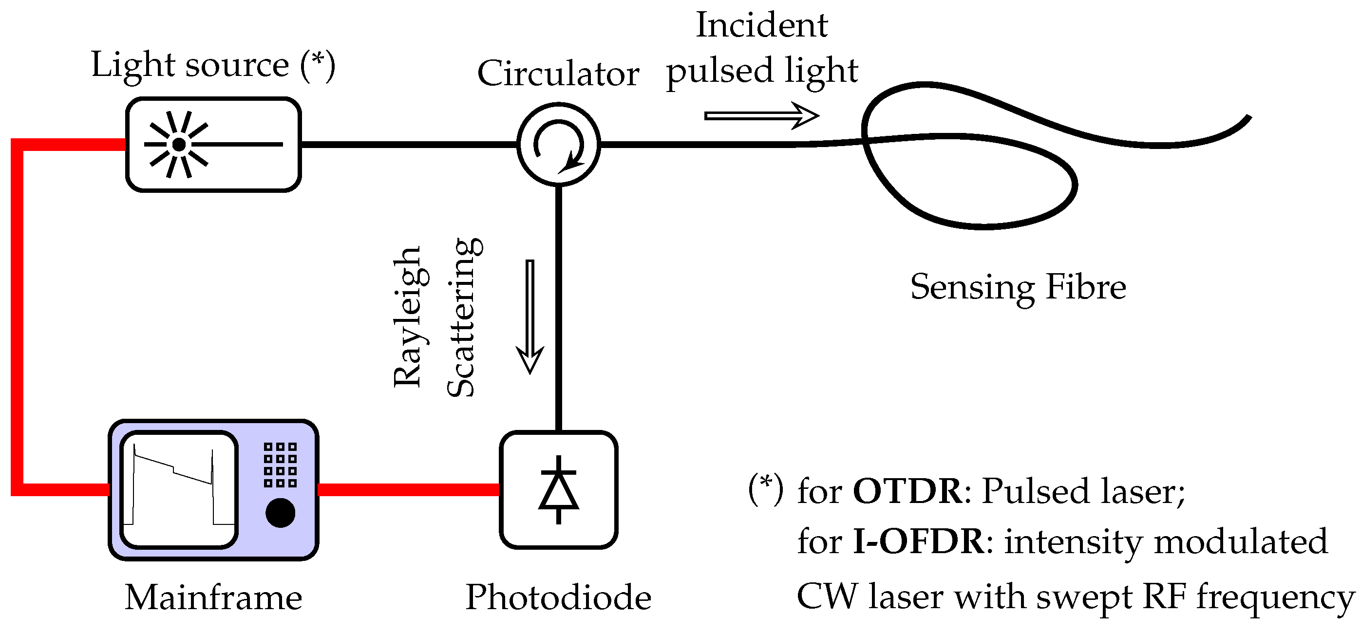
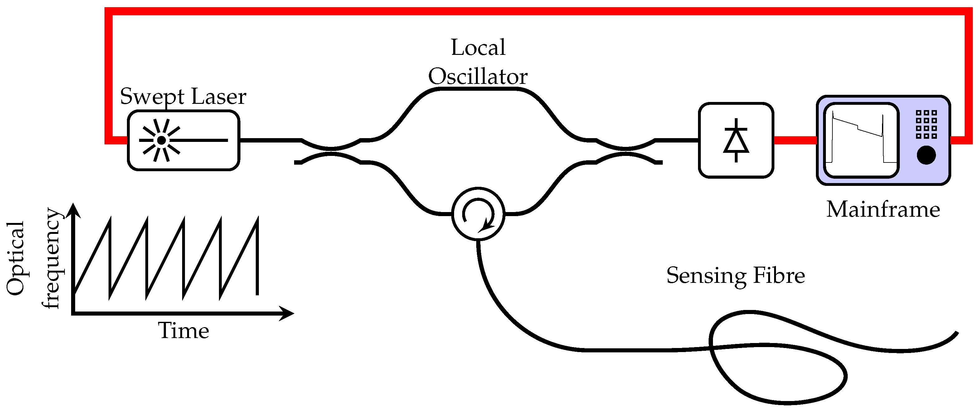
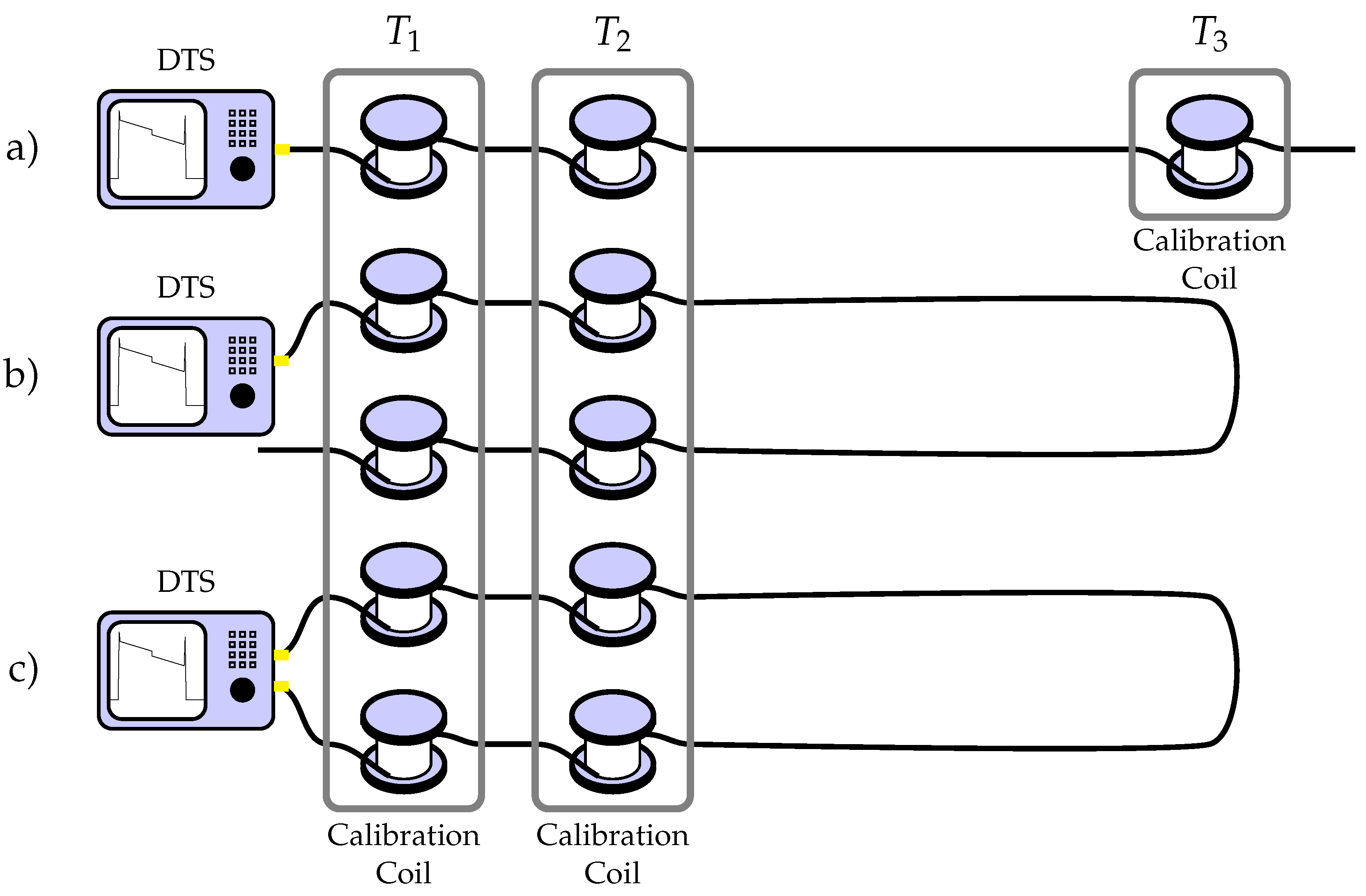
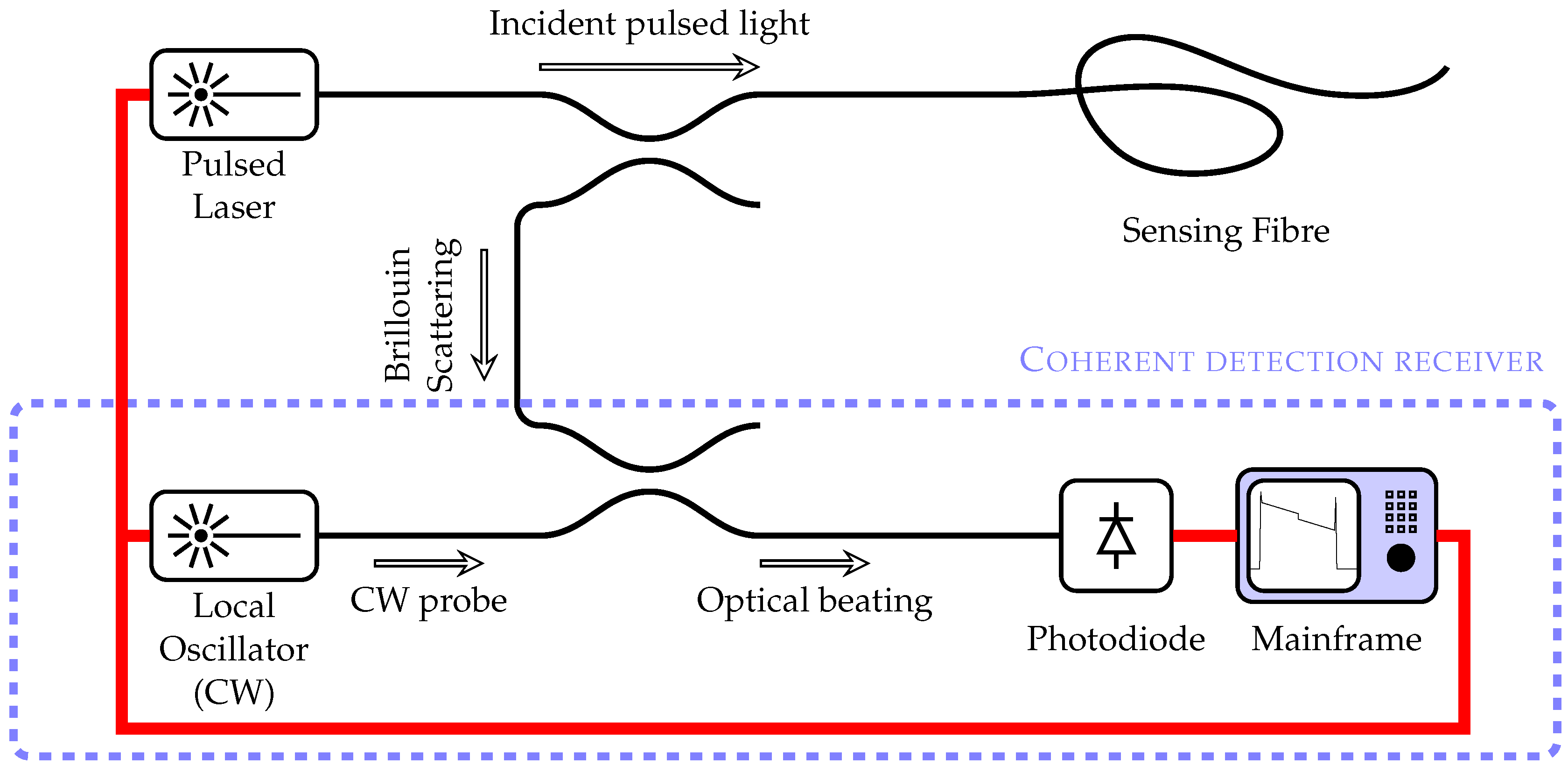
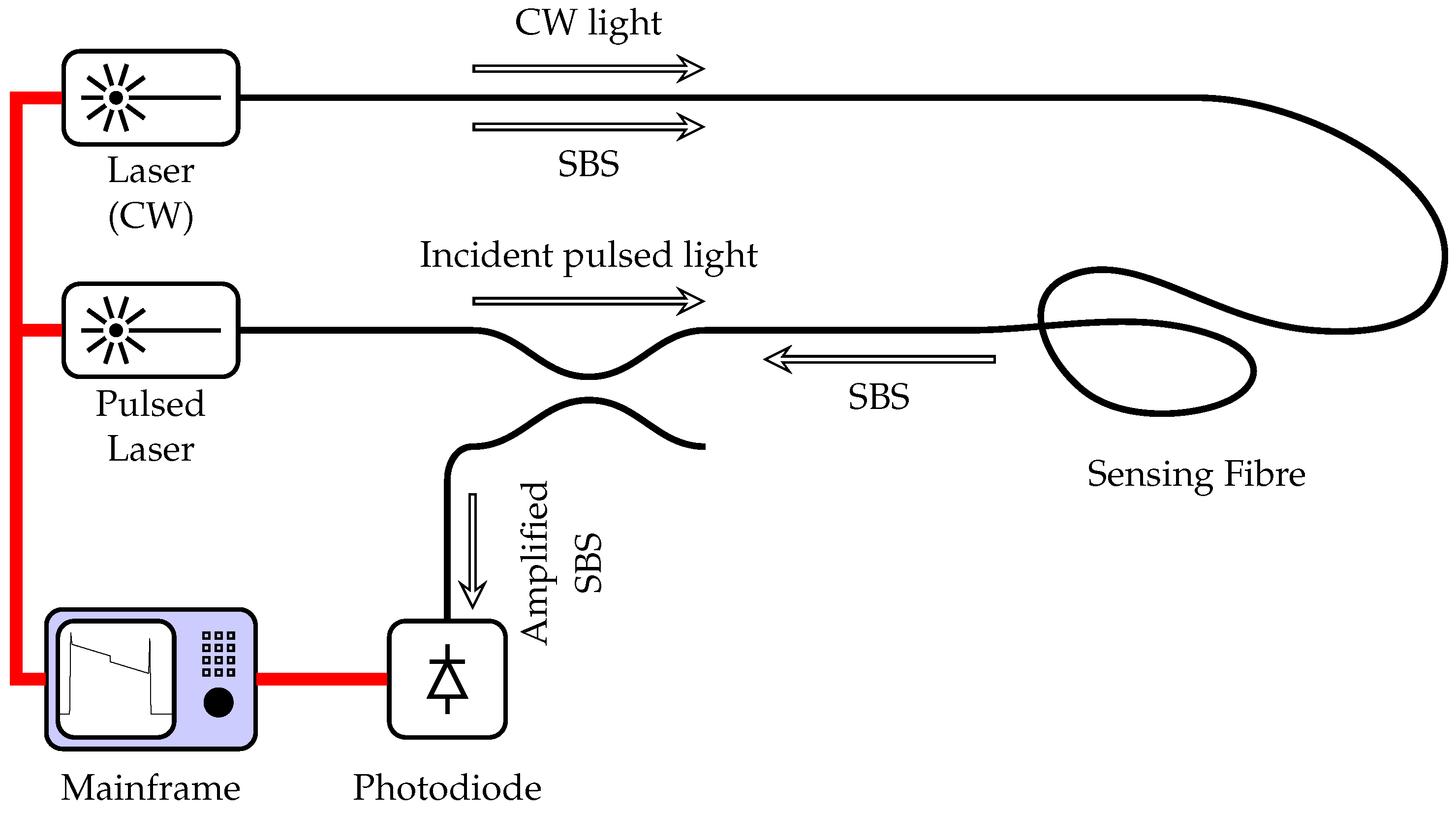
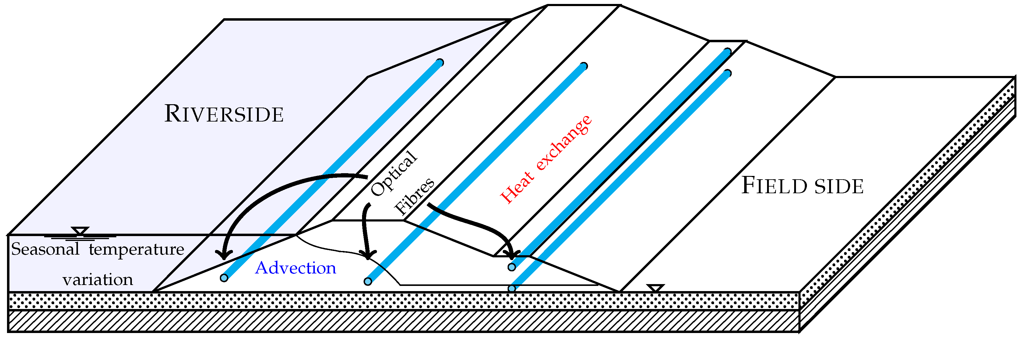
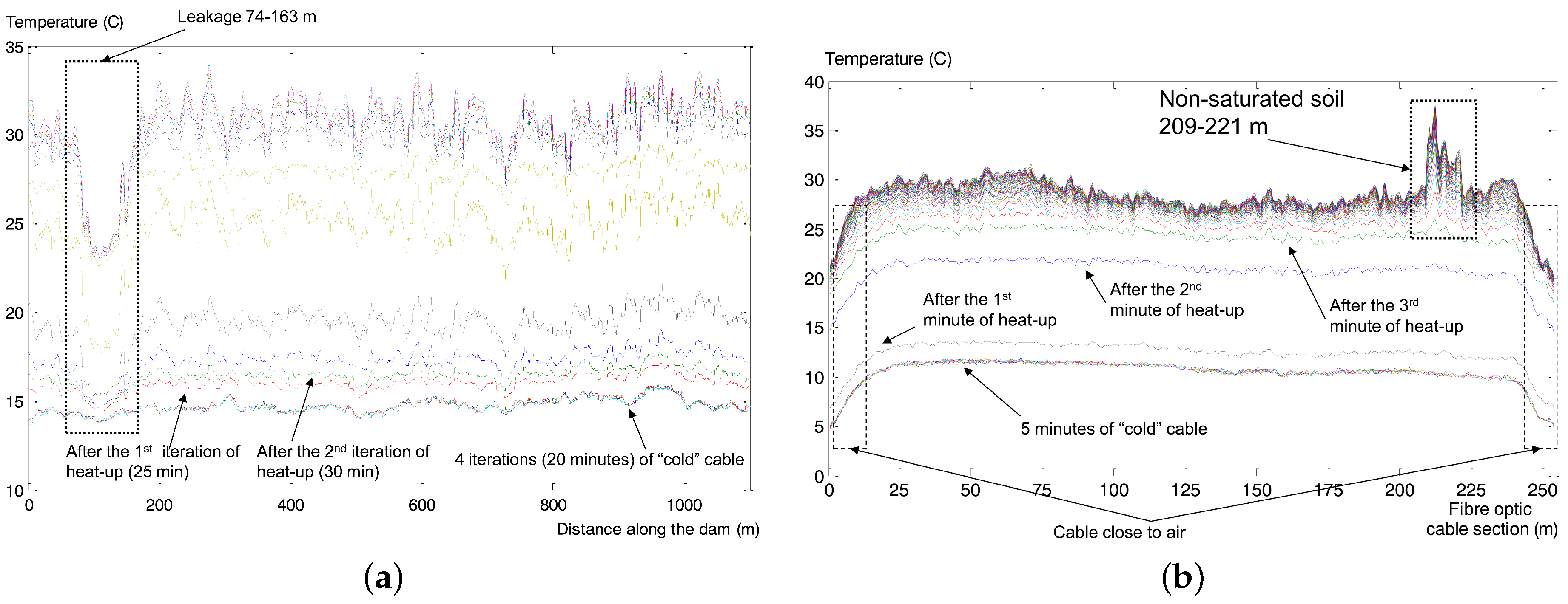
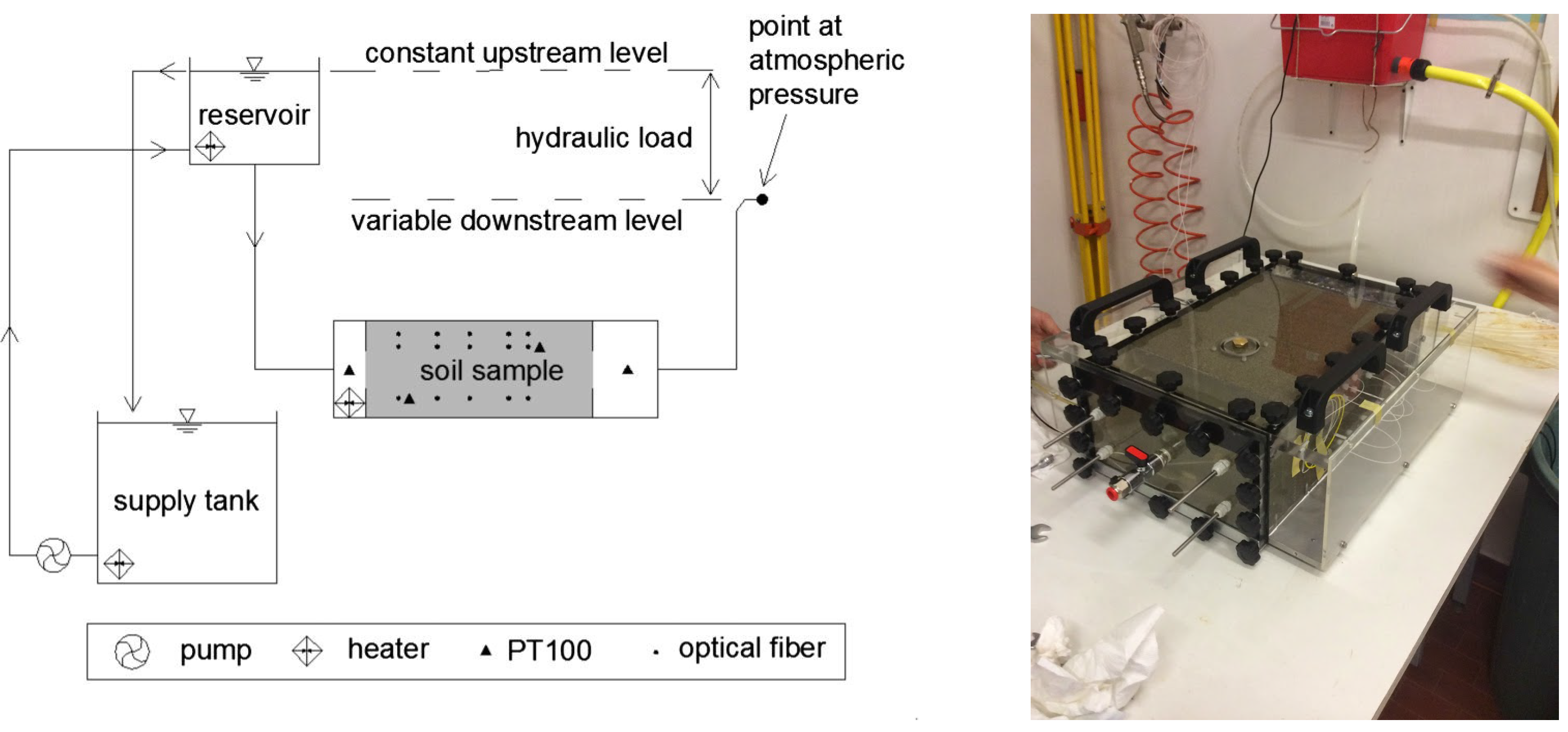
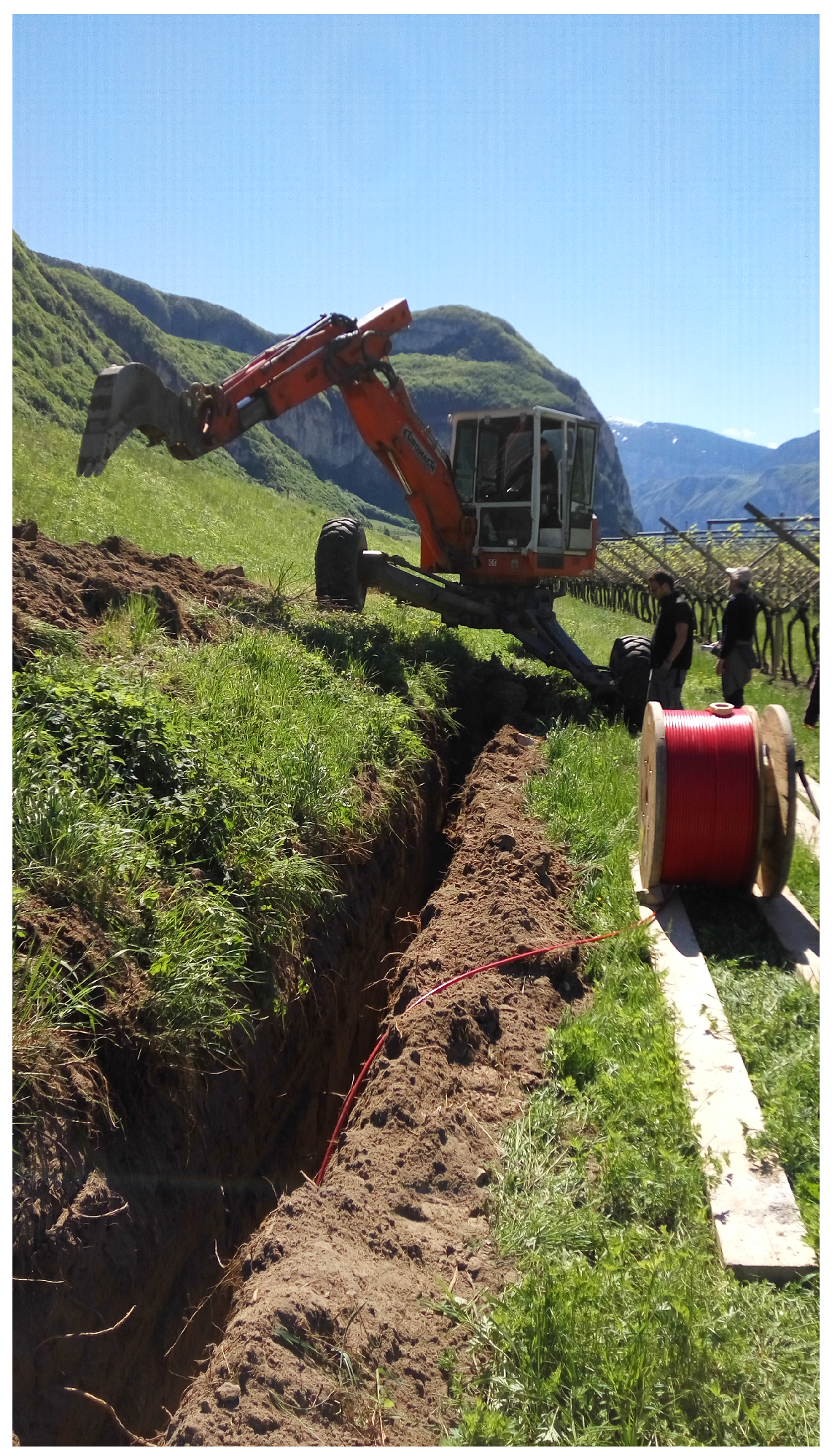
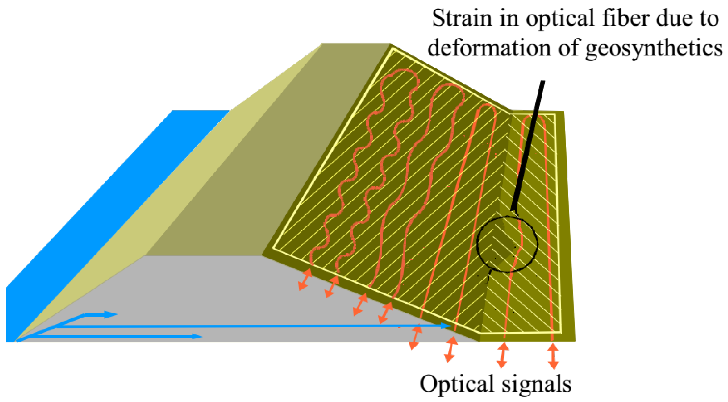
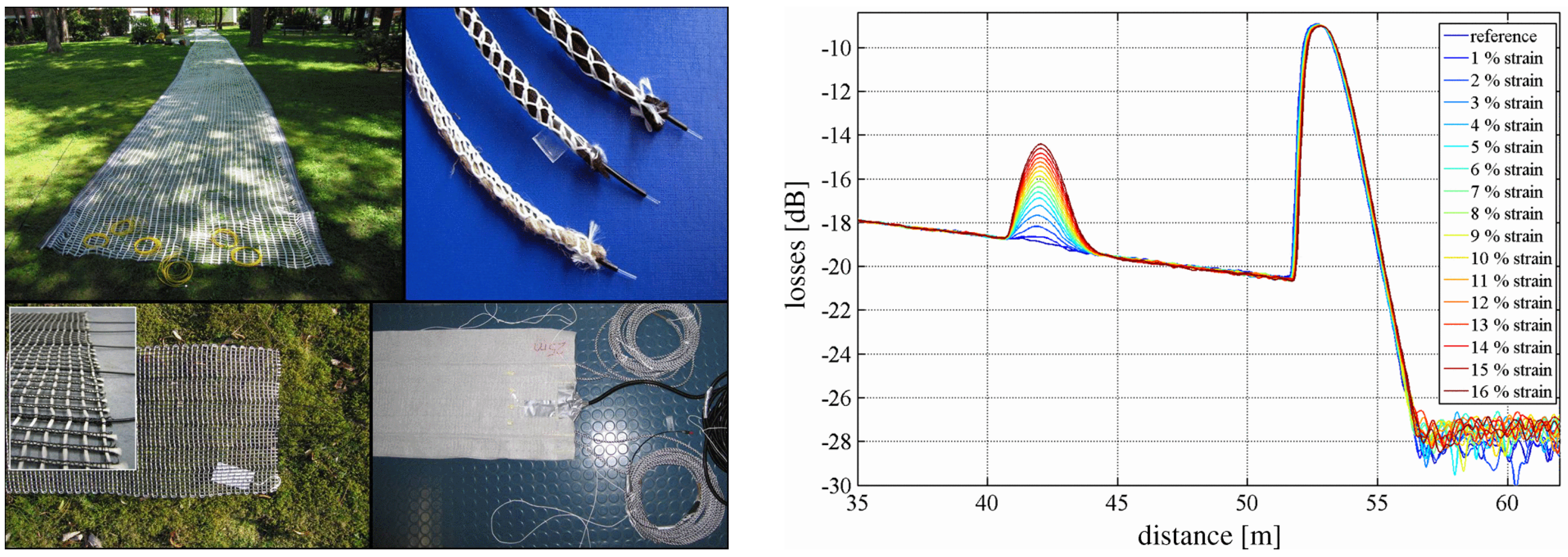
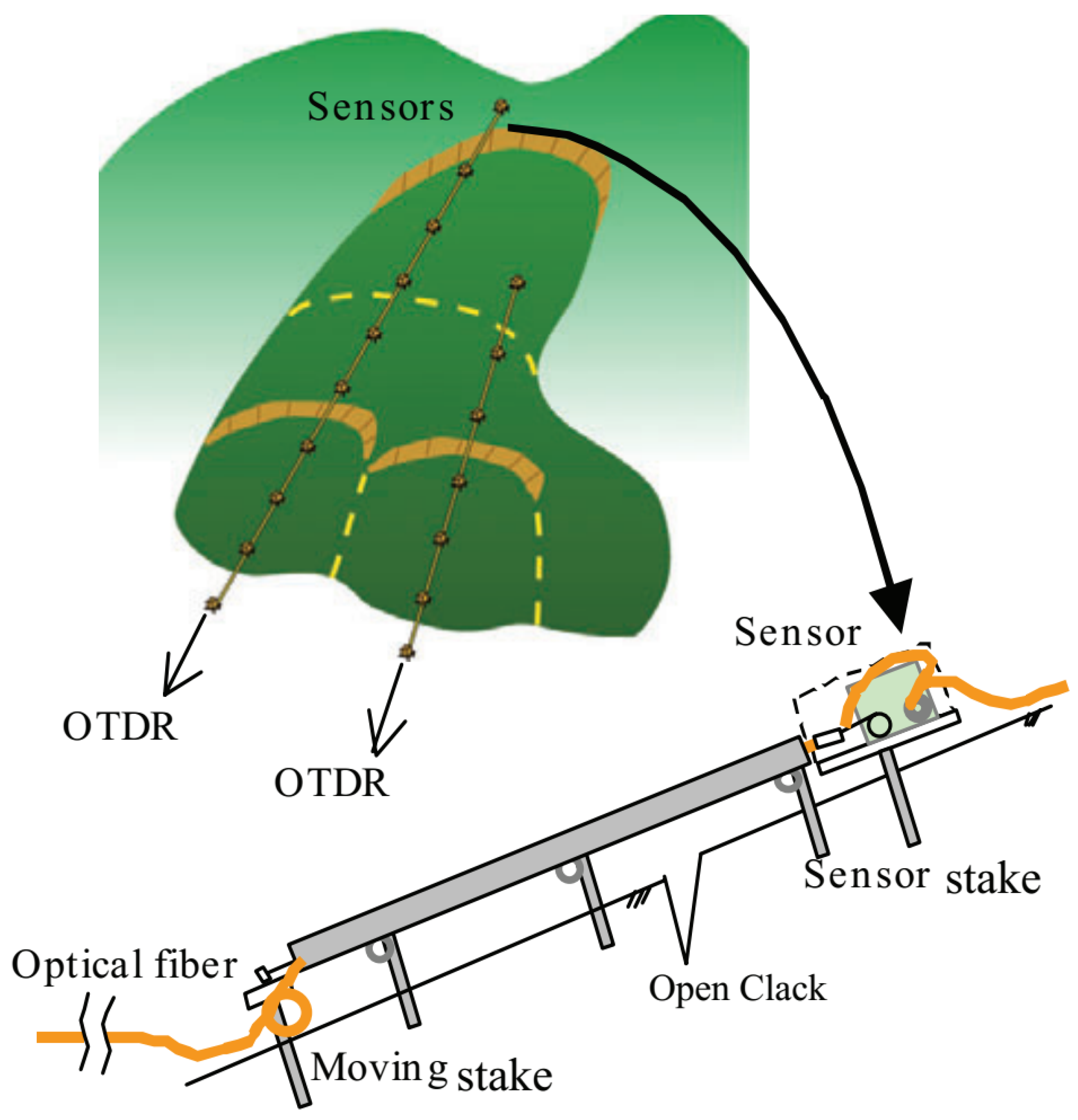
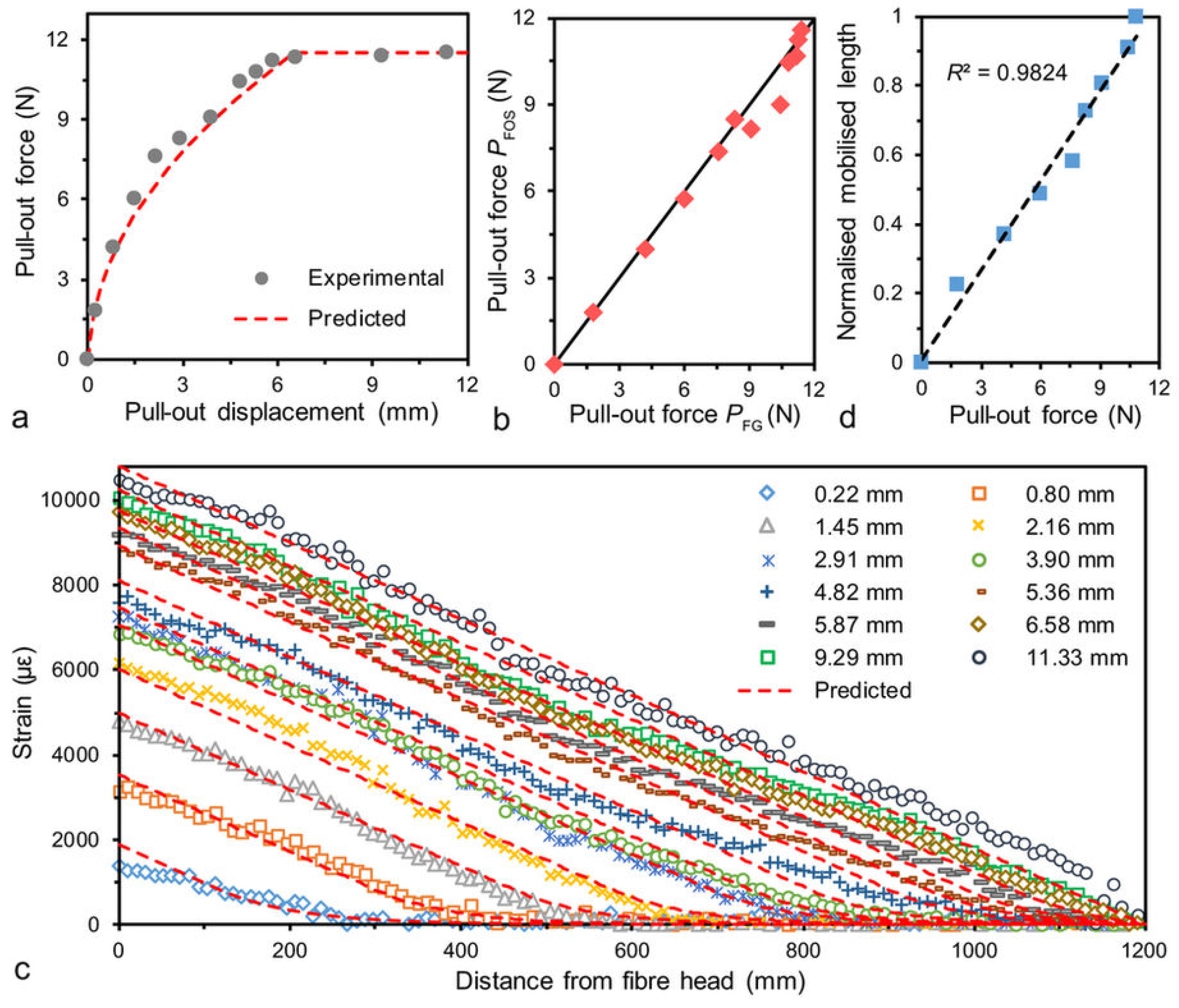
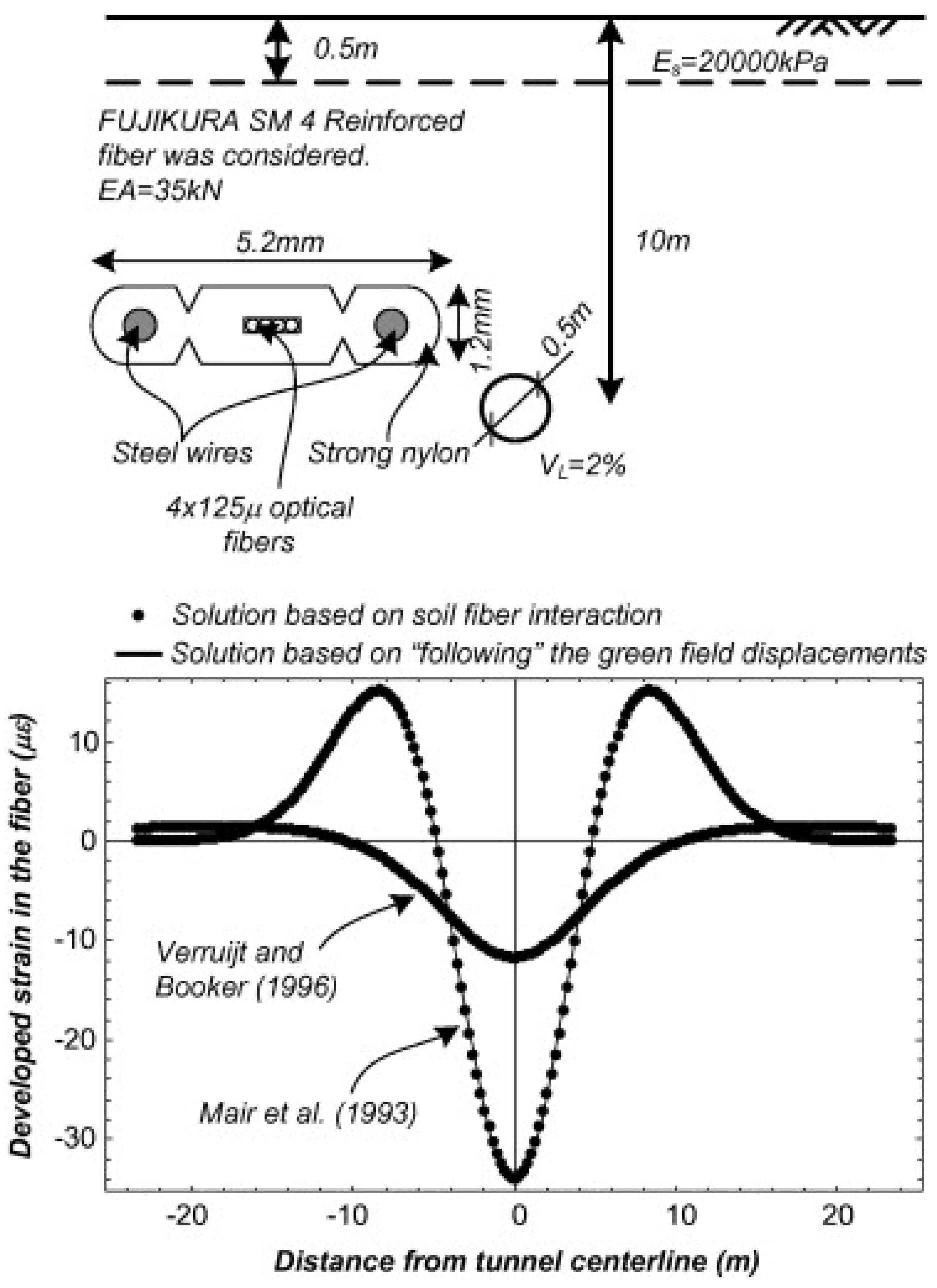
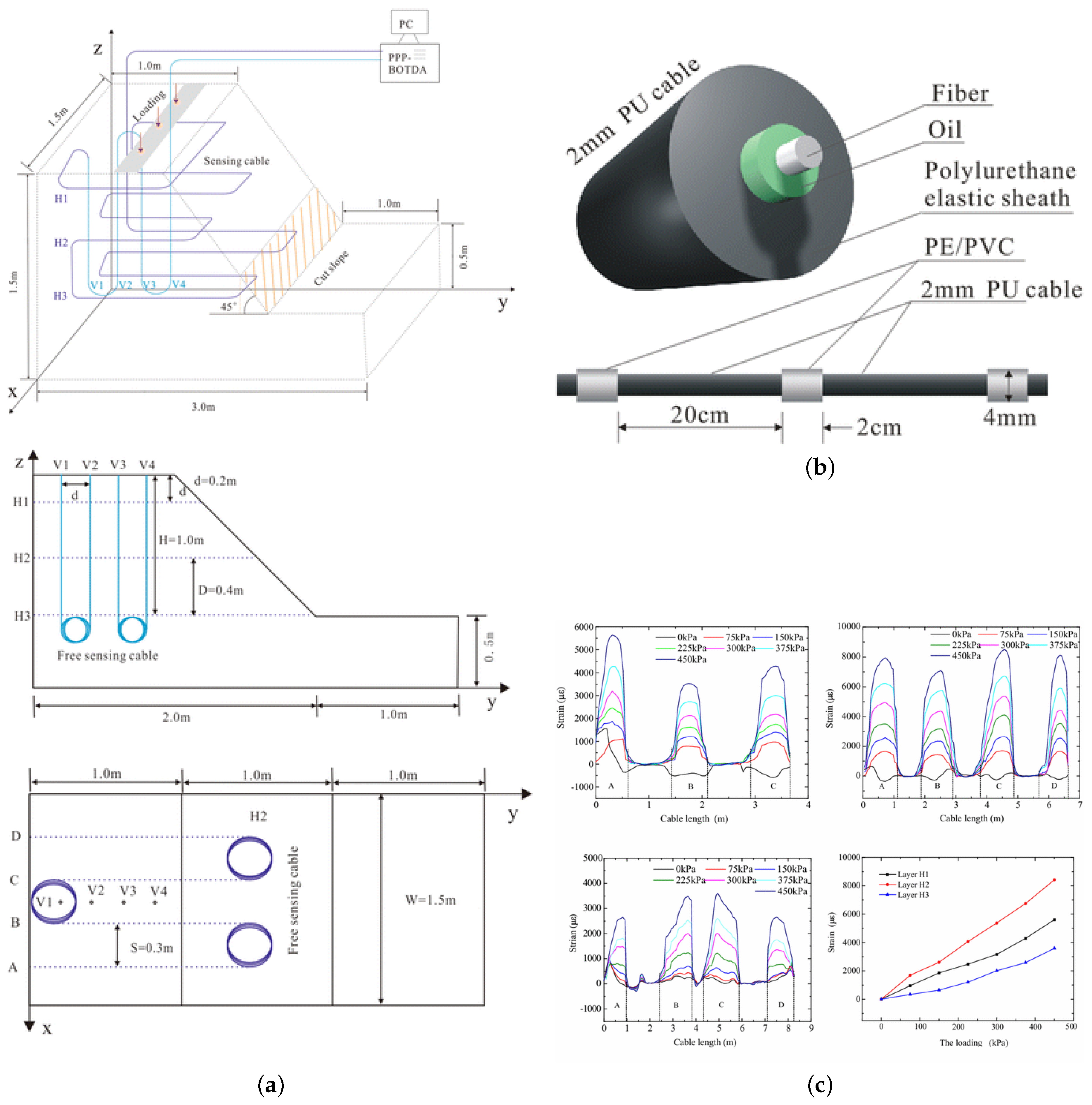
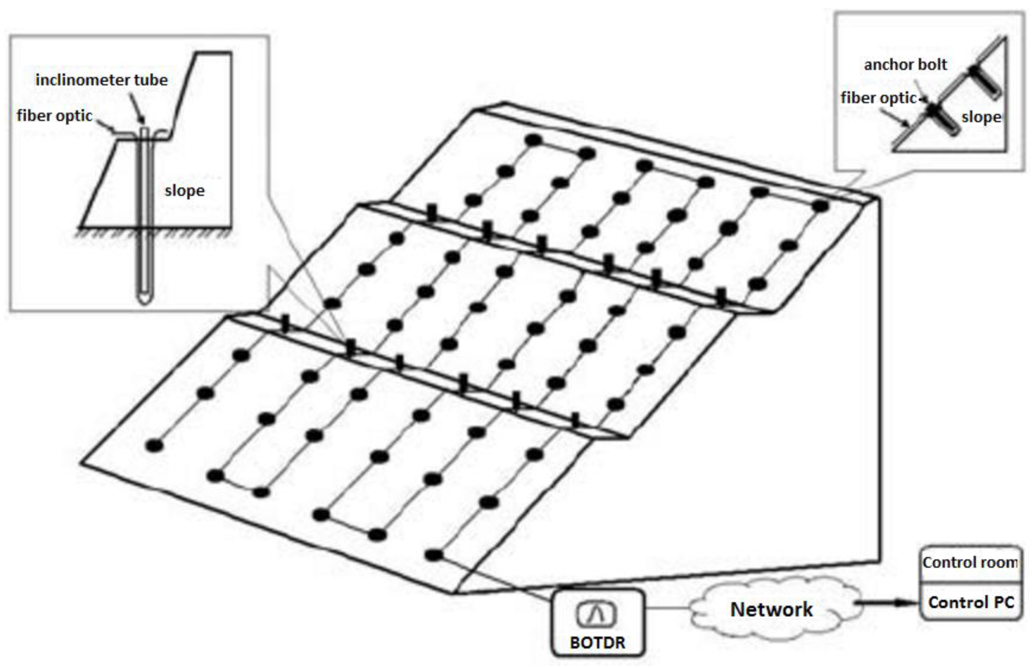
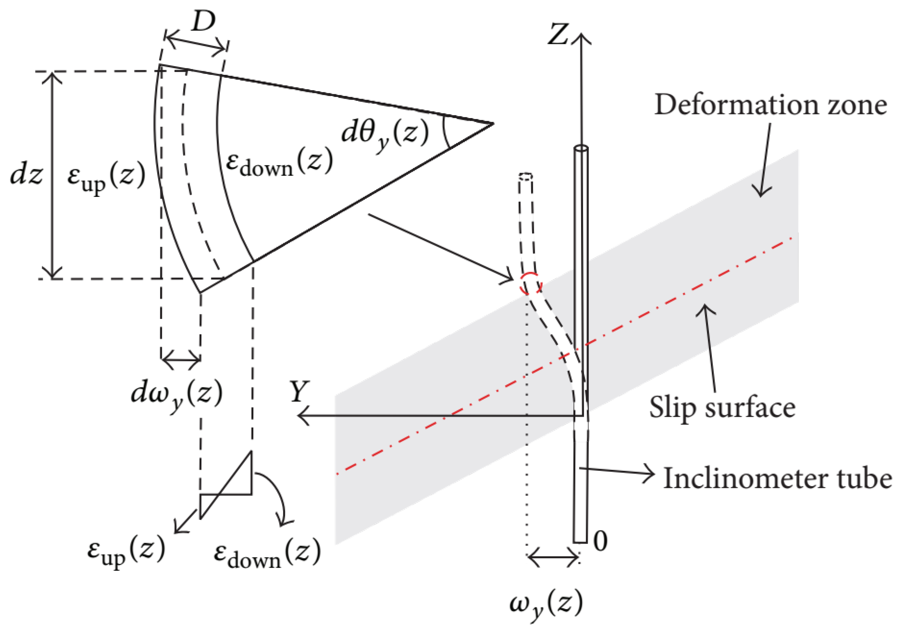
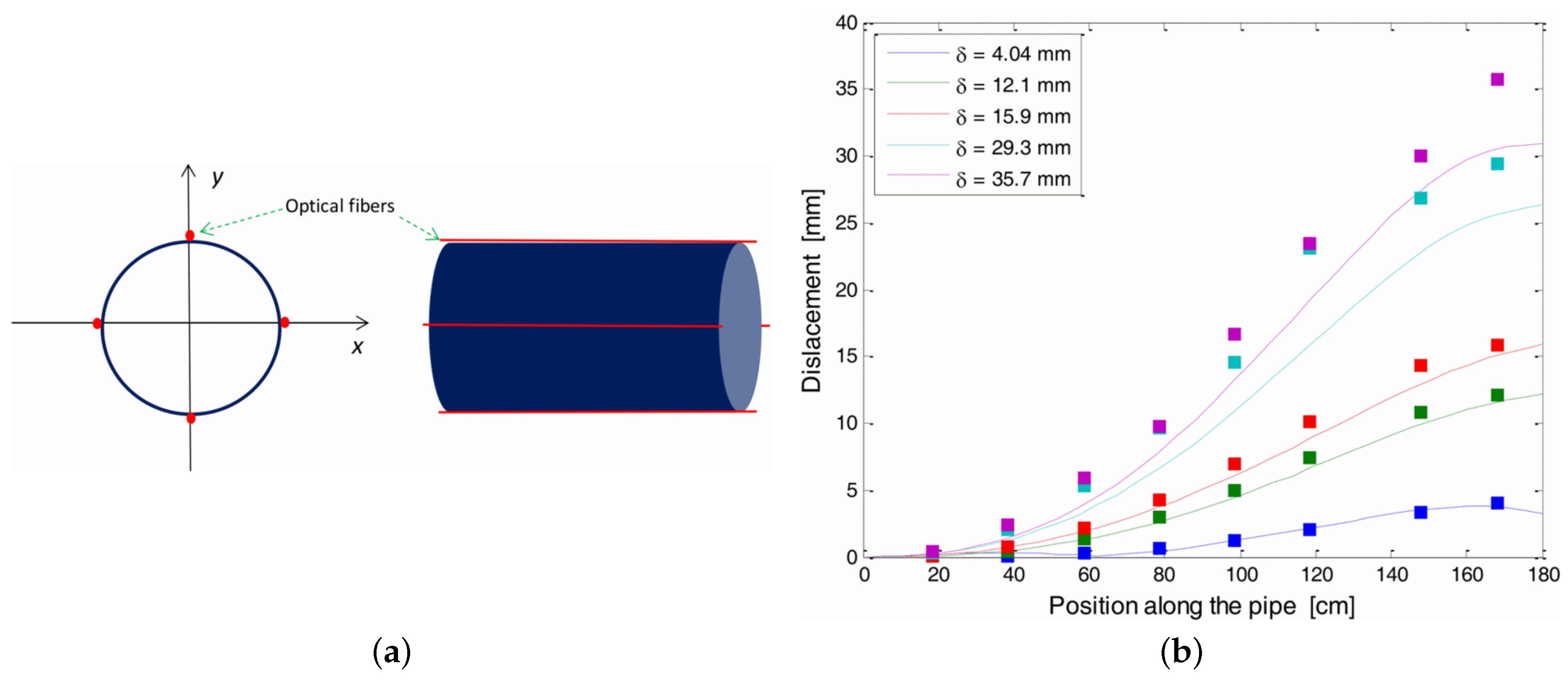
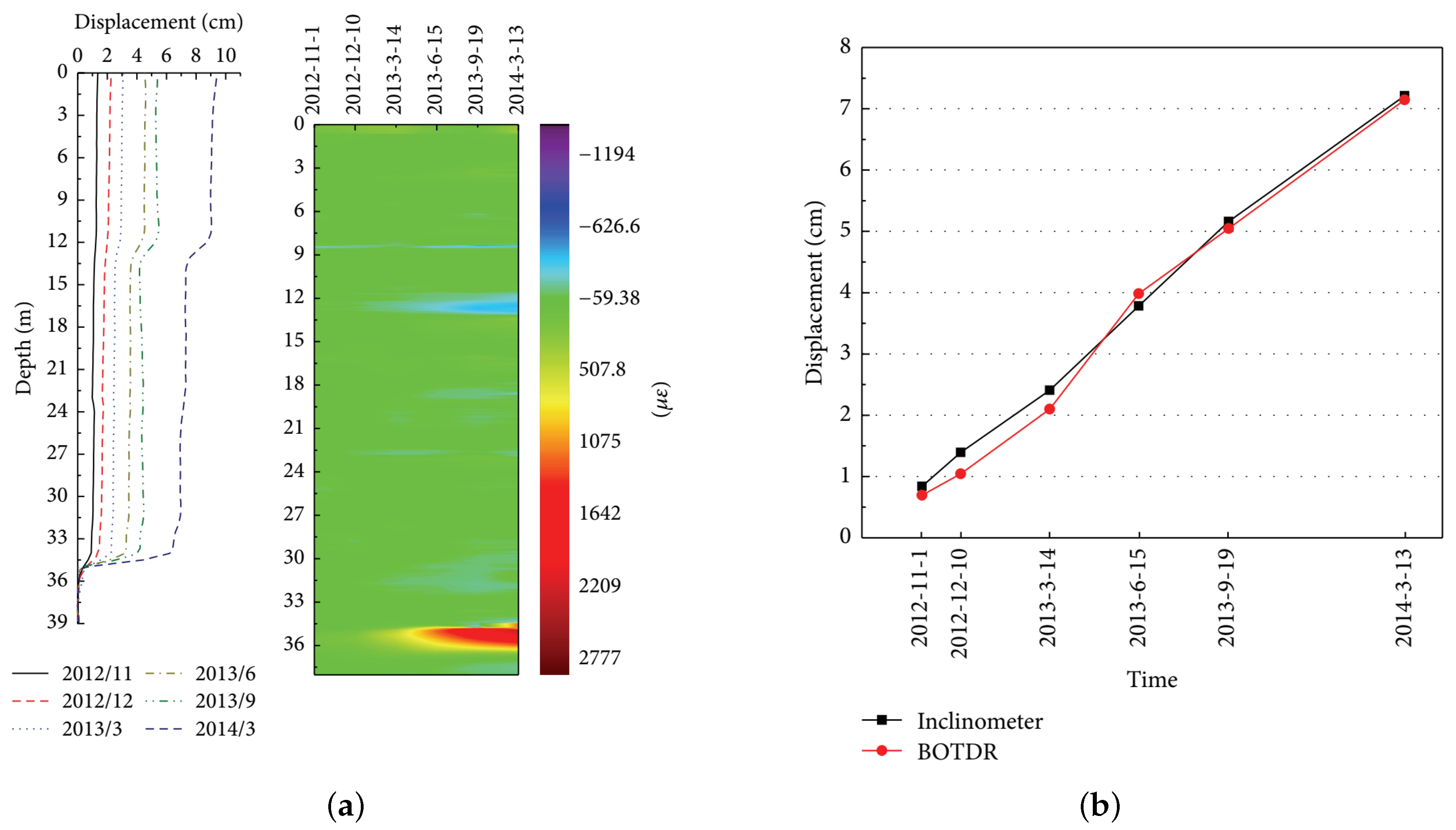
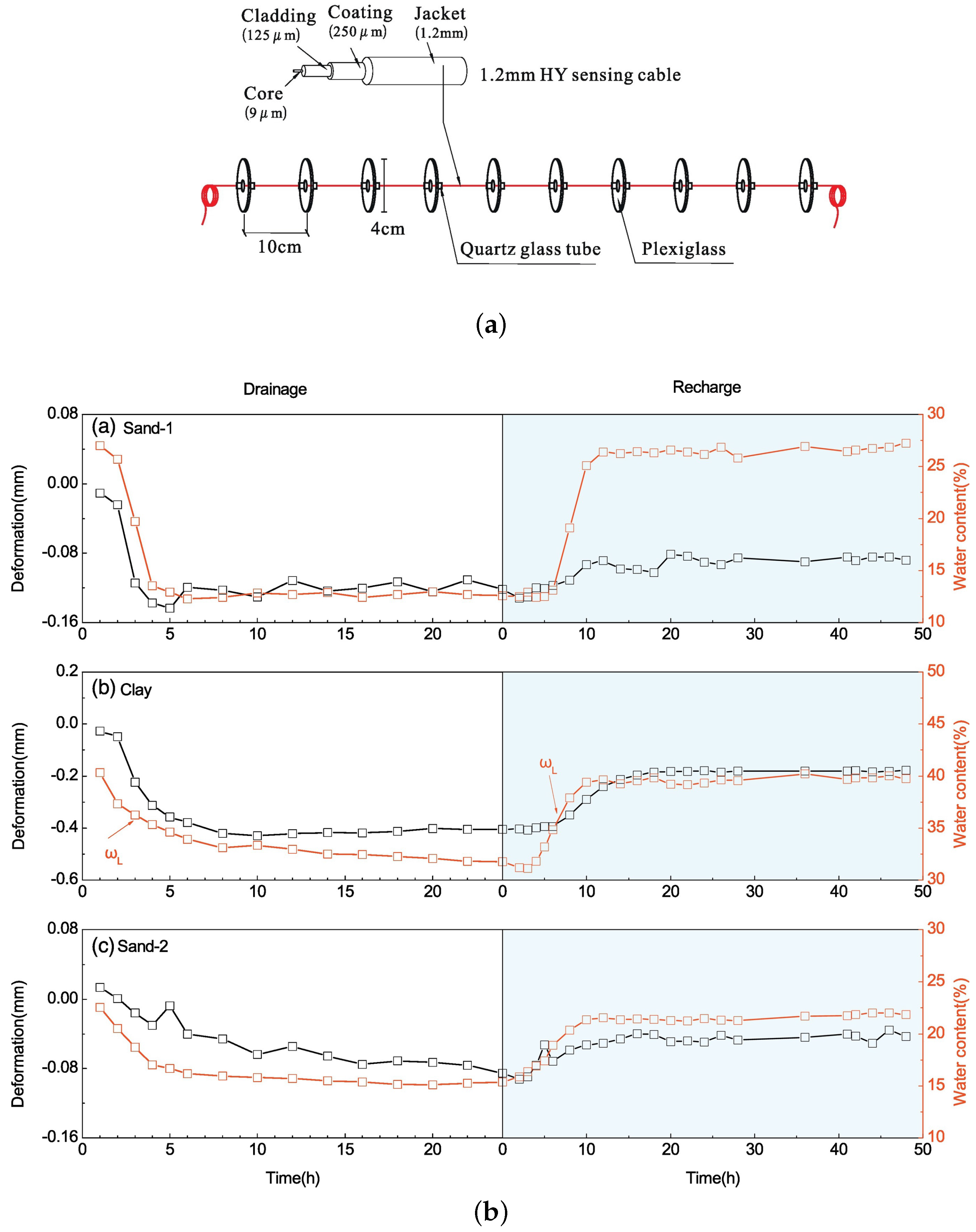
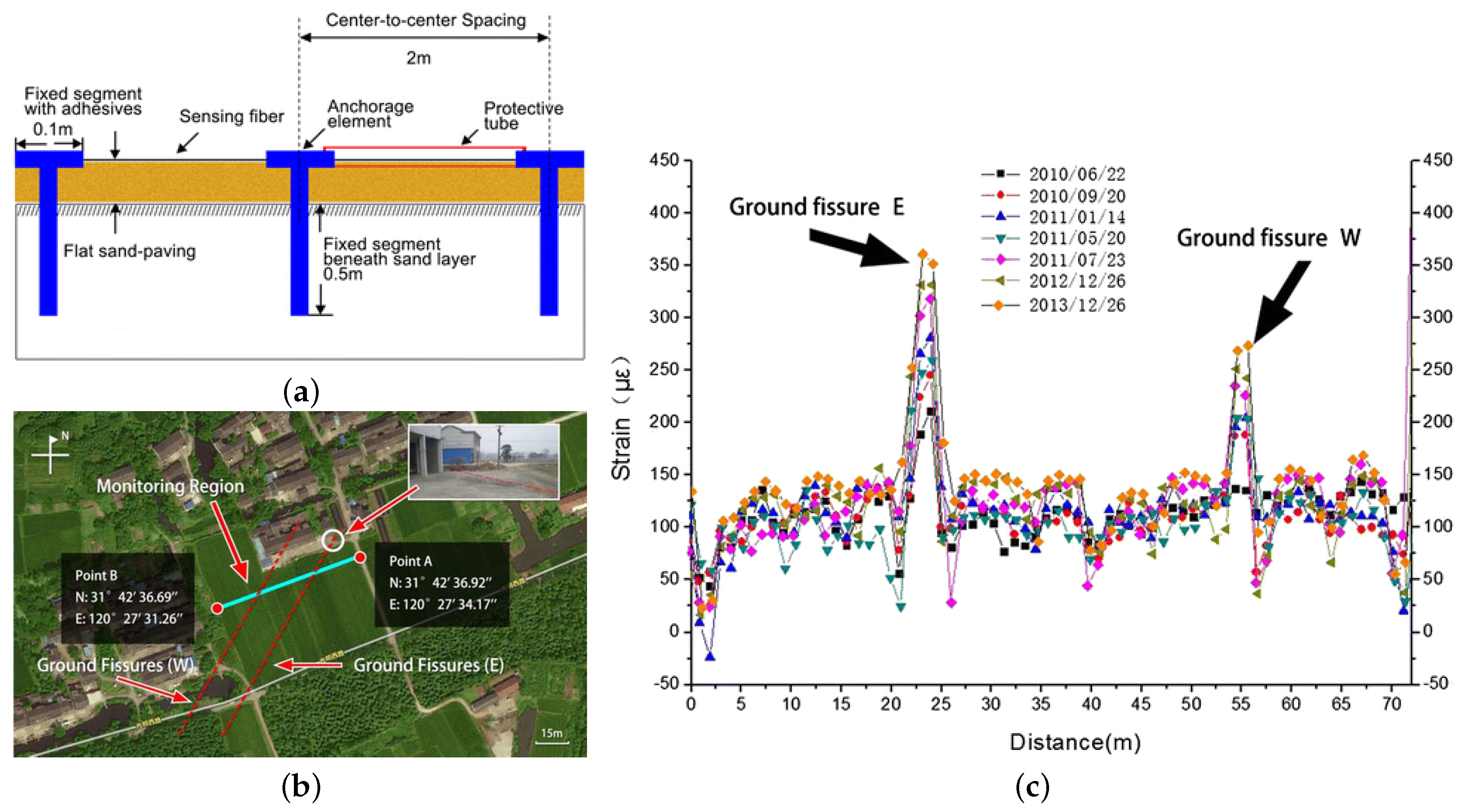
Table 1.
Performances of some commercial Rayleigh-based interrogators (sources: producers’ datasheets, technical notes, and scientific papers).
Table 1.
Performances of some commercial Rayleigh-based interrogators (sources: producers’ datasheets, technical notes, and scientific papers).
| Type | Fibre Type | Sensing Range | Spatial Resolution | Measurand | Measurand Resolution | Acquisition Time |
|---|---|---|---|---|---|---|
| -OTDR (*) | SMF/MMF/POF | 40 km (SMF) | 10 cm | n/a | n/a | minutes |
| -OTDR | SMF | 100 km | 5 m | Vibration | n/a (1 Hz–2.5 kHz) | n/a |
| SMF | up to 40 km | 4 m | n/a (0.1 Hz–20 kHz) | 20–500 s | ||
| OFDR | SMF | 30/70 m (†) | 1 cm | Temperature/Strain | 0.1 °C/1 | from 10 to 20 s |
| 2 km (†) | 3 cm | >0.5 °C/>4.1 | 6.5 s | |||
| SMF | 10 m | 5.2 mm | <0.1 °C/<1 | 0.1 s | ||
| SMF | 2 m | 5.2 mm | <0.1 °C/<1 | 4 ms | ||
| SMF | 10 m | 1.3 mm | <0.1 °C/<1 | 42 ms | ||
| POFDR (**) | SMF | 100 m | 2 mm | n/a | n/a | n/a |
* The device can directly sense strain in polymer optical fibre (POF), where an increase in the backscatter level with strain is observed [47]; ** The device performs a space resolved measurement of birefringence (transverse stress) and reflection. -OTDR: photon-counting OTDR; -OTDR: phase-OTDR; MMF: multi-mode fibre; POFDR: polarisation-sensitive OFDR; SMF: single-mode fibre; † These rows refer to the two different modes of operation of the same device.
Table 2.
Performances of some commercial DTS (sources: producers’ datasheets, technical notes, and scientific papers).
Table 2.
Performances of some commercial DTS (sources: producers’ datasheets, technical notes, and scientific papers).
| Type/Fibre Type | Operating Wavelength | Spatial Resolution | Sensing Range | Temperature Resolution | Acquisition Time |
|---|---|---|---|---|---|
| Short-range/MMF | 904 nm | 7.5 m | 2 km | 0.4 °C | 12 s |
| n/a | 3 km | 2 °C | 70 s | ||
| 975 nm | 2 m | 4 km | 0.1 °C () | 600 s | |
| 860 nm | n/a | 2 km | 1 °C () | 60 s | |
| Middle-range/MMF | 1064 nm | n/a | 5 km | 2 °C | 120 s |
| n/a | 12 km | 2 °C () | 600 s | ||
| 1.4 m | 5 km | 0.28 °C () | 10 s | ||
| 1.4 m | 8 km | 1 °C () | 10 s | ||
| 1.4 m | 10 km | 2.25 °C () | 10 s | ||
| 0.35 m | 5 km | 0.2 °C | 180 s | ||
| Long-range/SMF | 1550 nm | 5 m | 15 km | 1 °C | 600 s |
| 10 m | 30 km | 1.5 °C () | 600 s | ||
| 2 m | 30 km | 2.75 °C () | 10 s | ||
| n/a | 10 km | 1.2 °C () | 60 s | ||
| n/a | 32 km | 6.0 °C () | 300 s | ||
| n/a | 16 km | 1.8 °C () | 180 s | ||
| Raman OFDR/MMF | 980 nm | 1 m | 4 km | 0.80 °C | 200 s |
| 1.5 m | 0.29 °C | 158 s | |||
| 3 m | 0.88 °C | 27 s | |||
| 1480 nm | 3 m | 10 km | 3.0 °C | 60 s | |
| Raman OFDR/SMF | 1550 nm | 2 m | 30 km | 1.9 °C | 300 s |
| Pulse Compression | 1064 nm | 1.5 m | 4 km | 0.15 °C | 600 s |
| Raman/MMF | 8 km | 0.65 °C | 600 s |
Time to reach the indicated temperature resolution; Resolution at the maximum specified range.
Table 3.
Performances of some commercial BOTDR/BOTDA systems (sources: producers’ datasheets, technical notes, and scientific papers).
Table 3.
Performances of some commercial BOTDR/BOTDA systems (sources: producers’ datasheets, technical notes, and scientific papers).
| Type | Spatial Resolution | Sensing Range | Temperature Resolution/ Repeatability | Strain Resolution/ Repeatability | Acquisition Time |
|---|---|---|---|---|---|
| BOTDR | 5 m | 45 km | 0.1 °C/3 °C | / | 1800 s |
| 80 m | 70 km | 0.005 °C/2 °C | / | n/a | |
| 22 m | 80 km | n/a | / | n/a | |
| 110 m | 80 km | n/a | / | n/a | |
| 11 m | 55 km | n/a | / | n/a | |
| BOTDA | 4 m | 60 km (120 km loop) | 0.1 °C/1 °C | / | 600 s |
| 1.5 m | 10 km (20 km loop) | 0.1 °C/1 °C | / | 4 s | |
| 20 m | 30 km (60 km loop) | 0.1 °C/n/a | /n/a | 600 s | |
| BOTDA (*) | 50 m | 50 km (100 km loop) | 0.005 °C/0.1 °C | / | 100 s |
Time to reach the indicated temperature resolution; Resolution at the maximum specified range; * This device can measure both temperature and strain separately.
© 2017 by the author. Licensee MDPI, Basel, Switzerland. This article is an open access article distributed under the terms and conditions of the Creative Commons Attribution (CC BY) license (http://creativecommons.org/licenses/by/4.0/).
Share and Cite
MDPI and ACS Style
Schenato, L. A Review of Distributed Fibre Optic Sensors for Geo-Hydrological Applications. Appl. Sci. 2017, 7, 896. https://doi.org/10.3390/app7090896
AMA Style
Schenato L. A Review of Distributed Fibre Optic Sensors for Geo-Hydrological Applications. Applied Sciences. 2017; 7(9):896. https://doi.org/10.3390/app7090896
Chicago/Turabian StyleSchenato, Luca. 2017. "A Review of Distributed Fibre Optic Sensors for Geo-Hydrological Applications" Applied Sciences 7, no. 9: 896. https://doi.org/10.3390/app7090896
Note that from the first issue of 2016, this journal uses article numbers instead of page numbers. See further details here.