Investigation of Laser Cutting Width of LiCoO2 Coated Aluminum for Lithium-Ion Batteries


1
Department of Mechanical and Automotive Engineering, Kongju National University, Cheonan 31080, Korea
2
Department of Laser and Electron Beam Application, Korean Institute of Machinery & Materials (KIMM), Daejeon 34103, Korea
*
Author to whom correspondence should be addressed.
Appl. Sci. 2017, 7(9), 914; https://doi.org/10.3390/app7090914
Submission received: 25 July 2017
/
Revised: 30 August 2017
/
Accepted: 31 August 2017
/
Published: 6 September 2017
(This article belongs to the Special Issue Electrode Materials for Lithium-ion Batteries/Super-capacitors)
Abstract
:Lithium-ion batteries are widely used for many applications such as portable electronic devices and Electric Vehicles, because they have lighter weight, higher energy density, higher power density, and a higher energy-to-weight ratio than other types of batteries. Conventional contact-based cutting technology may be inefficient whenever cell design is changed since lithium-ion battery cells are not standardized. Furthermore, the conventional cutting may result in process instability and a poor cut quality due to the tool wear so that it leads to short circuits and local heat generation. These process instability and inefficiency may be solved by laser cutting due to advantages such as clean cutting edge, less deformation, applicability to almost all materials, possibility of precision processing, and easy modification of cutting path. Despite the importance of the laser cutting research, no clear definition of cutting widths has been presented, and there is lack of knowledge to understand the effect of laser parameters on cutting widths. Therefore, this research examines the surface of cathode cut by a laser and defines cutting widths such as top width, melting width, and kerf width. The relationship between the laser parameters and cutting characteristics with defined widths are studied. When the volume energy is less than , no active electrode material is removed. When the laser power is greater or equal to 100 W, both the top and melting widths are clearly observed. The laser power of 50 W can selectively ablate the active electrode material with the material removal rate of 32.14–55.71 . The threshold volume energy to fully penetrate the 50 μm-thick current collector is between . All clearance width is less than 20 μm, while the clearance width interestingly exceeds 20 μm when the laser power is 200 W. The effect of material properties on heat transfer using the one dimensional transient semi-infinite conduction model is investigated. In addition, five types of physical characteristics are defined and discussed.
1. Introduction
Lithium-ion batteries, which are secondary batteries, are used for portable electronic devices, Electric Vehicles (EV), and Plug-in Hybrid Electric Vehicles (PHEV), because they are lighter and have a higher energy density, power density, and energy-to-weight ratio than lead-acid batteries and nickel-cadmium batteries [1,2]. Due to these advantages, material research on lithium-ion batteries has been actively done to improve battery performances [3]. However, the performance of the lithium-ion battery can be also affected by the manufacturing processes. Lithium-ion batteries’ cell design is not standardized because their shapes and capacities are different according to their applications and requirements. Therefore, conventional cutting technology such as die cutting and rotary knife slitting may be inefficient since tools need to be re-designed so that an additional manufacturing cost is required whenever the cell design changes. Furthermore, the conventional cutting technology may result in process instability and poor cut quality due to the tool wear. Therefore, this poor cut quality leads to short circuits and local heat concentration [2]. This process instability and inefficiency may be solved by laser processing since it has many advantages, such as a clean cutting edge, less deformation, applicability to almost all materials, possibility of precision processing, and an easy transition of cutting path [4,5,6,7,8,9].
Lee et al. [2,10,11] proposed a mathematical model to understand multi-physical phenomena during the laser cutting of electrodes using a single mode fiber laser. This mathematical model is used to investigate the laser cutting on current collectors such as copper and aluminum [2], and composite laser cutting such as anode and cathode [10,11]. Furthermore, laser parameters are experimentally optimized for high speed remote laser cutting [12]. Lutey et al. [13] characterized the process efficiency and quality for laser cutting of lithium iron phosphate battery electrodes. They found that the cutting efficiency increases with shorter pulses, higher velocity, and shorter wavelength. Furthermore, in his recent publication, high speed laser cutting of Li-ion battery electrodes had been investigated to provide guidelines for the processing parameters to achieve optimum process efficiency and visible cut quality with a high power nanosecond pulsed laser [14]. Schmieder [15] proposed an analytical model to understand the laser ablation mechanism of lithium-ion battery coating. This model was verified by a time resolved shadowgraph imaging and experiments. Among this research, no clear definition of cutting widths has been presented and there is lack of knowledge to understand the effect of laser parameters on cutting widths. Therefore, this research examines the surface morphology of cathode cut by a laser and defines meaningful cutting widths. The relationship between laser parameters and cutting widths are studied. Furthermore, the material removal rate of active electrode material and the clearance width of cathodes are calculated by the defined widths. In addition, five types of physical characteristics with a cross-sectional view are defined and discussed with volume energy and cut surface images. Moreover, the effect of material properties on heat transfer using a one dimensional transient semi-infinite conduction model is presented. This paper is organized as follows. First, an experimental setup, procedures, and material information are described. Second, cutting widths are defined, as well as cut surface is investigated and discussed. Finally, the conclusions drawn from this study are summarized.
2. Experimental Set-Up and Cathode Materials
Single-mode Quasi-CW Ytterbium Fiber Laser (IPG YLM-200/2000-QCW) is used with CW mode in this experiment. Its M2 value is 1.05. The wavelength is 1070 nm and the maximum average output power is 250 W. The cathode sample with a thickness of 50 μm is used in the experiment, as shown in Figure 1. The current collector material is aluminum and its thickness is 20 μm. Major cathode manufacturing parameters are tabulated in Table 1. The active electrode material consists of 90% of LiCoO2, 5% SuperC65 (Conducting agent), and 5% of polyvinylidene fluoride (binder). The thickness of the active electrode material is coated on the current collector with the thickness of 30 μm. It is noted that the total thickness of this cathode is relatively thin for high power applications. Since this study proposes a systematic analysis, this method will be applied to the laser cutting of thicker cathode and the transferability of this method will be tested for the future research. Figure 1 shows the experimental settings. The cathode specimen is fixed at the both ends, with fixtures placed at the top and bottom. Thus, the gap between the workpiece and the plate prevents the effect of thermal conduction between the workpiece and plate below. Vertical distance from the F-theta lens to the surface is set to be 100 mm. The laser spot size at focus is 23 μm. The width of the cathode sample is 30 mm, and the cutting distance is 20 mm so that even though the laser cut sample is completely separated, the rest of the sample remains attached. Laser cutting is performed by changing the laser power and speed. Laser power is varied from 50 W to 250 W by an increment of 50 W. Laser scanning speed is changed from 500 mm/s to 5000 mm/s by an increment of 500 mm/s. Scanning Electron Microscope (SEM) is utilized to observe the cut surface of the laser-cutting sample.
3. Result and Discussion
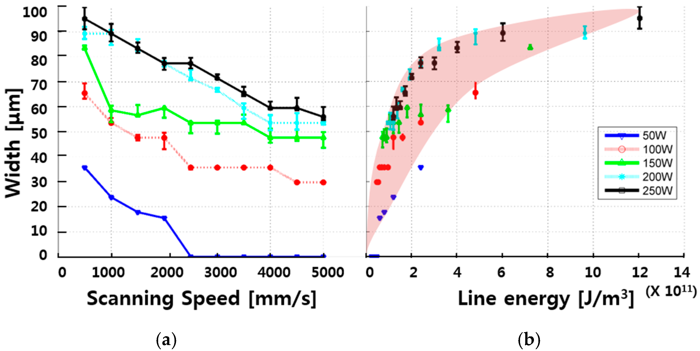
The cutting width of the laser cut samples can be defined by Top Width, Melting Width, and Kerf Width. Each width is shown in Figure 2. The top width is the width where the active electrode material is ablated by the laser, the melting width is the width where the current collector is melted with melting marks, and the kerf width is the width where the all layers are fully separated. Figure 3, Figure 4, Figure 5 and Figure 6 show the change of the widths depending on the laser parameters. The Y axis shows the width, and the X axis of the graph is the laser cutting speed (a) and volume energy (b). The volume energy () is defined as follows
where is a laser power, is scanning speed, and is a laser spot area. This volume energy can be defined also as dividing laser power by scanning speed. This study takes the former definition, which considers both the laser intensity and scanning speed, since the laser intensity is a more effective parameter than the laser power for cutting applications. Figure 3 shows the variation of top width depending on the scanning speed (a) and volume energy (b). As the laser scanning speed increases, the top width decreases. No top width is observed when the laser scanning speed is greater than 2500 mm/s when the laser power is 50 W. According to Figure 3b, the top width increases as the volume energy increases. However, when the volume energy is less than , no active electrode material is removed. Therefore, the threshold of the volume energy to the remove active electrode material is between . In addition, two regions are observed with two different slopes. Since the slope decreases, we expect that plasma may be formed and affect to the cutting process [16]. Not only this plasma formation, but also the complete penetration of the sample may affect to the slope decrease.
Figure 4a shows the melting width depending on the laser scanning speed and laser power. The melting width decreases as the scanning speed increases, which is a very similar trend to the top width. The melting width is always observed when the laser power is between 100 W and 250 W. However, no melting is observed when the laser power is 50 W. When the laser power is greater or equal to 100 W, both the top and melting widths are clearly observed. This indicates that the volume energy under these laser power and scanning speed is enough to remove the active electrode material. On the other hand, it is only the top width that is observed when the laser scanning speed is less than 2500 mm/s and the laser power is 50 W. This indicates that there is not enough volume energy to remove the active electrode material. For the laser power of 50 W, it is assumed that the top width is invariable in depth and material removal rate can be calculated as follows
where is depth, is top width, and is velocity. The material removal rates, when the laser scanning speed is 500 mm/s, 1000 mm/s, 1500 mm/s, and 2000 mm/s, are 32.14 , 42.86, 48.21, and 55.71 , respectively. When the results are examined from the laser ablation point of view, the laser power of 50 W can selectively ablate the active electrode material with the material removal rate of 32.14–55.71 .
The kerf width, depending on the laser scanning speed, is shown in Figure 5a. Figure 5b shows the variation of the kerf width depending on the volume energy. It is noted that the cathode is fully separated with the laser speed of 5 m/s and laser power of 150 W. As the scanning speed becomes faster, the kerf width decreases. When the laser power is greater than 100 W, the kerf width is observed under all laser scanning speeds applied in this study. It is obvious that no kerf width is observed with the laser power of 50 W since there is no melting and no ablation. With the laser power of 100 W, kerf width is observable when the laser scanning speed is less than 3000 mm/s. Therefore, the observation from Figure 4 and Figure 5 lead to the conclusion that the threshold volume energy to fully penetrate the 50 μm-thick current collector is between .
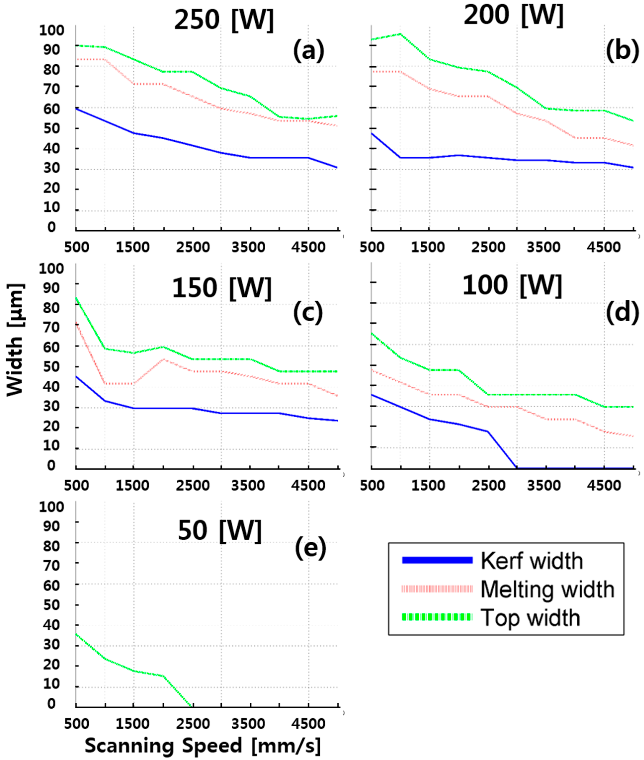
All widths defined in this study are compared together with the fixed laser power, as shown in Figure 6. SEM images after laser cutting is shown in Figure 7, Figure 8, Figure 9, Figure 10, Figure 11 and Figure 12. Although all widths decrease as the scanning speed increases, as shown in Figure 6a–c, the change rate is different. The changing rates of the top and melting width are greater than that of the kerf width. This means that the material removal rate of the active electrode material is greater than that of the current collector. From the observation of the changing rates, we can presume that the absorbred laser energy is transferred more rapidly in the region of the active electrode material than that of current collector. This can be explained by examining the material properties. The heat conductivity and thermal diffusivity of the LiCoO2 is less than those of aluminum. However, the absorption coefficient of LiCoO2 is 2.5 times greater than that of aluminum [2,11]. The absorption coefficient of LiCoO2 and aluminum is 0.17 and 0.07, respectively. The more laser energy is absorbed, the greater material removal is observed. Figure 7 shows this phenomenon more clearly.
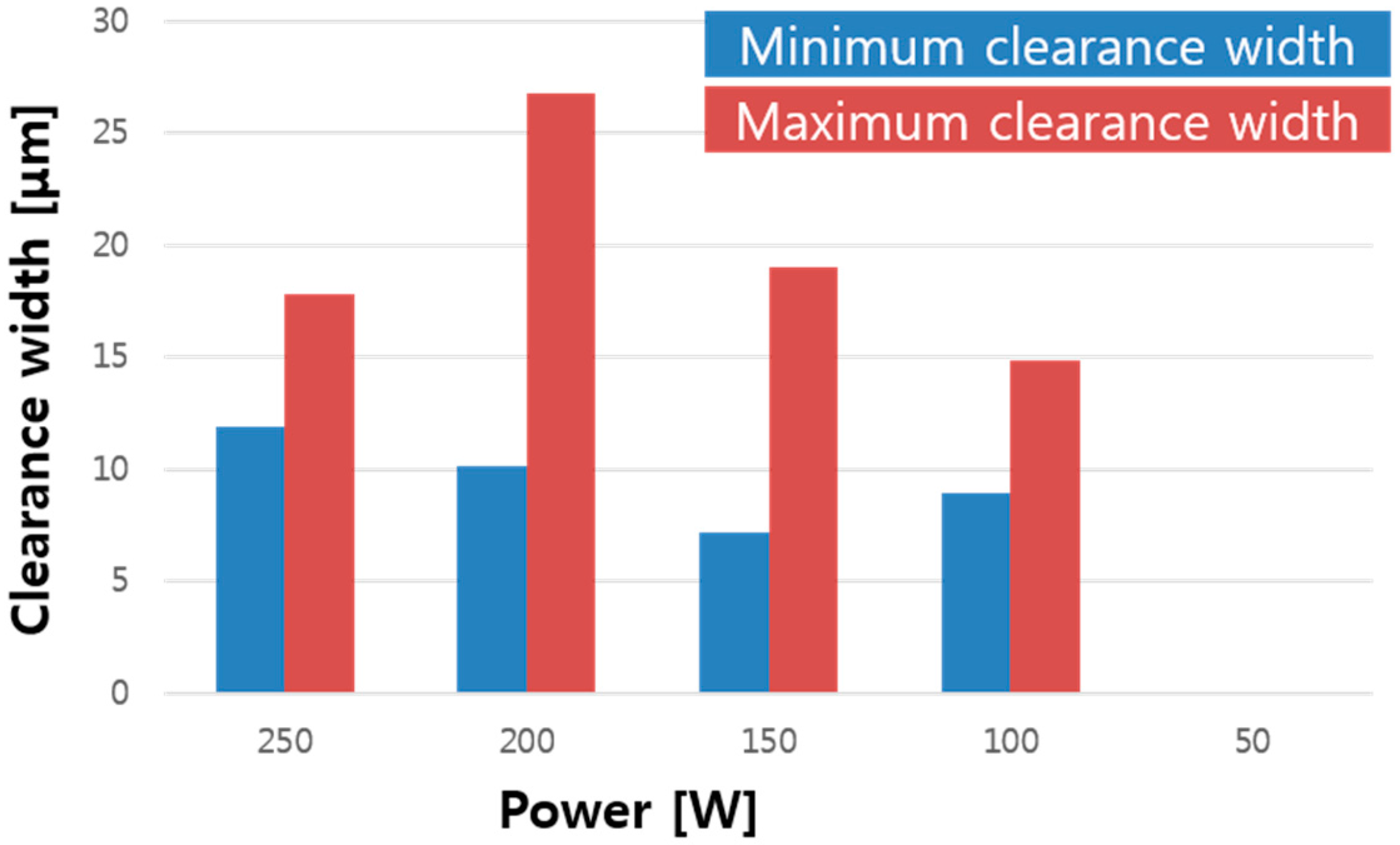
Clearance width was observed previously by Lee et al. [10]. The clearance width () can be derived from the measured top and kerf widths as follows
where is the top width and is the kerf width. The calculated clearance width is shown in Figure 13. All clearance width is less than 20 μm. However, the clearance width interestingly exceeds 20 μm when the laser power is 200 W. The clearance width is very closely related to the above-mentioned material properties. To explain the formation of the clearance width with the above-mentioned material properties, a simplified transient one-dimensional semi-infinite conduction model can be introduced and shown in Figure 14.
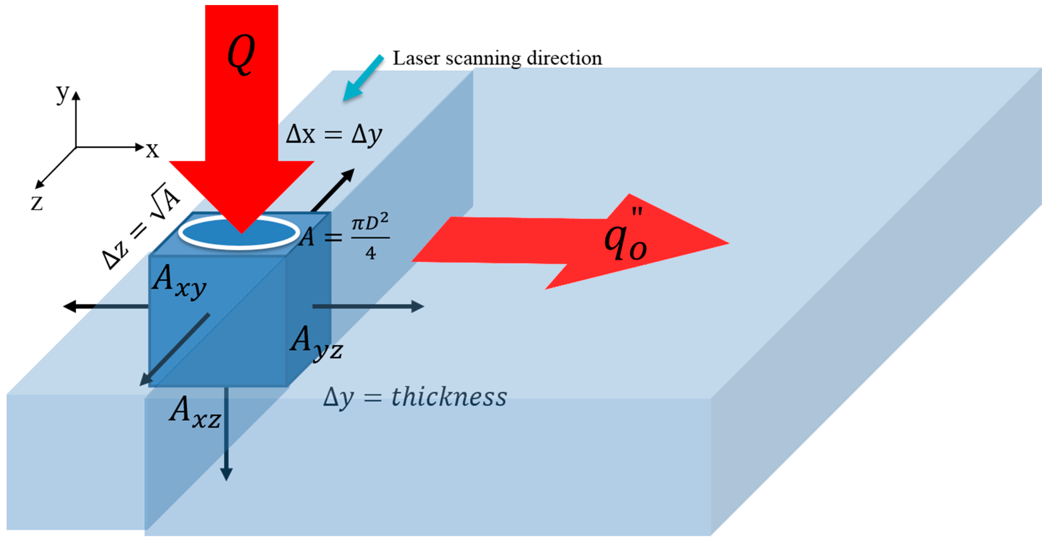
To see the effect of material properties on the clearance width, this model ignores the liquid and vapor phases. A constant surfac heat flux boundary condition is used. In addition, a laser spot area is converted to a rectangular spot size . The transient conduction in a semi-infinite solid model is proposed and written as follows [17]
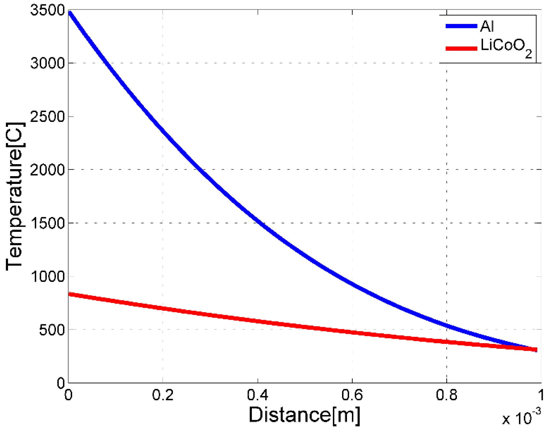
where is the irradiated laser power, is an absorption coefficient, is heat flux (), F is the adjusting factor for numerical solution, is thermal diffucivity (), is thermal conductivity (), and is the complementary error function. Material properties are tabulationed in Table 2. Temperature distribution is obtained when is 250 W, is 500 mm/s, , and . The result at is shown in Figure 9. According to this transient one-dimensional semi-infinite conductinon equation, the temperature of aluminum is 5 times greater than that of LiCoO2. In spite of lower thermal conductivity and the thermal diffusivity of LiCoO2, a higher absorption coefficient has a critical effect on heat transfer and material removal.
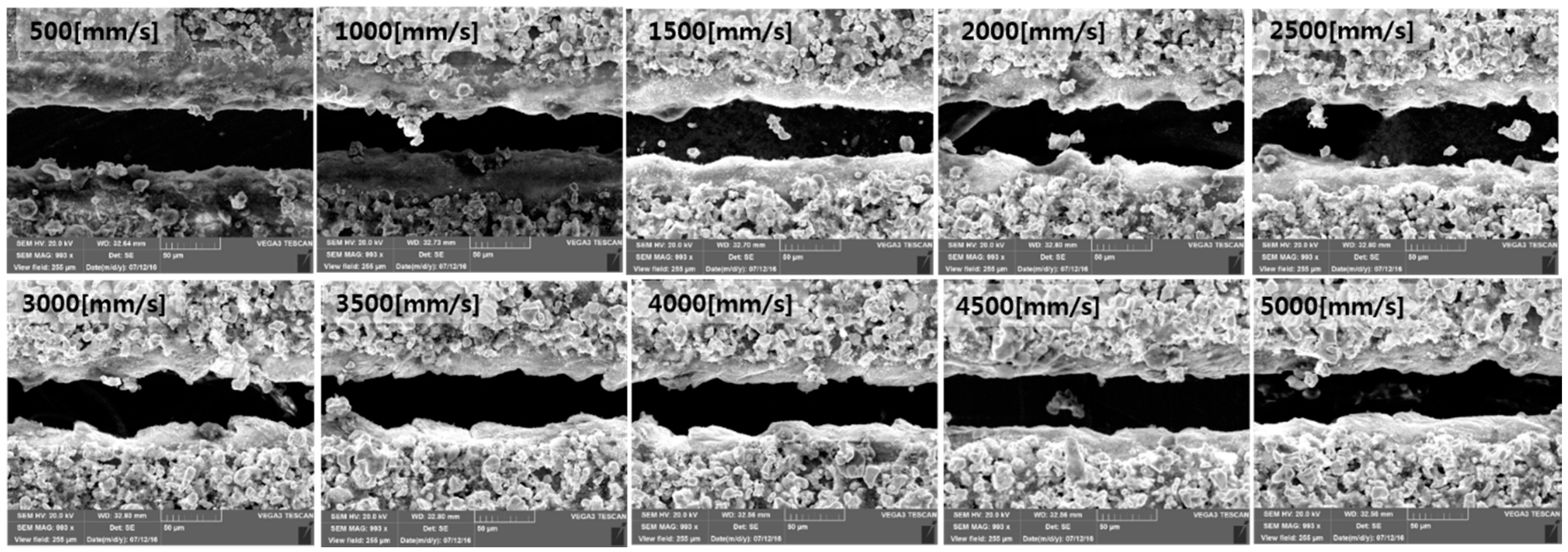
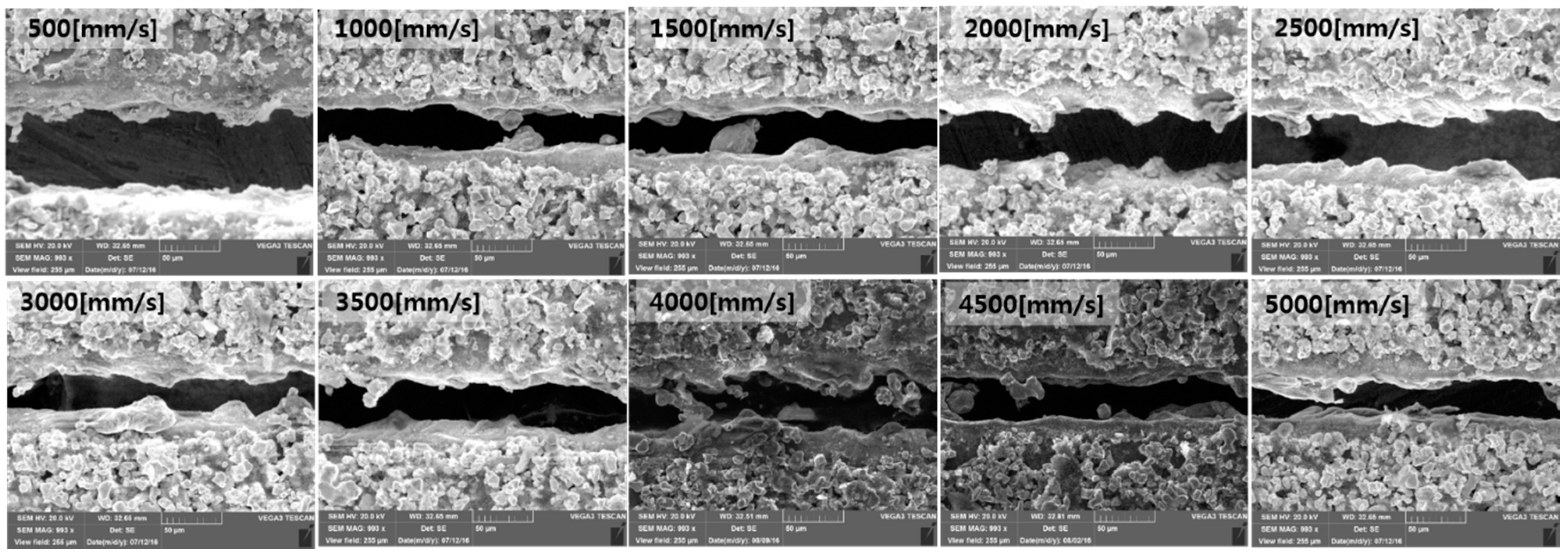
Figure 7 shows the cut surface with the laser power of 250 W. The kerf width is clearly seen under the all the laser scanning speeds. Overall, a clean cut surface is observed, but the a wavy surface at the cut edge of the current collector is observed. This wavy surface can be formed when the liquid aluminum, caused by laser energy absorption, is rapidly re-solidified. Figure 8 and Figure 10 show the SEM images of the laser power of 200 W and 150 W, respectively. These figures show the cut surface, which is very similar to the SEM images of the laser power of 250 W. However, the kerf and clearance widths are relatively narrower, and a more vigorous wavy surface is observed.
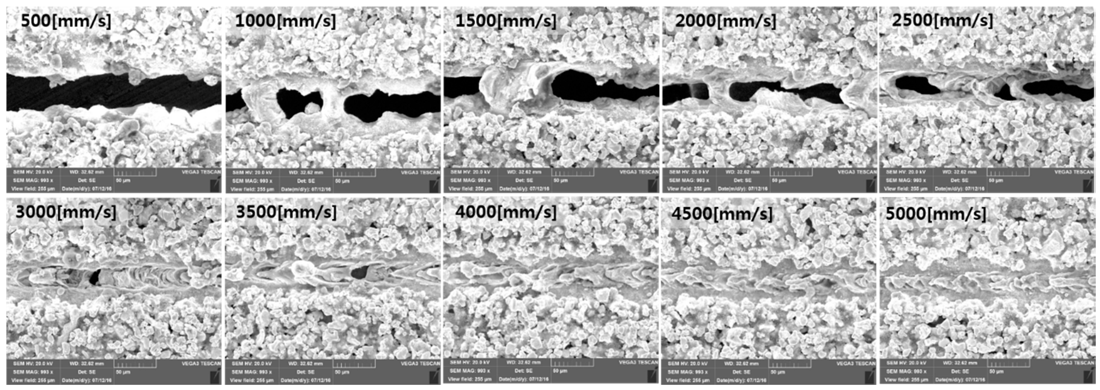
Figure 11 shows the SEM images of the laser power of 100 W. The kerf width decreases rapidly as compared to the cases using other laser parameters, as shown in Figure 6d. In addition, no full penetration is observed between the laser scanning speed of 3000 mm/s and 5000 mm/s. No full peneration shows a characteristic that the active electrode material is fully removed while no current collector is fully removed. Moreover, re-solidification is shown in the region of the current collector. Therefore, under this speed range, the laser energy is not enough to fully penetrate the current collector, but enough to remove the active electrode material. Partial penetratin is observed between 1000 mm/s and 2500 mm/s. In this partial penetration, dross is bonded weakly so that this speed range is the transient laser scanning speed from no penetration cutting to full penetration cutting. Cut images with the laser power of 50 W are shown in Figure 6e and Figure 12. Only active electrode material is partially removed when the laser scanning speed is bewteen 500 mm/s and 2000 mm/s. The top width observed is of the same order of magnitude as the laser spot size, or less than the laser spot size.
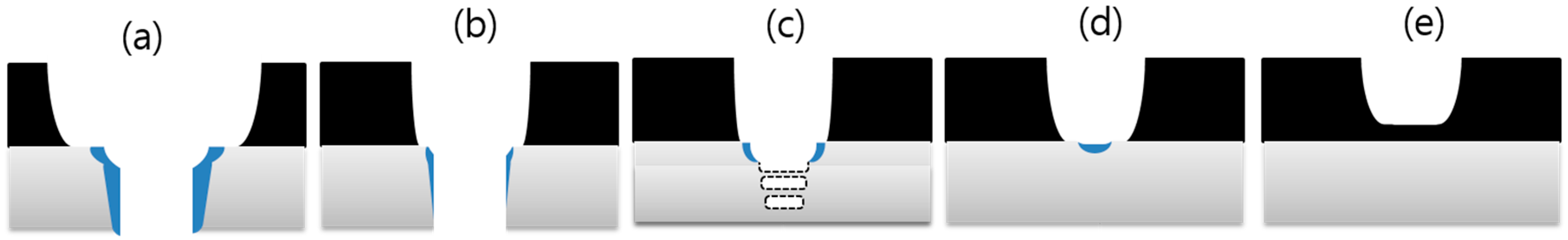
According to the laser cutting characteristics observed in Figure 7, Figure 8, Figure 9, Figure 10, Figure 11 and Figure 12, five types of cross-section can be catergorized. This categorization is shown in Figure 15. Figure 15a,b shows the cross-section where the full penetration of both the active electrode material and current collector is obtained. The required volume energy for the full penetrartion is more than . It is common that the volume energy is enough to penetrate the current collector. However, since the amount of heat energy transfered in the transverse direction is different, a wider top width and a relatively narrower top width are observed, as shown in Figure 15a,b, respectively. Difference in the amount of heat transfer caused by differnet material properties is observed also with the one dimensional semi-finite transient conduction model, as shown in Figure 14. Figure 15c shows the cross-section where the threshold volume energy, which is between , of laser cutting is observed. This cross-section indicates that the given laser energy is not enough to cut the current collector, but enough to remove active elctrode materials. Especially, the partial penetration and re-solidified dross may be created in this cross-sectional geometry. The cross-section where the partial penetration and shallow molten zone exists is shown in Figure 15d. The volume energy is , and it is not enough to evaporate, but is enough to melt the current collector. In addition, it is the active electrode material that can be removed by this volume energy. On the other hand, the volume energy between removes only the active electrode material. This volume energy overlaps the laser volume energy resulting in Figure 15c,d, since it takes into consideration of laser scanning speed instead of laser power, which is the major parameter to affect physical phenomena during laser-material interaction.
4. Conclusions
During lithium-ion manufacturing processes, inefficient conventional cutting technology has been replaced by laser processing since it has many advantages such as a clean cutting edge, less deformation, applicability to almost all materials, possibility of precision processing, and an easy transition of cutting path. Since no clear definition of cutting widths has been presented and there is lack of knowledge to understand the effect of laser parameters on cutting widths in a few previous studies, this study examines the surface morphology of cathode cut by a laser with defining meaningful cutting widths, such as top width, melting width, and kerf width, to investigate the physical phenomena during laser cutting of cathodes. When the volume energy is less than , no active electrode material is removed. When the laser power is greater or equal to 100 W, both the top and melting widths are clearly observed. The laser power of 50 W can selectively ablate the active electrode material with the material removal rate of 32.14–55.71 . The threshold volume energy to fully penetrate the 50 μm-thick current collector is between . All clearance widths are less than 20 μm, while the clearance width interestingly exceeds 20 μm when the laser power is 200 W. To explain the formation of clearance widths, one dimensional transient semi-infinite conduction model is proposed. In addition, five types of physical characteristics are defined and discussed with SEM images. Based on this approach, this study proposes the systematic analysis of laser cutting of electrodes for lithium-ion batteries. This method will be applied to the laser cutting of thicker cathodes for high power applications and transferability of this analysis will be tested for the future research.
Acknowledgments
The research described herein was supported by the National Research Foundation of Korea (NRF) grant funded by the Korean government (MSIP; Ministry of Science, ICT & Future Planning) (No. 2017R1C1B507916). This work was also supported by the Hana Technology Co., Ltd, Republic of Korea. The opinions expressed in this paper are those of the authors and do not necessarily reflect the views of the sponsors. The authors appreciate the support from our sponsors.
Author Contributions
D. Lee and S. Ahn worte this paper together.
Conflicts of Interest
The authors declare no conflict of interest.
References
- Alamgir, M.; Sastry, A.M. Efficient Batteries for Transportation Applications; SAE Convergence: Detroit, MI, USA, 2008. [Google Scholar]
- Lee, D.; Patwa, R.; Herfurth, H.; Mazumder, J. Computational and experimental studies of laser cutting of the current collectors for lithium-ion batteries. J. Power Sources 2012, 210, 327–338. [Google Scholar] [CrossRef]
- Nitta, N.; Wu, F.; Lee, J.T.; Yushin, G. Li-ion battery materials: Present and future. Mater. Today 2015, 18, 252–264. [Google Scholar] [CrossRef]
- Lee, D. Experimental Investigation of Laser Spot Welding of Ni and Au-Sn-Ni Alloy. J. Weld. Join. 2017, 35, 1–5. [Google Scholar] [CrossRef]
- Lee, D.; Mazumder, J. Effects of laser beam spatial distribution on laser-material interaction. J. Laser Appl. 2016, 28, 032003. [Google Scholar] [CrossRef]
- Steen, W.M.; Mazumder, J. Laser Material Processing, 4th ed.; Springer: London, UK, 2010. [Google Scholar]
- Kannatey-Asibu, E., Jr. Principles of Laser Materials Processing; Wiley: Hoboken, NJ, USA, 2009. [Google Scholar]
- Lee, D.; Cho, J.; Kim, C.H.; Lee, S.H. Application of Laser Spot Cutting on Spring Contact Probe for Semiconductor Package Inspection. Opt. Laser Technol. 2017, 97, 90–96. [Google Scholar] [CrossRef]
- Lee, D.; Mazumder, J. Effects of momentum transfer on sizing of current collectors for lithium-ion batteries during laser cutting. Opt. Laser Technol. 2017, in press. [Google Scholar]
- Lee, D.; Patwa, R.; Herfurth, H.; Mazumder, J. High speed remote laser cutting of electrodes for lithium-ion batteries: Anode. J. Power Sources 2013, 240, 368–380. [Google Scholar] [CrossRef]
- Lee, D.; Patwa, R.; Herfurth, H.; Mazumder, J. Three dimensional simulation of high speed remote laser cutting of cathode for lithium-ion batteries. J. Laser Appl. 2016, 28, 032010. [Google Scholar] [CrossRef]
- Lee, D.; Patwa, R.; Herfurth, H.; Mazumder, J. Parameter optimization for high speed remote laser cutting of electrodes for lithium-ion batteries. J. Laser Appl. 2016, 28, 022006. [Google Scholar] [CrossRef]
- Lutey, A.H.A.; Fortunato, A.; Ascari, A.; Carmignato, S.; Leone, C. Laser cutting of lithium iron phosphate battery electrodes: Characterization of process efficiency and quality. Opt. Laser Technol. 2015, 65, 164–174. [Google Scholar] [CrossRef]
- Lutey, A.H.A.; Fortunato, A.; Carmignato, S.; Fiorini, M. High speed pulsed laser cutting of LiCoO2 Li-ion battery electrodes. Opt. Laser Technol. 2017, 94, 90–96. [Google Scholar] [CrossRef]
- Schmieder, B. Analytical model of the laser ablation mechanism of lithium-ion battery coatings. Proc. SPIE 2015, 9351, 13. [Google Scholar] [CrossRef]
- Yilbaş, B.S.; Yilbaş, Z. Effects of plasma on CO2 laser cutting quality. Opt. Lasers Eng. 1988, 9, 1–12. [Google Scholar] [CrossRef]
- Bergman, T.L.; Lavine, A.S.; Incropera, F.P.; DeWitt, D.P. Fundamentals of Heat and Mass Transfer, 7th ed.; Wiley: Hoboken, NJ, USA, 2011. [Google Scholar]
Figure 1.
Cathode sample and Experimental set-up.
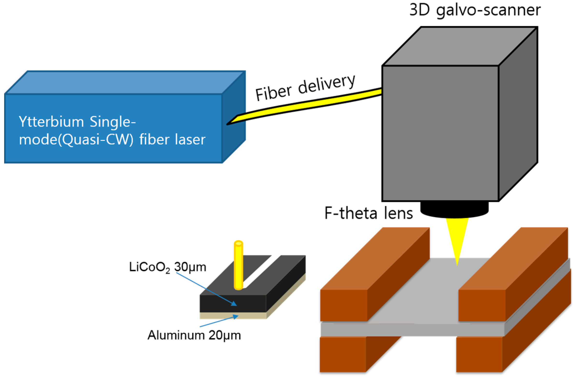
Figure 2.
Definition of measured width.
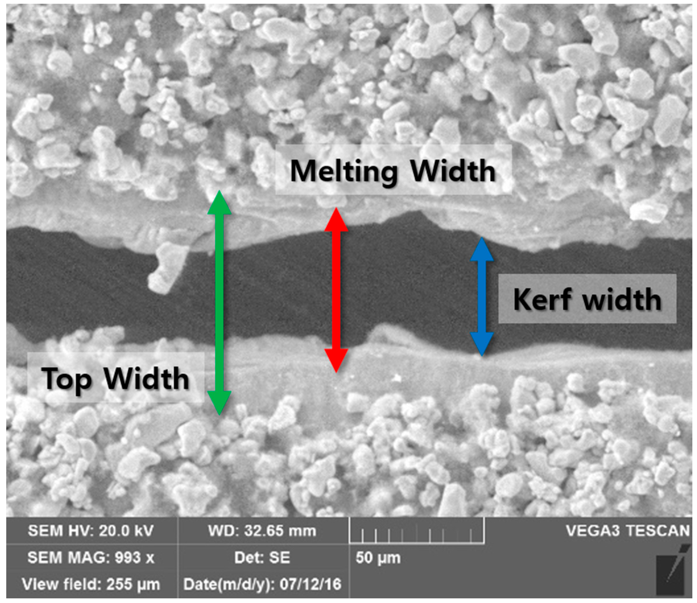
Figure 3.
(a) Top width VS. Scanning speed; (b) Volume energy.

Figure 4.
(a) Melting width VS. Scanning speed; (b) Volume energy.
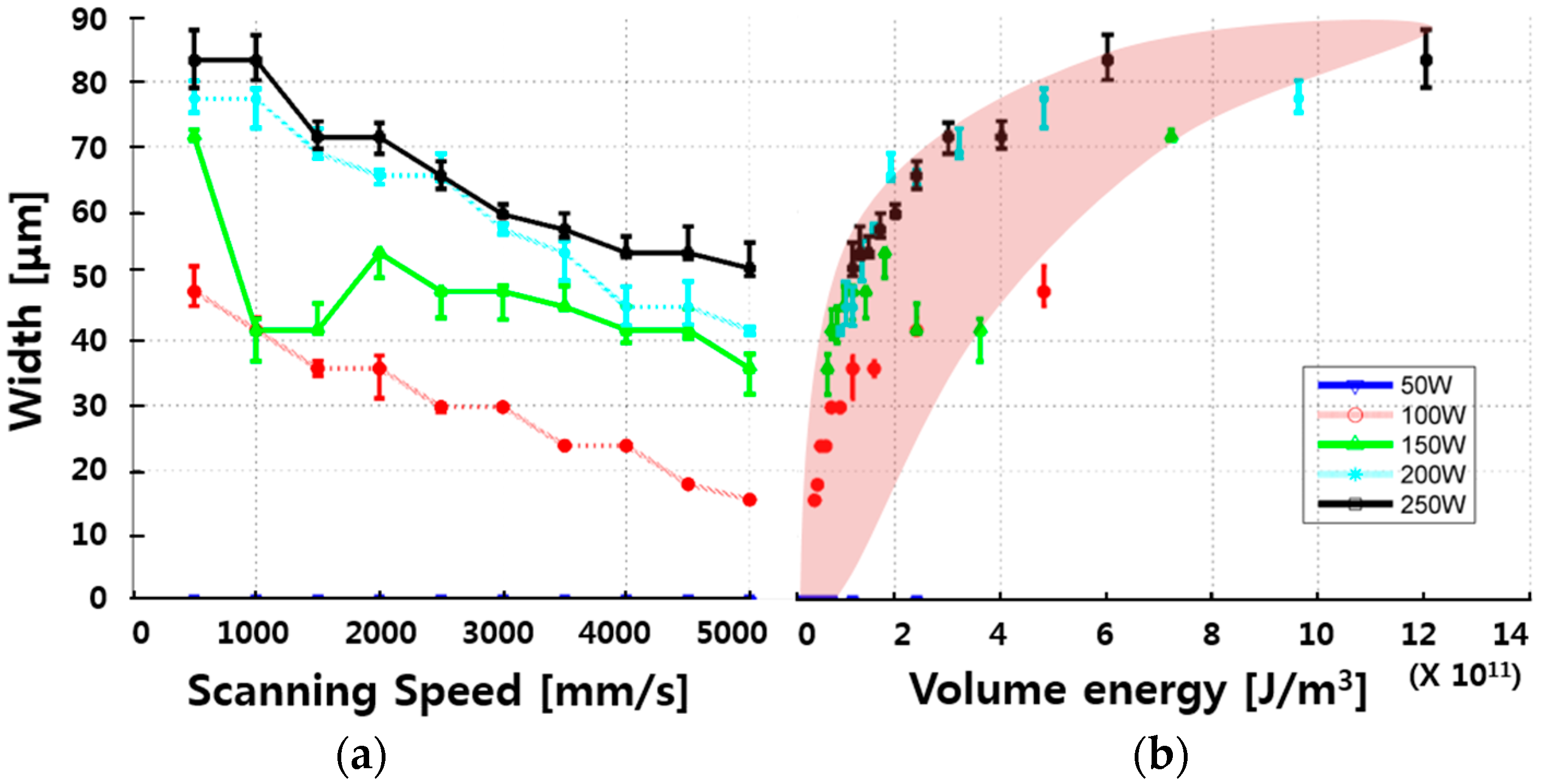
Figure 5.
(a) Kerf width VS. Scanning speed; (b) Volume energy.

Figure 6.
Width variation VS. Volume energy when laser power (a) 250 W; (b) 200 W; (c) 150 W; (d) 100 W; and, (e) 50 W.
Figure 6.
Width variation VS. Volume energy when laser power (a) 250 W; (b) 200 W; (c) 150 W; (d) 100 W; and, (e) 50 W.

Figure 7.
Clearance width by laser power.
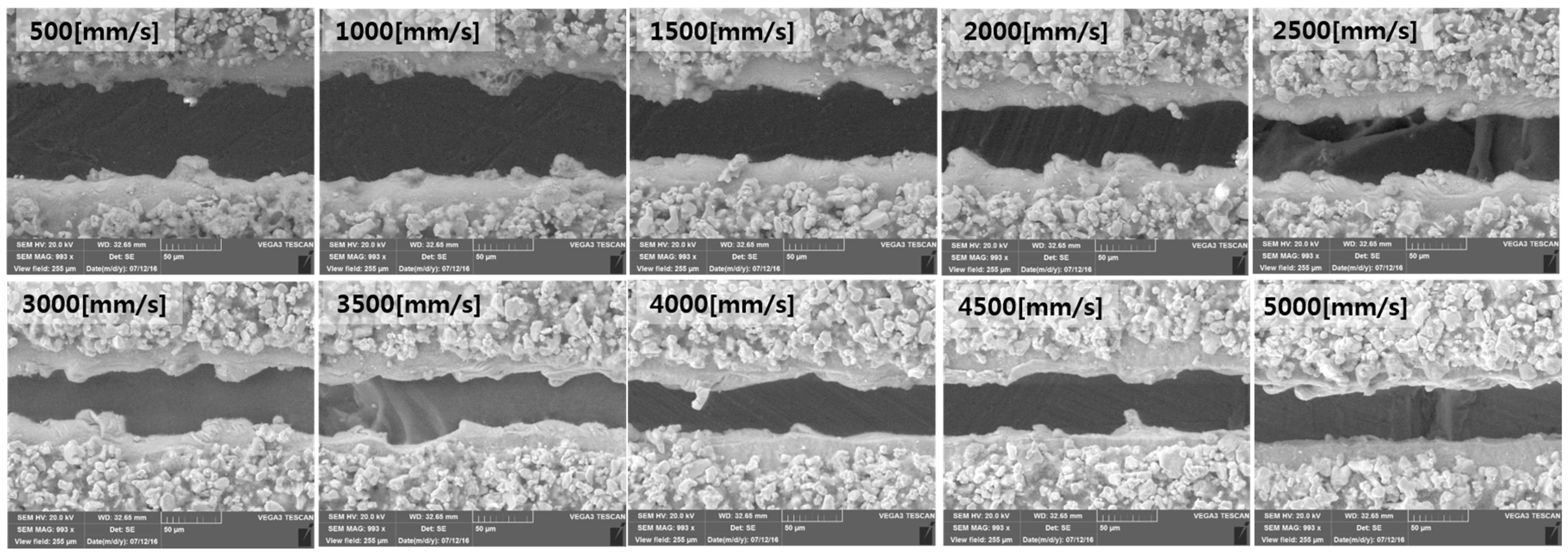
Figure 8.
One-dimensional semi-infinite conduction model.

Figure 9.
Scanning Electron Microscope (SEM) image with a laser power of 250 W.

Figure 10.
SEM image with a laser power of 200 W.

Figure 11.
Result of one-dimensional semi-infinite conduction model.

Figure 12.
SEM image with a laser power of 150 W.
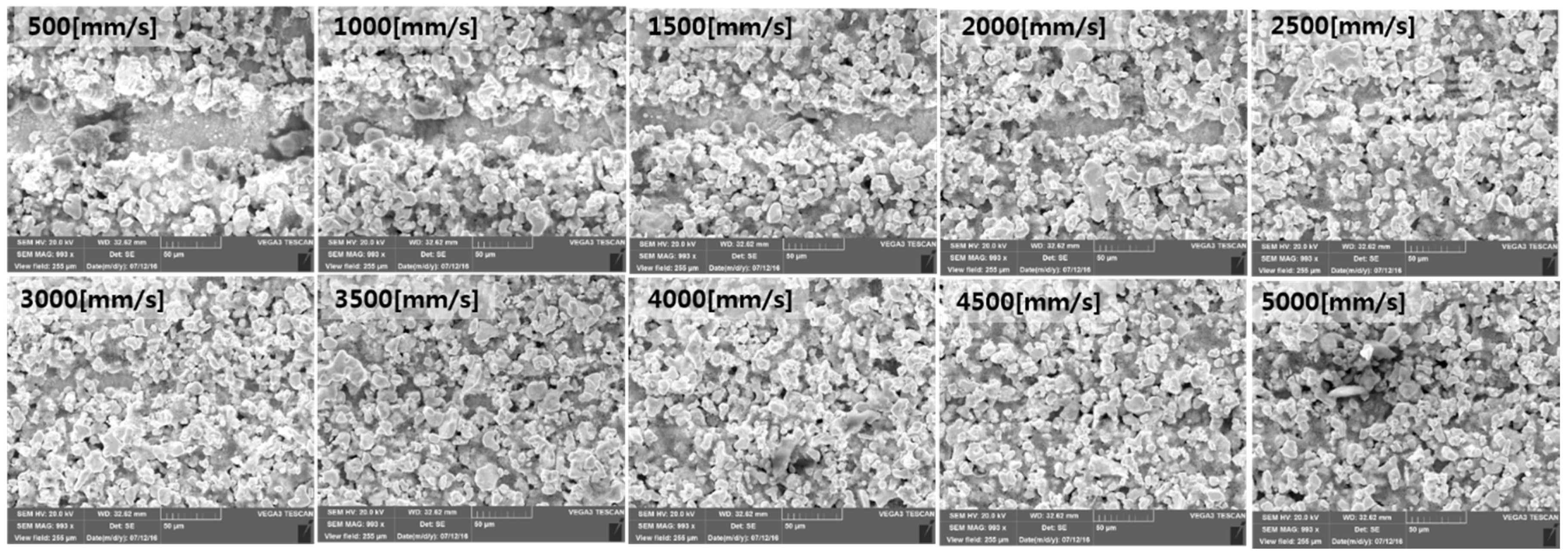
Figure 13.
SEM image with a laser power of 100 W.

Figure 14.
SEM image with a laser power of 50 W.

Figure 15.
Five types of physical characteristics with cross sectional view. (a) full penetration of electrodes; (b) full penetration of electrodes with narrower top width; (c) partial penetration of electrodes; (d) partial penetration and shallow molten zone; (e) partial removal of active electrode material.

Table 1.
Cathode manufacturing parameters.
| Category | Cathode |
|---|---|
| Structure | One-side sandwich |
| Active electrode Material | LiCoO2 |
| Active electrode Thickness | 30 [μm] |
| Binder | Polyvinylidene fluoride |
| Conducting agent | SuperC65 |
| Ratio | 90:5:5 wt % |
| Solution | N-Methyl-2pyrrolidone |
| Current collector Material | Aluminum |
| Current collector Thickness | 20 [μm] |
Table 2.
Material properties of cathode materials.
| Material Properties | LiCoO2 | Aluminum |
|---|---|---|
| Solid Thermal conductivity [] | 46.6 | 237.7 |
| Solid Thermal diffusivity [] | 2.295−5 | 9.790−5 |
| Absorption coefficient on flat surface | 0.17 | 0.07 |
| Thickness [] | 30 | 20 |
| Melting temperature [K] | 1130 | 933.47 |
| Boiling temperature [K] | 2054.29 | 2792 |
© 2017 by the authors. Licensee MDPI, Basel, Switzerland. This article is an open access article distributed under the terms and conditions of the Creative Commons Attribution (CC BY) license (http://creativecommons.org/licenses/by/4.0/).
Share and Cite
MDPI and ACS Style
Lee, D.; Ahn, S. Investigation of Laser Cutting Width of LiCoO2 Coated Aluminum for Lithium-Ion Batteries. Appl. Sci. 2017, 7, 914. https://doi.org/10.3390/app7090914
AMA Style
Lee D, Ahn S. Investigation of Laser Cutting Width of LiCoO2 Coated Aluminum for Lithium-Ion Batteries. Applied Sciences. 2017; 7(9):914. https://doi.org/10.3390/app7090914
Chicago/Turabian StyleLee, Dongkyoung, and Sanghoon Ahn. 2017. "Investigation of Laser Cutting Width of LiCoO2 Coated Aluminum for Lithium-Ion Batteries" Applied Sciences 7, no. 9: 914. https://doi.org/10.3390/app7090914
Note that from the first issue of 2016, this journal uses article numbers instead of page numbers. See further details here.