Seismic Damage Investigation of Spatial Frames with Steel Beams Connected to L-Shaped Concrete-Filled Steel Tubular (CFST) Columns


1
School of Urban Construction, Yangtze University, Jingzhou 434023, China
2
School of Environment and Civil Engineering, Dongguan University of Technology, Dongguan, Guangdong 523808, China
3
School of Civil Engineering, Southwest Jiaotong University, Chengdu 610031, China
*
Authors to whom correspondence should be addressed.
Appl. Sci. 2018, 8(10), 1713; https://doi.org/10.3390/app8101713
Submission received: 12 August 2018
/
Revised: 17 September 2018
/
Accepted: 18 September 2018
/
Published: 20 September 2018
(This article belongs to the Special Issue Structural Damage Detection and Health Monitoring)
Abstract
:Currently, the frame structures with special-shaped concrete-filled steel tubular columns have been widely used in super high-rise buildings. Those structural members can be used to improve architectural space. To investigate the seismic behavior of spatial composite frames that were constructed by connecting steel beams to L-shaped concrete-filled steel tubular (CFST) columns, a finite element analysis (FEA) model using commercial finite element software ABAQUS was proposed to simulate the behavior of the composite spatial frames under a static axial load on columns and a fully-reversed lateral cyclic load applied to frames in this paper. Several nonlinear factors, including geometry and material properties, were taken into account in this FEA model. Four spatial specimens were designed, and the corresponding experiments were conducted to verify the proposed FEA model. Each testing specimen was two-story structure consisting of eight single span steel beams and four L-shaped CFST columns. The test results showed that the proposed FEA model in this paper could evaluate the behavior of the composite spatial frames accurately. Based on the results of the nonlinear analysis, the stress developing progress of columns is investigated. The load transferring mechanism and failure mechanism are also determined. The results are discussed and conclusions about the behavior of those spatial frame structures are presented.
1. Introduction
A concrete-filled steel tubular (CFST) frame is composed of CFST columns and steel or reinforced concrete beams [1,2]. Nowadays, this CFST frame structure has been widely used in practical construction projects, due to remarkable features, such as high bearing capacity [3,4,5,6], large stiffness [7,8,9], and superior anti-seismic performance [10,11,12,13,14]. Additionally, some special shaped concrete-filled steel tubular components, such as L-shaped columns, can be utilized to enhance the internal space and thus beneficial for the placement of furniture by avoiding undesired configuration of the edges and corners in structures [15,16,17,18,19,20,21].
Currently, some scholars have proposed a new model that is suitable for the single specimen of concrete-filled steel tube by considering the material constitutive model. Patel et al. [22,23,24] developed a new numerical model to predict the cyclic characteristics of CFST columns, which was under cyclic loading or eccentric loading. Some theoretical and experimental investigations on the seismic behavior of steel beam connected to CFST column plane frames have been explored and reported in the literatures. Herrera et al. [25] used the finite element analysis program, named as DRAIN-2DX, to establish a full-scale model of a four-story and five-bay frame made of wide flange H-shaped beams connecting to square CFST columns. Dasgupta et al. [26] carried out the test for a three-story and three-bay planar frame with CFST column connecting to steel beam. Liu and Li [27] conducted a test to demonstrate that the yield load, ultimate load-carrying capacity, and ductility of the frame that was filled with masonry wall were greatly improved, as compared to those in the pure frame structure. Han [28] built a finite element analysis (FEA) to study the behavior of the composite frame, and the results obtained from the FEA model were validated against the test results. Li et al. [29] investigated the seismic performance of CFST frame structure under the constant axial load and cyclic horizontal load. Wang et al. [30] analyzed the mechanism of composite frames with steel beams connecting to concrete-filled square steel tubular columns by using FEA modeling and proposed the simplified hysteretic lateral load-displacement models. Wang et al. [31] established the nonlinear finite element model of squared CFST frame to study the influence of the slenderness ratio. Hu et al. [32] and Park et al. [33] developed a design methodology for moment resisting frame structures with tubular CFST columns and conducted a nonlinear pushover analysis on the numerical frame models. Wang [34,35] conducted an experimental study and nonlinear finite element analysis to study the seismic behavior of concrete-filled square steel tubular frames. Zhou et al. [36] experimentally investigated the behavior of SCFST frames that were subjected to constant axial load and cyclic lateral load. Xu [37] and Wang [38] carried out experimental and theoretical studies on the seismic performance of three-story and two-story CFST structures that are based on damage assessment.
In addition, structural damage detection [39,40,41] and health monitoring methods [42,43,44,45,46,47,48,49] have been developed to monitor the damage status and health of structures in real time. On the other hand, experimental and numerical studies have also been performed to predict the structural behavior and failure mode subjected to unexpected loads like impacts, explosions, and other high dynamic loads [50,51,52]. Since the slips existed along the interface between the steel and concrete, some scholars conducted experimental investigations on concrete structure under cyclic loading and studied the bond-slip and debonding behavior between the steel and the concrete while using piezoelectric technologies [53,54,55,56,57,58].
It can be summarized from the reported literatures that the existing research mainly focuses on the frame structure or a single joint with regular symmetric columns, and the bidirectional stiffness is basically consistent when resisting seismic loads. However, the study of the spatial frame structure with special-shaped concrete-filled steel tubular columns has not been reported to the best knowledge of the authors. The spatial frame is more integral than the planar frame because of the addition of the floor diaphragms. The spatial frame structure of the special-shaped concrete-filled steel tubular column is more complicated than the frame structure of the regular column since the space utilization of the structure is enhanced. Moreover, the L-shaped concrete-filled steel tubular column is an asymmetrical structure, which will be subjected to torsion under seismic load at random directions. It is very complicated to define the interface and contact model in simulation. In the study of seismic problems, the nodes and bottoms of column of spatial frame structure with special-shaped concrete-filled steel tubular columns are weak parts and they are more susceptible to damage.
The experimental investigation of seismic behavior of composite spatial frames with steel beams connecting to L-shaped CFST columns were conducted in the previous study by authors [59]. This study aims at extending the understanding of seismic damage of those composite structures by using nonlinear finite element analysis. Those experimental test models were adopted as physical model for the proposed numerical analysis. In this paper, a numerical model was built to simulate the behavior of composite spatial frames when applying a constant axial load on columns and fully-reversed lateral cyclic load on frames. Finite element analysis software ABAQUS was employed in this study. Six main components were considered in this analysis, i.e., the core concrete of L-shaped steel tubular columns, steel tubes, the interfacial contact between the concrete and steel tubes, steel beams and attachments characteristic between beams and columns, and the connection details between the columns and L-shaped inner diaphragm. A series of new experimental data was obtained by testing the behavior of the composite spatial frames under specific loads. This experimental test results were used to validate the numerical simulation model proposed in this paper. In the experimental study, each specimen consists of two-story single span steel beam (eight in total) and four L-shaped CFST columns. The effect of axial compressive load ratio and loading direction on the mechanical behavior of composite frames were experimentally investigated. The accuracy of the FEA model was estimated by comparing the numerical with the experimental results. It was found that the results from FEA model, which used the constitutive model of steel and core concrete proposed in this study conformed to those that were obtained by the experimental tests.
2. Finite Element Models
2.1. General Description
To accurately simulate the behavior of frames with L-shaped CFST columns connecting to steel beams, the main factors of the frame models, including the core concrete of L-shape CFST columns, the steel tube and its interfacial contact with concrete, the columns and their connection with steel beams, and L-shaped inner diaphragm separately, were considered and modeled. Finite element analysis software ABAQUS was adopted in this paper. To study the behavior of the L-shaped CFST frames accurately and reasonably, some key issues that need to be solved are as follows: constitutive relation model of steel and core concrete, element type of steel tube and concrete, mesh size, interface and contact model between steel tube and core concrete, boundary conditions, loading criterion, convergence criterion, and the solution.
The span of frames was 1.8 m, the story height of frames was 1.2 m, the width of the frame columns section was 160 mm and the thickness of the steel tube was 4 mm. The size of H-type steel beam was 120 mm × 80 mm × 4mm × 4 mm and the thickness of floor slab distributed with Φ10@100 steel meshes was 50 mm.
2.2. Material Constitutive Equations
2.2.1. Material Modeling of Steel
An elastic-plastic model with Von-Mises yield criteria and Prandtl–Reuss flow rule were utilized to simulate the plastic behavior of the steel. The stress-strain relation of steel that was used in the CFST structures can be divided into five stages [60,61]: the elastic stage (oa), the elastic plastic stage (ab), the plastic section stage (bc), the hardening stage (cd), and the secondary plastic flow section stage (de), as shown Figure 1. The *PLASTIC option in finite element software allows to use multiple linear or bilinear stress-strain curves. This model was used for defining steel and steel beams. The Poisson’s ratio (νs) was equal to 0.25. The isotropic yield of the steel material and the model steel for steel assumes associated plastic flow were defined by Mises. The *INITIAL CONDITIONS option in finite element software provides a model that considers the residual stress of the material, and thus we can define TYPE as stress.
2.2.2. Material Modeling of Core Concrete
The complex, nonlinear material behavior of concrete was described by the elasto-plastic damage model—concrete damaged plasticity, which was developed by Lubliner et al. [62] and elaborated by Lee and Fenves [63]. This model assumes non-associated potential plastic-flow where the flow potential is defined by the Drucker-Prager hyperbolic function and the yield function. This assumption provides a realistic simulation of the concrete in compression, because a major point of departure of concrete behavior from metal is that it cracks in a quasi-brittle manner under relatively low stress. The tensile behavior is defined by a crack detection surface, which forms part of the yield function. On reaching the yield surface, a crack perpendicular to the maximum principal tensile stress is assumed to have formed and the stiffness is modified according to representing the behavior of such a crack.
The damage plastic model with the modified Drucker–Prager yielding criterion and the non-associated flow rule that was defined in ABAQUS were used for concrete in this analytical model. The model allows inputting a multi-linear uniaxial compression stress-strain curve. In this paper, the authors proposed a practical equivalent uniaxial stress-strain constitutive model of the L-shape concrete-filled steel tubular structure, which had been verified in L-shaped concrete-filled steel tubular columns [64,65]. The core concrete equivalent stress-strain curve was shown in Figure 2. The compressive behavior of the core concrete could be described, as follows:
where: x is the normalized strain, , y is the normalized stress, , σ0 is the concrete compressive stress, , ε0 is concrete strain at the concrete compressive stress, , η, β0, and ξ are coefficients, and , , .
2.3. Finite Element Type and Mesh
2.3.1. Finite Element Type
The L-shaped CFST column frames mainly consisted of L-shaped concrete-filled steel tubular columns, steel beams and composite slab. In finite element analysis which was based on ABAQUS, four-node doubly curved shell and complete integral format shell elements (S4) (which was proved to meet the yield criterion of Mises by Varma [66]) were applied to steel tubes and the steel beam. Meanwhile, eight-node linear brick and reduced integral solid element (C3D8R) (which was proved to meet the yield criterion of Drucker-Prager by Varma [67]) was used for core concrete, composite slab, L-shaped inner diaphragm, horizontal loading plate, and rigid plates at the end of the CFST columns.
A linear element was adopted in the element model, and the mesh sensitivity experiment was carried out to analyze the convergence of the grid and the accuracy of the calculation computational results. Under the circumstances above, the specific approach was given, as follows: First, a more reasonable initial analysis of grid division was performed in order to guarantee the accuracy. Second, three-dimensional measurement of the grid should be similar, if not, doubled measurement of grid and reanalysis until the difference between two results was less than 1%. Otherwise, the refinement of grid measurement should be continued until the calculated computation results of the partitioning were approximately equal.
2.3.2. Finite Element Mesh
To find a suitable mesh method and to reduce computation cost, various element sizes were used to obtain accurate simulation results. Based on the comparative results, the ratio of length, width and height was accurate enough for solid structure as 1:1:2. Additionally, for shell element, the effect was satisfactory when length to width ratio was 1:2. Mapping method of Mesh was used in the model analysis, typical meshes of the L-shaped CFST frames were depicted in Figure 3.
2.3.3. Interface and Contact Processing
The interface element that was provided by ABAQUS was used to simulate the matching contact surfaces between steel tubular and concrete. Simultaneously, to consider the normal and tangential contact between two surfaces, interfacial friction was modeled by using the Coulomb friction model, of which the friction coefficient was set as from 0.2 to 0.6 [68]. In this paper, the coefficient of friction was selected as 0.25, which was also suggested in the research by Schneider [69], Susantha et al. [70], Hu et al. [71], and Tao et al. [72]. The contact surface model can simulate infinitesimal sliding and friction between the concrete and the steel tube, in which the concrete and the steel tube were allowed to separate, but not to penetrate, each other [73,74].
Considering that steel tubes being modeled as shell elements, the rigid plates at the end of L-shaped CFST columns and L-shaped inner diaphragm were solid elements and the connections between them were welded, the interface contact relationships were defined between them as the Shell-to-Solid Coupling. Since the H-shaped steel beam was welded to the L-shaped CFST columns, the *TIE constraint relationship was used to simulate the welding. The hard contact was applied between rigid plate, L-shaped inner diaphragm and core concrete. In the experiment, all composite slabs were in the elastic stage, and no slide appeared between the composite slabs and the steel beams. Therefore, we used the approach of nodal coupling to simulate the contact between the slabs and steel beams.
2.3.4. Boundary Conditions and Load Application
The bottom surfaces of CFST columns were fixed, i.e., all of the degrees-of-freedom were zero (UR1 = UR2 = UR3 = U1 = U2 = U3 = 0). Axial static load was applied on the top surface of CFST columns by using the load function in ABAQUS software. Similarly, the horizontal and cyclical load was achieved by a specific boundary condition in term of displacement, to excite the steel beam. Several techniques, such as static and general nonlinear arithmetic, were used in the load step and displacement step. The axial load and the horizontal cyclic load were transferred to the test specimens by elastic rigid plates with the modulus of elasticity of 2.0 × 10¹⁰ MPa and a Poisson’s ratio of 0.0001.
3. Frame Tests
A series of tests on composite frames with steel beam to CFST columns were conducted by the authors [59] and the test results were used to verify the FEA model that is presented in the paper.
3.1. Design of Experimental Specimens
Four spatial specimens of the steel beam connecting to L-shaped CFST column frames were constructed in this study and consisted of two-story and single-span. The specimens were named as CF1, CF2, CF3, and CF4, respectively. Table 1 shows the design parameters of the test models. The results of the steel used in this study were shown in Table 2. The compressive strength of concrete materials was determined by the cube compressive test. The average compressive strength of concrete materials in this study was 36.8 MPa.
3.2. Test Setup and Loading System
The test setup and instrumentation layout for frame specimens with L-shaped CFST columns were shown in Figure 4 and Figure 5.
In the experiment, the vertical load was applied by the hydraulic jack according to the axial compressive load ratio, and the hydraulic jack was attached to the slip support to ensure the lateral motion of the frame. Then, the MTS actuator was used to apply a lateral load to the frames, meanwhile, the vertical load value was kept as constant. However, the yielding load (Py) of the structure cannot be determined directly. To solve it, the method of displacement-controlled loading was utilized in this study. The lateral cyclic loading protocol on frames was selected according to ATC-24 [75]. The loading history that is provided by Han et al. [76] was used for cyclic tests. The total horizontal displacement applied at the loading point on the frames, the corresponding displacement increments and the numbers of cycles at each displacement level were shown in Table 3. The displacement was applied until the experimental specimens failed and the loading was then stopped.
3.3. Test Results and Discussion
3.3.1. Failure Modes
As expected, it was found that all of the test specimens followed similar failure modes, which complied with the characteristics of the design principle of the strong-column-weak-beam. As the displacement and number of cycles increased, the flanges at the end of the first story steel beams began to buckle firstly, and the stress gradually reached the yield strength and formed plastic hinge. Then, the flanges at the end of the second story steel beam also started to buckle and the plastic hinge was formed. Then, the exterior sides of the steel column base started to buckle and the confining force offered by the steel tube to the core concrete decreased gradually. Finally, the concrete of buckled areas was crushed and plastic hinge at the bottom of columns appeared until frames were total collapsed. The typical failure mode of test frame CF2 after testing was shown in Figure 6. In addition, after the experiment, there was no local buckling in the steel tube of the beam-column connections. After removing the steel tube, no concrete cracking was detected within beam-column joints, which demonstrated that the beam-column joints satisfied the requirements of bearing capacity in the seismic design.
3.3.2. Lateral Load (P) versus Lateral Displacement (∆)
Under various cyclic horizontal loads, hysteretic curves of the lateral load versus the lateral total displacement of the frame are shown in Figure 7.
According to the curves of lateral load versus the lateral displacement, the hysteretic loops of all the test frames are similar as plump spindles, which indicate that L-shaped concrete-filled steel tubular frames exhibit good plastic deformation capacity and energy dissipation capacity, as shown in [77]. Therefore, it can be concluded that the composite frames that are described in the paper showed good seismic performance. It is also shown that the influence of both the axial compressive load level (N) and loading direction (n) on the ultimate lateral load and the ductility of the global composite frame structures were significant. The hysteretic loop areas of CF1, CF2, CF3, and CF4 are similar and the failure mode is in line with the mode of seismic failure shown in [78,79].
The skeleton curves of lateral load versus lateral displacement are shown in Figure 8. As depicted in the Figure 8, the positive and negative loads and the corresponding displacements of the test frame were not completely symmetrical, the phenomenon of which might be attributed to the follow reasons: (1) the Bausinger effect; (2) the unsymmetry of special-shaped columns; (3) the effect of floor slab; and, (4) the methods applied testing. Meanwhile, with the increase of axial compressive load ratio, the ultimate horizontal load-carrying capacity of tested frames changed slightly. However, the decreased segment of skeleton curves was obvious. This suggested that the displacement ductility of frame structure was reduced by increasing the axial compressive load ratio. The axial compressive load ratio is an important factor affecting the stiffness of the frame structure. As the axial compression ratio increased, the elastic stiffness increases. For the frame structure that is consistent with the corresponding ground motion direction, the elastic stiffness of the frame structure was enhanced by increasing the axial compressive load ratio. The reason of which is that the axial load increases against the tensile stress generated by the lateral load and the elastic stiffness of the frame structure was enhanced.
4. Verification of the Finite Element Model
The finite element models presented above were used to simulate the behavior of the L-shaped CFST members [80,81]. To validate the accuracy of the numerical simulation model, monotonic lateral load versus displacement curves of composite frames were predicted by the proposed FEM model and they were compared with the experimental envelop curves of the measured the curves of lateral load versus the lateral displacement, as shown in Figure 9. It can be noted that the FEA results showed good agreement with the test results.
Table 4 showed the comparison of final lateral loads of composite frames as measured by the tests and the numerical simulation computation. It was found that the predicted capacity by FEA showed good agreement with those obtained from the tests with average P0max-to-Pexpmax of around 0.91. Therefore, this numerical model can be used to develop further study of the behavior of the composite structures.
5. The Stress Analysis of the Composite Frame—A Further Numerical Study
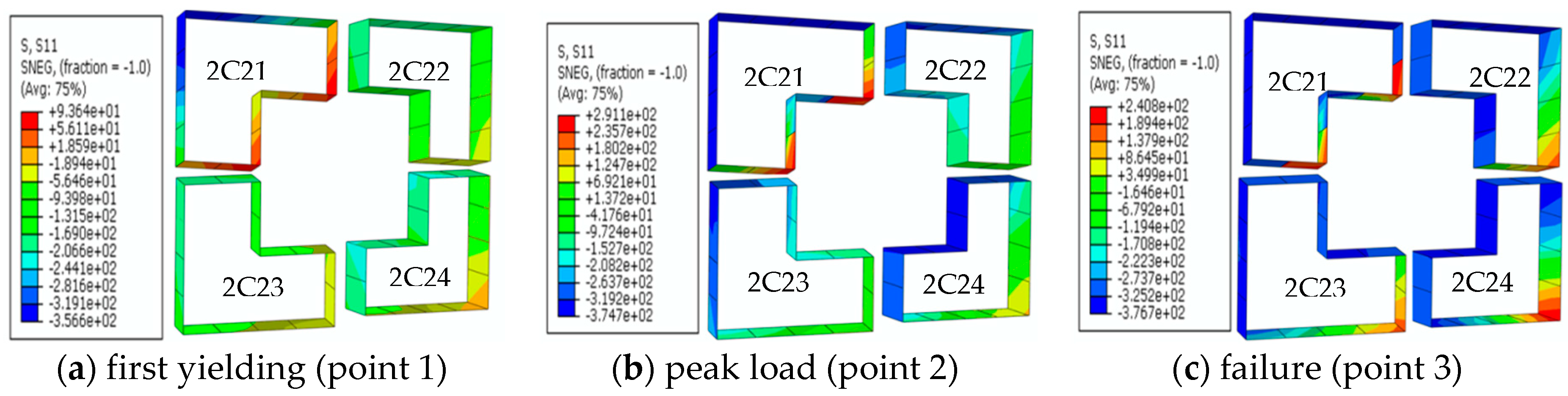
The modeling of the test specimen CF4 was selected as a typical model to study the behavior of the L-shaped composite spatial frames. The horizontal load-versus horizontal displacement curve for a typical sample of a concrete-filled steel tubular frame that was provided by FEA is shown in Figure 10. To investigate the stress state of the frames at different critical locations and under different load levels, the characteristic points corresponding to the three typical moments are selected in the whole progressive response of the horizontal load-versus horizontal displacement of the frame (see Figure 10). The three characteristic points were taken, as follows: (i) the first point was the yield point of the load-displacement curve of the frame specimen, which means that the composite frame was ending the elastic stage and starts yielding; (ii) the second point was the one corresponding to horizontal peak load Pmax (or the position corresponding to Δmax) of the frame specimen; and, (iii) the third point was the one where the horizontal load capacity of the frame specimen dropped to 85 percent of the peak amplitude. At this time, the frame almost reached failure limit. The columns and beams in frame structures were bending specimens when constant axial load was applied to columns, and the cyclical load was applied to beam end. Therefore, the stress states are also different at different section positions. Several representative cross-sections of the stress state on the frame column are selected for analysis. The cross-section position number is shown in Figure 11, where sections are taken at the base of the frame column (C11–C14) and the top of the column (C21–C24), respectively. The cross section (B1–B8) was taken at the beam end (plastic hinge) of the frame beam. All sections were taken offset by 100 mm from the edge of the specimen to avoid the influence of the stress concentration at the base of column and the joint.
The stress distribution of the core concrete at the bottom and top of both the first-story and second-story columns at different loading levels were shown in Figure 12, Figure 13, Figure 14 and Figure 15. It could be seen from all figures that there were a tension zone and a compression zone in the cross section. With the horizontal load increasing, the area of the compression zone of the section gradually decreased, shown from (a) to (c) in Figure 12, Figure 13, Figure 14 and Figure 15. The reason for this phenomenon was that the frame column first subjected the axial load. At the stage, the steel tubular and the concrete were in the state of full section compression. With the increase of the horizontal load, the uniform compression of the entire section was transformed into a non-uniform pressure of the core concrete of frame column, and then the tension zone appeared. Corresponding to the different loading levels, the stress of the concrete at the bottom section of the column developed differently. At first yielding (point 1 in Figure 10), the cross-section was gradually transformed from the full section in compression when there was no horizontal load to the part of section in tension along the horizontal plane of the load. The other area was still the compression zone, but the stress in the compression zone was greater than the corresponding compressive stress when there was no horizontal load. As the load increased, the tension zone area in concrete on the bottom section of the column increased, however the pressure area had decreased from first point to second point. When the frame passed through the peak load (point 2 in Figure 10), the horizontal load decreased, and when the failure load reached (point 3 in Figure 10), finally, the area of the concrete in the tension zone was reduced when compared to the point 2, and the area of the concrete in the compression zone was increased with unloading. Due to local buckling occurred in the steel tubes, then the presence of plastic hinges on the bottom of column, the restraint effect of the steel tubes on the concrete was reduced, and the stress level of the concrete was also reduced. From the concrete stress distribution diagram at the top of the column, it could be seen that the stress distribution of the concrete at the top of the first story and the second story were different. For the top of the second frame column, the distribution of the tension zone and pressure zone was opposite to the distribution of the tension zone and compression zone at the bottom of the column. The compression zone was on the side near the horizontal load point, and the other side was the tension zone. For the top section of the first frame column, there was no obvious tension zone in the stress distribution of the concrete in the top section of the bottom column, and the stress distribution of the entire section of the column was uniform.
The stress distribution diagrams of the steel tubes of the concrete-filled steel frame CF4 specimen at different loading points were shown in Figure 16, Figure 17, Figure 18 and Figure 19. Through the analysis of the finite element stress distribution of the frame model, it could be seen that the stress of the steel tubes at the bottom of the frame column reached the yield stress when horizontal load reached point 1, as shown in Figure 16, Figure 17, Figure 18 and Figure 19a. The major reason was that the frame column already had axial load before the horizontal load. Therefore, the steel tube had been subjected to compressive stress. When the horizontal load continuously increased, the stress of the steel tubes in the compression zone of the column was the superposition of the axial compressive stress and the bending compressive stress, and the yield strength reached, as shown in Figure 16, Figure 17, Figure 18 and Figure 19a. In the steel tubes tension zone, part of the axial compressive stress needed to be offset first because of the bending tensile stress. In general, the absolute value of the stress in the steel section of the compression zone in the same section was larger than that in the tension zone. In other words, the structure subjected to the vertical load. Under the lateral load, the vertical load appeared perpendicular to the vertical axis component after deformation, and this component increased the horizontal displacement. This effect of making the structure geometrically nonlinear was called the second-order effect of gravity (P-Δ). In the test, it showed the inequality of stress in the compression zone and the tension zone. According to the frame design of the strong column weak beam, the plastic hinge firstly appeared at the end of the frame beam, and the concrete did not reach the strength limit when the frame column steel tubes reached the yield limit. When the stress of the concrete continued to increase, the load-carrying capacity of the frame also continued to increase until the frame reached its ultimate capacity. A further explanation for this was that the steel continued to strengthen after reaching the ultimate bearing capacity, and then the concrete was crushed, the plastic hinge formed, and the frame was destroyed. As the horizontal load increased, the yielding steel gradually expanded into the interior of the web. When the load reaches the peak frame load (point 2), most of the stress in the steel tubes at the bottom of the frame column reaches the yield strength, as shown in Figure 16, Figure 17, Figure 18 and Figure 19b. Thereafter, the horizontal load capacity of the frame is unloaded due to the increase of the horizontal displacement. When the frame load unloading is less than 85% of the peak load (that is, the frame structure reaches the limit state, corresponding to point 3), the stress of the steel tubes at the bottom of the frame column reaches the yield limit, and the steel tubes undergoes external drum buckling deformation, and the bottom of column forms a plastic hinge. The stress contour is shown in Figure 16, Figure 17, Figure 18 and Figure 19c.
6. Conclusions
The seismic damage and behavior of L-shaped CFST column frames that were subjected to combined constant axial compressive load and cyclic lateral loading were investigated through a numerical model. A FEA model was established by using commercial finite element software ABAQUS. The accuracy of this proposed numerical model was validated by the experimental test results. The effects of the axial compressive load ratio and lateral loading direction were studied. Four L-shaped CFST column frame specimens were fabricated and tested. The main findings and conclusions from those investigations are summarized, as follows:
- (1).
- the experimental results showed that the steel beam connected to L-shaped concrete-filled steel tubular column spatial frames had high earthquake resistance capacity. The failure modes of this composite frame followed the principle of the strong-column-weak-beam and strong-joints;
- (2).
- the FEA model developed in this paper was able to simulate the behavior of L-shaped concrete-filled steel tubular column spatial frames that were subjected to combined constant axial load and cyclic lateral loading accurately;
- (3).
- an effective stress-strain constitutive model was proposed in this paper, which described the behavior of confined concrete in L-shaped steel tube accurately. The interface and contact model introduced in the model improved the performance of the model in simulating the real behavior of the specimen; and,
- (4).
- cased on the results of the nonlinear analysis, the stress developing progress of L-shaped CFST columns was investigated. The load transferring mechanism and failure mechanism can be determined effectively.
It should be noted that the effect of the bond-slip between steel tube and concrete and the restoring force model of the composite frame both had strong effect on the behavior of the composite structures. The influence of those structural variables should be further studied in future research works. At the same time, only envelope curves were employed in the FEA simulation. The cyclic loading effect, which is an important issue, will be studied while using the developed model in the future.
Author Contributions
J.Z. and Y.Z. conceived and designed the experiments; J.Z. performed the experiments; Y.L. analyzed the data; J.Z. and Y.Z. wrote the paper. Z.W. proofread and revised the paper.
Funding
This research received no external funding.
Acknowledgments
This research work was supported by the National Natural Science Foundation of China (No. 51778065) and the National Natural Science Foundation of China (innovation group) (No. 51378077) and Science and Technology Research Project of Education Department of Hubei Province, China (No. D20151304). The tests were conducted in College of Civil Engineering at Tongji University, Shanghai 200092, PR China. These supports are highly appreciated.
Conflicts of Interest
The authors declare no conflict of interest.
References
- Han, L.H.; Li, W.; Yang, Y.F. Seismic behaviour of concrete-filled steel tubular frame to RC shear wall high-rise mixed structures. J. Constr. Steel Res. 2009, 65, 1249–1260. [Google Scholar] [CrossRef]
- Chen, J.; Wang, Z.; Yuan, J. Research on the stiffness of concrete filled tubular column and steel beam joint with stiffening ring. J. Build. Struct. 2004, 4, 006. (In Chinese) [Google Scholar]
- Yu, Q.; Tao, Z.; Wu, Y.X. Experimental behaviour of high performance concrete-filled steel tubular columns. Thin-Walled Struct. 2008, 46, 362–370. [Google Scholar] [CrossRef]
- Han, L.H.; Li, W.; Bjorhovde, R. Developments and advanced applications of concrete-filled steel tubular (CFST) structures: Members. J. Constr. Steel Res. 2014, 100, 211–228. [Google Scholar] [CrossRef]
- Sakino, K.; Nakahara, H.; Morino, S.; Nishiyama, I. Behavior of centrally loaded concrete-filled steel-tube short columns. J. Struct. Eng. 2004, 130, 180–188. [Google Scholar] [CrossRef]
- Giakoumelis, G.; Lam, D. Axial capacity of circular concrete-filled tube columns. J. Constr. Steel Res. 2004, 60, 1049–1068. [Google Scholar] [CrossRef] [Green Version]
- Ge, H.; Usami, T. Strength of concrete-filled thin-walled steel box columns: Experiment. J. Struct. Eng. 1992, 118, 3036–3054. [Google Scholar] [CrossRef]
- Roeder, C.W.; Lehman, D.E.; Bishop, E. Strength and stiffness of circular concrete-filled tubes. J. Struct. Eng. 2010, 136, 1545–1553. [Google Scholar] [CrossRef]
- Wang, Z.B.; Tao, Z.; Han, L.H.; Uy, B.; Lam, D.; Kang, W.H. Strength, stiffness and ductility of concrete-filled steel columns under axial compression. Eng. Struct. 2017, 135, 209–221. [Google Scholar] [CrossRef] [Green Version]
- Wu, L.Y.; Chung, L.L.; Tsai, S.F.; Shen, T.J.; Huang, G.L. Seismic behavior of bolted beam-to-column connections for concrete filled steel tube. J. Constr. Steel Res. 2005, 61, 1387–1410. [Google Scholar] [CrossRef]
- Ding, F.X.; Yin, G.A.; Wang, L.P.; Hu, D.; Chen, G.Q. Seismic performance of a non-through-core concrete between concrete-filled steel tubular columns and reinforced concrete beams. Thin-Walled Struct. 2017, 110, 14–26. [Google Scholar] [CrossRef]
- Zhong, S. Concrete-Filled Steel Tubular Structure, 3rd ed.; Tsinghua University Press: Beijing, China, 2003. (In Chinese) [Google Scholar]
- Guo, L.H.; Wang, Y.Y.; Zhang, S.M. Experimental study of concrete-filled rectangular HSS columns subjected to biaxial bending. Adv. Struct. Eng. 2012, 15, 1329–1344. [Google Scholar] [CrossRef]
- Liu, J.; Yang, Y.; Liu, J.; Zhou, X. Experimental investigation of special-shaped concrete-filled steel tubular column to steel beam connections under cyclic loading. Eng. Struct. 2017, 151, 68–84. [Google Scholar] [CrossRef]
- Yang, Y.; Yang, H.; Zhang, S. Compressive behavior of T-shaped concrete filled steel tubular columns. Int. J. Steel Struct. 2010, 10, 419–430. [Google Scholar] [CrossRef]
- Shen, Z.Y.; Lei, M.; Li, Y.Q.; Lin, Z.Y.; Luo, J.H. Experimental study on seismic behavior of concrete-filled L-shaped steel tube columns. Adv. Struct. Eng. 2013, 16, 1235–1247. [Google Scholar] [CrossRef]
- Chen, Z.H.; Zhou, T.; Wang, X.D. Application of special shaped column composed of concrete-filled steel tubes. In Advanced Materials Research; Trans Tech Publications: Zürich, Switzerland, 2011; Volume 163, pp. 196–199. [Google Scholar]
- Chen, Z.Y.; Shen, Z.Y. Behavior of L-shaped concrete-filled steel stub columns under axial loading: Experiment. Adv. Steel Constr. 2010, 6, 688–697. [Google Scholar]
- Gang, C.J.S. Experimental investigation on L-shaped concrete-filled steel tube stub columns with binding bars under axial load. China Civ. Eng. J. 2008, 9, 4. (In Chinese) [Google Scholar]
- ZHI, C.; Bin, R.; Fafitis, A. Axial Compression Stability of a Crisscross Section Column Composed of Concrete-Filled Square Steel Tubes; Mathematical Sciences Publishers: Berkeley, CA, USA, 2009; p. 1787. [Google Scholar]
- Zhou, T.; Chen, Z.; Liu, H. Seismic behavior of special shaped column composed of concrete filled steel tubes. J. Constr. Steel Res. 2012, 75, 131–141. [Google Scholar] [CrossRef]
- Patel, V.I.; Liang, Q.Q.; Hadi, M.N.S. Numerical analysis of high-strength concrete-filled steel tubular slender beam-columns under cyclic loading. J. Constr. Steel Res. 2012, 92, 183–194. [Google Scholar] [CrossRef]
- Patel, V.I.; Liang, Q.Q.; Hadi, M.N.S. Inelastic stability analysis of high strength rectangular concrete-filled steel tubular slender beam-columns. Interact. Multiscale Mech. 2012, 5, 91–104. [Google Scholar] [CrossRef] [Green Version]
- Patel, V.I.; Liang, Q.Q.; Hadi, M.N. Nonlinear inelastic behavior of circular concrete-filled steel tubular slender beam-columns with preload effects. In Proceedings of the 10th International Conference on Advances in Steel Concrete Composite and Hybrid Structures, Singapore, 2–4 July 2012. [Google Scholar]
- Herrera, R.; Ricles, J.M.; Sause, R.; Lewis, B. Seismic Performance Evaluation of Steel Moment Resisting Frames With Concrete Filled Tube Columns. In Proceedings of the International Workshop on Steel and Concrete Composite Construction (IWSCCC-2003), Taipei, Taiwan, 8–9 October 2003; pp. 143–152. [Google Scholar]
- Dasgupta, P.; Goel, S.C.; Parra-Montesinos, G.; Tsai, T.C. Performance-based seismic design and behavior of a composite buckling restrained braced frame. In Proceedings of the 13th World Conference on Earthquake Engineering, Vancouver, BC, Canada, 1–6 August 2004; pp. 1–6. [Google Scholar]
- Liu, W.; Li, J. Pseudostatic test on the RC frame with special-shaped columns. Struct. Eng. 2002, 3, 56–61. (In Chinese) [Google Scholar]
- Han, L.H.; Wang, W.D.; Tao, Z. Performance of circular CFST column to steel beam frames under lateral cyclic loading. J. Constr. Steel Res. 2011, 67, 876–890. [Google Scholar] [CrossRef]
- Li, B.; Xue, G.; Zhang, Y. Experimental study on seismic behavior of concrete-filled steel tubular frame. Earthq. Eng. Eng. Vib. 2002, 22, 53–56. (In Chinese) [Google Scholar]
- Wang, W.D.; Han, L.H.; Zhao, X.L. Analytical behavior of frames with steel beams to concrete-filled steel tubular column. J. Constr. Steel Res. 2009, 65, 497–508. [Google Scholar] [CrossRef]
- Wang, T.C.; Lu, M.Q.; Zhang, H.B. Analysis of the effect of slenderness ratio on the ductility of CFRT frames. J. Harbin Inst. Technol. 2005, 3, 14. [Google Scholar]
- Hu, J.W.; Kang, Y.S.; Choi, D.H.; Park, T. Seismic design, performance, and behavior of composite-moment frames with steel beam-to-concrete filled tube column connections. Int. J. Steel Struct. 2010, 10, 177–191. [Google Scholar] [CrossRef]
- Park, T.; Hwang, W.S.; Leon, R.T.; Hu, J.W. Damage evaluation of composite-special moment frames with concrete-filled tube columns under strong seismic loads. KSCE J. Civ. Eng. 2011, 15, 1381–1394. [Google Scholar] [CrossRef]
- Wang, X.; Hao, J.; Zhou, G.; Zhang, Y.; Ma, Y. Experimental research on seismic behavior of two-story two-bay concrete-filled square steel tubucolumns frame. Earthq. Eng. Eng. Vib. 2010, 30, 70–76. [Google Scholar]
- Wang, X.; Ma, Y.; Wang, L.; Hao, J.; Luo, G. Experimental study and nonlinear finite element analysis of seismic behavior of concrete-filled square steel tubular frame. Earthq. Eng. Eng. Vib. 2013, 33, 126–133. [Google Scholar]
- Zhou, T.; Jia, Y.; Xu, M.; Wang, X.; Chen, Z. Experimental study on the seismic performance of L-shaped column composed of concrete-filled steel tubes frame structures. J. Constr. Steel Res. 2015, 114, 77–88. [Google Scholar] [CrossRef]
- Xu, C. Experimental and Theoretical Research on Seismic Behavior of Concrete-Filled Steel Tubular Frames. Ph.D. Thesis, Tianjin University, Tianjin, China, 2003. [Google Scholar]
- Wang, L. Experimental and Theoretical Research on Seismic Behavior of Concrete-Filled Rectangular Steel Tubular Frames. Ph.D. Thesis, Tianjin University, Tianjin, China, 2005. [Google Scholar]
- Hu, X.; Zhu, H.; Wang, D. A study of concrete slab damage detection based on the electromechanical impedance method. Sensors 2014, 14, 19897–19909. [Google Scholar] [CrossRef] [PubMed]
- Xu, J.; Hao, J.; Li, H.; Luo, M.; Guo, W.; Li, W. Experimental Damage Identification of a Model Reticulated Shell. Appl. Sci. 2017, 7, 362. [Google Scholar] [CrossRef]
- Kong, Q.; Robert, R.H.; Silva, P.; Mo, Y.L. Cyclic crack monitoring of a reinforced concrete column under simulated pseudo-dynamic loading using piezoceramic-based smart aggregates. Appl. Sci. 2016, 6, 341. [Google Scholar] [CrossRef]
- Song, G.; Wang, C.; Wang, B. Structural Health Monitoring (SHM) of Civil Structures; MDPI: Basel, Switzerland, 2017. [Google Scholar]
- Yang, Y.; Divsholi, B.S.; Soh, C.K. A reusable PZT transducer for monitoring initial hydration and structural health of concrete. Sensors 2010, 10, 5193–5208. [Google Scholar] [CrossRef] [PubMed]
- Yan, S.; Ma, H.; Li, P.; Song, G.; Wu, J. Development and Application of a Structural Health Monitoring System Based on Wireless Smart Aggregates. Sensors 2017, 17, 1641. [Google Scholar] [CrossRef] [PubMed]
- Yin, H.; Wang, T.; Yang, D.; Liu, S.; Shao, J.; Li, Y. A smart washer for bolt looseness monitoring based on piezoelectric active sensing method. Appl. Sci. 2016, 6, 320. [Google Scholar] [CrossRef]
- Perez-Ramirez, C.A.; Jaen-Cuellar, A.Y.; Valtierra-Rodriguez, M.; Dominguez-Gonzalez, A.; Osornio-Rios, R.A.; Romero-Troncoso, R.D.J.; Amezquita-Sanchez, J.P. A two-step strategy for system identification of civil structures for Structural Health Monitoring using wavelet transform and genetic algorithms. Appl. Sci. 2017, 7, 111. [Google Scholar] [CrossRef]
- Huo, L.; Wang, F.; Li, H.; Song, G. A fractal contact theory based model for bolted connection looseness monitoring using piezoceramic transducers. Smart Mater. Struct. 2017, 26, 104010. [Google Scholar] [CrossRef]
- Wang, F.; Huo, L.; Song, G. A piezoelectric active sensing method for quantitative monitoring of bolt loosening using energy dissipation caused by tangential damping based on the fractal contact theory. Smart Mater. Struct. 2017, 27, 015023. [Google Scholar] [CrossRef] [Green Version]
- Wang, F.; Ho, S.C.M.; Huo, L.; Song, G. A Novel Fractal Contact-Electromechanical Impedance Model for Quantitative Monitoring of Bolted Joint Looseness. IEEE Access 2018, 6, 40212–40220. [Google Scholar] [CrossRef]
- Fang, Z.; Li, A.; Li, W.; Shen, S. Wind-Induced Fatigue Analysis of High-Rise Steel Structures Using Equivalent Structural Stress Method. Appl. Sci. 2017, 7, 71. [Google Scholar] [CrossRef]
- Zeng, L.; Xiao, Y.; Chen, Y.; Jin, S.; Xie, W.; Li, X. Seismic Damage Evaluation of Concrete-Encased Steel Frame-Reinforced Concrete Core Tube Buildings Based on Dynamic Characteristics. Appl. Sci. 2017, 7, 314. [Google Scholar] [CrossRef]
- Tao, Q.L. Research on the Damage Model of SRC Frame-RC Core Wall Hybrid Structure under Seismic Excitation. Ph.D. Thesis, Xi’an University of Architecture and Technology, Xi’an, China, 2011. [Google Scholar]
- Moslehy, Y.; Gu, H.; Belarbi, A.; Mo, Y.L.; Song, G. Smart aggregate based damage detection of circular RC columns under cyclic combined loading. Smart Mater. Struct. 2010, 19, 065021. [Google Scholar] [CrossRef] [Green Version]
- Huang, Q.; Xu, B.; Li, B.; Song, G.B.; Teng, J. Monitoring for large cross-section CFSTs of a super high-rise building with piezoceramic actuators and sensors. In Advanced Materials Research; Trans Tech Publications: Zürich, Switzerland, 2011; Volume 163, pp. 2553–2559. [Google Scholar]
- Xu, B.; Zhang, T.; Song, G.; Gu, H. Active interface debonding detection of a concrete-filled steel tube with piezoelectric technologies using wavelet packet analysis. Mech. Syst. Signal Process. 2013, 36, 7–17. [Google Scholar] [CrossRef]
- Xu, B.; Li, B.; Song, G. Active debonding detection for large rectangular CFSTs based on wavelet packet energy spectrum with piezoceramics. J. Struct. Eng. 2012, 139, 1435–1443. [Google Scholar] [CrossRef]
- Qin, F.; Kong, Q.; Li, M.; Mo, Y.L.; Song, G.; Fan, F. Bond slip detection of steel plate and concrete beams using smart aggregates. Smart Mater. Struct. 2015, 24, 115039. [Google Scholar] [CrossRef]
- Zeng, L.; Parvasi, S.M.; Kong, Q.; Huo, L.; Li, M.; Song, G. Bond slip detection of concrete-encased composite structure using shear wave based active sensing approach. Smart Mater. Struct. 2015, 24, 125026. [Google Scholar] [CrossRef]
- Zhang, J.; Shen, Z.; Lin, Z.; Luo, J. Experimental research on seismic behavior of concrete-filled L-section steel tubular frames. J. Build. Struct. 2010, 31, 1–7. [Google Scholar]
- Zhong, S. Concrete-Filled Steel Tubular Structure; Heilongjiang Science and Technology Press: Haerbin, China, 1999. [Google Scholar]
- Han, L.H. Theory and Practice of Concrete Filled Steel Tubular Structure; Science Press: Beijing, China, 2007. [Google Scholar]
- Lubliner, J.; Oliver, J.; Oller, S.; Oñate, E. A Plastic-Damage Model for Concrete. Int. J. Solids Struct. 1989, 25, 299–329. [Google Scholar] [CrossRef]
- Lee, J.; Fenves, G.L. Plastic-Damage Model for Cyclic Loading of Concrete Structures. J. Eng. Mech. 1998, 124, 892–900. [Google Scholar] [CrossRef]
- Zhang, J.; Shen, H.; Zhou, Z. Nonlinear fem analysis of seismic behavior of l-shaped concrete-filled steel tubular column. Ind. Constr. 2010, 7, 26. [Google Scholar]
- Zhang, J.C.; Lin, Z.Y. Finite element analysis on mechanical properties of special-shaped concerete-filled steel tubular column under low cyclic loading. J. Wuhan Inst. Technol. 2010, 5, 18. [Google Scholar]
- Johansson, M. Structural Behavior of Circular Steel-Concrete Composite Columns: Non-Linear Finite Element Analyses and Experiments. Master’s Thesis, Chalmers University of Technology, Goteborg, Sweden, 2000. [Google Scholar]
- Varma, A.H. Seismic Behavior, Analysis, and Design of High Strength Square Concrete Filled Steel Tube (CFT) Columns. Ph.D. Thesis, Lehigh University, Bethlehem, PA, USA, 2000. [Google Scholar]
- Baltay, P.; Gjelsvik, A. Coefficient of friction for steel on concrete at high normal stress. J. Mater. Civ. Eng. 1990, 2, 46–49. [Google Scholar] [CrossRef]
- Schneider, S.P. Axially loaded concrete-filled steel tubes. J. Struct. Eng. 1998, 124, 1125–1138. [Google Scholar] [CrossRef]
- Susantha, K.A.S.; Ge, H.B.; Usami, T. Confinement evaluation of concrete-filled box-shaped steel columns. Steel Compos. Struct. 2001, 1, 313–328. [Google Scholar] [CrossRef]
- Hu, H.-T.; Huang, C.S.; Wu, M.H.; Wu, Y.M. Nonlinear analysis of axially loaded concrete-filled tube columns with confinement effect. J. Struct. Eng. 2003, 129, 1322–1329. [Google Scholar] [CrossRef]
- Tao, Z.; Uy, B.; Han, L.H.; Wang, Z.B. Analysis and design of concrete-filled stiffened thin-walled steel tubular columns under axial compression. Thin-Walled Struct. 2009, 47, 1544–1556. [Google Scholar] [CrossRef]
- Lu, F.W.; Li, S.P.; Li, D.W.; Sun, G. Flexural behavior of concrete filled non-uni-thickness walled rectangular steel tube. J. Constr. Steel Res. 2007, 63, 1051–1057. [Google Scholar] [CrossRef]
- Aziz, R.J.; Al-Hadithy, L.K.; Resen, S.M. Finite Element Modelling of Concrete Filled Double Skin Steel Tubular Columns under Cyclic Axial Compression Load. Al-Nahrain J. Eng. Sci. 2017, 20, 326–340. [Google Scholar]
- ATC-24. Guidelines for Cyclic Seismic Testing of Components of Buildings; Report No. ATC-24; Applied Technology Council: Redwood City, CA, USA, 1992. [Google Scholar]
- Han, L.H.; Huang, H.; Tao, Z.; Zhao, X.L. Concrete-filled double skin steel tubular (CFDST) beam–columns subjected to cyclic bending. Eng. Struct. 2006, 28, 1698–1714. [Google Scholar] [CrossRef]
- Kawaguchi, J.; Morino, S.; Sugimoto, T. Elasto-plastic behavior of concrete-filled steel tubular frames. In Composite Construction in Steel and Concrete III; ASCE: Reston, VA, USA, 1997; pp. 272–281. [Google Scholar]
- Tomii, M.; Sakino, K.; Xiao, Y.; Watanabe, K. Earthquake resisting hysteretic behavior of reinforced concrete short columns confined by steel tube. In Proceedings of the International Specialty Conference on Concrete Filled Steel Tubular Structures, Harbin, China, 12–15 August 1985; pp. 119–125. [Google Scholar]
- Matsui, C. Strength and behavior of frames with concrete filled square steel tubular columns under earthquake loading. In Proceedings of the International Specialty Conference on Concrete Filled Steel Tubular Structures, Harbin, China, 12–15 August 1985; pp. 104–111. [Google Scholar]
- Zhang, J.C.; Shen, Z.Y.; Lin, Z.Y. Behavior of L-Shaped Concrete-Filled Steel Tubular Columns Subjected to Axial-Compression. J. Guilin Univ. Technol. 2011, 1, 13. [Google Scholar]
- Lin, Z.Y.; Shen, Z.Y.; Luo, J.H.; Zhang, J.C. Study on behavior of L-shaped concrete-filled steel tube stubs subjected to axial compression. Prog. Steel Build. Struct. 2009, 11, 14–19. [Google Scholar]
Figure 1.
The stress-strain curve of steel.
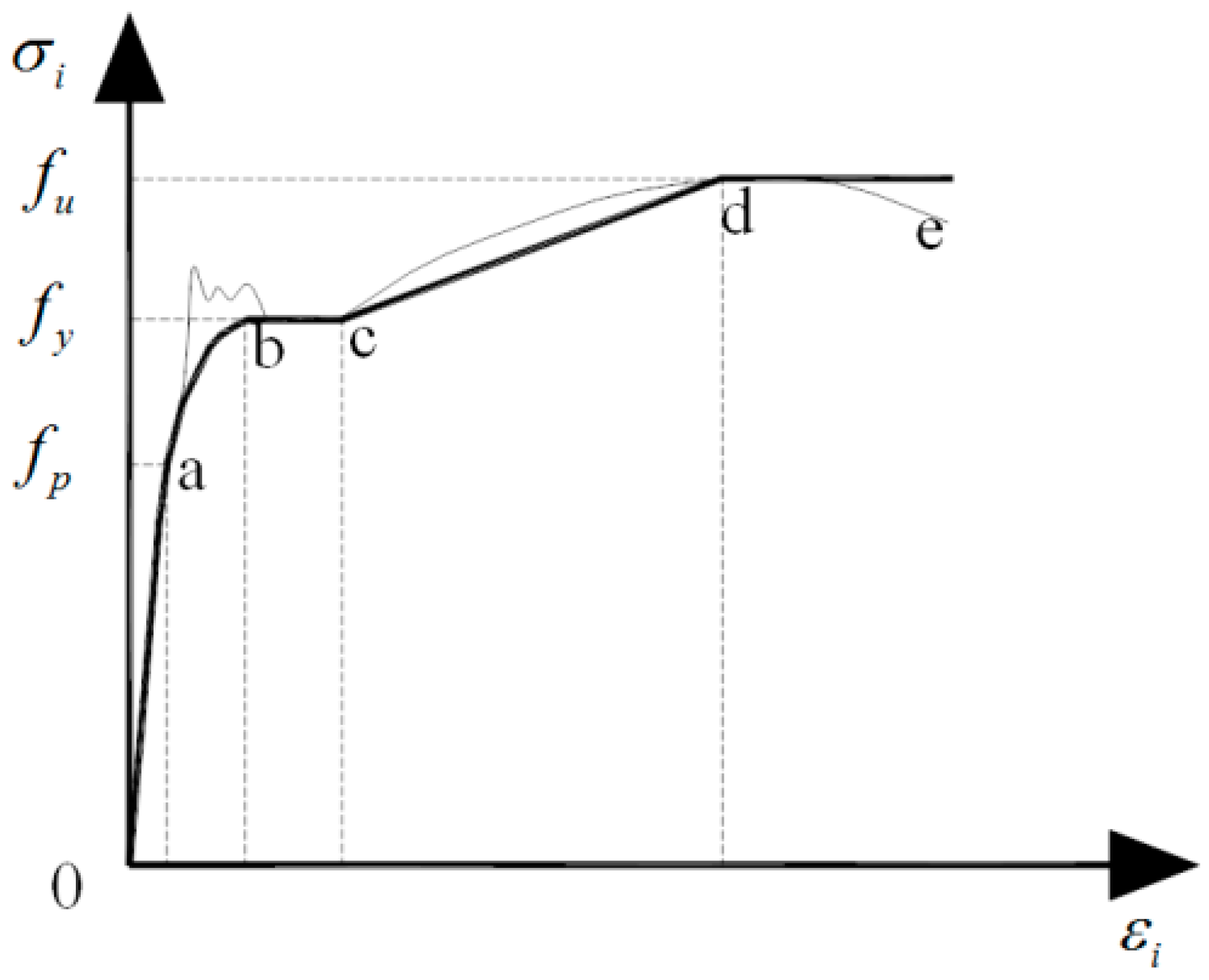
Figure 2.
The equivalent stress-strain curve of core concrete.
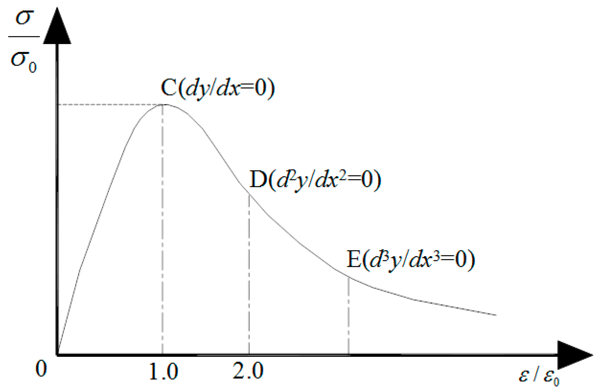
Figure 3.
Typical finite element models of the L-shaped concrete-filled steel tubular (CFST) frame. (a) CF1 and CF2; (b) CF3 and CF4.
Figure 3.
Typical finite element models of the L-shaped concrete-filled steel tubular (CFST) frame. (a) CF1 and CF2; (b) CF3 and CF4.

Figure 4.
Test setup of CF1 and CF2. (a) Elevation view; (b) Photo of the specimen under test.
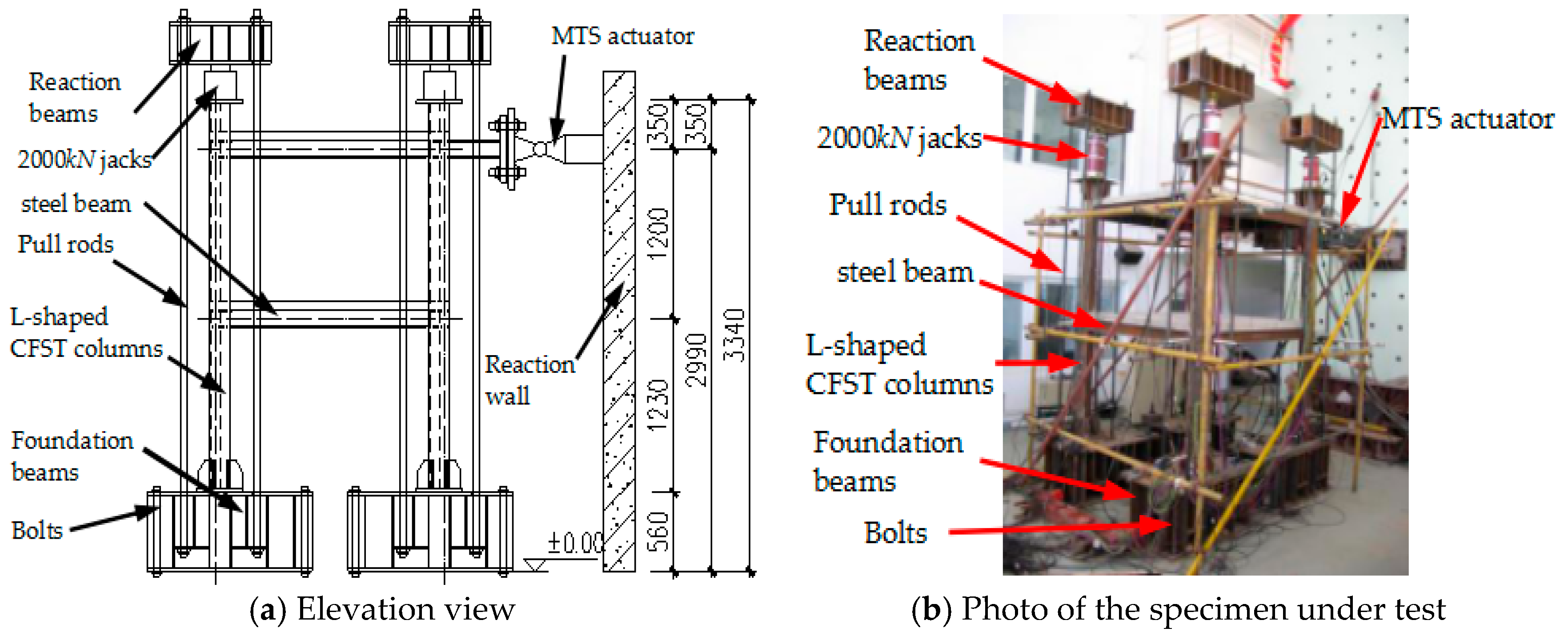
Figure 5.
Test setup of CF3 and CF4. (a) Elevation view; (b) Photo of the specimen under test.
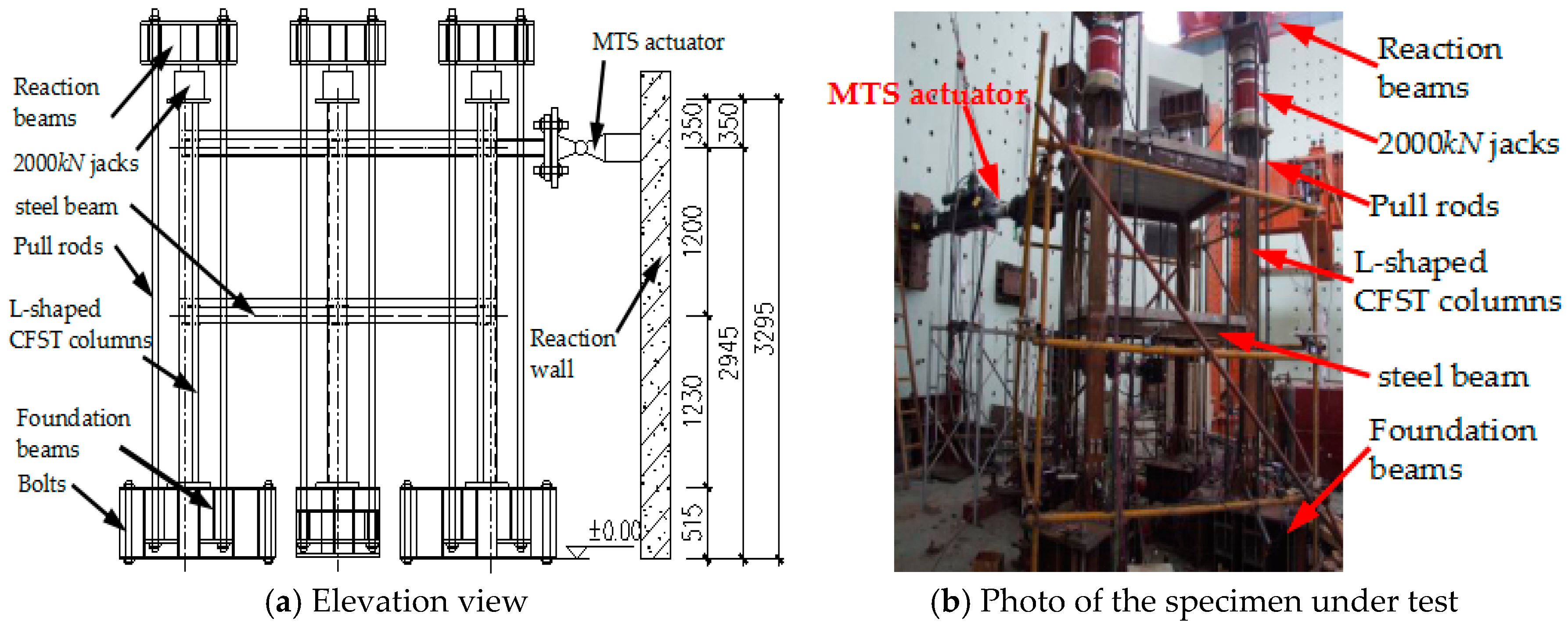
Figure 6.
Typical failure mode of the CF2 spatial frames. (a) Column top; (b) Beam end of the second story; (c) Beam end of the first story; and, (d) Column bottom.
Figure 6.
Typical failure mode of the CF2 spatial frames. (a) Column top; (b) Beam end of the second story; (c) Beam end of the first story; and, (d) Column bottom.
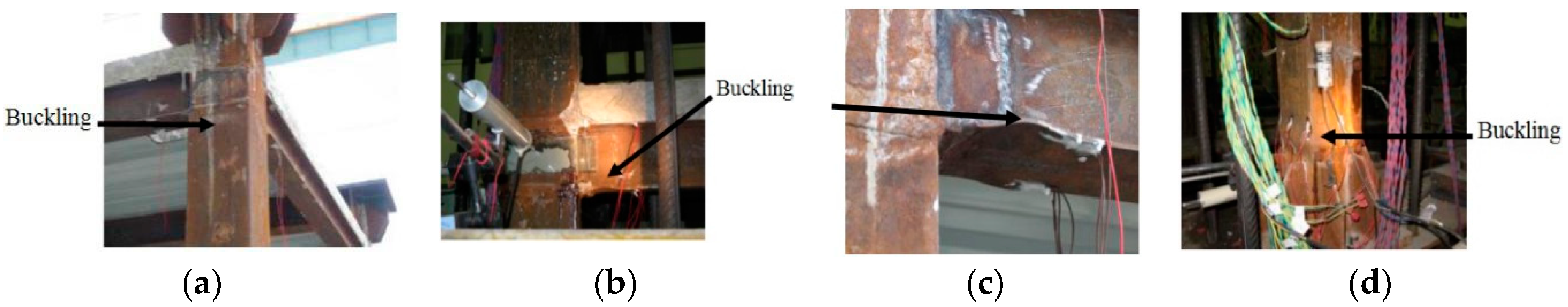
Figure 7.
Hysteretic curves of the lateral load (a,b) versus the lateral displacement (c,d).
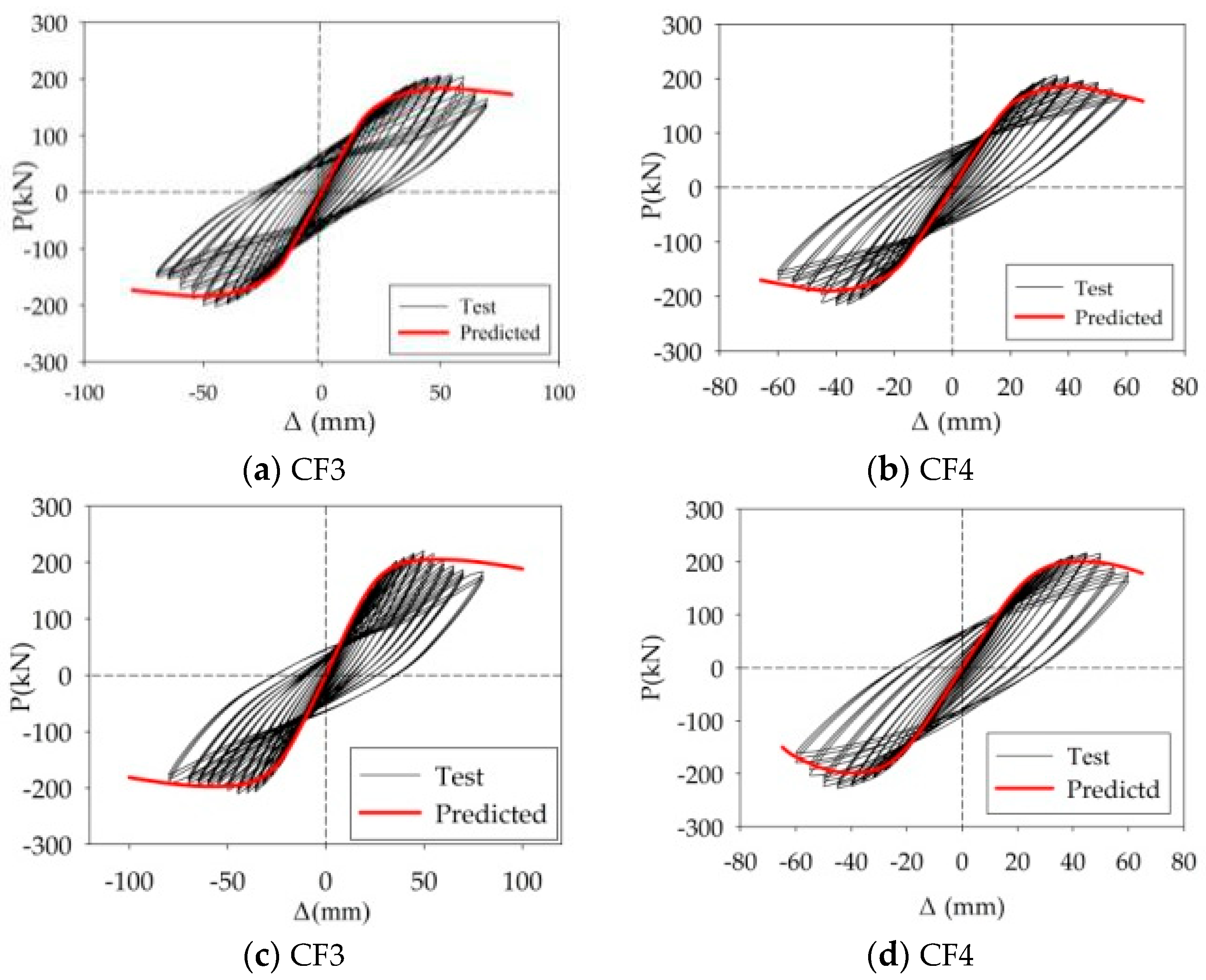
Figure 8.
Comparisons of skeleton curves of frame specimens.

Figure 9.
Comparison of measured envelops curves and computed monotonic curves.

Figure 10.
The horizontal load-versus horizontal displacement curve relation of typical L-shaped CFST frames (CF4).
Figure 10.
The horizontal load-versus horizontal displacement curve relation of typical L-shaped CFST frames (CF4).
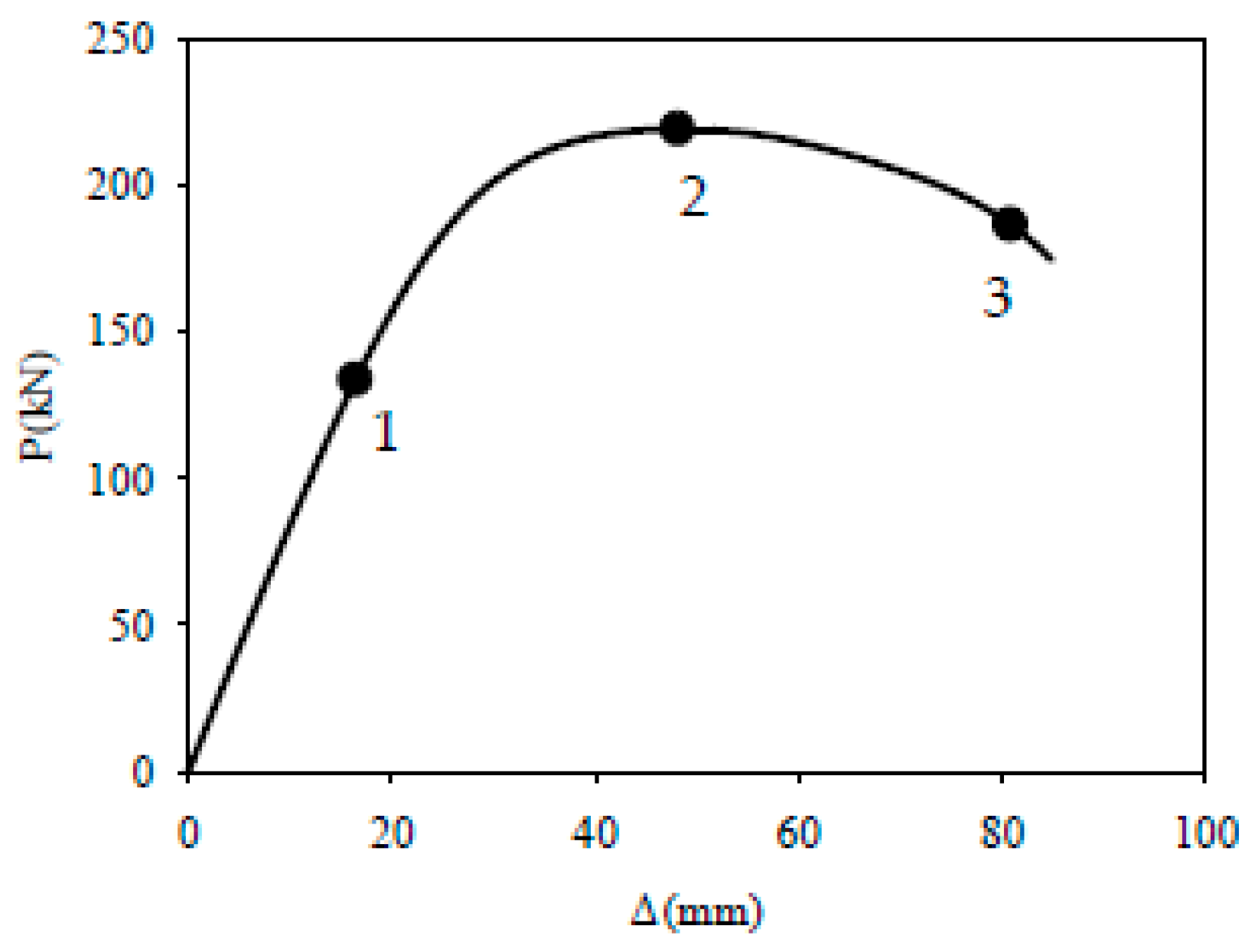
Figure 11.
Typical section location of CF4.
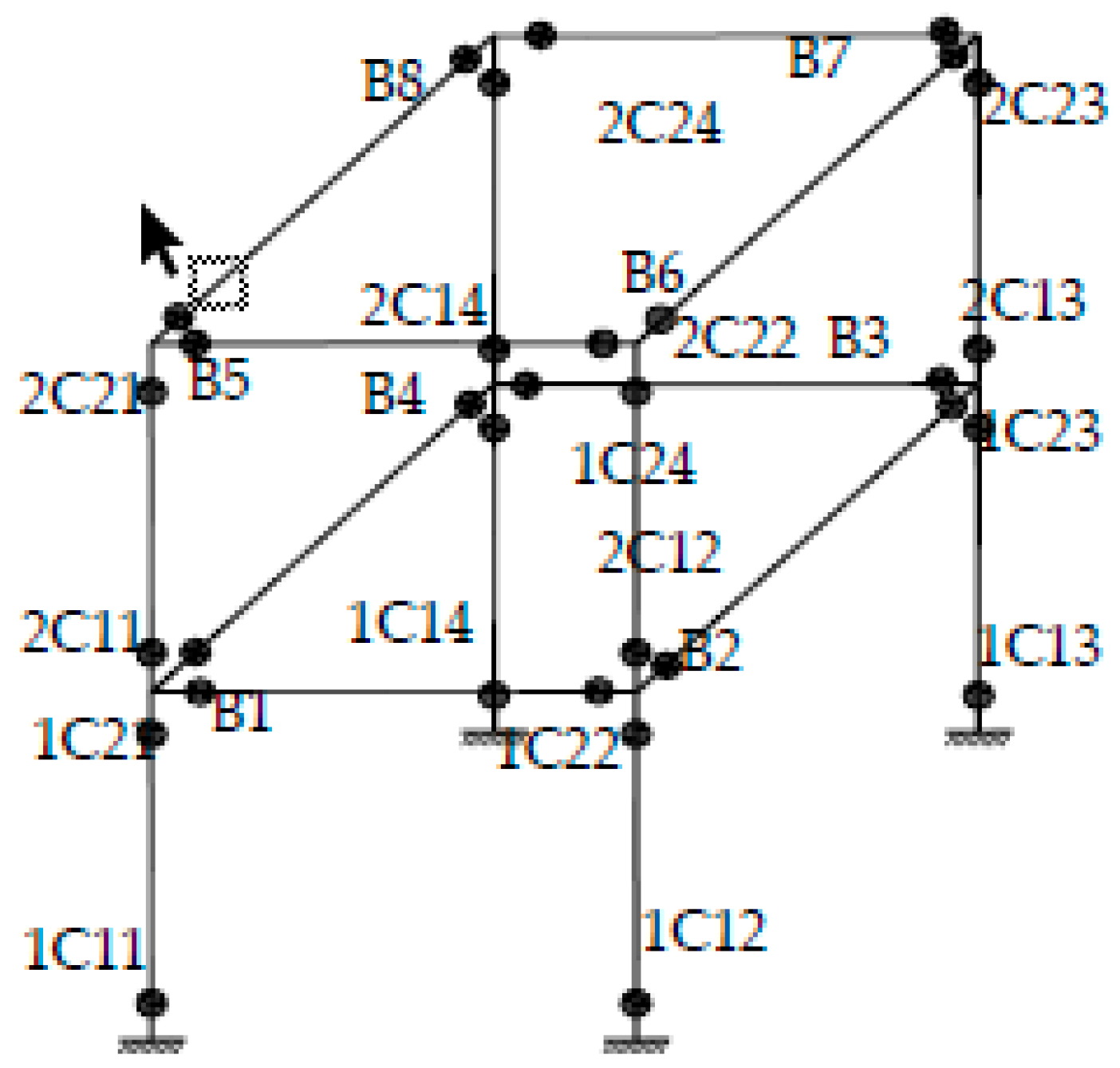
Figure 12.
Stress distribution of concrete at the bottom of the first-story columns (CF4). (Unit: MPa)
Figure 12.
Stress distribution of concrete at the bottom of the first-story columns (CF4). (Unit: MPa)
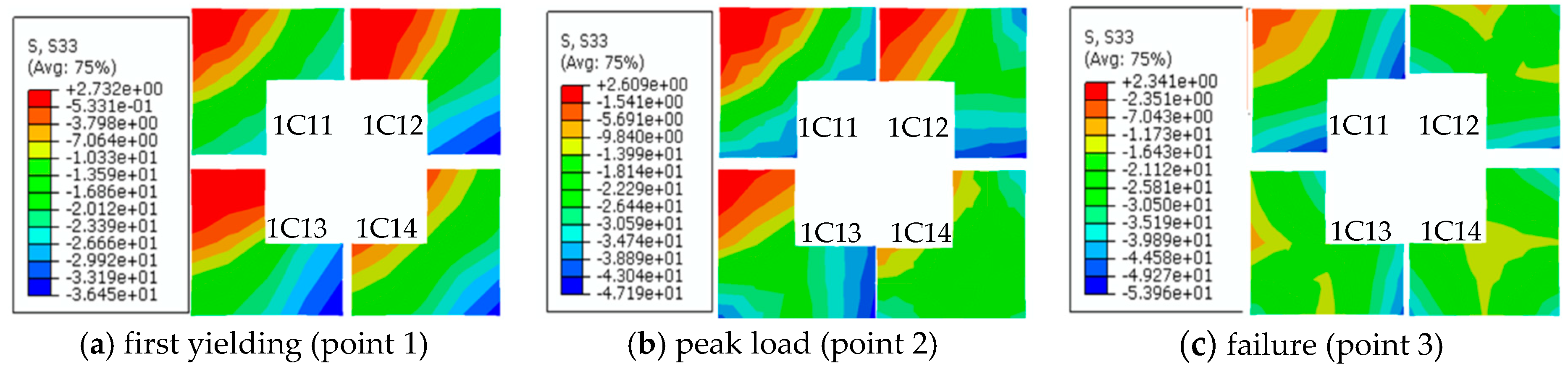
Figure 13.
Stress distribution of concrete at the top of the first-story columns (CF4). (Unit: MPa)
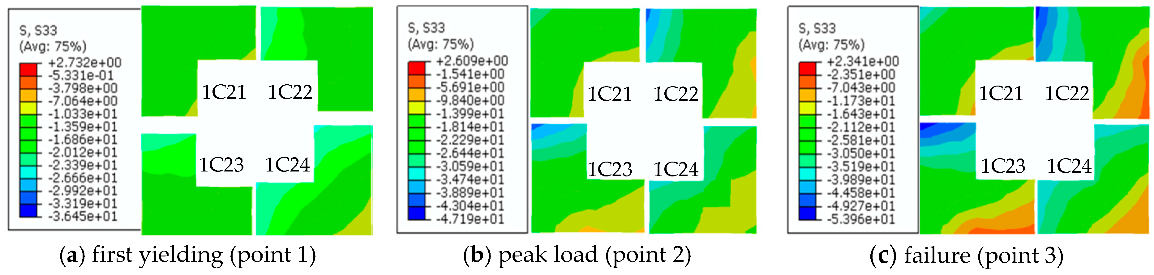
Figure 14.
Stress distribution of concrete at the bottom of the second-story columns (CF4). (Unit: MPa)
Figure 14.
Stress distribution of concrete at the bottom of the second-story columns (CF4). (Unit: MPa)

Figure 15.
Stress distribution of concrete at the top of the second-story columns (CF4). (Unit: MPa)
Figure 15.
Stress distribution of concrete at the top of the second-story columns (CF4). (Unit: MPa)
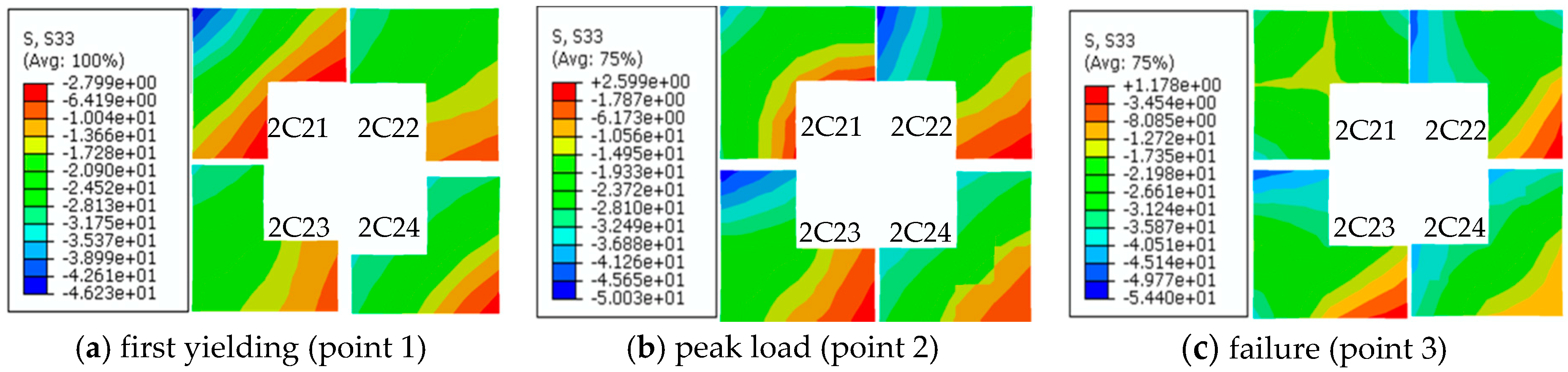
Figure 16.
Stress distribution of steel tubular at the bottom of the first-story columns (CF4). (Unit: MPa)
Figure 16.
Stress distribution of steel tubular at the bottom of the first-story columns (CF4). (Unit: MPa)
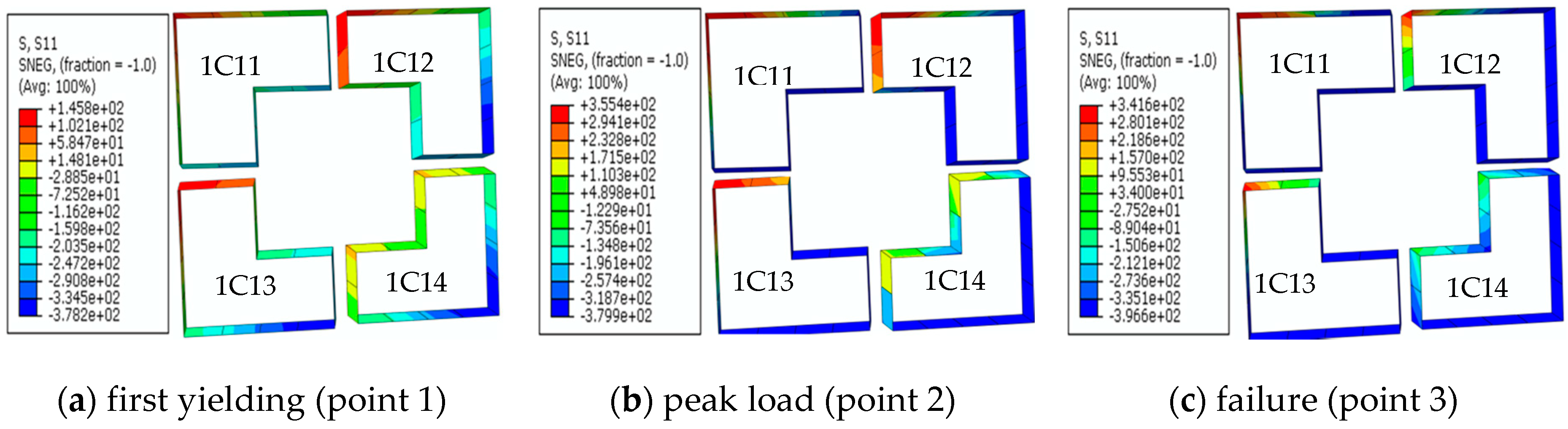
Figure 17.
Stress distribution of steel tubular at the top of the first-story columns (CF4). (Unit: MPa).
Figure 17.
Stress distribution of steel tubular at the top of the first-story columns (CF4). (Unit: MPa).
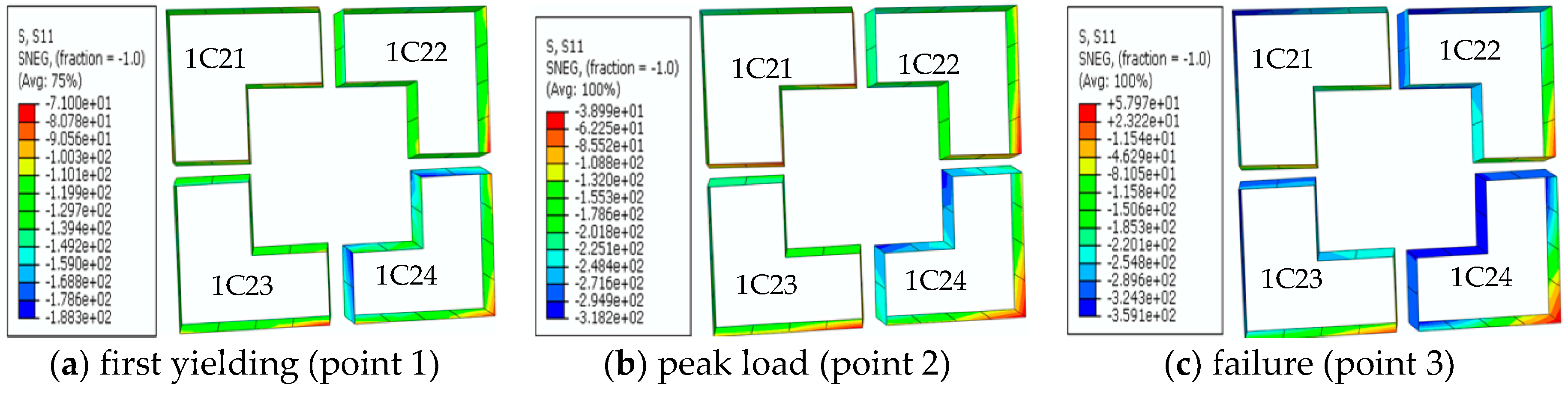
Figure 18.
Stress distribution of steel tubular at the bottom of the second-story columns (CF4). (Unit: MPa)
Figure 18.
Stress distribution of steel tubular at the bottom of the second-story columns (CF4). (Unit: MPa)
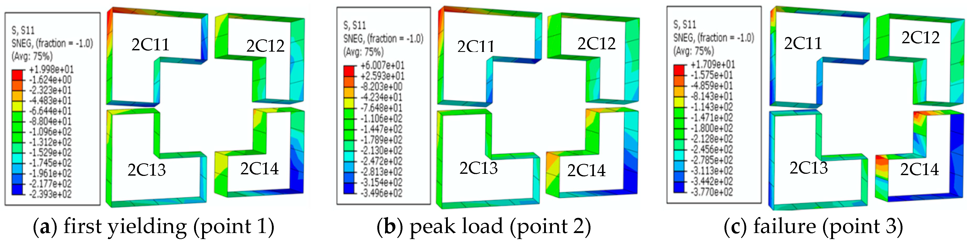
Figure 19.
Stress distribution of steel tubular at the top of the second-story columns (CF4). (Unit: MPa)
Figure 19.
Stress distribution of steel tubular at the top of the second-story columns (CF4). (Unit: MPa)

Table 1.
The design parameters of specimen.
| CF | D (mm) | B (mm) | T (mm) | C | n | N |
|---|---|---|---|---|---|---|
| CF1 | 160 | 80 | 4 | C40 | 00 | 0.4 |
| CF2 | 160 | 80 | 4 | C40 | 00 | 0.6 |
| CF3 | 160 | 80 | 4 | C40 | 450 | 0.4 |
| CF4 | 160 | 80 | 4 | C40 | 450 | 0.6 |
CF is the model number of frames; D is the limb length of columns; B is the limb width of column; T is the thickness of steel tube; C is the core concrete class; n is the direction of lateral load on frames; N is the axial compressive load ratio on columns.
Table 2.
The mechanical parameter of steel.
| Steel Type | t (mm) | fy (MPa) | fu (MPa) | Es (MPa) |
|---|---|---|---|---|
| Tubes | 3.64 | 355 | 472 | 1.82 |
| Beam | 3.75 | 362 | 485 | 1.79 |
t is the thickness; fy is the yield strength; fu is the ultimate strength; Es is the elastic modulus.
Table 3.
Displacement-controlled loading protocol.
| Total Horizontal Displacement, x (mm) | x ≤ 10 | 10 ˂ x ≤ 20 | 20 ˂ x |
|---|---|---|---|
| Each stage displacement increments (mm) | 2 | 2 | 5 |
| Number of cycles | 1 | 3 | 3 |
Table 4.
Comparison of ultimate values by experiments and finite element model (FEM).
| CF | Standard Deviation | Coefficient of Variation | |||
|---|---|---|---|---|---|
| CF1 | 188.7 | 207.5 | 0.909 | 0.014 | 1.5% |
| CF2 | 185.8 | 206.1 | 0.902 | ||
| CF3 | 205.4 | 220.7 | 0.931 | ||
| CF4 | 200.9 | 216.7 | 0.927 |
is the maximum lateral load-carrying capacity of the specimen by FEM is the maximum lateral load-carrying capacity of the specimen from experiment.
© 2018 by the authors. Licensee MDPI, Basel, Switzerland. This article is an open access article distributed under the terms and conditions of the Creative Commons Attribution (CC BY) license (http://creativecommons.org/licenses/by/4.0/).
Share and Cite
MDPI and ACS Style
Zhang, J.; Li, Y.; Zheng, Y.; Wang, Z. Seismic Damage Investigation of Spatial Frames with Steel Beams Connected to L-Shaped Concrete-Filled Steel Tubular (CFST) Columns. Appl. Sci. 2018, 8, 1713. https://doi.org/10.3390/app8101713
AMA Style
Zhang J, Li Y, Zheng Y, Wang Z. Seismic Damage Investigation of Spatial Frames with Steel Beams Connected to L-Shaped Concrete-Filled Steel Tubular (CFST) Columns. Applied Sciences. 2018; 8(10):1713. https://doi.org/10.3390/app8101713
Chicago/Turabian StyleZhang, Jicheng, Yong Li, Yu Zheng, and Zhijie Wang. 2018. "Seismic Damage Investigation of Spatial Frames with Steel Beams Connected to L-Shaped Concrete-Filled Steel Tubular (CFST) Columns" Applied Sciences 8, no. 10: 1713. https://doi.org/10.3390/app8101713
Note that from the first issue of 2016, this journal uses article numbers instead of page numbers. See further details here.