Abstract
In this paper, we investigate jamming attacks in the physical layer against cooperative communications networks, where a jammer tries to block the data communication between the source and destination. An energy-constrained relay is able to assist the source to forward the data to the destination even when the jammer tries to block the direct link. Due to a limited-capacity battery of the relay, a non-radio frequency energy harvester equipped in the relay helps to prolong its operation. We propose a scheme based on a partially observable Markov decision process (POMDP) to find the optimal action for the source such that we can maximize the achievable throughput of cooperative communications networks. Under this scheme, the source dynamically selects the appropriate action mode for its transmission in order to obtain maximum throughput under the jamming attack. Simulation results verify that the proposed scheme is superior to the Myopic scheme where only current throughput is taken into account for making decisions.
1. Introduction
Cooperative communications are used to effectively improve the quality of a wireless network. The reliability and capacity of wireless communications are substantially increased by deploying the cooperative communication technique. In a cooperative communication system, each user can directly transmit data and collaborate with other users (i.e., relays) to transmit its data to a destination for enhancing the quality of transmissions [1]. In this case, an intermediate relay is used to support the transmissions between the source and the destination. Cooperative communications can offer remarkable advantages for wireless networks such as high energy efficiency and extended network lifetime [2,3]. Recently, several studies have showed that cooperative communications can help to enhance the capacity and reliability of the wireless networks [4,5,6].
The physical layer is the lowest layer in the Open Systems Interconnection (OSI) model. It can be used to verify the physical properties of a transmission in the network. However, the broadcast nature of wireless communications leaves the physical layer vulnerable to threats, e.g., eavesdropping, node tampering, hardware hacking, and jamming attacks [7]. In an eavesdropping attack, the eavesdropper can overhear the confidential information of legitimate users and occupy the data in the transmission area of a node. In node tampering, the attacker can replace the entire physical node or part of the node. Hardware hacking can damage nodes via malicious entities such that the nodes can lose their expected functionality, leaving them vulnerable to other risks. In jamming attacks, a jammer attempts to prevent users from accessing wireless network resources and reduces network availability by generating interference signals on the channels. This exhausts the energy of the nodes in the network [8,9].
A cooperative communications network is particularly vulnerable to malicious attacks in the physical layer. Moreover, jamming is one of the more serious attacks that greatly degrade network performance. In order to tackle the jamming attacks, frequency hopping spread spectrum and direct sequence spread spectrum are widely utilized [10]. However, the same sequence can be used by the jammer to attack its target if the hopping sequence is exposed. Thus, the random rendezvous [11] and the uncoordinated frequency hopping [12] are used to safely share the hopping sequence. Nevertheless, these techniques result in the time wastes for the communications. Therefore, other secret sharing protocols are proposed such as public key cryptography, certificate and authentication protocol but they cause the large overheads and computational [13]. Desmedt [14] proposed an efficient coding method that provides protection against malicious users. Popper et al. [15] applied the uncoordinated spread spectrum (USS) techniques to prevent jamming of the communications between transmitter and receiver. USS achieved effective anti-jamming by discarding the require secrets before sharing, at the expense of a decreased communications throughput. However, USS techniques require the complex frequency synthesizers. Chorti derived optimal power allocation policies for transmitter and receiver pairs, where the active jammer is formulated as a one-shot zero-sum game for anti-jamming in secret key-generation systems [16]. Almost all the previous works on anti-jamming focus on how to design physical layer technologies (e.g., spread spectrum) [10,12,15,17,18,19]. If the signals are widely spread, it will become harder for the jammer to interrupt the transmission link; meanwhile, the complexity in spread spectrum technique may be enlarged and thus it is not easy to deploy in the reality.
Recently, various jammer localization schemes have been proposed in wireless communications [20,21]. The authors in [20] use spatial information as the basis for detecting the attacks to verify the number of attackers and localize the ambient adversaries. In [21], the authors consider the multiple jammers scenario in which multiple jammers can attack the network at the same time to achieve a better jamming effect. They propose the jamming detection scheme by developing X-rayed jammed-area localization algorithm. However, measurement data collection and position information sharing will bring more challenges. In [22], the authors investigate the multi-hop multi-channel cognitive radio network in the presence of multiple jammers. To deal with the energy-constrained problem, two novel algorithms are proposed to maximize the energy efficiency of data transmission from the source to the destination under the jamming attacks. Although the simulation results can verify the effectiveness of the proposed scheme, the applicable metrics may be limited due to the high overheads and algorithm complexity when the number of intermediate relays in the network is large. The digital feedback scheme is proposed to improve the speed of transceivers and it is also proved to be robust to noise in the feedback channel [23]. In order to deal with the energy-constrained issue and resource scarcity, the authors developed the joint controller and the related supporting access protocol to maximize both the energy and bandwidth efficiency of the vehicular access network, which is guaranteed to be reliable and safe in the wireless communication [24].
Recently, energy harvesting has become one of the appealing techniques for solving the energy-constraint problem in wireless networks. Practically, user equipment units (UEs) often are equipped with a limited-capacity battery. That results in degradation of network performance due to limited energy for the operation. Thus, energy harvesting technique can provide permanent energy for the battery without any physical replacements. Fortunately, UEs can harvest energy from non-radio frequency (RF) signals (e.g., solar, wind, heat, etc.) [25] or from RF signals [26,27], which are available in ambient environments.
In this paper, we consider the jamming attack scenario in cooperative communication system that consists of a source, a destination, a relay, and a jammer where the jammer intends to inject interference signals to block the transmission link (from the source to destination). The jammer in this paper is assumed to always broadcast enough the interference (power) to block the communication in its communication range when it is actived. We define the jammer as “absolute jammer”. The behavior of the jammer is assumed to follow the Markov chain model.
In order to deal with the challenge of the jammer, we propose to use a relay to help the source to forward the data to the destination. However, the relay is assumed to be a small and movable device (for easy set up). Subsequently, the relay has a small battery that can allow the device to work in a limited time. The energy harvesting technique is applied to deal with energy-constrained problem at the relay; however, the limited energy arrival rate is also taken into account where the relay can harvest non-RF energy from the ambient environment with a limited amount of energy in each time slot [22,25]. Moreover, the imperfection of the spectrum sensing mechanism [20,21,28] on the jamming detection at the source is also considered.
This paper aims to maximize the long-term achievable throughput of the cooperative communication system in which the source will make the optimal decision on whether or not the source should cooperate with the relay to transmit the data to the destination securely with the purpose of degrading the jamming effect. We formulate the problem based on the POMDP framework [28] and propose a novel scheme to obtain the optimal policy such that the source can select the best action in every single time slot by considering long-term throughput maximization. The main contributions of this paper are summarized as follows
- We investigate the throughput maximization of the cooperative communication system under the jamming attack, where an intermediate relay equipped with a limited-capacity battery is deployed to securely facilitate the transmission from the source to the destination. Meanwhile, due to the limited energy of the jammer, the jamming attack operation is assumed to follow the Markov chain model.
- We consider the imperfection of the spectrum sensing as well as the non-RF energy harvesting model at the relay for long-term operation, which greatly affects the network performance in practice.
- We propose a POMDP-based scheme at the source node to determine the optimal policy in the cooperation with the relay to improve the long-term achievable throughput of the network in the presence of the jamming attack. As a result, according to the optimal policy, the optimal action in every single time slot operation can be obtained using the proposed scheme.
- We evaluate the performance of the proposed scheme in comparison with traditional schemes such as Myopic and Direct Link Only schemes via Matlab simulation under various network conditions. The numerical results are given to show the superior of the proposed scheme as compared with others according to the various network parameters of the cooperative communication network.
The remainder of the paper is organized as follows. In Section 2, we introduce the system model and the Markov chain model of the jammer. In Section 3, we describe the optimal policy for direct and relay-assisted transmission modes. Section 4 evaluates our proposed scheme via simulation results. Finally, we conclude this paper in Section 5. To make it tractable to follow, we indicate the most frequently used symbols in Table 1.

Table 1.
The notation list.
2. System Model
As shown in Figure 1, we consider a cooperative communication network consisting a source, S, a destination, D, a relay, R, and a jammer, J. The source, destination, and jammer are assumed to have a fixed power supply such that they always have enough energy for transmission, reception, and jamming. By using the cooperative technique, S can cooperate with R to maximize the achievable throughput in the presence of the attack performed by J. The network is assumed to follow a synchronous, time-slotted model with time slot duration T. The channel coefficients between S and D, S and R, and R and D are denoted by and , respectively.
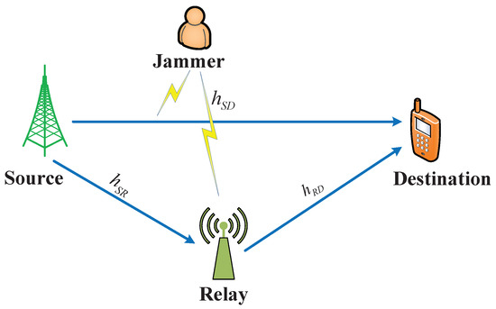
Figure 1.
The system model of the proposed scheme.
In this paper, we consider the “absolute jammer” who always has enough energy to transmit the interference signals to destroy the channel in target transmission link in a whole time slot duration. Therefore, when the jammer attacks the channel, the direct transmission link from the source to the destination will be blocked; and thus, D can not receive the data transmitted from S. Fortunately, R can help the source to forward its data to the destination in this case. However, the relay is assumed to have a limited-capacity battery without any fix powered supplies. Hence, the relay needs to harvest non-RF energy to maintain its long- term operation. The relay is assumed to scavenge energy during a whole time slot T and the harvested energy is stored in a battery with a finite capacity, . Therefore, at time slot tth, the amount of energy (energy units) that is harvested by the relay can be expressed as where are harvested energy levels, and
The probability mass function (PMF) of the harvested energy is given as:
where is the probability of the harvested energy in time slot tth. In this paper, we assume that the harvested energy of the relay follows a Poisson distribution where is a Poisson random variable with mean value , and the PMF in (1) can be rewritten as follows:
In order to deal with the jamming attack problem, at the beginning of each time slot, the source needs to determine whether it should use the direct transmission mode or relay-assisted transmission mode to transmit its data to the destination.
Figure 2a depicts the time frame structure of the direct transmission mode. For this mode, the frame is divided into two phases: sensing and data transmission. In the sensing phase, the source performs spectrum sensing to detect jamming signals infected by the jammer. In the data transmission phase, the source transmits the data to the destination without any help from the relay.
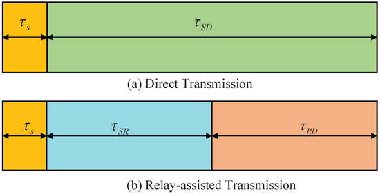
Figure 2.
Frame structure.
Figure 2b illustrates the time frame structure of the relay-assisted transmission mode. For this mode, the frame is divided into three phases: sensing, data transmission from the source to the destination , and data forwarding from the relay to the destination . Unlike direct transmission, after the sensing phase, the source will transmit the data to the relay and then, the relay will forward the data to the destination. represents the sensing time of the source. and represent the data transmission times of the links: S to D, S to R, and R to D, respectively. Note that the duration of sensing phase in relay-assisted transmission mode is the same as direct transmission mode meanwhile the duration . For the direct transmission mode, the received signal of the destination at the end of a time slot can be expressed as follows
where is the transmission power at the source; represents the signal transmitted from the source, is white Gaussian noise (AWGN) with zero- mean and variance at the destination. For the relay-assisted transmission mode, the received signals of the relay after the S-R phase can be expressed as follows
where denotes the white Gaussian noise with zero- mean and variance at the relay. This paper adopts an amplify-and-forward (AF) relaying protocol to forward data to the destination. Hence, the relay amplifies the signal by using a scale factor, , which can be calculated as follows:
where represents the transmission power at the relay.
In phase 2, the received signal at the destination is given by
where denotes jamming noise with zero-mean and variance . Note that in the case that the jammer does not attack, the will be zero. As a result, the signal-to-interference-plus-noise ratio (SINR) at D is denoted as , and for the direct transmission without jamming, relay-assisted transmission with jamming and relay-assisted transmission without jamming, respectively, obtained as follows:
According to the transmission mode, the average throughput can be calculated as
where
and are the probability of false alarm and the probability of detection of the sensing mechanism, respectively, according to sensing time duration . and denote the probability of no jamming and the probability of jamming in the network, respectively. , , and represent achievable throughput at the destination under the different cases in (10), i.e., direct transmission without jamming (10a), relay-assisted transmission with jamming (10b), and relay-assisted transmission without jamming (10c).
The probability of detection and false alarm can be estimated as follows [28]:
and
where denotes energy threshold, M represents for number of sensing samples and can be calculated as ( is sensing bandwidth), is signal-to-noise ratio (SNR) of the sensing channel (i.e., the channel between source and jammer). There are some available researches that propose methods to estimate the SNR value. Therefore, in this paper we assume that the value is available at the source. The probability of false alarm also can be achieved by
In this paper, we assume that the states of the jammer follow a Markov chain model. The states of the jammer changes between the two states, presence (J) and absence (), shown in Figure 3. The transition probabilities of the jammer from state J to state and from state J to itself are denoted as and , respectively [29].
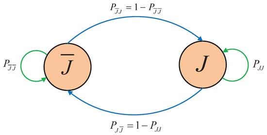
Figure 3.
A Markov chain model of the jammer.
We assume that the source always has a data packet to transmit to the destination. At the beginning of a time slot, the information about remaining energy of the relay ( , ) is assumed to be available at the source.
Figure 4 shows the operation process of the system. First of all, the source performs sensing to identify the states ( “” or “”) of the jammer. If the sensing engine provides the result “”, i.e., there is no jamming signal in the current time slot (not always true due to the imperfect sensing), the source will trust the result and then transmits its data directly to the destination. If the source receives an acknowledge (ACK) message after the transmission phase, then the reward is calculated as
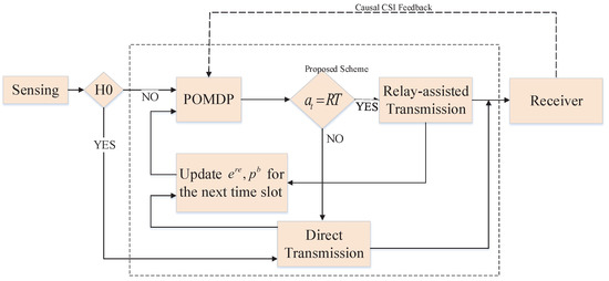
Figure 4.
Flowchart of the proposed scheme.
The belief probability , which represents the probability of the jammer being present in the next time slot, will be updated as
The remaining energy in the battery of the relay can be updated as
where is the amount of harvested energy of the relay in time slot tth.
If the source does not receive an ACK (or receive NACK) after the transmission phase, the reward will be zero (i.e., ). Besides that, the updated belief in the next time slot, , can be calculated as
The transition probability is given as
If the result obtained from the sensing engine is “”, then the proposed scheme, based on a partially observable Markov decision process (POMDP), will be applied to select the optimal action (i.e., either performs the direct transmission mode or relay-assisted transmission mode). The proposed scheme will be presented in more detail in the next section.
3. Optimal Mode Decision Policy Based on POMDP
In this scheme, we apply POMDP to obtain an optimal mode decision policy to maximize the throughput in a cooperative communications network in the presence of the jamming attack. In this system, there are two operation modes for the source: direct transmission () and relay-assisted transmission (), .
In DT mode, the relay will not assist the source to forward the data to the destination (i.e., the relay is inactive for this case). That means the destination will receive the data transmitted directly from the source. In RT mode, the relay will help the source to forward the data to the destination (i.e., the relay is active for this case). Due to the energy-constrained problem in the relay as well as the imperfect spectrum sensing, the source will consider the long-term reward to efficiently cooperate with the relay to optimize the network performance.
In order to formulate the framework of POMDP, we define the state space of the system as where and are the remaining energy of the relay and the probability of the presence of the jammer in time slot tth, respectively. Value function represents the maximum total discounted throughput of the system, which is given by
where denotes the discount factor and it is chosen to adjust the impact of future action to current action. More specifically, if the value of alpha is large, the reward of the future action will more affect to the reward of the current action and vice versa, is the achieved throughput of system in time slot tth when action is performed at the state .
3.1. RT Mode
In the RT mode, the relay will help the source forward data to the destination. In this mode, the destination can always receive data packet, so it will be difficult to distinguish the presence of jamming. From the received signals at the destination, we can realize whether the jammer actually attacks the channel or not. That is because the signal strength from received data packet when the jammer attacks will become stronger than a normal received data packet (i.e., without jamming). Therefore, the destination can recognize whether the original signal contains the jamming signal or not, in terms of the predefined jamming threshold such as
where is the received signal energy at the destination.
Observation 1 : The sensing result indicates the presence of the jammer, the source transmits data packet via the relay and the jammer actually attacks the channel. In this case, jammer attack is well detected, and corresponding achieved throughput is given by
The probability that case happens can be calculated as
The updated belief for the next time slot is computed as
The updated remaining energy for the next time slot is
where is the required energy for transmission from the relay to the destination.
The transition probability can be calculated as
Observation 2 : In this case, the sensing result indicates the presence of the jammer, the source transmits data via the relay, and the jammer actually does not attack the channel. Hence, we recognize the false alarm happens in this case. The achieved throughput is given as
The updated belief for the next time slot is given as
The remaining energy for the next time slot can be updated as
The probability that case happens is
The transition probability if the case happens is
3.2. DT Mode
In direct transmission mode, the source directly transmits the data to the destination (without a help from the relay). According to whether the source receives ACK from destination, the following two observations can be described as follows.
Observation 3 : The source transmits the data directly to the destination and receives an ACK. The achieved throughput is given by
The probability that the case occurs is computed as
The belief that the jammer will be present in the next time slot can be updated as
In this case, although the relay does not receive and forward data to the destination, it still harvests energy for future use. The updated remaining energy of the relay for the next time slot is
The transition probability that the case happens is computed as
Observation 4 : The source transmits data directly to the destination, but it does not receive an ACK. In this case, there is no achieved throughput such that we have . The probability that case happens can be calculated as follows:
The updated belief for the next time slot can be given as
The remaining energy in the relay is updated in the same way as Equation (37) under . The transition probability that case occurs is given by
for .
Based on these observations, we can calculate the expected value function, and further we can find the optimal operation mode, . Therefore, the value function in (22) can be rewritten as follows
In order to solve problem in Equation (42), a numerical method is used [30]. The solution to the problem provides the optimal policy of the system. The complexity of algorithm can be analyzed based on the amount of computation space such as number of states, actions, transition probabilities and observations. Based on the Bellman’s equation, the optimal policy is chosen by solving the value function using iteration-based dynamic programming. Let us denote , be the action set and the possible state set at the beginning of each time slot, respectively. The algorithm complexity can be defined according to the action and state space of the system. In the POMDP, the agent has to control the process at each time step to maximize the long-term reward. Therefore, the number of operations is required in each iteration to calculate total number of the transition probabilities from one state to other state after performing an action .
4. Simulation Results
In order to evaluate the effectiveness of the proposed scheme, we implemented a simulation using MATLAB. In this section, we present the performance comparisons among the proposed scheme, the Myopic scheme and the Direct Link Only scheme. In the Myopic scheme, we only considered the throughput for the current time slot to select optimal action. In the Direct Link Only scheme, the source always uses the direct link to transmit data packet to the destination. The parameters used for our simulation are shown in Table 2.

Table 2.
Simulation parameters.
In Figure 5 shows the average throughput of the system according to the required transmission energy of relay node. According to Figure 5, the throughput of the system decreases as the required transmission energy increases. The reason is as follows: For a large amount of the required transmission energy, the source will have fewer opportunities to transmit the data packet via relay when the jammer appears since the relay lacks energy for the forwarding process. It is obvious that the increase in the required transmission energy does not affect the average throughput of the Direct Link Only scheme. The figure verifies that the proposed scheme outperforms the Myopic scheme and the Direct Link Only scheme.
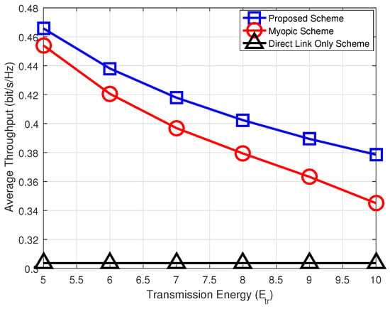
Figure 5.
Average throughput versus required transmitted energy.
Figure 6 shows the relation between average throughput and battery capacity in the relay. We can see that the average throughput of the system increases as the battery capacity of the relay increases. The reason is why the relay has more energy to assist communication between the source and destination. On the other hand, the battery capacity of the relay does not affect the Direct Link Only scheme, and corresponding throughput is not changed. The figure shows that the proposed scheme can provide higher throughput than the Myopic and the Direct Link Only schemes.
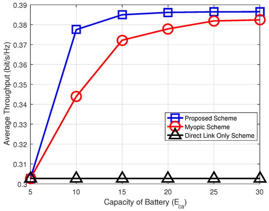
Figure 6.
Average throughput versus capacity of battery.
Figure 7 shows average throughput of the proposed scheme according to the battery capacity of relay node for different values of detection probability . It is observed that average throughput of the proposed scheme increased as the battery capacity of relay node increases for a fixed value of . However, the average throughput of the proposed scheme goes into a saturation mode for a certain value of the battery capacity. That is, as the battery capacity reaches a certain value, the average throughput of the proposed scheme cannot be enhanced. Figure 7 also shows that more detection probability of jammer, the more the average throughput. To do this, however, we need more accurate sensing scheme at the source node.
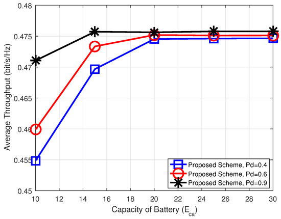
Figure 7.
Average throughput versus capacity of the battery when detection probability , and .
Finally, Figure 8 shows the average throughput of the proposed scheme according to the detection probability of jammer for different values of the required transmission energy of the relay node. As like the previous observation, the more required transmission energy of the relay node, the less the average throughput. For a fixed value of the required transmission energy of the relay node, the average throughput of the proposed scheme is improved as the detection probability of jammer increases.
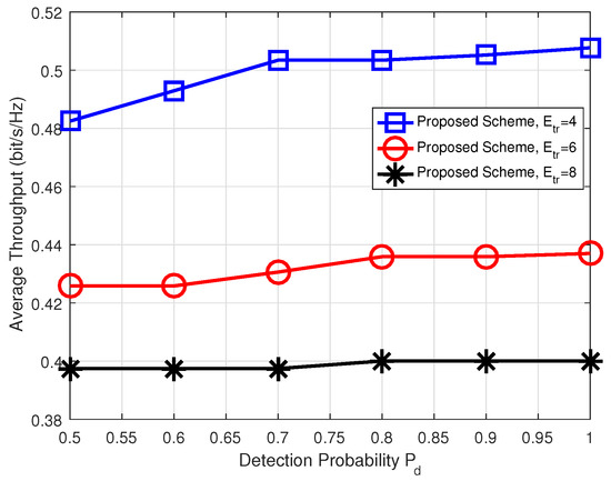
Figure 8.
Average throughput versus detection probability when transmission energy , and 8.
5. Conclusions
In this paper, we investigated the average throughput maximization of cooperative communications networks when under a jamming attack. In addition, the energy-constraint problem was taken into account. We proposed a POMDP-based scheme to achieve the optimal mode decision policy to maximize the long-term throughput by taking into account future reward. Simulation results confirmed that the proposed scheme can improve the overall throughput in cooperative communications networks and outperforms a Myopic scheme and Direct Link Only scheme under the jamming attack. In the future, we would like to investigate the joint relay and channel selection scheme in multiple relays and multiple channels to enhance the overall throughput of the network. Moreover, multiple jammers should be considered and an actor-critic-based scheme should be studied to determine the optimal policy in the cooperation communications networks with energy-constrained relay under multiple jammers. Therefore, it is the key challenge in the future to find the optimal solution for the source to select the best relay and channel in the multiple channels, relays and jammers.
Author Contributions
All authors conceived and proposed the research idea. H.T.H.G. made the formulation and performed the simulations under the supervision of H.V.-V.; I.K. analyzed the simulation results; H.T.H.G. wrote the draft paper; H.V.-V. and I.K. reviewed and edited the paper.
Acknowledgments
This work has supported by the National Research Foundation of Korea (NRF) grant funded by the Korea government (MSIT) (NRF-2018R1A2B6001714).
Conflicts of Interest
The authors declare no conflict of interest.
References
- Norsratinia, A.; Hedayat, A. Cooperative Communication in Wireless Networks. IEEE Commun. Mag. 2004, 42, 74–78. [Google Scholar] [CrossRef]
- Shah, A.F.M.S.; Islam, M.S. A Survey on Cooperative Communication in Wireless Networks. Int. J. Intell. Syst. Appl. 2014, 7, 66–78. [Google Scholar] [CrossRef]
- Tao, X.; Xu, X.; Cui, Q. An overview of cooperative communications. IEEE Commun. Mag. 2012, 50, 65–71. [Google Scholar]
- Cover, T.M.; Gamal, A.A.E. Capacity Theorems for the Relay Channel. IEEE Trans. Inf. Theory 1979, 25, 572–584. [Google Scholar] [CrossRef]
- Laneman, J.N.; Tse, D.N.C.; Wornell, G.W. Cooperative diversity in wireless networks: Efficient protocols and outage behavior. IEEE Trans. Inf. Theory 2004, 50, 3062–3080. [Google Scholar] [CrossRef]
- Laneman, J.N.; Wornell, G.W. Distributed space-timecoded protocols for exploiting cooperative diversity in wireless networks. IEEE Trans. Inf. Theory 2003, 49, 2415–2425. [Google Scholar] [CrossRef]
- Zou, Y.; Zhu, J.; Wang, X.; Hanzo, L. A Survey on Wireless Security: Technical Challenges, Recent Advances and Future Trends. Proc. IEEE 2016, 104, 1727–1765. [Google Scholar] [CrossRef]
- Tomic, I.; McCann, J.A. A Survey of Potential Security Issues in Existing Wireless Sensor Network Protocols. IEEE IoT J. 2017, 4, 1910–1923. [Google Scholar] [CrossRef]
- Thakur, N.; Sankaralingam, A. Introduction to Jamming Attacks and Prevention Techniques using Honeypots in Wireless Networks. Int. J. Comp. Sci. Inf. Technol. Secur. 2013, 3, 202–207. [Google Scholar]
- Schilling, D.; Milstein, L.; Pickholtz, R. Theory of spread spectrum communications. IEEE Trans. Commun. 1982, 30, 855–884. [Google Scholar]
- Huang, J.-F.; Chang, G.-Y.; Huang, J.-X. Anti-jamming rendezvous scheme for cognitive radio networks. IEEE Trans. Mobile Comput. 2017, 16, 648–661. [Google Scholar] [CrossRef]
- Strasser, M.; Pöpper, C.; Capkun, S.; Cagalj, M. Jamming-resistant key establishment using uncoordinated frequency hopping. In Proceedings of the 2008 IEEE Symposium on Security and Privacy (sp 2008), Oakland, CA, USA, 18–22 May 2008; pp. 64–78. [Google Scholar]
- Paek, J. Fast and adaptive mesh access control in low-power and lossy networks. IEEE Internet Things J. 2015, 2, 435–444. [Google Scholar] [CrossRef]
- Desmedt, Y. Broadcast Anti-Jamming Systems. Comput. Netw. 2001, 35, 223–236. [Google Scholar] [CrossRef]
- Popper, C.; Strasser, M.; Capkun, S. Anti-jamming broadcast communication using uncoordinated spread spectrum techniques. IEEE J. Sel. Areas Commun. 2010, 28, 703–715. [Google Scholar] [CrossRef]
- Chorti, A. Overcoming limitations of secret key generation in block fading channels under active attacks. In Proceedings of the IEEE 17th International Workshop on Signal Processing Advances in Wireless Communications (SPAWC), Edinburgh, UK, 3–6 July 2016; pp. 1–5. [Google Scholar]
- Awerbuch, B.; Richa, A.; Scheideler, C. A jamming-resistant mac protocol for single-hop wireless networks. In Proceedings of the Twenty-Seventh ACM Symposium on Principles of Distributed Computing, Toronto, ON, Canada, 18–21 August 2008; pp. 45–54. [Google Scholar]
- Liu, X.; Noubir, G.; Sundaram, R.; Spread, S.T. Foiling smart jammers using multi-layer agility. In Proceedings of the 26th IEEE International Conference on Computer Communications, Barcelona, Spain, 6–12 May 2007; pp. 2536–2540. [Google Scholar]
- Navda, V.; Bohra, A.; Ganguly, S.; Rubenstein, D. Using channel hopping to increase 802.11 resilience to jamming attacks. In Proceedings of the 26th IEEE International Conference on Computer Communications, Barcelona, Spain, 6–12 May 2007; pp. 2526–2530. [Google Scholar]
- Chen, Y.; Yang, J.; Trappe, W.; Martin, R.P. Detecting and localizing identity-based attacks in wireless and sensor networks. IEEE Trans. Veh. Technol. 2010, 59, 2418–2434. [Google Scholar] [CrossRef]
- Cheng, T.; Li, P.; Zhu, S. Multi-jammer localization in wireless sensor networks. In Proceedings of the 2011 Seventh International Conference on Computational Intelligence and Security, Sanya, China, 3–4 Decembar 2011; pp. 736–740. [Google Scholar]
- Thanh, P.-D.; Vu-Van, H.; Koo, I. Efficient channel selection and routing algorithm for multihop, multichannel cognitive radio networks with energy harvesting under jamming attacks. Secur. Commun. Netw. 2018, 2018, 7543212. [Google Scholar] [CrossRef]
- Soleimani, H.; Tomasin, S.; Alizadeh, T.; Shojafar, M. Cluster-head based feedback for simplified time reversal prefiltering in ultra-wideband systems. Phys. Commun. 2017, 25, 100–109. [Google Scholar] [CrossRef]
- Cordeschi, N.; Amendola, D.; Shojafar, M.; Baccarelli, E. Distributed and adaptive resource management in cloud-assisted cognitive radio vehicular networks with hard reliability guarantees. Veh. Commun. 2014, 2, 1–12. [Google Scholar] [CrossRef]
- Bhowmick, A.; Roy, S.D.; Kundu, S. Performance of secondary user with combined RF and non-RF based energy-harvesting in cognitive radio network. In Proceedings of the 2015 IEEE International Conference on Advanced Networks and Telecommuncations Systems (ANTS), Kolkata, India, 15–18 December 2015; pp. 1–3. [Google Scholar]
- Bhowmick, A.; Yadav, K.; Roy, S.D.; Kundu, S. Throughput of an Energy Harvesting Cognitive Radio Network Based on Prediction of Primary User. IEEE Trans. Veh. Technol. 2017, 66, 8119–8128. [Google Scholar] [CrossRef]
- Zhai, C.; Liu, J.; Zheng, L. Cooperative Spectrum Sharing With Wireless Energy Harvesting in Cognitive Radio Networks. IEEE Trans. Veh. Technol. 2016, 65, 5303–5316. [Google Scholar] [CrossRef]
- Vu-Van, H.; Koo, I. Optimal throughput for cognitive radio with energy harvesting in fading wireless channel. Sci. World J. 2014, 2014, 1–7. [Google Scholar] [CrossRef] [PubMed]
- Cadeau, W.; Li, X.H.; Xiong, C.Y. Markov Model Based Jamming and Anti-Jamming Performance Analysis for Cognitive Radio Networks. Commun. Netw. 2014, 6, 76–85. [Google Scholar] [CrossRef]
- Bertsekas, D.P. Dynamic Programming and Optimal Control, 2nd ed.; Athena Scientific: Nashua, NH, USA, 2001; Volumes 1 and 2. [Google Scholar]
© 2018 by the authors. Licensee MDPI, Basel, Switzerland. This article is an open access article distributed under the terms and conditions of the Creative Commons Attribution (CC BY) license (http://creativecommons.org/licenses/by/4.0/).