Dynamic Behavior of a Simple Rolling Seismic Isolator with a Position Restoring Device


1
School of Mechanical & Automotive Engineering, Halla University, Wonju-si, Gangwon-do 26404, Korea
2
Research & Business Corporation Center, Institute for Advanced Engineering, Yongin-si, Gyeonggi-do 17180, Korea
*
Author to whom correspondence should be addressed.
Appl. Sci. 2018, 8(10), 1910; https://doi.org/10.3390/app8101910
Submission received: 5 September 2018
/
Revised: 11 October 2018
/
Accepted: 11 October 2018
/
Published: 14 October 2018
(This article belongs to the Section Mechanical Engineering)
Abstract
:Herein, the behavior of a rolling type seismic isolation system with a position restoring device (PRD) is investigated, for alleviating problems such as rapid convergence and position restoration. The equation of motion is derived by modeling the behavior of the seismic isolation system, and the seismic characteristics according to the design variables of the PRD are investigated through numerical analysis. The vibration characteristics of the equation of motion show nonlinearity and depend on different variables. Numerical analysis was performed by using the fourth and fifth order Runge–Kutta method, and the vibration characteristics were analyzed with respect to the design parameters in the rolling type seismic isolation system with PRD, and compared to a model without PRD. In the model with PRD, numerical results show that the vibration suppression capability of the earthquake and the position restoration after disturbance are improved compared to those of the model without PRD. In addition, the rolling type seismic isolation system had nonlinear characteristics at specific frequencies, where the response increases suddenly and harmonics occur. This phenomenon can be controlled by the ratio of mass to stiffness and the damping coefficient, showing that the mount system can be designed to avoid resonance through optimal design.
1. Introduction
The damage caused by earthquakes has been steadily increasing. In recent years, the scale of the damage has been increasing rapidly as the industry has advanced [1]. Also, to cope with the threats from earthquakes, various types of seismic isolation systems have been introduced and actively studied [2,3]. Isolation systems use a basic separator to reduce the response of the structure caused by the ground vibrations of the earthquake. There are various types of seismic isolation systems, such as sliding bearings, rubber bearings, and rolling bearing isolation systems [4,5]. In recent years, many methods of vibration protection have been developed, including energy dispersion, vibration control, and base isolation [6,7,8]. In addition, studies on anti-vibration rubber bearings (HDRB) have been continuously carried out to increase the damping force of materials, and their probabilistic reliability has been studied [9,10,11,12,13]. Initial research on the rolling bearing seismic isolation system (RIS) was carried out by Lin and Hone in 1993 [14,15]. Their model consists of a flat plate and cylindrical rolling bearings, and is widely used because of its protective effect from earthquakes [16,17]. To overcome the disadvantages of recentering, Tsai [18] constructed an RIS with cylindrical rollers between two V-shaped rolling surfaces, and applied them to a bridge structure. Research on RIS using spherical rollers instead of cylindrical rollers has also been conducted and used for light loads [19]. Although RIS has excellent seismic performance, there is a problem in that the seismic table moves easily in the horizontal direction, even in the case of weak earthquakes or small vibrations around the RIS as well as further issues regarding resonance. In addition, there is a disadvantage that the return to the initial position is delayed or does not occur even after the earthquake due to insufficient restoring force. To overcome the limitations of traditional friction pendulum insulators, Krishnamoorthy developed a variable curvature pendulum isolator and variable friction pendulum isolator and studied the effect of this isolating system [20,21,22]. Variable frequency pendulum isolators (VFPIs) and variable curvature friction pendulum systems (VCFPS) have also been proposed by Pranesh and Sinha and Tsai et al. [23,24]. The products development of new isolation systems is based on step-by-step procedures for theoretical design, manufacturing, and performance verification. The design of manufacturing and performance verification is to improve mechanical properties such as material selection and heat treatment to maintain durability. The rollers and plates that make up the core components in this system are made of materials with high strength, high hardness, and wear resistance. Studies on fatigue, fracture, and reliability have been conducted by analytical and experimental methods, and were performed by Castaldo P., Ghidelli, M., etc. [12,25,26,27,28].
The purpose of this study is to develop the theoretical basis for analyzing seismic characteristics of PRD for the shape design of a new isolation system that combines PRD and RIS in order to improve performance in the design stage. The purpose of the isolation system is as follows.
- Performance that returns the object to the initial position after the earthquake
- Improvement of damping, which is a disadvantage of the RIS system.
- Suppression of movement during weak earthquakes.
- Control of resonance generation in the RIS system.
For this study, theoretical governing equations for the isolation system, the RIS with a PRS, are derived, and nonlinear problems are analyzed using a fourth and fifth order Runge–Kutta method. In addition, the behavior was examined with respect to the movement of the structure, convergence time, occurrence of resonance, and nonlinearity, according to various parameters such as the spring constant, magnitude of seismic input, etc.
2. Equation of Motion
2.1. Description of Analysis Model
The RIS consists of a lower rolling plate with a concave surface called a base table, an upper plate called a superstructure, and rollers between the two plates. The rollers and plates that make up the core components have been manufactured in high carbon chromium bearing steel and chrome molybdenum steel for high mechanical strength, fatigue strength, high hardness, and wear resistance. When the base table is excited by an external force, relative movement of the base and the upper structure is generated, and the rolling friction of the roller acts as a damping force. In this system, the damping force can be controlled by adjusting the coefficient of rolling friction. Since the potential energy change of the superstructure is small at the center, when the friction coefficient is increased, the frictional force is increased, and the upper structure is not restored to the original position after the movement, and stops at an arbitrary position. Therefore, it is necessary to provide a PRD for quick restoration to the original position.
As shown in Figure 1, the proposed model consists of a lower rolling plate, a base table with a concave surface, and a PRD for rapid restoration. The PRD is assembled by providing a top plate with a wedge-shaped (or hemispherical) groove and a spring-damper-sliding unit that is installed on the base table by precompressing the spring. This device prevents the superstructure from moving horizontally due to a weak earthquake or unnecessary vibration, and makes it return to the initial position quickly after the earthquake. Stick-slip friction occurs at the contact surface between the spring tip of the device and the wedge hole.
In Figure 1, is the radius of the concave surface of the base table, is the radius of the roller, and is the seismic displacement of the base table; and are the relative and absolute horizontal displacements of the superstructure, respectively, and have the following relationship with the base displacement,
The horizontal displacement and the vertical displacement of the base table have the following geometric relationships, respectively.
2.2. Equation of Motion
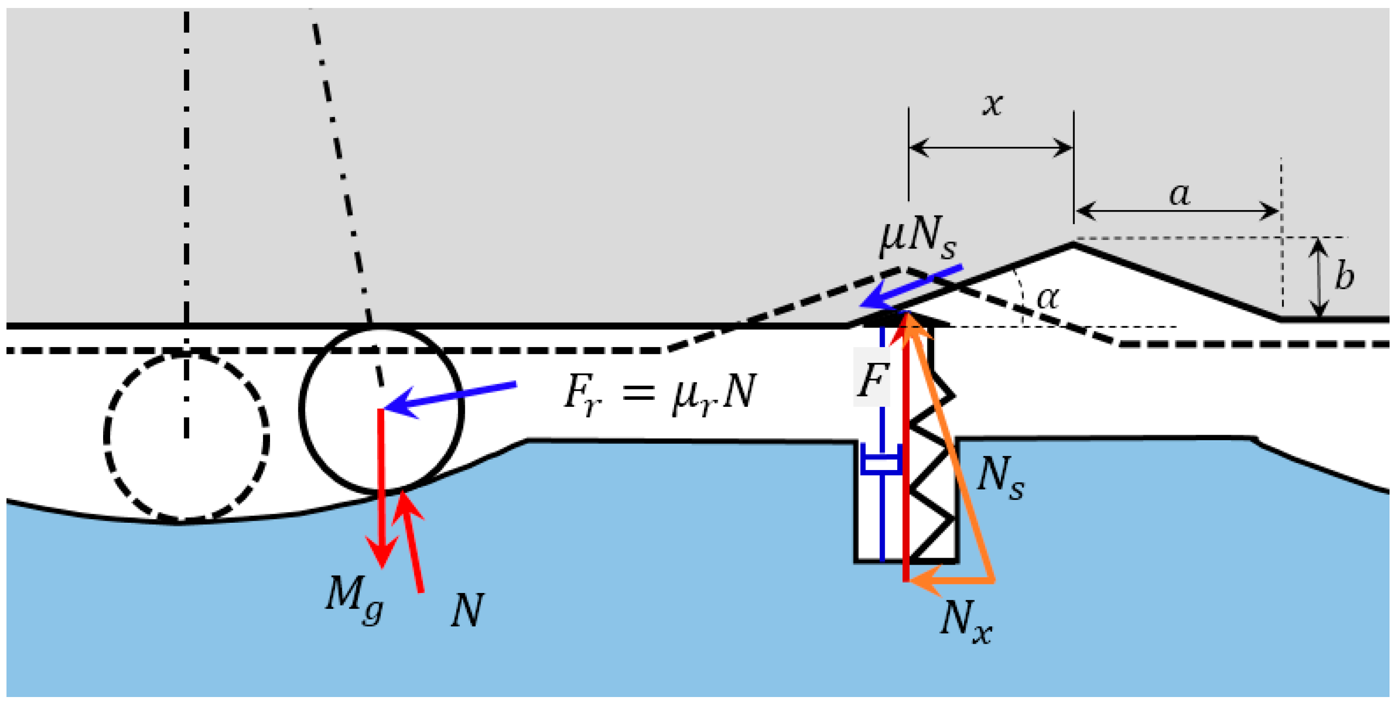
In this paper, a rolling-type isolator system with PRD is established in Figure 2, and the assumptions to derive the equation of motion are as follows. The superstructure, with a total mass of the , is considered as a rigid structure having only horizontal motion; the rollers and the upper and base plates make rolling contact without slippage; since the mass of the rollers is smaller than the total mass, it is ignored; and that the radius of the concave surface is very large.
The force acting on the system is applied to the gravitational load of the superstructure, the normal force , the rolling resistance on the concave surface, and the vertical reaction and the friction force by the spring ball device, as shown in Figure 2. Here, and are the spring-damper unit force and gravitational acceleration, respectively. is the ratio of the rolling resistant coefficient to the roller radius [29]. In Figure 2, we can see the dimensions of the wedge-shaped hole, which is a symmetric structure with a width of 2a and a height of b. In this study, it is assumed that the PRD plays a role only when the relative displacement x of the superstructure satisfies the condition of . Then, if the compression displacement for the initial preload of this device is the total compression amount for the displacement is as follows,
when , the normal force is the sum of the spring force and damping force , are expressed as follows,
where and are the spring constant and damping coefficient of the PRD, respectively.
From the free body diagram in Figure 2, we can write the equilibrium equations of force for the horizontal and vertical directions when ;
where and ‘’ denotes the sign of the parameter in parentheses. Since the radius of the concave surface is large, it is assumed that the angular displacement is small. Therefore, in Equations (4)–(8), . If we eliminate N in Equations (7)–(8), replace with , and substitute Equations (5) and (6), the horizontal governing equations of the superstructure can be obtained as follows.
where
and
where is defined as . The obtained Equation (9) is satisfied when . If or , then in Equation (9) because the spring-damper unit of PRD is outside the wedge-hole. Therefore, it is expressed as follows
As can be seen from Equations (9) and (14), the natural frequency is mainly related to the radius of the curvature of the concave base and the radius of the roller without depending on the mass of the superstructure . The natural frequency is expressed as follows
In the model shown in Figure 1, the natural frequency is 0.66 Hz for = 600 mm and = 25 mm.
3. Numerical Analysis
Considering the strong nonlinear characteristics of the rolling-type isolator system with PRD, the numerical simulation is conducted using the 4–5th order Runge–Kutta method. In addition, the research object is a seismic system supporting about 200 ± 50 kg installed RPD, which is used in the field. Numerical analysis was performed on characteristics such as the position restoration ability after disturbance, vibration transfer ratio, and frequency at which the relative motion of the superstructure and base table occurred and the response amplitude suddenly increased, and compared with those of an isolation device without PRD. The main dimensions and parameters of the isolation system with PRD are shown in Table 1.
3.1. Position Restoration
In order to investigate the position restoration ability of the PRD, a transient response to the forced initial displacement of the superstructure was analyzed. Since the response is affected by the stiffness to mass ratio and the damping coefficient , as shown in Equation (13), the time to return and error of convergence to the in situ position are analyzed according to the changes in and . For the analysis of the transient response, the base table was fixed and the relative displacement of the superstructure was set to 0.1 m as an initial condition.
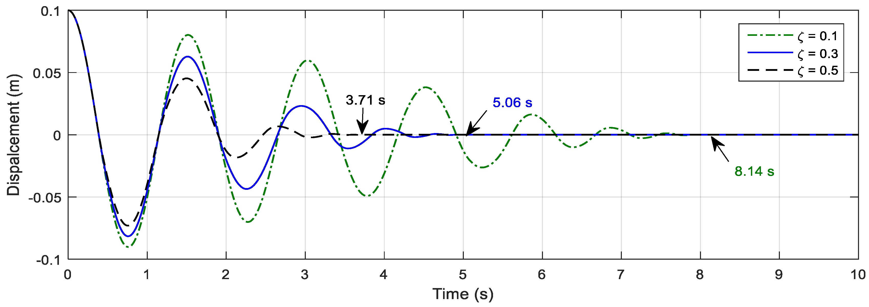
The transient responses with varying and are shown in Figure 3 and Figure 4. As shown in Figure 3a, it can be seen that the superstructure converges to the original position faster than the case without PRD for the disturbance of the initial displacement of 0.1 m. The convergence time is 24.4% for = 5 and 39.3% for , as shown in Table 2. In other words, it can be seen that as the ratio increases, it returns to the original position more quickly. Here, the meaning of = 0 is that PRD is not installed. Figure 3b shows an enlargement of Figure 3a to see the convergence properties more clearly. In the case of = 0, the system does not converge to the original position but stops at a 1.2 mm deviation, as shown in Figure 3b. This means that the rolling-type seismic isolator without PRD finds it difficult to return to the original position because of insufficient restoring force to overcome rolling frictional resistance. However, because of the increase in the restoring force of the PRD installed seismic equipment, return to the original position occurs rapidly and can be rearranged to prepare for the aftershock. As the damping coefficient of PRD increases, the ability to return to the original position improves, as shown in Figure 4. Table 2 summarizes the time taken for in situ restoration, as shown in Figure 3 and Figure 4. Therefore, through the transient response analysis, it can be seen that the RIS equipped with the PRD is superior to the RIS without the PRD in terms of the position restoring performance, and the time required for restoration can be adjusted by appropriately selecting the PRD design parameters.
To investigate the effect of PRD on the damping characteristics of the system, transient analysis with a forced initial displacement of 0.05m was carried out, and the envelope of the response was considered. In the absence of PRD ( = 0) as shown in Figure 5, the envelope representing the amplitude attenuation pattern is a straight line that is typical of friction damping. However, if PRD is present, the envelope appears as a curved line. Particularly, the amplitude of response is slowly reduced when it is larger than the width of the wedge hole, but it is rapidly reduced when it is within the width of the wedge hole. Also, the attenuation of amplitude is increased respect to k/M. Therefore, it can be seen that PRD has a function increasing the damping.
3.2. Steady-State Response and Frequency Response
To investigate the response characteristics of the seismic isolation system equipped with PRD, the steady-state response of the superstructure was analyzed when the base table had a sinusoidal disturbance. This disturbed displacement of the base table can be expressed as , where is the excitation frequency. As shown in Equations (9)–(13), the seismic response is affected by , , and . Therefore, the characteristics of the response were analyzed according to the changes of , , and .
Figure 6 compares the response of device without and with PRD for the excitations of a specific frequency; the design parameters of the isolation systems are shown in Table 1 and that of PDR are = 5 and = 0.2. The natural frequency of the system without PRD was calculated to be 0.66 Hz by Equation (15). From the numerical results shown in Figure 6a, it can be seen that the resonance frequency at 0.66 Hz corresponds to the natural frequency. The amplitude at the resonance frequency tends to become very small attenuation despite the presence of PRD. This is because as the amplitude increases due to resonance, the ratio of the width of the wedge hole to the range of motion becomes smaller, thereby reducing the effect of the PRD. Figure 6b,c show the steady-state response of the system to base excitation at , corresponding to 2 Hz and at , corresponding to 3 Hz. In Figure 6b, which shows the response curve at 2 Hz, which is three times the natural frequency, the harmonic is dominant at the resonance frequency. On the other hand, it can be confirmed that the harmonic component does not appear when the excitation frequency is 3 Hz, which is not an integral multiple of the resonance frequency as shown Figure 6c. To investigate the harmonic phenomena according to the design parameters, the influence of damping, which is controllable among parameters, is examined, and the results are shown in Figure 7. As shown in Figure 7, the harmonic phenomenon is negligible in the damping value above 0.3. Therefore, it is possible to control the harmonic phenomenon by setting an appropriate damping coefficient.
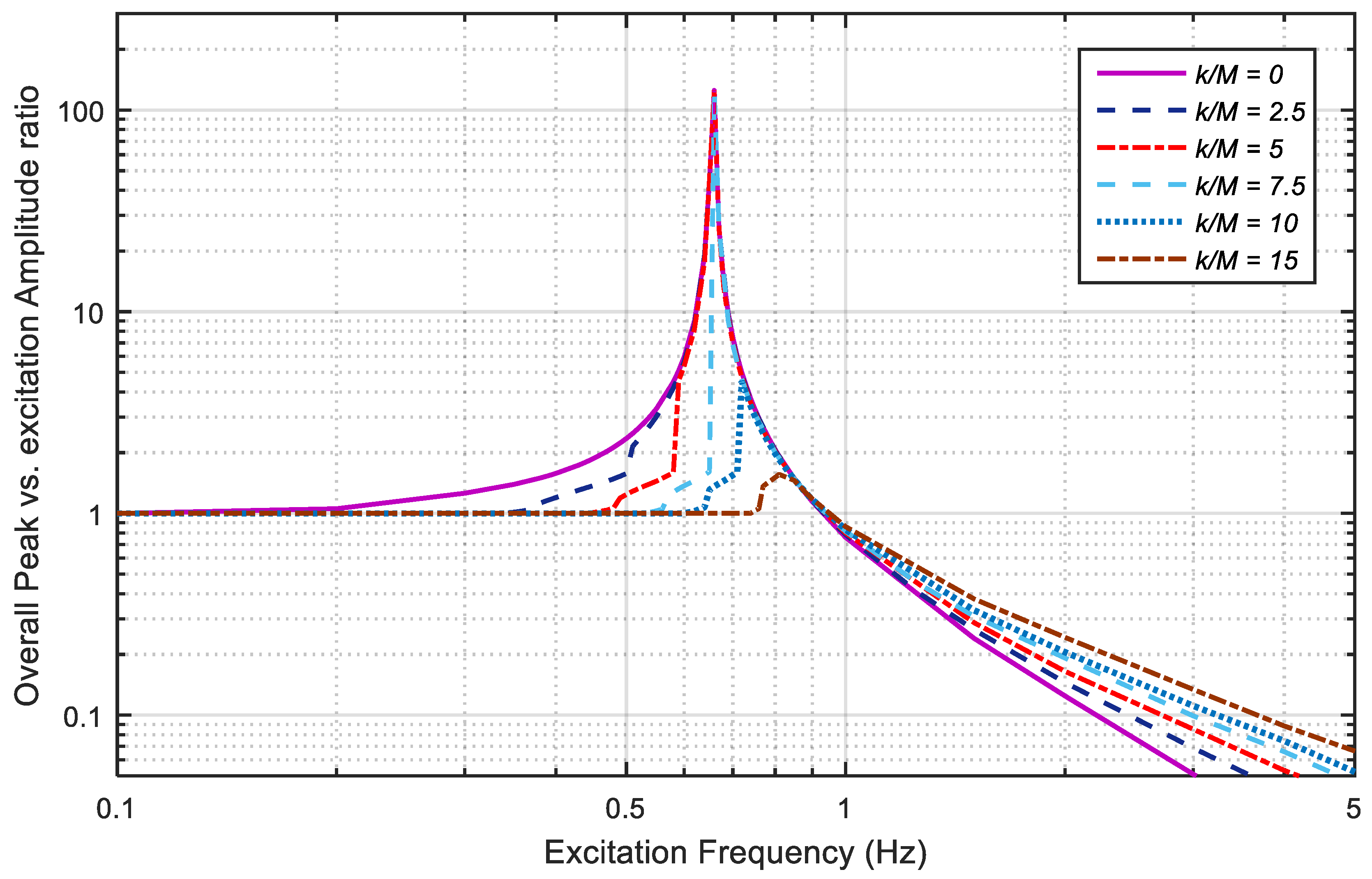
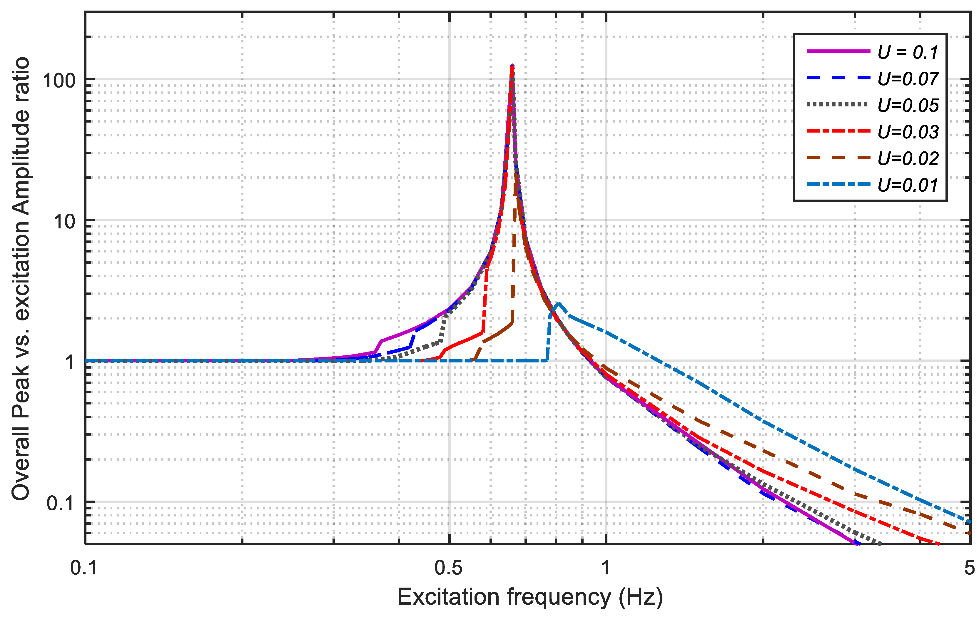
The effect of design parameters on the steady-state response for the absolute displacement of the system was investigated through base excitation at constant amplitude and frequency. As mentioned above, the displacement transmissibility ratio is defined as the ratio of the overall peak value of the steady-state response to , because the steady-state response contains harmonic components. It was obtained for various values of and , when = 0.3. The curves in Figure 8 and Figure 9 represent for and , respectively.
In Figure 8 and Figure 9, the resonant frequency appears at 0.66 Hz, and represents a typical frequency response function of a one degree of freedom system with = 1 at 0.93 Hz, which is times the resonant frequency. In the frequency range higher than 0.93 Hz, the response magnitude of the device is smaller than and decreases with increasing frequency. For frequencies below 0.93 Hz, is greater than or equal to 1, and a peak value is present. Further, in the region larger than 0.93 Hz, increases as the increases, which is equivalent to the increase of the damping value of the vibration system. As shown in Figure 9, the response of = 0.01 m shows a different frequency response characteristic, which is that is not 1 at 0.93 Hz, unlike the other values. In this case, the maximum is 2.577 at 0.81 Hz, the relative displacement is 15.7 mm (absolute displacement is 25.7 mm), and relative motion occurs only within the width of the wedge hole (±20 mm) at all excited frequencies. On the other hand, the relative movement where the spring unit moves out from the wedge hole easily occurs when the excitation amplitude or frequency are increased, as in the other cases. Therefore, in the case of = 0.01 m in Figure 9, the frequency response characteristic seems to be exceptional, unlike in other cases.
In addition, we can see in Figure 8 and Figure 9 that the jumping phenomenon occurs, wherein the relative motion increases suddenly at some frequencies. This frequency is called the jump frequency . Relative motion between the superstructure and the base table occurs as the inertia force becomes larger than the frictional force. When the relative displacement becomes larger and the amplitude becomes larger than the width of the wedge hole, the spring unit of the PRD moves away from the wedge hole. At this time, a jump phenomenon occurs, where the motion of the superstructure suddenly becomes large.
In the case of = 5 in Figure 8, relative motion starts at 0.44 Hz, and movement occurs in the wedge hole (a = 20 mm) up to 0.58 Hz, with = 1.592 (absolute displacement 47.8 mm, relative displacement 17.8 mm). At 0.59 Hz, which is larger than the excitation frequency (that is, the jump frequency of 0.58 Hz), the suddenly increases to 4.573 (absolute displacement 137.2 mm, relative displacement 107.2 mm), causing a jump in which the motion is greatly excited from the wedge hole. For = 7.5, a jump occurs at 0.71 Hz. In this case, the is 1.36 (absolute displacement: 40.8 mm, relative displacement: 10.8 mm) at the excitation frequency of 0.66 Hz, corresponding to the natural frequency of the system, and movement is limited only within the wedge hole. Therefore, large amplitude resonance does not occur. This can be applied to a design that avoids resonance.
As in Figure 9 increases, the becomes smaller. If is very large, the jump does not occur, and the transfer rate curve will be similar to that of a typical one-degree-of-freedom linear vibration system, such as = 0 (without PRD). In other words, if the amplitude of the excitation is very large, the motion moves out of the wedge hole in all the frequency domains, which means that the PRD only plays the role of damping.
Considering this jump phenomenon from the viewpoint of energy, the kinetic energy of the superstructure must be at least greater than the potential energy of the PRD spring. That is, the necessary condition of the frequency at which the jump will occur can be expressed by the following equation.
From Equations (16) and (17), it can be seen that is proportional to and inversely proportional to . Figure 10 and Figure 11 show the obtained in Figure 8 and Figure 9, and the correlation of the design parameters and , respectively. The result of Figure 10 shows that is linearly proportional to , as shown in Equations (16) and (17), and the correlation is = 0.999. Figure 11 also shows that the and are inversely proportional to each other. The changes according to the values of the design parameters, as shown in Figure 8 and Figure 9. Therefore, it is possible to design a rolling type seismic isolation system to avoid the resonance frequency, according to the selection of design factors, and it is important to set an appropriate damping coefficient.
3.3. System Response Analysis for El Centro Earthquake Waveform
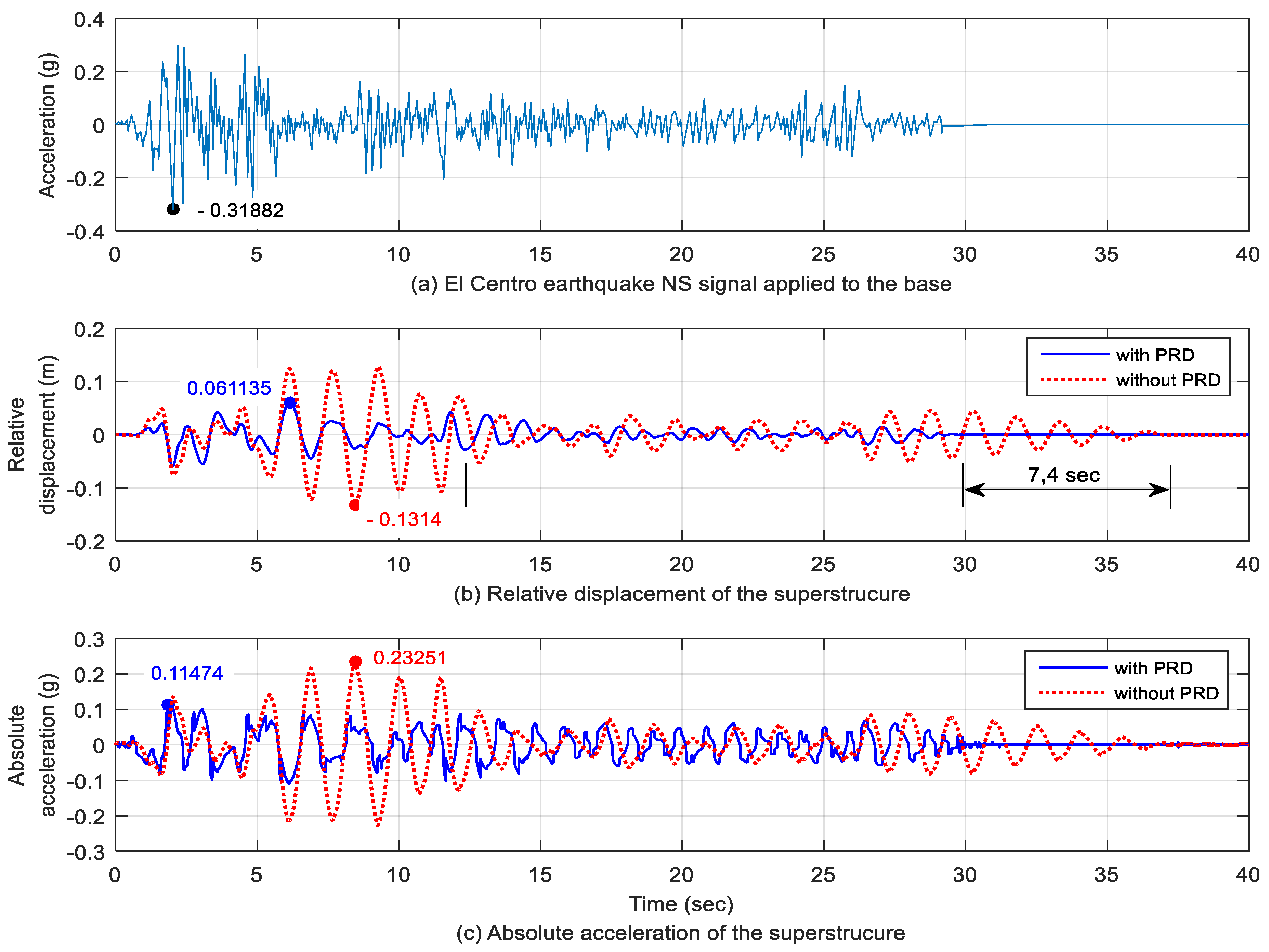
To investigate the performance of seismic isolation devices, the El Centro earthquake waveform was used, as shown in Figure 12a. When this seismic wave excited a base table, Figure 12b,c show the relative displacements to the base table and the absolute acceleration of the superstructure, respectively. The earthquake response of the isolator without PRD is also shown.
As shown in Figure 12b, the maximum relative displacement decreased to about that of the device without PRD, and returned to its original position approximately 7.4 s faster. Figure 12c shows that the maximum accelerations of the El Centro earthquake, the seismic system with PRD, and that without PRD are 0.319 g, 0.115 g, and 0.233 g, respectively. From Table 3, the maximum acceleration (0.115 g) of the superstructure of the isolation device with PRD was reduced by approximately 64% (▼0.204 g) compared with the maximum acceleration of the base excitation (0.319 g). On the other hand, in the case of the isolator without PRD, the acceleration reduction rate was 27% (▼0.086 g). Therefore, it was found that the PRD is effective for acceleration control and the position restoration ability is also excellent.
4. Conclusions
Mathematical modeling and numerical analysis were carried out to analyze the rolling bearing seismic isolation system equipped with PRD, and the results of the analysis of the equipment with and without PRD were compared. The following conclusions were obtained.
- (1)
- The PRD is an effective device to control the deviation of the original position and stop position after disturbance of the seismic isolation system, and to return quickly to the home position. Further, it is expected to solve the disadvantages of a general rolling type seismic isolation system.
- (2)
- The frequency response characteristics of the seismic isolation system equipped with PRD show that the relative displacement of the upper and lower parts and the magnitude of the response rise sharply at a specific frequency, depending on the magnitude of the spring–mass ratio and the amplitude of the excitation. It can be seen that the resonance can be avoided by controlling the design parameters because the jump frequency at which the response amplitude increases sharply is proportional to the stiffness to mass ratio and inversely proportional to the excitation amplitude .
- (3)
- The response characteristics of the rolling-type seismic system have been determined. It was found that the harmonic characteristics at the excitation frequency of an integral multiple of the resonant frequency appear, and that they can be controlled by the damping value.
- (4)
- When the El Centro earthquake excitation is applied, the PRD has good vibration damping effects, which reduce the maximum acceleration. Further, the relative displacement response is small, so the stroke of the seismic table can be designed to be small.
From the above, we can conclude that the PRD system can improve the performance of the isolation device for restoring the original position and resonance avoidance. In addition, the rolling type seismic isolation system could investigate the nonlinear characteristics, which is the phenomenon of spikes at specific frequencies and of harmonics. This phenomenon can be controlled by the ratio of mass to stiffness and the damping coefficient. Therefore, the PRD system also can be designed to quickly converge and restore its original position and to avoid resonance phenomena. Additionally, we suggest that the PRD system could be a useful device for improving the performance of the seismic isolation system. In the future a theoretical study of harmonics will be carried out.
Author Contributions
All authors discussed and agreed on the idea and had equal scientific contribution and contributed to the writing. S.C.H. contributed to the establishment of the equation of motion, the numerical programing and simulation, analysis of results, composition, and organization. D.-J.H. contributed to the partially numerical analysis, discussion, and analysis of results, and reviewed and improved the manuscript. All authors have read and approved the final manuscript.
Funding
This research was carried out without external funding.
Conflicts of Interest
The authors declare no conflicts of interest.
Nomenclature
| radius of the concave surface of the base table | |
| radius of the roller | |
| displacement of the base table | |
| relative horizontal displacements of the superstructure | |
| absolute horizontal displacements of the superstructure | |
| vertical displacement | |
| total mass of the superstructure | |
| friction coefficient of the wedge hole surface | |
| ratio of the rolling resistant coefficient to the roller radius | |
| half width of the wedge hole | |
| b | height of the wedge hole |
| compression displacement for preload | |
| spring constant of the PRD | |
| damping coefficient of the PRD | |
| damping ratio of PRD | |
| natural frequency | |
| stiffness to mass ratio | |
| excitation amplitude or exciting displacement amplitude | |
| excitation frequency | |
| fp | jump frequency |
| displacement transmissibility ratio (overall peak vs. excitation amplitude) |
References
- Esfeh, M.A.; Caldera, H.J.; Heshami, S.; Moshahedi, N.; Wirasinghe, S.C. The severity of earthquake events-statistical analysis and classfication. Int. J. Urban Sci. 2016, 20, 4–24. [Google Scholar] [CrossRef]
- Girish, M.; Pranesh, M. Sliding Isolation Systems: State-of-the-Art Review. IOSR-JMCE 2013, 6, 30–35. [Google Scholar]
- Girish, M.; Pranesh, M. Comparative Study of Sliding Isolation Systems for Near-Fault Ground Motion. Int. J. Inf. & Futuristic Res. 2014, 2, 1154–1168. [Google Scholar]
- Tsai, C.S. Advanced base isolation systems for light weight equipments. In Earthquake Resistant Structures–Design, Assessment and Rehabilitation; In-Tech: Guangdong, China, 2012; pp. 79–130. [Google Scholar]
- Hosseini, M.; Kangarloo, K. Introducing Orthogonal Roller Pairs as an effective isolating system for low rise buildings. In Seismic Control. System; WIT Press: London, UK, 2013; pp. 65–76. [Google Scholar]
- Lu, Z.; Chen, X.Y.; Zhou, Y. An equivalent method for optimization of particle tuned mass damper based on experimental parametric study. J. Sound Vib. 2018, 419, 571–584. [Google Scholar] [CrossRef]
- Dai, K.S.; Wang, J.Z.; Mao, R.F.; Lu, Z.; Chen, S.E. Experimental investigation on dynamic characterization and seismic control performance of a TLPD system. Struct. Des. Tall Spec. Build. 2016, 26, e1350. [Google Scholar] [CrossRef]
- Lu, Z.; Chen, X.Y.; Lu, X.L.; Yang, Z. Shaking table test and numerical simulation of an RC frame-core tube structure for earthquake-induced collapse. Earthquake Eng. Struct. Dyn. 2016, 45, 1537–1556. [Google Scholar] [CrossRef]
- Muhamad, F.I.; Kang, H.S.; Lee, K.Q.; Siow, C.L. Experimental analysis on variable stiffness and variable damping device. 2nd Multi. Conf. Mech. Eng. 2017, 1, 269–277. [Google Scholar]
- Hu, Y.; Liu, L.; Rahimi, S. Seismic Vibration Control of 3D Steel Frames with Irregular Plans Using Eccentrically Placed MR Damper. Sustainability 2017, 9, 1255. [Google Scholar] [CrossRef]
- Shin, Z.; Cheng, Z.; Xiang, H. Seismic isolation foundations with effective attenuation zones. Int. J. Soil Dyn. Earthquake Eng. 2014, 57, 143–151. [Google Scholar]
- Castaldo, P.; Palazzo, B.; Vecchia, P.D. Seismic reliability of base-isolated structures with friction pendulum bearings. Eng. Struct. 2015, 95, 80–93. [Google Scholar] [CrossRef]
- Kanyilmaz, A.; Castiglioni, C.A. Reducing the seismic vulnerability of existing elevated silos by means of base isolation devices. Eng. Struct. 2017, 143, 477–497. [Google Scholar] [CrossRef]
- Lin, T.W.; Chern, C.C.; Hone, C.C. Experimental study of base isolation by free rolling rods. Earthquake Eng. Struct. Dyn. 1995, 24, 1645–1650. [Google Scholar] [CrossRef]
- Lin, T.W.; Hone, C.C. Base isolation by free rolling rods under basement. Earthquake Eng. Struct. Dyn. 1993, 22, 261–273. [Google Scholar] [CrossRef]
- Mosleh, A.; Rodrigues, H.; Varum, H.; Costa, A.; Arêde, A. Seismic behavior of RC building structures designed according to current codes. Structures 2016, 7, 1–13. [Google Scholar] [CrossRef]
- Mosleh, A.; Varum, H.; Jara, J.; Razzaghi, M.S. Development of fragility curves for RC bridges subjected to reverse and strike-slip seismic sources. Eng. Struct. 2016, 11, 517–538. [Google Scholar] [CrossRef]
- Tsai, M.H.; Wu, S.Y.; Chang, K.C.; Lee, G.C. Shaking table tests of a scale bridge model with rolling-type seismic isolation bearings. Eng. Struct. 2007, 29, 694–704. [Google Scholar] [CrossRef]
- Harvey, P.S., Jr.; Gavin, H.P. The nonholonomic and chaotic nature of a rolling isolation system. J. Sound Vib. 2013, 332, 3535–3551. [Google Scholar] [CrossRef]
- Krishnamoorthy, A. Seismic Control of Continuous Bridges Using Variable Radius Friction Pendulum Systems and Viscous Fluid Dampers. Int. J. Acoust. Vibr. 2015, 20, 24–60. [Google Scholar] [CrossRef]
- Krishnamoorthy, A. Variable curvature pendulum isolator and viscous fluid damper for seismic isolation of structures. Int. J. Vibr. Control 2011, 17, 1779–1790. [Google Scholar] [CrossRef]
- Krishnamoorthy, A. Seismic isolation of bridges using variable frequency and variable friction pendulum isolator system. Struct. Eng. Int. 2010, 20, 178–184. [Google Scholar] [CrossRef]
- Pranesh, M.; Sinha, R. VFPI: An isolation device for aseismic design. Earthquake Eng. Struct. Dyn. 2000, 29, 603–627. [Google Scholar] [CrossRef]
- Tsai, C.S.; Chiang, T.C.; Chen, B.J. Finite element formulations and theoretical study for variable curvature friction pendulum system. Eng. Struct. 2003, 25, 1719–1730. [Google Scholar] [CrossRef]
- Ghidelli, M.; Sebastiani, M.; Johanns, K.E.; Pharr, G.M. Effects of indenter angle on micro-scale fracture toughness measurement by pillar splitting. J. Am. Ceram. Soc. 2017, 100, 5731–5738. [Google Scholar] [CrossRef]
- Gu, L.X.; Xu, Z.Y.; Liu, Z.F. Effect of the Fracture Toughness of Materials (Kc) on Fatigue Crack Propagation Rate. Adv. Mater. Res. 2012, 594–597, 1005–1008. [Google Scholar] [CrossRef]
- Kotzalas, M.N.; Harris, T.A. Fatigue Failure and Ball Bearing Friction. Tribol. Trans. 2008, 43, 137–143. [Google Scholar] [CrossRef]
- Iemura, H.; Miyamoto, A.; Akahashi, Y. Influence of failure of steel bearings on damage modes of bridges under strong Earthquake motion. J. Struct. Eng. 1998, 44, 659–666. [Google Scholar]
- Hibbeler, R.C.; Schiavone, P.; Yap, K.B. Chapter 8. In Mechanics for Engineers: Statics; Pearson: London, UK, 2015. [Google Scholar]
Figure 1.
Model of rolling-type isolator with the position restoring device (PRD).

Figure 2.
Free body diagram of the isolator.

Figure 3.
Transient responses of the superstructure according to change of in case of .

Figure 4.
Transient responses of the superstructure according to change of in case of .

Figure 5.
Transient response and envelope for the seismic isolation system (RIS) with PRD (initial displacement = 0.05 mm, and ).
Figure 5.
Transient response and envelope for the seismic isolation system (RIS) with PRD (initial displacement = 0.05 mm, and ).
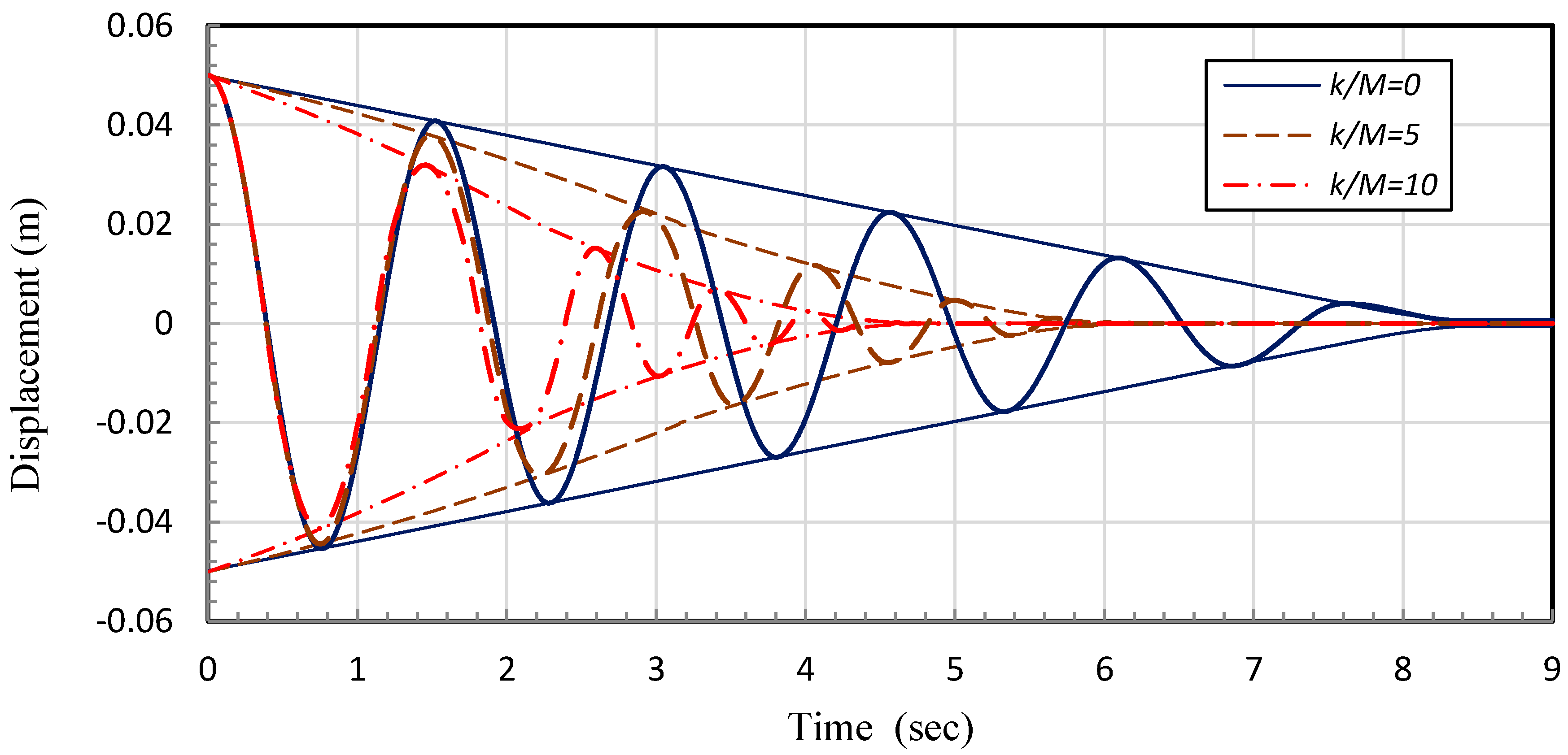
Figure 6.
Steady-state response to harmonic excitation under and .
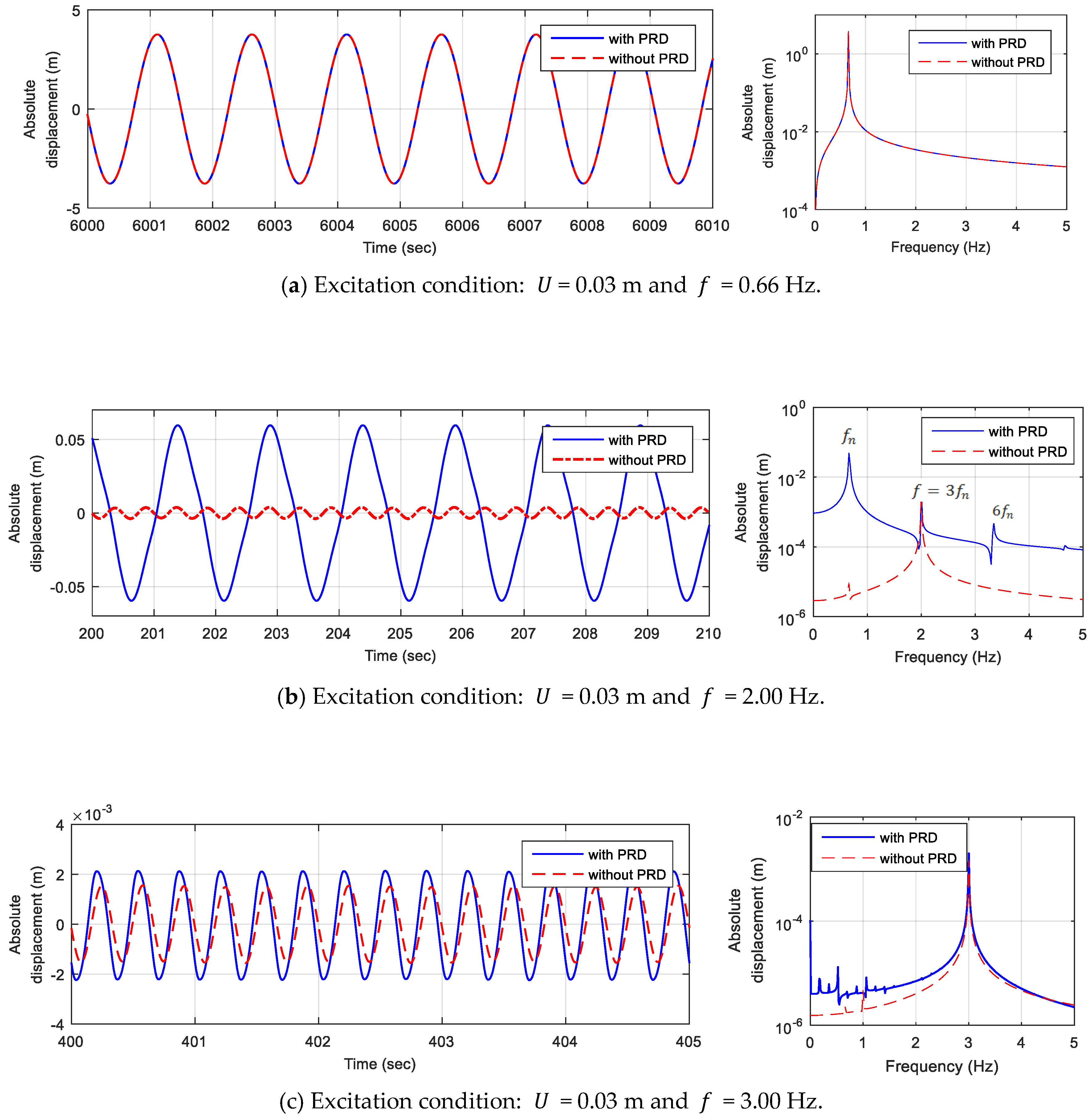
Figure 7.
The change of harmonic response according to the change of damping coefficient when m, Hz and .
Figure 7.
The change of harmonic response according to the change of damping coefficient when m, Hz and .

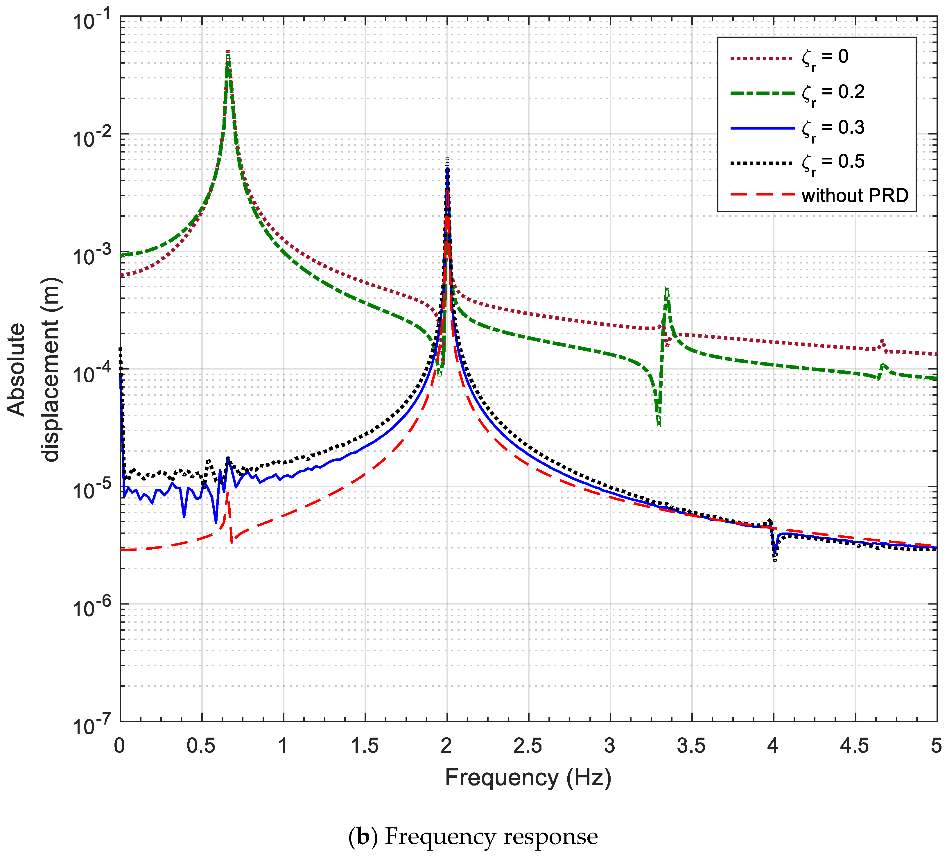
Figure 8.
Overall response vs. excitation amplitude ratio according to the parameter in case of and

Figure 9.
Overall response vs. excitation amplitude ratio according to the amplitude in case of and .
Figure 9.
Overall response vs. excitation amplitude ratio according to the amplitude in case of and .

Figure 10.
Correlation between the frequency and the parameter .
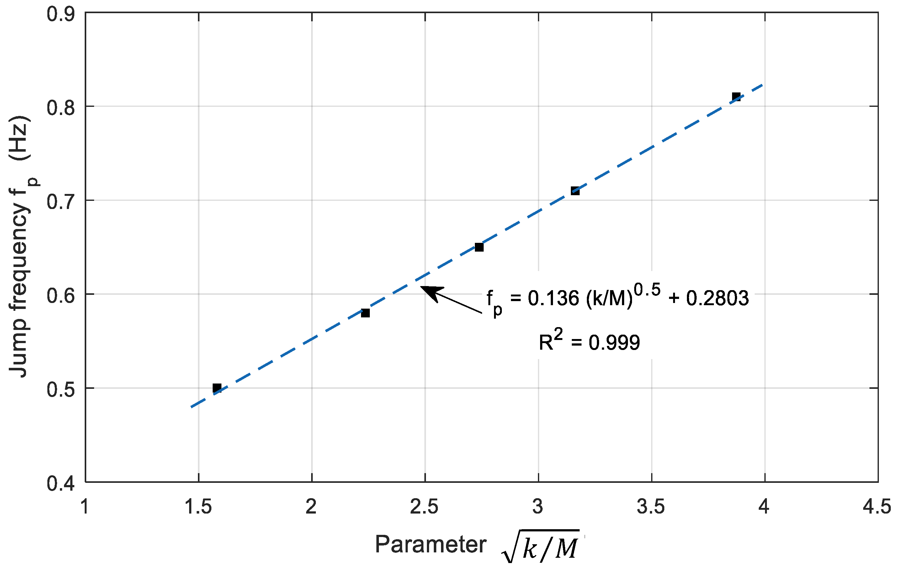
Figure 11.
Correlation between the frequency and the amplitude U.
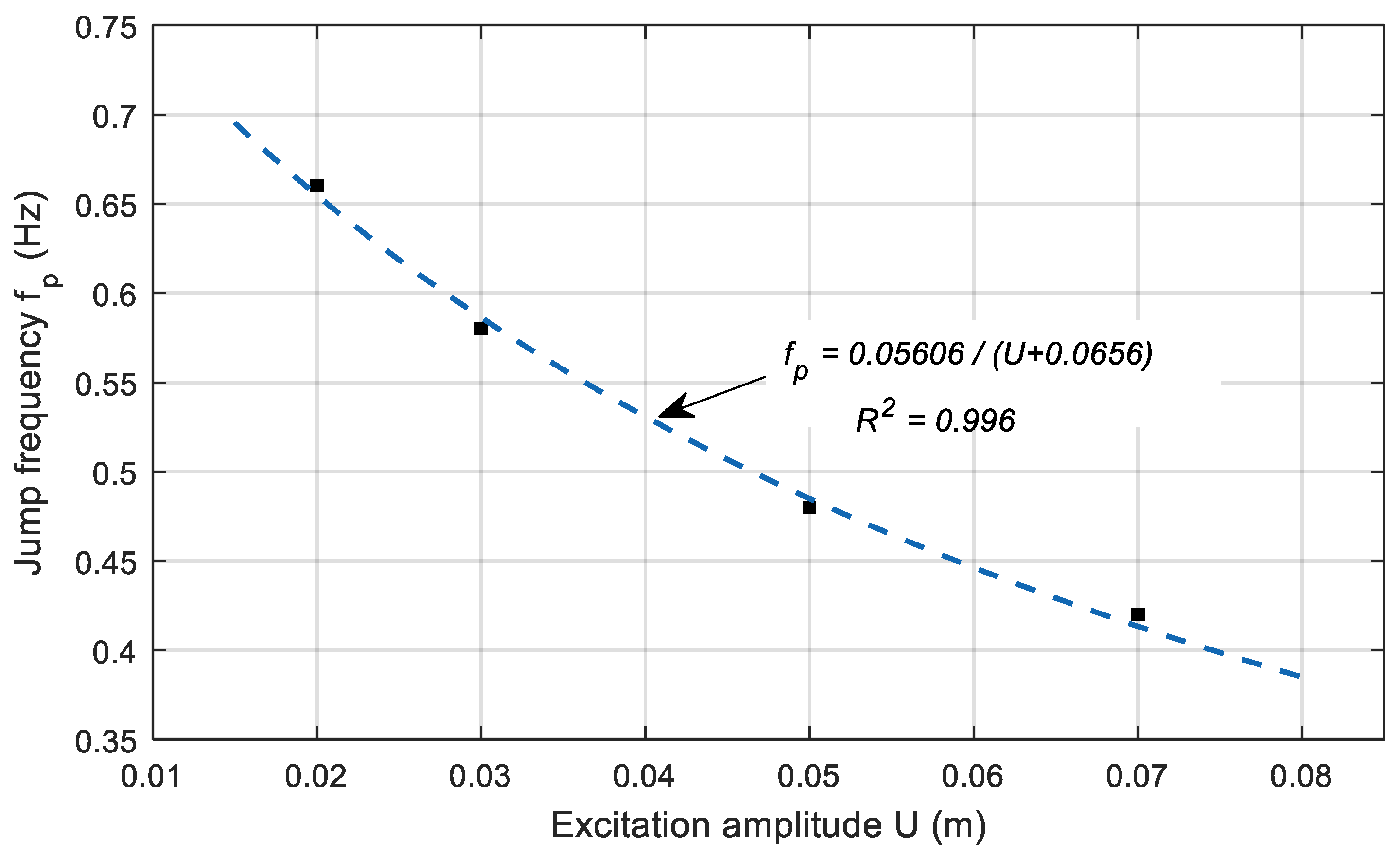
Figure 12.
Responses of the system to earthquake excitation in case of and .


Table 1.
Main dimensions and parameters.
| Parameters | Dimensions |
|---|---|
| 200 kg | |
| 600 mm | |
| 25 mm | |
| 0–2 kN/m | |
| 30 mm | |
| 0–0.5 | |
| 20 mm | |
| 20 mm | |
| 0.2 | |
| [29] | 0.004 |
Table 2.
Summary of transient analysis result (▼: Decease).
| The Ratio of | 0 (without PRD) | 5 | 10 |
|---|---|---|---|
| Time Taken to Return (s) | 16.6 | 12.55 (▼23.4%) | 10.05 (▼39.3%) |
| Offset (mm) | 1.2 | - | - |
| Damping Ratio | 0 | 0.3 | 0.5 |
| Time Taken to Return (s) | 8.14 | 5.06 (▼37.8%) | 3.71 (▼54.4%) |
Table 3.
Maximum values of seismic responses.
| El Centro Earthquake | Isolator with PRD | Isolator without PRD | |
|---|---|---|---|
| Maximum Relative Displacement | - | 6.11 cm | 13.14 cm |
| Maximum Absolute Acceleration | 0.319 g | 0.115 g (▼0.204 g) | 0.233 g (▼0.086 g) |
© 2018 by the authors. Licensee MDPI, Basel, Switzerland. This article is an open access article distributed under the terms and conditions of the Creative Commons Attribution (CC BY) license (http://creativecommons.org/licenses/by/4.0/).
Share and Cite
MDPI and ACS Style
Hong, S.C.; Hur, D.-J. Dynamic Behavior of a Simple Rolling Seismic Isolator with a Position Restoring Device. Appl. Sci. 2018, 8, 1910. https://doi.org/10.3390/app8101910
AMA Style
Hong SC, Hur D-J. Dynamic Behavior of a Simple Rolling Seismic Isolator with a Position Restoring Device. Applied Sciences. 2018; 8(10):1910. https://doi.org/10.3390/app8101910
Chicago/Turabian StyleHong, Sung Chul, and Deog-Jae Hur. 2018. "Dynamic Behavior of a Simple Rolling Seismic Isolator with a Position Restoring Device" Applied Sciences 8, no. 10: 1910. https://doi.org/10.3390/app8101910
Note that from the first issue of 2016, this journal uses article numbers instead of page numbers. See further details here.