Article

Simulation of Cyclic Deformation Behavior of Selective Laser Melted and Hybrid-Manufactured Aluminum Alloys Using the Phase-Field Method

1
Department of Materials Test Engineering (WPT), TU Dortmund University, 44227 Dortmund, Germany
2
Institute of Mechanics (IOM), TU Dortmund University, 44227 Dortmund, Germany
*
Author to whom correspondence should be addressed.
Appl. Sci. 2018, 8(10), 1948; https://doi.org/10.3390/app8101948
Submission received: 2 October 2018 / Revised: 11 October 2018 / Accepted: 11 October 2018 / Published: 16 October 2018
(This article belongs to the Special Issue Fatigue Damage of Additively Manufactured Parts)

Abstract

:
Selective laser melting process has already been developed for many metallic materials, including steel, aluminum, and titanium. The quasistatic properties of these materials have been found to be comparable or even better than their conventionally-manufactured counterparts; however, for their reliable applications in operational components, their fatigue behavior plays a critical role, which is dominated by several process-related features, like surface roughness, remnant porosity, microstructure, and residual stresses, which are controlled by the processing features, like imparted energy density to the material, its corresponding solidification behavior, the cooling rate in the process, as well as post-processing treatments. This study investigates the influence of these parameters on the cyclic deformation behavior of selective laser melted as well as hybrid-manufactured aluminum alloys. The corresponding microstructural features and porosity conditions are evaluated for developing correlations between the process conditions to microstructure, the deformation behavior, and the corresponding fatigue lives. From the numerical point of view, damage development with respect to process-induced cyclic deformation behavior is assessed by the phase-field method, which has been identified as an appropriate method for the determination of fatigue life at the respective applied stress levels. Fatigue strength of SLM-processed parts is found better than their cast counterparts, while hybridization has further increased fatigue strength. No effect of test frequency on the fatigue life could be established.

1. Introduction

Among different additive manufacturing (AM) techniques ranging from partial sintering to full melting, selective laser melting (SLM) process aims at the full melting of the powder material spread on the base platform by using a focused laser beam. The development side of the process can now be considered at a mature stage such that it can result in almost fully-dense components, at least for some of the materials, like steel, aluminum, titanium, as well as some of the superalloys [1,2,3]. Imparted energy density is the dominant factor in determining the resulting part quality in terms of relative density; however, for the components to remain functionally stable under mechanical loading, these parameters have to be investigated carefully so that their influence on the part porosity, microstructure, as well as residual stresses can be considered in designing functionally reliable components. A brief synopsis is given below about the most important aspects of the process, followed by the part properties that are specific to Al-Si alloys manufactured by the SLM process.
Certain phenomena involved in the SLM process have to be understood in detail with regard to the process conditions, their behavior during the process, and their corresponding part characteristics. One of these is the balling effect, which is observed in the process due to the shrinkage of the melt pool. Uncontrolled balling is detrimental to the SLM parts in terms of its tendency to pore formation. For attenuation of this effect, factors, like oxygen content, laser power, scan speed, and hatch distance need to be controlled for obtaining the optimal feedstock wettability [4,5]. Another important aspect of the SLM process thatcan significantly affect the resulting part is the melt pool condition affecting the local microstructural features. The role of scanning strategy in influencing a gradient microstructure using electron beam melting technology was investigated. The technology was introduced under the term “ghost beam scan strategy” [6]. Fine microstructures, generally obtained in the SLM process, are due to short exposure of laser energy to the feedstock powder and the consequential elevated thermal gradients giving rise to thermal stresses in the parts. A mixed microstructure, fine and coarse, depending on the local exposure, is obtained, which is generally a metastable microstructure, especially in Al-Si alloys, which can be changed by post-process exposure to temperature. Al-Si system results in dendritic microstructure in SLM—generally fine dendrites thatare coarsened at double-melt regions due to increased exposure to laser beam. For such material class, the role of temperature is important due to its effect on the solubility of Si in the matrix, as well as its rejection in the matrix. The rejected Si particles can act as a reinforcement of the matrix, but they can also be a source of crack initiation when they are large in size and inhomogeneous in morphology making the resulting material as brittle and susceptible to unpredictable failure under fatigue loading [7,8].
Identification and controlling the thermally-induced residual stresses is a critical aspect when SLM components are to be employed in fatigue applications. Several SLM attributes drive the formation of these stresses, the time-dependent exposure being the most important one where the cooling rate in SLM creates waves of thermal expansion and contraction. Longitudinal scanning strategy results in the anisotropic development of thermal stresses, which can be controlled by following the so-called island scanning, which reduces the melt pool anisotropy [9]. Base platform can also be critical in controlling the thermal gradients where its thickness, as well as temperature, determines the resulting cooling rate. Pre-heating the platform can reduce these gradients and weaken the development of thermal stresses [10,11], since current research proved that a gradient of microstructure and properties could be induced on a scale of 100 µm [12].
Many researchers have investigated the quasistatic mechanical behavior of SLM-processed alloys, and it is found that their quasistatic tensile strength is comparable to their cast or wrought counterparts, while surpassing in some instances, e.g., [10,13,14]. The maintenance or increase in tensile strength is attributed to several factors, with the fine microstructure being the most dominant one for all of the materials. This feature has an accompanying aspect of a decrease in ductility due to a decrease in microstructural size.
The fatigue behavior of SLM parts has been intensively investigated in the last few years. It has been found that the fatigue mechanisms in these parts are significantly influenced by the process-incited aspects, like remnant porosity, microstructure, roughness, and residual stresses. The few existing studies on fatigue behavior of SLM materials—Ti-alloys [15,16], Al alloys [1,17,18], and steels [19,20] have shown that the fatigue strength of SLM-processed parts in their as-built condition is far inferior to their surface-finished parts, as the surface roughness of these parts usually lie in the range of Rz = 30 to 50 µm. Process-induced differences in microstructure and properties have been investigated, as, for example, the influence of application of laser beam or electron beam melting on properties of Ti-6Al-4V [21,22]. Such high roughness initiates the surface crack at an early stage of fatigue life. However, after post-process surface finishing of these parts, their fatigue strength is, in general, comparable to that of their wrought counterparts. But, the reliability of fatigue strength is found to be low due to multiple fatigue mechanisms in these materials.
The most influencing factor related to fatigue mechanisms is remnant porosity. Though the SLM parts have generally higher than 99.5% relative density, a small fraction of the remnant porosity drives the mechanism of fatigue crack initiation, and, therefore, the fatigue failure. In the absence of significant porosity near the part contour, surface weakness plays the dominant role in causing a fatigue crack initiation from the surface [20,23]. In the presence of critical defects in the core, these defects are generally responsible for fatigue crack initiation, and the intensity of their deteriorating effect on fatigue depends on their location relative to the component boundary. Near the contour, pores are more influential in initiating a fatigue crack, and their propagation, until they reach the component boundary, is usually very abrupt, resulting in much-reduced fatigue life. Pores of similar size, found far from the part contour, can still survive until the fatigue crack is initiated and the part will endure longer life [15,23,24].
The microstructure is usually the most important factor for determination of the fatigue behavior of parts; however, its role is diminished in SLM parts under the presence of porosity. Once remnant porosity is controlled, it is the next process-specific feature influencing the fatigue mechanisms. The ultra-fine microstructure that was obtained in the SLM process poses impediment to the movement of dislocations which creates resistance to fatigue crack initiation and make these parts endure longer under fatigue loading; however, this behavior can depend on the region of fatigue life under consideration, as the grain size generally have a contrasting effect on crack initiation and crack growth. The process-specific thermal evolution influences the microstructural features, which, in turn, have their effect on crack initiation and crack propagation phases [25,26]. For laboratory testing of specimens, the crack initiation phase is dominant in high cycle fatigue (HCF) at lower applied stresses and very high cycle fatigue (VHCF) regions at very low stresses, even below the conventional fatigue limit, and the role of porosity and microstructure and their interaction effects should be deeply investigated. Residual stresses in the SLM parts are another important factor in shaping the mechanisms of fatigue damage. Their role needs to be investigated together with porosity and microstructure to determine the extent of their impact on fatigue strength as well as fatigue scatter.
Another aspect of this study is the investigation of fatigue mechanisms in the VHCF range. An increasing number of components are now subjected to fatigue loading higher than the conventional fatigue-limit or the endurance limit, e.g., for aluminum alloys. The previous design criterion used these limits for structural designs, but the latest research in the VHCF region has questioned the existence of these limits [27]. It has been found that the materials continue to fail when they are subjected to stresses lower than the conventional limits, with increasing number of cycles. The conventional fatigue limit can be envisaged only as an outset to persistent slip bands (PSBs) or termed as plastic strain fatigue limit. With the availability of the high-frequency fatigue machines, e.g., ultrasonic fatigue testing system, the investigation of the fatigue mechanism in the VHCF region is important to investigate the fatigue mechanisms in that region as well as to have more reliability in designing structures. For fcc materials, like Al, where fatigue limit is non-existing, the influence of microstructural features and porosity in VHCF range and their local interactions are important to be understood [28,29,30]. Additionally, an important aspect to be investigated when ultrasonic fatigue behavior comes into the discussion is the influence of the test frequency. Traditionally, fatigue testing has been performed under 50 Hz. Therefore the effect of performing fatigue tests at an ultrasonic frequency as compared to conventionally used frequency is an important research aspect. The effect of frequency in the available literature has been found material-dependent. An increase in fatigue strength at ultrasonic frequency has been reported by some researchers [31,32] for carbon steels. At the same time, no significant effect was also reported by some other researchers, e.g., [33] when tests were performed at frequencies of 150 Hz and 20 kHz. For aluminum alloys, the trend has been found similar with both types of results—significant frequency effect [34], as well as mixed effect [35] of frequency at different test temperatures. Therefore, the effect of frequency needs to be further investigated for each specific case of material, process, and test conditions.
The numerical modeling of the damage process relies on the application of the phase-field method [36,37,38]. This up-to-date approach is advantageous when compared to the traditional strategies with regard to different aspects. The latter ones assume J-integral as the driving force of the crack propagation, which does not always match the experimental observations, as J-integral vanishes in some cases although the crack propagation is expected. On the contrary, a variational free-discontinuity formulation enables the simulation of crack evolution only by energy minimization with respect to the crack geometry and displacements [39,40]. In this approach, the phase-field variable taking the values in the range [0,1] is introduced to describe damage state. The simulation of fatigue by using the phase-field strategy has recently started [41].
The preceding synopsis about the aspects related to SLM process parameters influencing their part and mechanical properties unfold several specific guidelines. However, the existing studies focus more on the process development side with respect to maximizing/minimizing some or the other objective criterion like porosity, microstructural development in-process and by post-process heat treatments. This study aims at developing an extended profile of processing and post-processing aspects, and their corresponding part properties, like porosity, microstructure, and residual stresses for the selected Al-Si alloy. The second part investigates the corresponding mechanical behavior of these configurations in terms of quasistatic tensile properties, HCF as well as VHCF until 1E9 cycles. VHCF has been tested for many of the functional components used in transportation industries, since they experience load cycles significantly above the previously used limit of 1E9 cycles. For ultrasonic frequency, it is important to understand the influence that the test frequency may have on the fatigue strength, which is also an issue investigated here. The influence of processing conditions on part properties as well as mechanical behavior is investigated such that to develop correlations between the process chain and the corresponding material and mechanical properties. Combination of conventional manufacturing processes together with the SLM process has been investigated to get the synergic advantages of the two processes for the integrated workstations. The experimental study is completed by numerical simulations that are based on the phase-field method and gives guidelines to manufacture the optimal hybrid components.

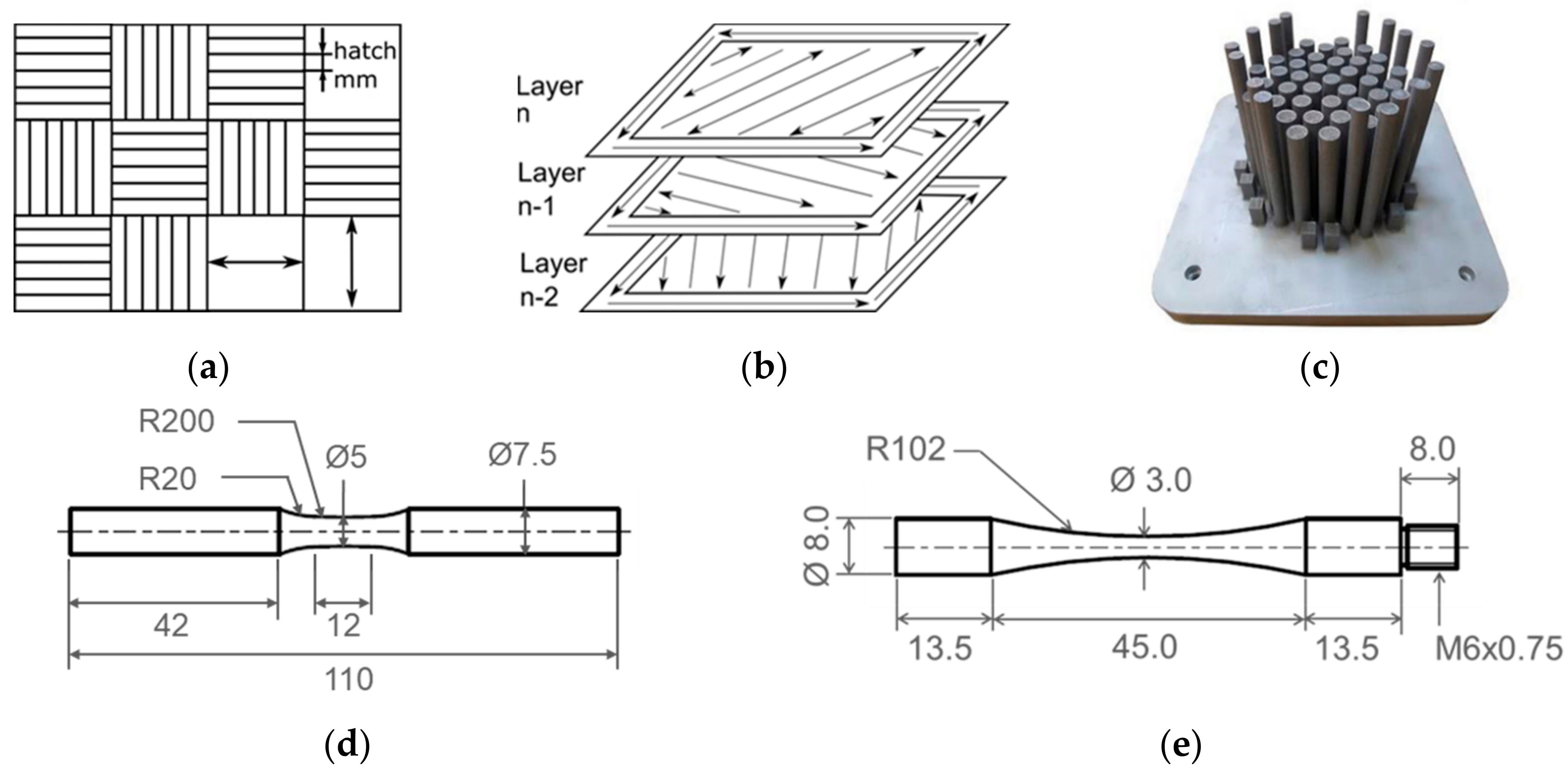
2. Materials and Methods

Five different configurations of Al-alloys were considered, as summarized in Table 1, with the material, the processing, as well as post-processing conditions. Batches A-C were manufactured completely by the SLM process using Al4047 powder. Batch A represents the as-built condition, while stress-relief at 240 °C for 2 h was performed for batch B. Batch C was manufactured while the heating platform was heated continuously at 200 °C during the processing. These in-process and post-process heat treatments were performed to understand their influence on their part characteristics as a result of changing cooling conditions in the melt pool. For investigation of integrated manufacturing feasibility, batches D and E were manufactured while taking Al7020 wrought blocks as the base platform in the SLM processing, and Al4047 was generated over it. The influence of post-process stress-relief for hybrid specimens is investigated in batch E.
Powder material for Al4047 feedstock that was produced by gas atomization was obtained from SLM Solutions with a D10-D90 diameter range of 20–63 µm. The morphology of this powder, as shown in Figure 1a, is dominated by spherical particles. The corresponding powder size distribution (PSD), as shown in Figure 1b, is relatively uniform around the mean equivalent diameter of 33 µm with a standard deviation of 6 µm. The non-existence of powder particles below 10 µm makes this powder good in flowability.
Another important aspect in powder-based AM process is the chemical composition of the used material. Table 2 shows this composition for the Al4047 alloy used in this study. The composition having a nominal value of 12 wt% Si makes the alloy eutectic, and the Si percentage together with the heating/cooling rates in the SLM process can make it a critical alloying element.
SLM processing was carried out using the machine system SLM 250HL (SLM Solutions, Luebeck, Germany) applying chessboard scanning strategy shown in Figure 2a where each chess field consisted of an edge length of 7.47 mm. Within the individual chess fields, hatch direction was altered by 90°. A rotation of 79° was employed for each layer, as shown in three layers in Figure 2b, to reduce anisotropy in the resulting material properties. The melting parameters used were: laser power of 350 W, scan speed of 930 mm/s, hatch distance of 0.19 mm, and a layer thickness of 50 µm. The same scanning strategy was used for the core and contour of the specimens, as shown in Figure 2c, as they were machined and polished before testing was carried out. The test specimens to which these cylindrical rods were converted are shown in Figure 3d for tensile and high cycle fatigue testing, and in Figure 2e for very high cycle fatigue specimens.
Cubical specimens were prepared for part surface and microstructural analysis, which were ground and subsequently polished using oxide suspension. Porosity was characterized by measuring relative density using different sections whose images, twelve for each batch, were taken at Olympus microscope (Olympus Corporation, Tokyo, Japan) and image correlation software DHS (DHS Solution, Greifenstein, Germany) was used for quantification. These embedded specimens were prepared for microstructural analysis by etching with NaOH and HNO3 and were analyzed in scanning electron microscope Tescan Mira XMU (TESCAN, Brno, Czech Republic) by EOS. The microstructural features of the eutectic alloy were measured in terms of the dendritic width. To measure the influence of processing conditions focused on cooling rate, the resulting thermal stresses were measured on the test specimens shown in Figure 2d in the gauge length. The measurement of residual stresses was performed by diffraction method Sin2Ψ and CuKα-beamand was processed afterward by intermediate Lorentz function.
Quasistatic tensile tests were performed using the test specimen shown in Figure 2d as per ISO 6892-1:2009 at a deformation rate of 1 mm/min using Instron 3369 (Norwood, MA, USA) universal testing machine with a load cell of 50 kN. The deformation during the test was measured using a 10 mm gauge length extensometer. Quasistatic tensile tests were also performed inside an X-ray computed tomography, namely Nikon XT H 160 (Nikon, Tokyo, Japan), which is integrated with 160 kV/60 W micro-focus X-ray tube. In-situ test module CT 50000-GCT-RT was integrated inside the CT chamber on the manipulator platform, as shown in Figure 3a. Displacement-controlled tests were performed at 1 mm/min, and the tests were interrupted at defined intermediate stages where the gauge length was scanned before continuing the test further. Scanning was performed at four stages, and a miniature specimen was developed, as shown in Figure 3b, to fit in the in-situ module. The scans were evaluated using the reconstruction of the scan data. These intermittent tensile tests were performed only on one batch, where batch C was selected due to its relatively more damage-tolerant behavior as compared to other configurations.
A mixed strategy was employed for the characterization of fatigue behavior of the investigated configurations. It consisted of multiple amplitude tests accompanied by measurement of material behavior during fatigue loading, and constant amplitude tests at different frequencies of 20 Hz and 20 kHz employing servohydraulic and ultrasonic fatigue testing systems, respectively. Multiple amplitude tests were performed initially for all of the configurations to have a first indication of the material behavior at different stress loadings. It was carried out by continuously increasing fatigue load, a schematic of which is shown later in Figure 8 together with the corresponding results. Plastic deformation behavior was measured by 10 mm gauge length extensometer. Irreversible fatigue damage in terms of plastic strain amplitude was measured, and the corresponding stress range was considered to be critical for further constant amplitude tests, which gave a detailed description of material behavior and the influence of processing conditions. The corresponding part characteristics were analyzed together with their fatigue response to develop process-structure-property relationships. Load increase tests and HCF tests at 20 Hz were carried out at Instron 8872 servohydraulic fatigue testing system. Batch D of hybrid configuration without post-process stress-relief, due to its low ductility, was not considered for fatigue investigations.
For the investigation of fatigue behavior in very high cycle fatigue region, ultrasonic fatigue testing system Shimadzu USF-2000A (Shimadzu, Kyoto, Japan) resonating at a frequency of 20 kHz was employed. To avoid stress-induced heating at an ultrasonic frequency, the tests were carried out at a so-called pulse:pause ratio of 50:50 where the system resonated for 200 ms and then stopped for the next 200 ms such that the deformation-induced rise in temperature remained below 10 K. All the fatigue testing was performed under fully-reversed loading.The details of the test setup can be seen in [42]. Tests at the two frequencies resulted in Woehler curves until 1E9 cycles. These Woehler curves were obtained by testing the configurations B, C, and E, which were post-processed by stress-relief treatment.
The failure mechanisms in solids are typically modeled based on sharp crack discontinuities. However, this approach suffers in situations with complex crack topologies. This drawback is eliminated by introducing a diffusive crack modeling based on a crack phase-field d, which covers values in the range [0,1], where d = 0 describes the unbroken state of the material and d = 1 the fully broken state. The model starts with the assumption for the free energy in the following form
  ψ ( ε e ,   d ) = 1 2 [ ( 1 d ) 2 + k n ] ε e :   : ε e , ε =   ε e + ε p ,  
where ε e is the elastic strain, the elasticity matrix, and k n a small constant required to achieve numerical stability in the case of a fully broken material. The additive decomposition of total strains ε into an elastic part ε e and an inelastic part ε p is a typical assumption for the small strain theory.
However, Equation (1) does not represent a full model, but it must be completed by an expression governing the evolution of the damage parameter d. In contrast to phenomenological methods, the present contribution follows a strategy where an assumption for a physically motivated dissipation potential is met [36]. According to such an approach, the phase-field d is related to the crack surface A of a crack embedded in a body B by the relationship
  A ( d ) =   B   γ ( d , d ) d V , γ ( d ,   d ) =   1 2 l d 2 +   l 2 d 2 ,  
where γ is the crack surface density, depending on the phase-field and its gradient. Miehe et al. [36] introduced the constitutive dissipation functional for a rate-independent fracture process as
  D ( d ˙ ; d ) =   B   ϕ ( d ˙ , d ˙ ; d , d ) d V , ϕ =   g c γ ˙ ( d ˙ , d ˙ ; d , d ) ,  
which satisfies a global irreversibility constraint of the crack evolution. In the above equation g c is a threshold value that is related to the critical Griffith-type fracture and ϕ is a dissipation function per unit volume. In order to cover isotropic hardening effects, an additional term k y | | ε ˙ p | | is introduced, leading to the final form of the dissipation potential
  D =   g c l d d · +   g c l · d · d ˙ + k y ε ˙ p ,   k y =   k y 0 + k h , k ˙ h = H ε ˙ p ,  
where l is the length-scale parameter and k y the current yield limit with the evolution depending on the initial yield limit k y 0 and isotropic hardening H . The full formulation additionally requires a Lagrange term stipulating the non-negativity of the damage rate.
Equation (1) corresponds to the case that both, tension and compression, affect the evolution of the damage, which is not consistent with the real physics of the process where solely the tension contributes to damage. This drawback can be eliminated by assuming an additive decomposition of the total free energy into a tension part (( ψ + ( ε + e ) ) and a compression part ( ψ ( ε e ) ) . The corresponding anisotropic energy storage function reads
  ψ ( ε e ,   d ) =   [ ( 1 d ) 2 + k n ] ψ + ( ε + e ) +   ψ ( ε e ) .  
The definition of the positive and negative part is based on the spectral decomposition of the strain tensor
  ε ± =   a = 1 3 ε a ± n a n a ,  
where the principal strains are denoted as { ε a } a = 1 3 and where the principal strain directions are denoted as { n a } a   = 1 3 . The ramp function defined as x ± [ x ± x ] / 2 separates the positive and negative entries.

3. Results and Discussions

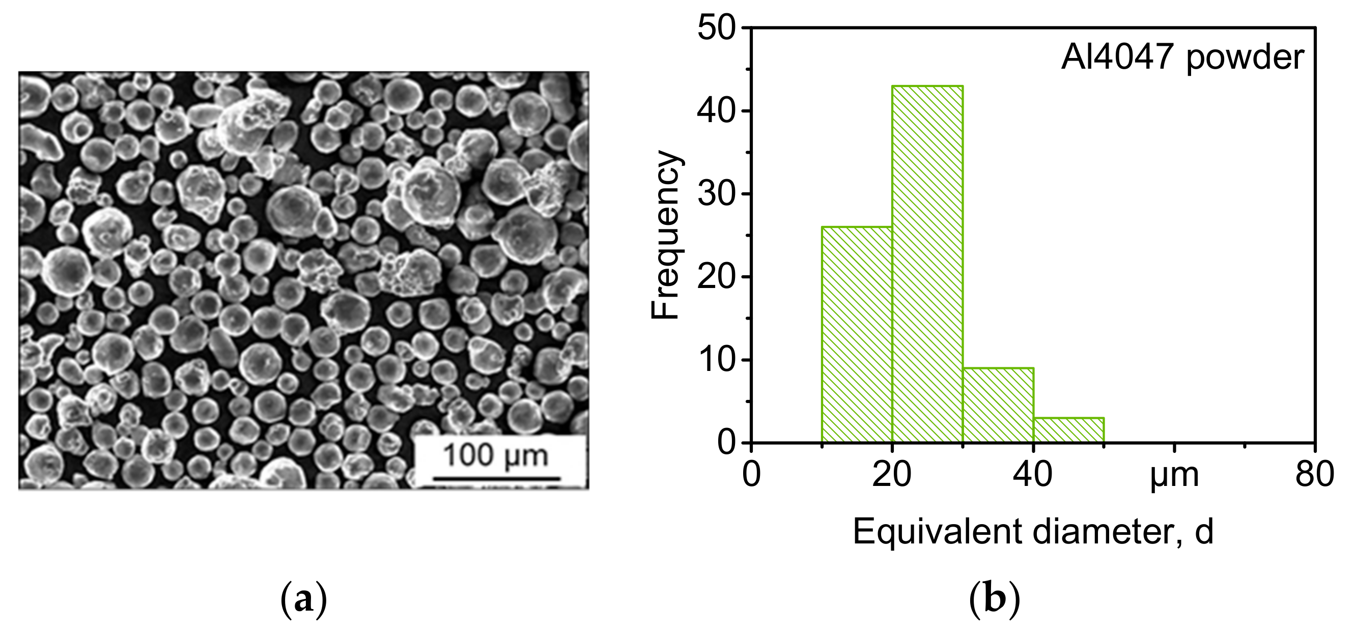
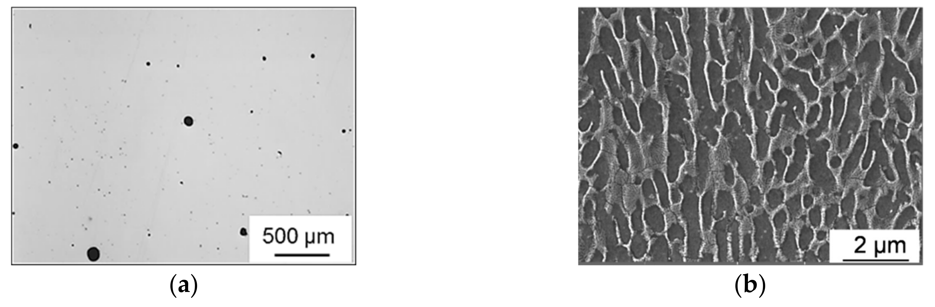
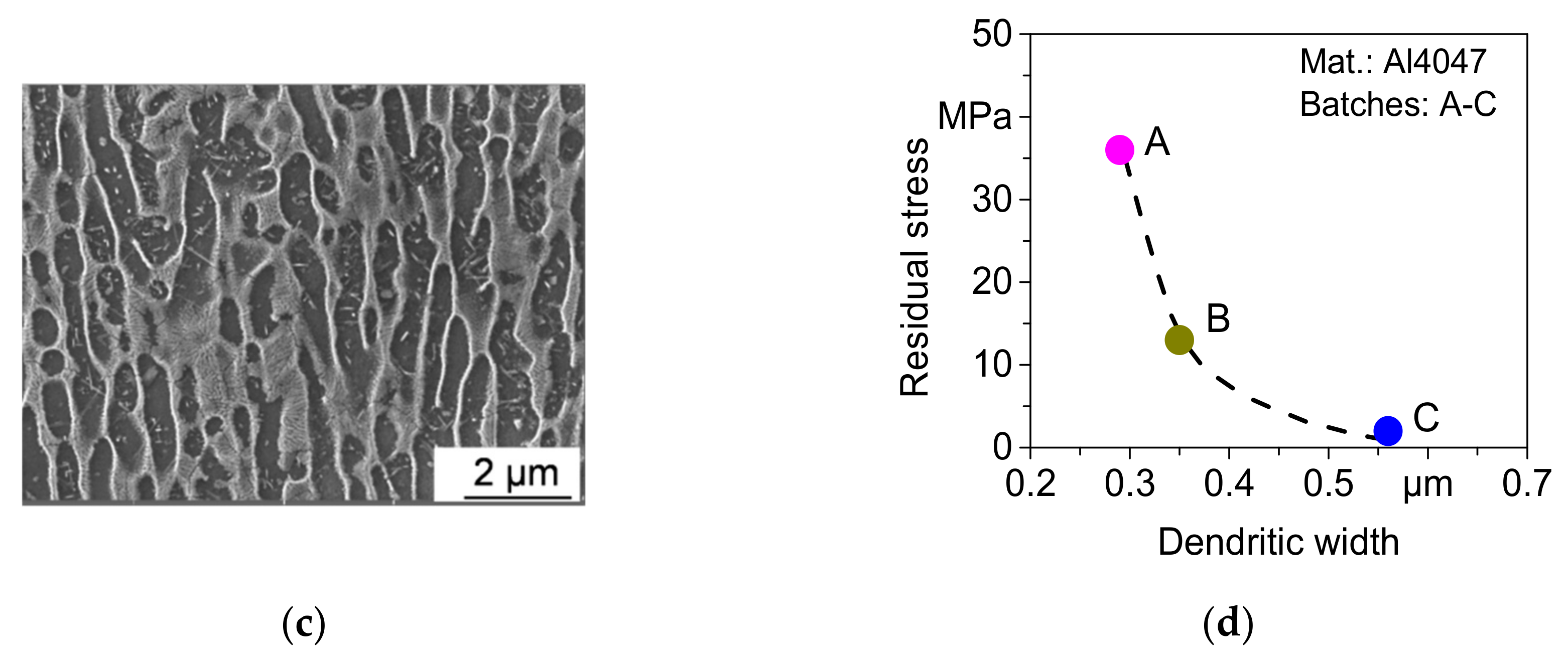
3.1. Relative Density and Microstructure

The optimized laser energy density imparted to the Al4047 powder material resulted in near fully-dense parts with a remnant porosity of less than 0.4%. These calculations were carried out only for the pure Al4047 material. An exemplary micrograph is shown in Figure 4 for batch A, the as-built condition, which shows that the dominant type of defects is the gas porosity. Table 3 quantifies the resulting percentage of remnant porosity where the as-built condition resulted in a remnant porosity of 0.26%. After post-process stress-relief, it is increased to 0.38%, which can be attributed to the extended duration of the applied temperature during the stress-relief procedure thatwould have developed an internal pressure in the pores, and a slight expansion of these pores would be possible resulting in a marginal expansion in porosity volume. Similar observations were reported in SLM processed materials in [43,44]. For the base-plate heated and stress-relieved configuration, batch C, 0.29% remnant porosity was calculated, which is less as compared to similar conditions without base plate heating, batch B. This improved relative density can be attributed to the reduced thermal gradients by heating of the base plate, thereby helping the melt pool to stabilize, increasing the density of the melt pool itself as compared to the released gases and allowing more time for these gases to escape the melt.
The microstructure of SLM-processed Al4047 alloy has been reported in the literature that it consists of ultrafine grains in terms of dendrites developed in the matrix. As the process is localized in nature, so is the microstructural development, which consists of fine and relatively coarse regions. Coarser regions are existing at the places, e.g., hatch overlaps receiving more laser energy per unit area. However, the most important aspect of microstructure observed was the average width of the dendrites in the prevalent single melt regions. The size of these dendrites was found to be dependent on the cooling rate during the process as well as on the thermal treatment after the process. Dendritic width was measured across six images for batches A–C and exemplarily shown in Figure 4b,c for the batches B and C and plotted in Figure 4d in relation to the measured residual stresses.
For the as-built condition, batch A, the average dendritic width of 0.29 µm was calculated, which increased to 0.35 µm after stress-relief treatment (batch B), and 0.56 µm for the batch manufactured with base plate heating (batch C). Though there is an increase in dendritic width after stress-relief, 0.35 mm from 0.29 µm, the increase due to base plate heating is much higher reaching to 0.56 µm. Results of residual stresses that were measured at the surface of the specimens are shown in Figure 4d as a function of the dendritic width. The as-built condition, batch A, has developed the highest value of tensile residual stress at the surface, i.e., 36 MPa. After stress-relief treatment, batch B, the residual stress reduced to 13 MPa, and the combination of base plate heating and stress-relief, batch C, resulted in a very small value of 4 MPa. These values are worth discussing based on the microstructural features, Figure 4d. The highest value of tensile residual stress of 36 MPa is observed in the batch with the least value of dendritic width, 0.29 µm, which is previously attributed to the highest thermal gradient in the SLM process. Increased dendritic width after stress-relief treatment, batch B, decreased the residual stress to 13 MPa. The combination of the two thermal processes, in-process base plate heating, and post-process stress-relief, increasing the dendritic width to 0.56µm, has decreased the accompanying residual stress value to only 4 MPa. These changes in microstructural features show the potential of controlling the thermal gradients for obtaining the required microstructure which should further be investigated for the functional grading of microstructure within the same component.

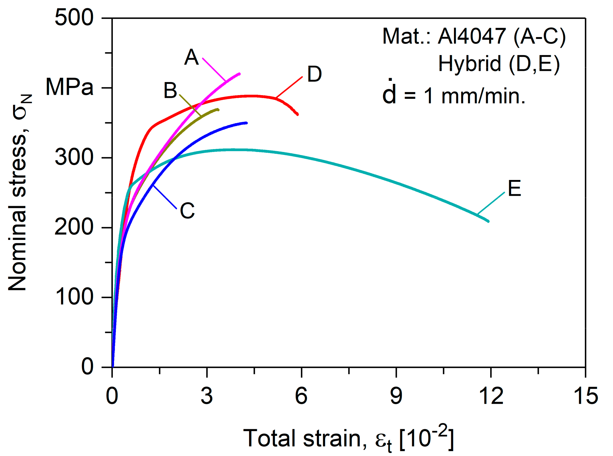
3.2. Quasistatic Behavior

The quasistatic behavior of the three conditions of the pure Al4047 parts and two hybrid batches, wrought Al7020 + SLM Al4047, is shown in the form of stress-strain curves in Figure 5. The quasistatic tensile strength of the as-built condition, batch A, has been found highest from the pure Al4047 with an ultimate tensile strength value of 418.9 ± 9.6 MPa with an accompanying total strain at fracture of 3.91 ± 0.27 [10−2]. After stress-relief treatment in batch B, the ultimate tensile strength decreased to 372.3 ± 7.2 MPa, and the corresponding fracture strain also decreased to a value of 3.41 ± 0.29 [10−2].
The combination of the two thermal treatments in batch C decreased the ultimate tensile strength further to 361.1 ± 3.4 MPa but with an increase in fracture strain to 4.05 ± 0.15 [10−2]. The stress-strain curves in Figure 5 show the influence of processing configurations on mechanical behavior. Tensile strength decreased due to stress-relief treatment as well as due to base plate heating during the process. There is a simultaneous decrease in the ultimate tensile strength and fracture strain due to post-process stress-relief; whereas, a decrease in ultimate tensile strength due to in-process base plate heating is accompanied with a corresponding increase in fracture strain. This effect can be characterized on the basis of dendritic width to Hall-Petch behavior where the microstructure is coarsened due to decreased thermal gradients, owing to base plate heating. Along with the phenomenon of grain boundary strengthening, other factors, like porosity and Si solubility, play their own role. Increased porosity decreases the tensile strength as well as fracture strain. Si having a very low solubility of 1.65% at the eutectic temperature is reduced to only 0.06% when temperature reduces to 200 °C; however, the Si solubility in Al increases when the cooling rates are high. About 10% of free Si exists in Al4047 cast material, reducing to only about 1% in SLM-processed part [6]. The increase in strength is accredited to increased solubility where Si is entrapped in the matrix giving strength to it and reducing Si rejection, which could have increased the brittleness, which resulted in marginally less decrement of fracture strain when compared with a significant increase in ultimate tensile strength with reference to cast alloy [45].
Ultimate tensile strength value of the hybrid specimens (wrought Al7020 + SLM Al4047) in the as-built condition (batch D) turned out to be 312.4 ± 12.8 MPa with a corresponding fracture strain of 5.8 ± 0.57 [10−2]. The standard deviation of these values was much more as compared to those of pure Al4047 specimens, and the dominant fracture mechanism was from the interface between the wrought and SLM part. After stress-relief of these specimens, the ultimate tensile strength decreased to 316 ± 7.60 MPa and the fracture strain increased to 11.7 ± 0.21 [10−2]. The high increase in fracture strain as compared to a small decrease in ultimate tensile strength was due to a shift in the fracture mechanism from the interface to the pure Al7020 part of the material.

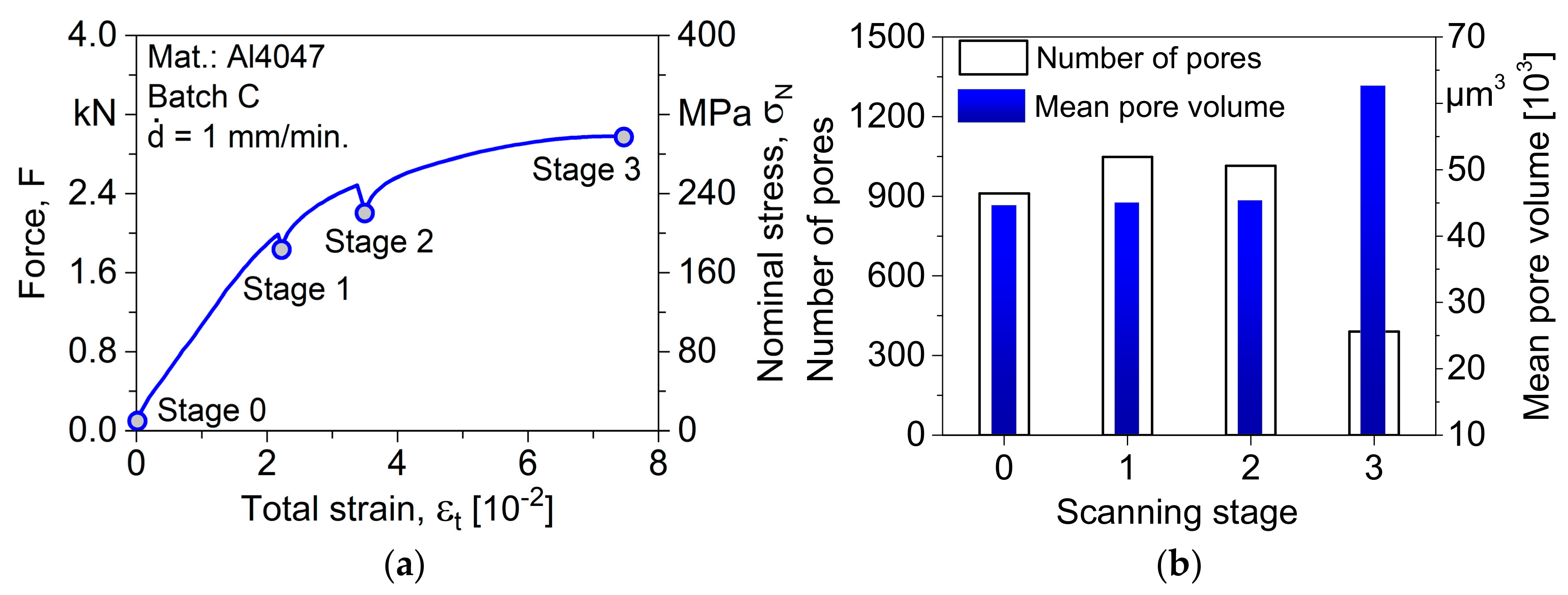
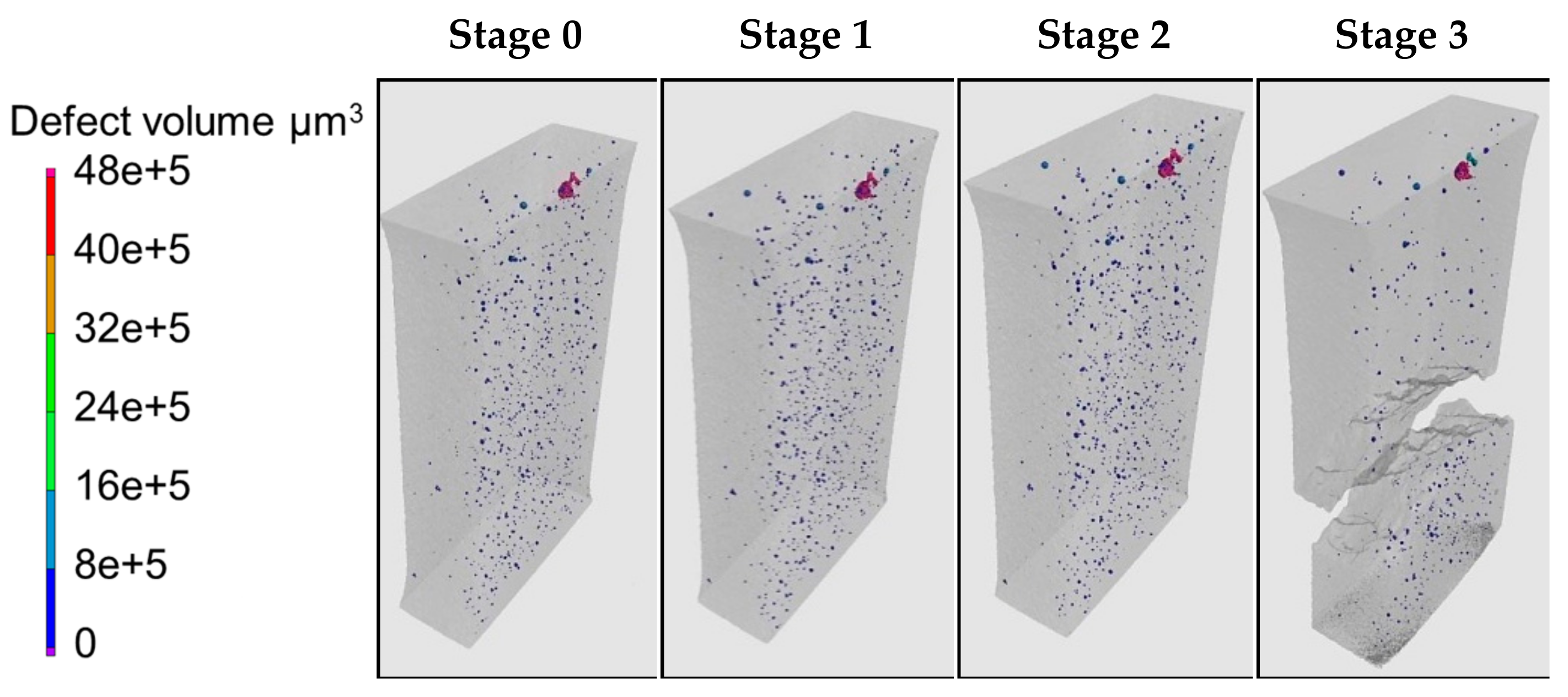
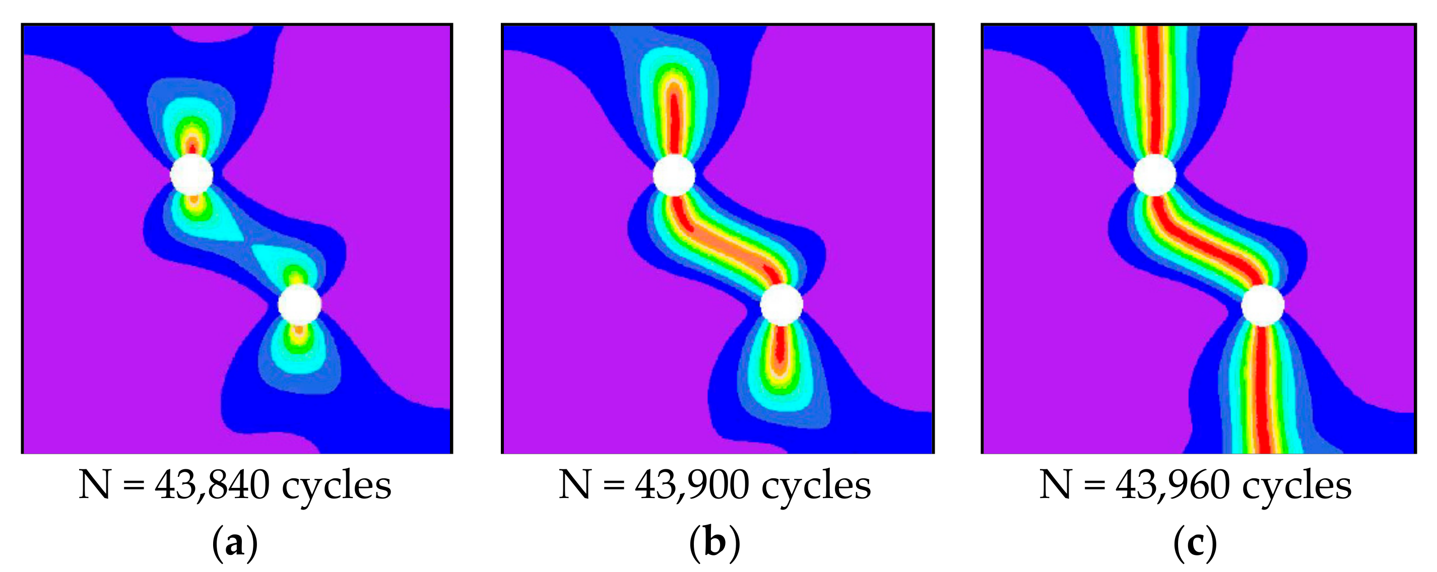
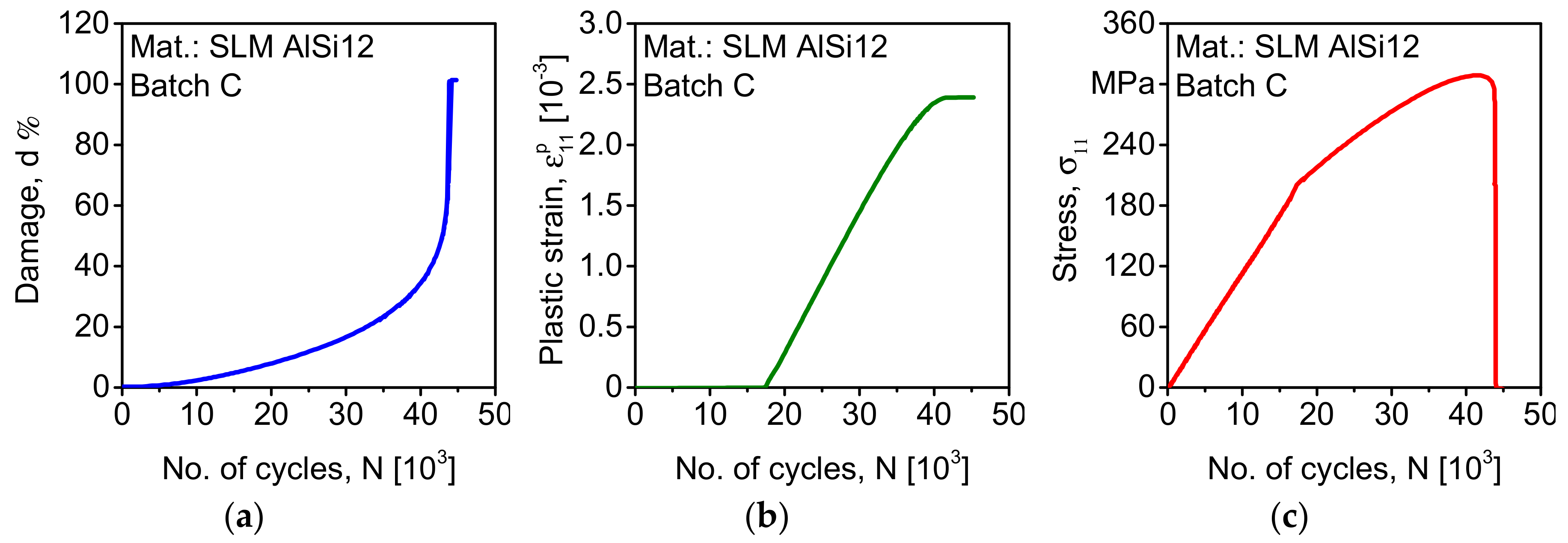
3.3. Damage Behavior in Interrupted Loading

Tensile tests were performed with interrupted loading inside an X-ray CT chamber where the test specimen was scanned during the interrupted loading stages to evaluate the damage behavior. For these tests, pure Al4047 batch C was selected due to its relatively more damage-tolerant behavior determined in quasistatic tests as well as residual stress states. Three tests were performed to have reliable results and to assign statistical values to the measured values. Stress-strain curve resulting from one of these tests is shown in Figure 6a.
The specimen was scanned at four stages: before the start of the test (stage 0), at two intermediate stages (stage 1 and stage 2), and finally after fracture (stage 3). The damage level in the gauge length of the specimen, as scanned by computed tomography is shown in Figure 7. The calculation of a number of defects and mean pore volume was calculated from the CT scans at the four stages and is represented in Figure 6b. Before starting tensile loading, the specimen had 911 pores and a mean pore volume of 44,599 µm3. The number of pores went up to 1048 at stage 1, with an accompanying mean pore volume of 45,013 µm3, which is a marginal increase in pore volume showing the start of new pore formation while their size is very small. The mean pore volume increased to 45,268 µm3 at stage 3 with the number of pores at that stage being 1015 showing a decrease in number due to the start of pore coalescence. After fracture at stage 3, there were only 390 pores while the mean pore volume reached to 62,638 µm3 due to the integration of pores.
The stress-strain behavior in Figure 6a gives information about stress relaxation during the intermediate stages. At stage 1 and stage 2, there is a decrease in stress when the load is removed from the specimen for scanning, where the value of this stress relaxation is more at stage 2 when compared to stage 1. This behavior can be attributed to the motion of dislocations in the material. Higher value of plastic deformation at stage 2 will be having a higher speed of dislocation movement, resulting in increased stress relaxation, which is also a reason of increased fracture strain in interrupted tests as compared to continuous tensile tests, as portrayed in Table 4, where fracture strain increased from 4.05 × 10⁻² to 4.36 × 10⁻² with an accompanying decrease in ultimate tensile strength. This type of mechanism was also reported recently for stainless steel in [46].

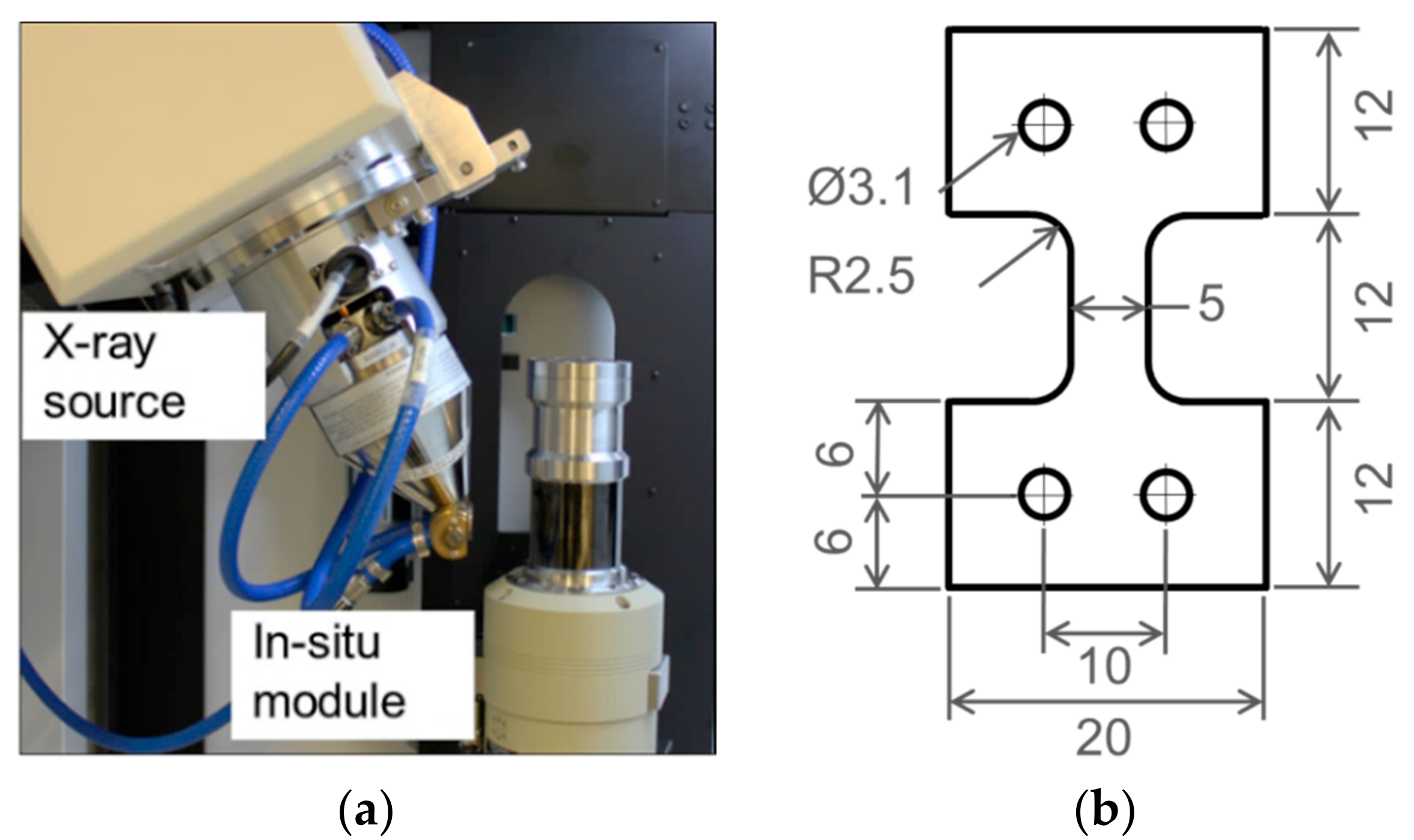
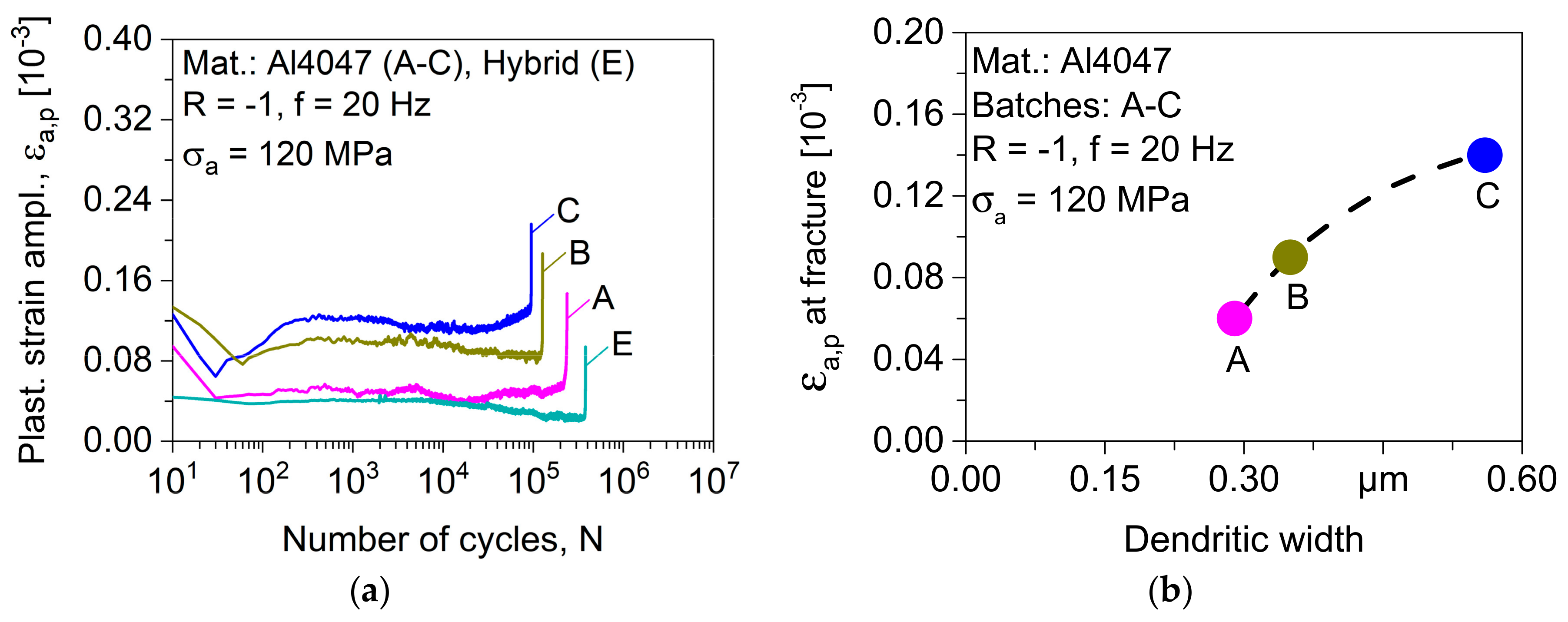
3.4. HCF and VHCF Behavior

The damage behavior that was investigated by load increase tests with the measurement of plastic strain amplitude (Figure 8a) is shown in Figure 8b. As-built hybrid specimens without post-build stress-relief were not tested under load increase tests due to the fracture mechanism activated at the joint interface. In the response of cyclic loading in terms of plastic strain amplitude, the sensitivity of the damage development under different conditions can be evaluated. Generally, all the batches show two different regions of response starting at the quasi-constant magnitude of plastic strain amplitude which increases slightly as the microcracks start initiating in the structure. After a critical value of stress amplitude, in this case around 110 MPa, the response parameter increases exponentially showing the growth of the initiated crack until failure. Therefore, the constant amplitude tests performed after this critical stress amplitude will allow for mechanism-based understanding of the fatigue phenomenon under different processing conditions.
Further constant amplitude tests were performed at a stress amplitude of 120 MPa for the same processing conditions, and Figure 9 elaborates their cyclic deformation behavior. From the pure Al4047 conditions, the as-built batch A endured the longest fatigue life conforming to the life obtained in load increase test in Figure 8b. After stress-relief in batch B, the fatigue life was reduced, and the reduction in fatigue life continued further for the batch C built with base plate heating. All of these three conditions of pure Al4047 (batch A–C) experience an initial rise in plastic strain amplitude followed by a drop up to around 60 load cycles. The following behavior can be explained by the process-related structure. Very small cyclic softening is experienced in the as-built condition (batch A), and the proceeding changes in the damage behavior are only minor until it increases in the second stage of cyclic softening towards the final stage of fatigue life. As the microstructural features in this condition are very thin, as shown by the dendritic width of 0.29 µm in Figure 9b, which offer high resistance to dislocation movement in the structure resulting in very small deformation, i.e., at plastic strain amplitude of 0.06 × 10⁻³ at fracture. After post-process stress-relief in batch B, having a dendritic width of 0.35 µm, the strain at fracture increased to 0.09 × 10⁻³, and an observable cyclic softening can be seen.
In the specimen processed with base plate heating (batch C), the plastic strain amplitude at fracture increased to 0.14 × 10⁻³ where a dendritic width of 0.56 µm allowed for plastic deformation in the material and the resulting fatigue life decreased. For the hybrid configuration (batch E), the plastic strain amplitude remains below in all phases of fatigue life as compared to the pure Al4047 configurations. The fusion of the two materials at the joint of conventionally manufactured and additively melt interface has resulted in decreased plastic strain amplitude and a correspondingly increased fatigue life. The relationship of the processing conditions with the corresponding dendritic width and the related softening and hardening mechanisms explain the fatigue life conditions, showing that the processing conditions can be controlled for the required microstructural features.
Complete Woehler curves were generated for the configurations with post-process stress-relief, i.e., batches B and C for the pure Al4047 and batch E for the hybrid condition. These tests were performed at 20 Hz on the servohydraulic system and at 20 kHz on the ultrasonic system, as elaborated in the legend in Figure 10. For the pure alloy condition Al4047 built by SLM process, the influence of base plate heating has been found critical under the influence of applied stress amplitude. At high-stress amplitude, finer microstructure (batch B) resulted in higher fatigue life as compared to relatively coarse microstructure (batch C) obtained when base plate heating is employed; however, as the applied stress amplitude is lowered, the trend is inversed where base plate heated specimens in batch C endured longer. Here the special feature of the SLM process, i.e., the role of remnant porosity comes into play. In general, HCF resistance is dominated by resistance to crack initiation where fine grain size offers more fatigue life; however, the difference in the remnant porosity of the two batches explains the inversed behavior at lower stress amplitudes. At a lower value of stress amplitude, the very small-sized defects remain inactive, and the mechanism of fatigue failure has more than one dimension as compared to higher stress amplitude where a single mechanism dominates the fatigue behavior. The ultrafine grains, even after base plate heating, has resulted in higher fatigue lives. But, when the existing pore size is relatively large, they become active and cause early failure, as in batch B. For the hybrid configuration of batch E, they have outperformed the pure alloy condition, as could also be seen in the result of load increase test that they offer less cyclic softening as compared to the pure alloy condition, due to better joining in the interface region of the two materials, which shifted the mechanism of fatigue failure out of the interface region. The fractures in hybrid specimens were from the SLM side.
Influence of test frequency on the resulting fatigue life is an important aspect for the utilization of the ultrasonic fatigue tests. The Woehler curves in Figure 10 show that the tests performed at 20 Hz and 20 kHz show similar trend lines. Investigation of the effect of frequency was performed by using the homogeneity of variance tests using a significance level of 0.05. Levene’s test with squared deviations as well as Brown-Forsythe test were conducted to calculate the statistical significance. Levene’s test with squared deviations resulted in a p-value of 0.116 (F:3.995) and the Brown-Forsythe test resulted in a p-value of 0.338 (F:1.179), which shows that the p-values lie far below the significance level of 0.05. Therefore it can be concluded that the underlying null hypothesis of different fatigue lives is not acceptable and it can be concluded with statistical significance that there is no difference in the fatigue lives resulting from the two test frequencies.
A square plate with two holes, shifted relative to each other, is chosen as a numerical example. It consists of AlSi12 with the parameters listed in Table 5. The plate dimensions are 100 × 100 μm and it is discretized by a mesh of approximately 7000 elements. The average element size is set to 1 μm; whereas, a finer discretization is performed in areas where the crack is expected to propagate. Simulations are carried out with a cyclic displacement driven test. The increment of the amplitude is chosen to be 0.0001 μm/cycle.
Displacements are applied on the right edge of the sample, whereas the displacements on the left edge are constrained. The different stages of crack propagation are presented in Figure 11. The cracks initiate at the surface of the holes at the applied displacements of 4.384 μm and thereafter propagate rapidly. The sample collapses at the prescribed displacements of 4.396 μm. The evolution of the damage parameter d, the ε 11 P component of the plastic strain tensor and the σ 11 component of the stress tensor are presented in Figure 12.
The values correspond to a node at the top of the right hole where one of the cracks initiates. The following conclusions can be drawn here. The rate of the stress decreases after the initiation of the plastic strain. The damage parameter rapidly increases once a certain value is exceeded. The kink of the stress/cycle curve goes back to the fact that hardening in the current model is not coupled with the damage.

4. Conclusions

The eutectic microstructure obtained in SLM-processed Al4047 can be controlled as per requirement using the appropriate SLM processing conditions where cooling rate plays the most important role. Ultra-fine grains are obtained which can be coarsened by pre-heating the base plate in SLM chamber. Pre-heating the base plate also resulted in reducing the remnant porosity from 0.38% to 0.29% where more time is available to the relatively stable melt pool, such that the gas bubbles could escape through the melt reducing the gas porosity.
Quasistatic properties obtained in SLM-processed Al4047 are higher as compared to their cast counterparts due to fine grains as well as the solubility of Si in the matrix where less free Si has reduced the brittleness, which is evident in the simultaneous change in tensile strength as well as fracture strain. Interrupted quasistatic testing inside computed tomography chamber has shown the phenomenon of stress relaxation in this alloy, which further increased the ductility. Hybrid specimens resulted in slightly reduced strength but significantly increased ductility which can be employed for manufacturing hybrid structures reducing the costs.
Fatigue strength of SLM structures has been found dependent not only on the microstructure but also on the remnant porosity. The interaction of the two mechanisms has changed the fatigue strength depending on the applied stresses where base plate heating has been found, resulting in less strength at high-stress amplitude, and higher strength than its non-base plate heated counterpart at lower stress amplitudes. Hybrid structures have resulted in higher fatigue strength as compared to pure Al4047 over the whole range of applied stress amplitude due to the low level of cyclic softening in hybrid specimens. Influence of test frequency has not been found to be significant for the investigated Al alloys. The phase-field method was applied as a tool to numerically calculate the onset of damage, crack initiation, and ultimate failure. An extension of the model in order to incorporate the kinematic hardening and influence of the damage on material constants will be part of the future work.

Author Contributions

S.S., M.A., and T.W. contributed to the methodology, investigation, and writing of the original draft. S.K. and F.W. supervised the investigations and reviewed and edited the manuscript.

Funding

This research was funded by the Deutsche Forschungsgemeinschaft (DFG, German Research Foundation) grant number: WA 1672/25-1.

Acknowledgments

The authors thank the DFG for its support within the research project “Mechanism-based understanding of functional grading focused on fatigue behavior of additively processed Ti-6Al-4V and Al-12Si alloys”.

Conflicts of Interest

The authors declare no conflict of interest.

References

  1. Kempen, K.; Thijs, L.; Humbeeck, J.; Kruth, J. Mechanical properties of AlSi10Mg produced by selective laser melting. Phys. Procedia 2012, 39, 439–446. [Google Scholar] [CrossRef]
  2. Siddique, S.; Wycisk, E.; Frieling, G.; Emmelmann, C.; Walther, F. Microstructural and mechanical properties of selective laser melted Al 4047. Appl. Mech. Mater. 2015, 752–753, 485–490. [Google Scholar] [CrossRef]
  3. Vilaro, T.; Colin, C.; Bartout, J.; Nazé, L.; Sennour, M. Microstructural and mechanical approaches of the selective laser melting process applied to a nickel-base superalloy. Mater. Sci. Eng. A 2012, 534, 446–451. [Google Scholar] [CrossRef]
  4. Li, R.; Liu, J.; Shi, Y.; Wang, L.; Jiang, W. Balling behavior of stainless steel and nickel powder during selective laser melting process. Int. J. Adv. Manuf. Technol. 2012, 59, 1025–1035. [Google Scholar] [CrossRef]
  5. Kabir, M.; Richter, H. Modeling of processing-induced pore morphology in an additively-manufactured Ti-6Al-4V alloy. Materials 2017, 10, 145. [Google Scholar] [CrossRef] [PubMed]
  6. Lee, Y.; Kirka, M.; Dinwiddie, R.; Raghavan, N.; Turner, J.; Dehoff, R.; Babu, S. Role of scan strategies on thermal gradient and solidification rate in electron beam powder bed fusion. Addit. Manuf. 2018, 22, 516–527. [Google Scholar] [CrossRef]
  7. Prashanth, K.; Scudino, S.; Klauss, H.; Surreddi, K.; Löber, L.; Wang, Z.; Chaubey, A.; Kühn, U.; Eckert, J. Microstructure and mechanical properties of Al–12Si produced by selective laser melting: Effect of heat treatment. Mater. Sci. Eng. A 2014, 590, 153–160. [Google Scholar] [CrossRef]
  8. Siddique, S.; Awd, M.; Tenkamp, J.; Walther, F. High and very high cycle fatigue failure mechanisms in selective laser melted aluminum alloys. J. Mater. Res. 2017, 32, 4296–4304. [Google Scholar] [CrossRef] [Green Version]
  9. Kruth, J.; Badrossamay, M.; Yasa, E.; Deckers, J. Part and material properties in selective laser melting of metals. In Proceedings of the 16th International Symposium on Electromachining, Shanghai, China, 19–23 April 2010. [Google Scholar]
  10. Siddique, S.; Imran, M.; Wycisk, E.; Emmelmann, C.; Walther, F. Influence of process-induced microstructure and imperfections on mechanical properties of AlSi12 processed by selective laser melting. J. Mater. Process. Technol. 2015, 221, 205–213. [Google Scholar] [CrossRef]
  11. Mercelis, P.; Kruth, J. Residual stresses in selective laser sintering and selective laser melting. Rapid Prototyp. J. 2006, 12, 254–265. [Google Scholar] [CrossRef]
  12. Liu, Z.; Jiang, Y.; Wang, G.; Yang, Y.; Zhang, L. Gradient in microstructure and mechanical property of selective laser melted AlSi10Mg. J. Alloys Compd. 2018, 735, 1414–1421. [Google Scholar] [CrossRef]
  13. Prashanth, K.; Eckert, J. Formation of metastable cellular microstructures in selective laser melted alloys. J. Alloys Compd. 2017, 707, 27–34. [Google Scholar] [CrossRef]
  14. Buchbinder, D.; Meiners, W.; Wissenbach, K.; Poprawe, R. Selective laser melting of aluminum die-cast alloy—Correlations between process parameters, solidification conditions, and resulting mechanical properties. J. Laser Appl. 2015, 27, S29205. [Google Scholar] [CrossRef]
  15. Wycisk, E.; Siddique, S.; Herzog, D.; Walther, F.; Emmelmann, C. Fatigue performance of laser additive manufactured Ti-6Al-4V in very high cycle fatigue regime up to 1E9 cycles. Front. Mater. 2015, 2, 72. [Google Scholar] [CrossRef]
  16. Edwards, P.; Ramulu, M. Fatigue performance evaluation of selective laser melted Ti-6Al-4V. Mater. Sci. Eng. A 2014, 598, 327–337. [Google Scholar] [CrossRef]
  17. Awd, M.; Tenkamp, J.; Hirtler, M.; Siddique, S.; Bambach, M.; Walther, F. Comparison of microstructure and mechanical properties of Scalmalloy® produced by selective laser melting and laser metal deposition. Materials 2018, 11, 17. [Google Scholar] [CrossRef] [PubMed]
  18. Siddique, S.; Awd, M.; Tenkamp, J.; Walther, F. Development of a stochastic approach for fatigue life prediction of AlSi12 alloy processed by selective laser melting. Eng. Fail. Anal. 2017, 79, 34–50. [Google Scholar] [CrossRef]
  19. Rafi, H.; Pal, D.; Patil, N.; Starr, T.; Stucker, B. Microstructure and mechanical behavior of 17-4 precipitation hardenable steel processed by selective laser melting. J. Mater. Eng. Perform. 2014, 23, 4421–4428. [Google Scholar] [CrossRef]
  20. Alrbaey, K.; Wimpenny, D.; Tosi, R.; Manning, W.; Moroz, A. On optimization of surface roughness of selective laser melted stainless steel parts: A statistical study. J. Mater. Eng. Perform. 2014, 23, 2139–2148. [Google Scholar] [CrossRef]
  21. Liu, Y.; Li, S.; Wang, G.; Hou, W.; Hao, Y.; Yang, R.; Sercombe, T. Microstructure, defects and mechanical behavior of beta-type titanium porous structures manufactured by electron beam melting and selective laser melting. Acta Mater. 2016, 113, 56–67. [Google Scholar] [CrossRef]
  22. Liu, Z.; Wang, H.; Li, S.; Wang, S.; Wang, W.; Hou, W.; Hao, Y.; Yang, R.; Zhang, L. Compressive and fatigue behavior of beta-type titanium porous structures fabricated by electron beam melting. Acta Mater. 2017, 126, 58–66. [Google Scholar] [CrossRef]
  23. Wycisk, E.; Emmelmann, C.; Siddique, S.; Walther, F. High cycle fatigue (HCF) performance of Ti-6Al-4V alloy processed by selective laser melting. Adv. Mater. Res. 2013, 816–817, 134–139. [Google Scholar] [CrossRef]
  24. Siddique, S.; Imran, M.; Rauer, M.; Kaloudis, M.; Wycisk, E.; Emmelmann, C.; Walther, F. Computed tomography for characterization of fatigue performance of selective laser melted parts. Mater. Des. 2015, 83, 661–669. [Google Scholar] [CrossRef]
  25. Brandl, E.; Heckenberger, U.; Holzinger, V.; Buchbinder, D. Additive manufactured AlSi10Mg samples using selective laser melting (SLM): Microstructure, high cycle fatigue, and fracture behavior. Mater. Des. 2012, 34, 159–169. [Google Scholar] [CrossRef]
  26. Leuders, S.; Thoene, M.; Riemer, A.; Niendorf, T.; Tröster, T.; Richard, H.; Maier, H. On the mechanical behavior of titanium alloy Ti-6Al-4V manufactured by selective laser melting: Fatigue resistance and crack growth performance. Int. J. Fatigue 2013, 48, 300–307. [Google Scholar] [CrossRef]
  27. Mughrabi, H. Specific features and mechanisms of fatigue in the ultrahigh-cycle regime. Int. J. Fatigue 2006, 28, 1501–1508. [Google Scholar] [CrossRef]
  28. Spriestersbach, D.; Grad, P.; Kerscher, E. Crack initiation mechanisms and threshold values of very high cycle fatigue failure of high strength steels. Procedia Eng. 2014, 74, 84–91. [Google Scholar] [CrossRef]
  29. Qian, G.; Hong, Y.; Zhou, C. Investigation of high cycle and very high cycle fatigue behaviors for a structural steel with smooth and notched specimens. Eng. Fail. Anal. 2010, 17, 1517–1525. [Google Scholar] [CrossRef]
  30. Pyttel, B.; Schwerdt, D.; Berger, C. Very high cycle fatigue—Is there a fatigue limit? Int. J. Fatigue 2011, 33, 49–58. [Google Scholar] [CrossRef]
  31. Guennec, B.; Ueno, A.; Sakai, T.; Takanashi, M.; Itabashi, Y. Effect of loading frequency in fatigue properties and micro-plasticity behavior of JIS S15C low carbon steel. In Proceedings of the 13th International Conference on Fracture, Beijing, China, 16–21 June 2013. [Google Scholar]
  32. Tsutsumi, N.; Murakami, Y.; Doquet, V. Effect of test frequency on fatigue strength of low carbon steel. Fatigue Fract. Eng. Mater. Struct. 2009, 32, 473–483. [Google Scholar] [CrossRef]
  33. Furuya, Y.; Torizuka, S.; Takeuchi, E.; Bacher-Hoechst, M.; Kuntz, M. Ultrasonic fatigue testing on notched and smooth specimens of ultrafine-grained steel. Mater. Des. 2012, 37, 515–520. [Google Scholar] [CrossRef]
  34. Stanzl-Tschegg, S.; Mayer, H.; Schuller, R.; Przeorski, T.; Krug, P. Fatigue properties of spray formed hypereutectic aluminium silicon alloy DISPAL® S232 at high and very high numbers of cycles. Mater. Sci. Eng. A 2012, 538, 327–334. [Google Scholar] [CrossRef]
  35. Zhu, X.; Jones, J.; Allison, J. Effect of frequency, environment, and temperature on fatigue behavior of E319 cast aluminum alloy: Stress-controlled fatigue life response. Metall. Mater. Trans. A 2008, 39, 2681–2688. [Google Scholar] [CrossRef]
  36. Miehe, C.; Welschinger, F.; Hofacker, M. Thermodynamically consistent phase-field models of fracture: Variational principles and multi-field FE implementations. Int. J. Numer. Methods Eng. 2010, 83, 1273–1311. [Google Scholar] [CrossRef]
  37. Francfort, G.; Marigo, J. Revisiting brittle fracture as an energy minimization problem. J. Mech. Phys. Solids 1998, 46, 1319–1342. [Google Scholar] [CrossRef]
  38. Bourdin, B.; Francfort, G.; Marigo, J. The variational approach to fracture. J. Elast. 2008, 91, 5–148. [Google Scholar] [CrossRef] [Green Version]
  39. Nagaraja, S.; Elhaddad, M.; Ambati, M.; Kollmannsberger, S.; De Lorenzis, L.; Rank, E. Phase-field modeling of brittle fracture with multi-level hp-FEM and the finite cell method. arXiv, 2018; arXiv:1804.08380. [Google Scholar]
  40. Kiendl, J.; Ambati, M.; De Lorenzis, L.; Gomez, H.; Reali, A. Phase-field description of brittle fracture in plates and shells. Comput. Methods Appl. Mech. Eng. 2016, 312, 374–394. [Google Scholar] [CrossRef] [Green Version]
  41. Alessi, R.; Vidoli, S.; De Lorenzis, L. A phenomenological approach to fatigue with a variational phase-field model: The one-dimensional case. Eng. Fract. Mech. 2018, 190, 53–73. [Google Scholar] [CrossRef]
  42. Siddique, S.; Imran, M.; Walther, F. Very high cycle fatigue and fatigue crack propagation behavior of selective laser melted AlSi12 alloy. Int. J. Fatigue 2017, 94, 246–254. [Google Scholar] [CrossRef]
  43. Simchi, A. Direct laser sintering of metal powders: Mechanism, kinetics and microstructural features. Mater. Sci. Eng. A 2006, 428, 148–158. [Google Scholar] [CrossRef]
  44. Monroy, K.; Delgado, J.; Ciurana, J. Study of the pore formation on CoCrMo alloys by selective laser melting manufacturing process. Procedia Eng. 2013, 63, 361–369. [Google Scholar] [CrossRef]
  45. DIN. Aluminium and Aluminium Alloys—Castings—Chemical Composition and Mechanical Properties; EN 1706; DIN: Berlin, Germany, 2013. [Google Scholar]
  46. Li, X.; Li, J.; Ding, W.; Zhao, S.; Chen, J. Stress relaxation in tensile deformation of 304 stainless steel. J. Mater. Eng. Perform. 2017, 26, 630–635. [Google Scholar] [CrossRef]
Figure 1. Characteristics of Al4047 powder: (a) morphology of powder particles; and, (b) the corresponding powder size distribution (PSD).
Applsci 08 01948 g001
Figure 2. Experimental strategy for manufacturing of test specimens: (a) chessboard scanning strategy; (b) orientation of each layer at 79°; (c) exemplary lot of the as-built specimens from the selective laser melting (SLM) process; (d) test specimen for tensile and high cycle fatigue tests; and, (e) test specimen for very high cycle fatigue tests, dimensions in mm.
Applsci 08 01948 g002
Figure 3. (a) Setup for in-situ tensile tests in the X-ray CT chamber; and, (b) the miniature specimen used for these tests, dimensions in mm.
Applsci 08 01948 g003
Figure 4. Part parameters of SLM-processed Al4047: (a) part morphology; (b) microstructural features for batch B; (c) microstructural features for batch C; and, (d) residual stresses as a function of the dendritic width.
Applsci 08 01948 g004aApplsci 08 01948 g004b
Figure 5. Characteristic stress-strain curves for Al4047 specimens: as-built batch A; stress-relieved batch B; base plate heated and stress-relieved batch C; the as-built hybrid batch D; and, stress-relieved hybrid batch E.
Applsci 08 01948 g005
Figure 6. (a) Representative tensile behavior in interrupted tests for batch C performed inside computed tomography chamber; and, (b) development of damage behavior in terms of number of pores and mean pore volume at the interrupted stages.
Applsci 08 01948 g006
Figure 7. Damage state in no-load condition (stage 0), at two stages during the tensile test (stage 1, stage 2), and after fracture (stage 3) represented by interrupted CT scans.
Applsci 08 01948 g007
Figure 8. (a) Schematic representation of used load increase test with accompanied measurement of plastic strain amplitude (εa,p); and, (b) the resulting damage behavior of the investigated batches.
Applsci 08 01948 g008
Figure 9. (a) Cyclic deformation behavior of the investigated batches at 120 MPa stress amplitude; and, (b) cyclic fracture strain (εa,p) as a function of dendritic width.
Applsci 08 01948 g009
Figure 10. Woehler curve until very high cycle fatigue range for pure Al4047 by SLM process (with stress-relief batch B, and with base plate heating and stress-relief batch C), and for hybrid batch Al7020+Al4047 with stress-relief batch E.
Applsci 08 01948 g010
Figure 11. Crack propagation in the sample with two circular pores. The results show the crack propagation for the prescribed displacements: (a) 4.384 μm; (b) 4.390 μm; and, (c) 4.396 μm.
Applsci 08 01948 g011
Figure 12. Evolution of: (a)the damage parameter d; (b) the first component of the plastic strain tensor ε 11 p ; and, (c) the first component of the stress tensor σ 11 .
Applsci 08 01948 g012
Table 1. Experimental plan for investigation of Al4047 and hybrid (Al7020+Al4047) specimens.
BatchMaterialBase Plate Heating (BPH)Stress-Relief (SR)
AAl4047--
BAl4047-240 °C
CAl4047200 °C240 °C
DHybrid--
EHybrid-240 °C
Table 2. The nominal chemical composition of Al4047 powder.
ElementAlSiCuFeMnZnTiOthers
wt%Bal.12.000.050.550.350.100.150.05
Table 3. Percentage remnant porosity in batches A, B, and C.
BatchABC
Remnant porosity [%]0.260.380.29
Table 4. Comparison of tensile properties in interrupted and continuous tests.
Test ModeσUTS [MPa]εt,max [10−2]
Interrupted324.10 ± 23.106.36 ± 1.29
Continuous361.10 ± 4.504.05 ± 0.15
Table 5. Material parameters used in the simulation for AlSi12.
Young’s ModulusPoisson’s RatioYield LimitIsotropic Hardening
E [GPa]υ k y 0 [MPa]H [GPa]
700.3218123.45

