Detection of Thermal Strain in Steel Rails with BOTDA
by
 ,
,
Lijuan Gu
1,5 ,
,
Liang Zhang
1,
Xiaoyi Bao
1,*,
Merrina Zhang
2,
Chengxian Zhang
3 and
Yongkang Dong
4 1
Department of of Physics, University of Ottawa, Ottawa, ON K1N 6N5, Canada
2
National Research Council Canada, Ottawa, ON K1V 1S2, Canada
3
NFX Systems Inc., Ottawa, ON K1N 6N5, Canada
4
Department of Electronic Science of Technology, Harbin Institute of Technology, Harbin 150001, China
5
School of Physics, Peking University, Beijing 100871, China
*
Author to whom correspondence should be addressed.
Appl. Sci. 2018, 8(11), 2013; https://doi.org/10.3390/app8112013
Submission received: 29 August 2018
/
Revised: 18 October 2018
/
Accepted: 20 October 2018
/
Published: 23 October 2018
(This article belongs to the Special Issue Optical Correlation-domain Distributed Fiber Sensors)
Abstract
:Rail transportation is one of the most important and efficient forms of transportation. Large thermal strain can develop in the rail steel due to extreme climatic conditions resulting in safety related issues. We carried out a thermal-strain monitoring test on the rail specimen over a large temperature range from −40 C to +50 C using a Brillouin optical time-domain analyzer (BOTDA) for the first time, to the best of our knowledge. Two jacketed fibers and small-diameter carbon/polyimide-coating single-mode fiber were used for the purpose of investigating the jacket effect of thermal-strain detection on the rail. Although a nonlinear response to the temperature of the loose jacketed fiber was found, it was applicable for thermal strain monitoring when glued on the surface of the rail sample. The measured thermal strain in the rail specimen was validated by the results obtained by the strain gauge. The thermally induced strain from the large rail specimen was found to have suppressed the nonlinear impact of the fiber jacket.
1. Introduction
Rail transportation is one of the most important and efficient forms of transportation. Railway networks are fixed structures that can span many thousands of kilometers. Rail infrastructure typically consist of rail steel anchored onto wooden ties, which sits on a layer of crushed rock ballast over soil foundations. Rail steel is produced in fixed lengths of between 12–120 m. For passenger rail transportation, the preferred method of track construction is to weld sections of rail steel together as a continuously welded rail (CWR). However, CWR does not allow for the expansion or contraction of the rail steel with changes in ambient temperature. This results in thermally induced stresses in the rail (compressive when hot, tensile when cold), which can be extremely large and contribute to rail breaks in cold weather, or rail buckling in hot weather. The long term strain and measurement of rail steel is challenging due to the vastness of most track infrastructure and the harsh climatic operating environment. A high spatial resolution-distributed optical fiber sensor based on Brillouin scattering is a very promising technique for this application.
A Brillouin scattering-based optical fiber sensor takes advantage of the optical fiber as the sensing medium to measure both the temperature and strain along the length of the fiber. It has been successfully in many Structural Health Monitoring (SHM) [1,2] applications. However, distributed Brillouin sensors are commonly used to monitor the strain induced by different loading to the structure [3]. Thermal strain of the steel structure caused by temperature changes is rarely investigated. Bao et al. carried out an outdoor test to measure the strain of the steel beam under external loading force, and used a compensation technique to compensate for the temperature change caused by sun radiation [4]. However, in their test, the temperature change value from sunrise and during the night was limited. For the measurement of rail thermal strain, the optical fiber should be properly chosen to protect the fiber from damage (i.e., with a jacket coating) and to maintain detection sensitivity [5]. In practical applications, the tight-buffered fiber is widely used in distributed fiberoptic sensors. It is important to note that, the coating material influences the measured Brillouin frequency shift variation with temperature [6,7]. Gu et al. [7] performed a theoretical and experimental investigation of the effect of the polymer coating on the Brillouin frequency shift with temperature, however, the work concentrated on the temperature range above zero centigrade.
This paper reports the continuous thermal-strain monitoring of the rail steels using a Brillouin optical time-domain analyzer (BOTDA) for the temperature range between −40 C and +50 C. Three types of optical fiber were glued on the surface of the rail specimen as the distributed sensor; the free fiber between was used as the reference and could be used to investigate the jacket effect as well. Optical fibers are looped five times at different positions on the rail to investigate the position dependence of the thermal strain on the rail. The measurement is also compared to the reference that is obtained by the strain gauge implemented on the middle of the steel rail. This is the first time that optical fiber was used to monitor rail thermal strain in such a broad temperature range, to the best of our knowledge. We found the loose fiber with tight buffer material has a nonlinear relationship with the Brillouin frequency shift and the temperature change due to the temperature-dependent mechanical property of the coating and buffer material. However, when glued onto the rail to detect thermal strain, the measured Brillouin frequency shifts of all fibers exhibited a linear relationship with the temperature change, albeit with lightly different slope coefficients. This was attributed to the dominant thermal strain of the rail track that turned out to suppress the fiber jacket-induced nonlinear response of the Brillouin frequency shift, validating their applicability in distributed optical fiber strain sensing.
2. Laboratory Test
2.1. Test Setup
The sensor system used in this test is based on differential pulse-width pair (DPP) BOTDA that was reported previously [8]. A conventional BOTDA system takes advantage of the loop configuration in which the counter-propagating probe pulse and CW pump are used to activate the stimulated Brillouin scattering along the optical fiber [9]. Using a shorter-width probe pulse can improve spatial resolution; however, Brillouin frequency-shift accuracy can be compromised, resulting from a broadened Brillouin gain spectrum (BGS) and weaker Brillouin gain. In a DPP-BOTDA system, the trade off between spatial resolution and Brillouin frequency-shift accuracy is prohibited since it employs pulse pairs with slightly different pulse width, and subtracts their corresponding BGS to simultaneously achieve a narrow BGS and fine spatial resolution. With a high spatial resolution of 20 cm, the BOTDA system has the ability to monitor the thermal strain caused by temperature variation in rail specimens with a length of 50 cm. It should be noted that the data collected at a specific point on the rail specimen correspond to the average value within the length of the spatial resolution, i.e., 20 cm. Accordingly, the measured Brillouin frequency captured from both edges of the specimen with a distance of less than 20 cm include some portion of the loose fiber between two glued fiber sections. Thus, only the data point in the middle of the rail along the longitudinal direction adequately represents the rail strain. The measurement accuracy is 1 C or, equivalently, 20 . The scanning frequency range was set to be 10.4–11 GHz, with a scanning frequency interval of 6 MHz.
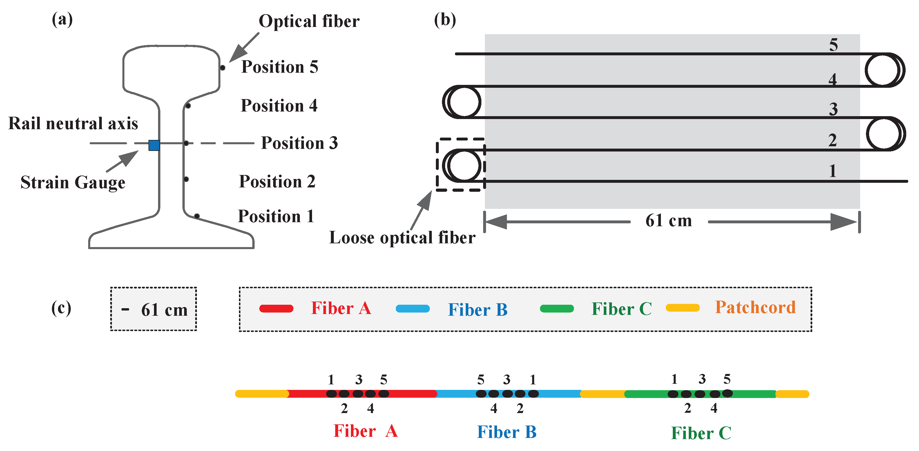
The rail specimens under the test were 115lbs RE rail formerly used in freight rail service in Canada. Each sample was approximately 61 cm in length. Each specimen was instrumented with three types of optical fiber and strain gauge at different sides of the rail specimen, as shown in Figure 1. According to the front and side view of the specimen in Figure 2a–c, five sensing fiber sections were mounted on the surface of the rail specimen at different positions, with 50 cm of loose fiber separating one sensing section from another. To evaluate the jacket effect on thermal-strain measurement, three types of fibers were tested, including two types of 900 m tightly buffered fiber from two different companies, and the carbon/polyimide coating fiber (BF04447, OFS, Norcross, GA, USA) with a diameter of 155 m. Each fiber was looped five times, and different types of fiber were fusion-spliced directly end-to-end or through an optical fiber patchcord. The overall connection diagram of the sensing fibers can be seen in Figure 2c, with plotting scale and fibers represented by Fiber A, B, and C in the following for simplicity. Detailed information on all the fibers can be found in Table 1. The sensing fibers were fixed with steel adhesive (Loctite 4861, Henkel, Düsseldorf, Germany) under pretension. The steel adhesive was firstly placed along the top line of the fiber, and then the adhesive gravity pulled itself into the gap between the fiber and the rail steel. In this manner, small bubbles that may have influenced the strain transfer into the fiber were prohibited and extra strain caused by gluing process was minimized.
All the rail specimens instrumented with sensing fibers were placed inside a climate chamber that could be programmed to achieve the required temperature condition. To better mimic climate conditions of real applications, the temperature range of the experiment was set to be from C to +C with a variation step of C. It took 1 h for the chamber to increase from one temperature step to the next, and each temperature step was held for 4 h for repeated measurement.
2.2. Measurement Principle
Distributed optical fiber sensing based on Brillouin scattering takes advantage of light interaction with the acoustic phonons propagating in the fiber core [9]. The frequency shift of Brillouin-scattered light is proportional to the acoustic phonons velocity, and can be given by:
where is the effective refractive index of the optical fiber, is the free-space wavelength of the pump light, and acoustic wave velocity depends on the local density and tension of the glass that contribute to the temperature and strain dependence of the Brillouin frequency shift.
The temperature response of the loose jacketed fiber results from two effects, including the Brillouin frequency shift with the temperature of the bare fiber and the thermal strain generated by the difference between thermal-expansion coefficients in bare fiber and its jacket material [6]. The temperature variation-induced frequency shift of can then be written as the following [10]:
Here, is the Brillouin frequency shift with the temperature of the bare single-mode fiber (including fiber coating) that is calibrated to be at a constant value, with a value of 1.01 MHz/C [7], strain coefficient was measured to be 0.048 MHz/ [11], and represents the axial strain along the fiber caused by the thermal-expansion mismatch of the fiber and the jacket material. The jacket effects are commonly modeled by Lamé solutions [12], in which the jacketed fiber is considered to have a multilayer structure as indicated in Figure 3. In our case, a two-layer model, including the bare single-mode fiber and an external jacket layer, was utilized. Following the Lamé formulas for the strain components in a cylindrical fiber subjected to a differential temperature, and assuming no external force to the jacketed fiber, the induced axial thermal force can be given by [13]:
where is the Young’s modulus of the jacket material, is the effective thermal expansion coefficient of the jacket material at the given temperature, is the instantaneous thermal-expansion coefficient, is the zero-strain temperature of the jacket material, and . Then, we can get the axial strain variation with temperature and, hence, the Brillouin frequency variation with temperature on the single-mode fiber:
Here, is the Young’s modulus of the bare fiber. We can see that the Brillouin frequency shift of the jacketed fiber is determined by the Young’s modulus, thermal-expansion coefficient, and the radius of each layer.
Considering the fiber glued on the rail specimen, there is external force generated by the thermal expansion or contraction of the rail specimen to the optical fiber. Strain by the rails, the effects of the jacket material, and the optical fiber itself may contribute to the measured Brillouin frequency shift under different temperatures. As a result, each single contribution has to be determined by considering the Young’s modulus of the materials, and the dimension of both the rail and the jacketed fiber for thermal-force measurement.
3. Results and Discussion
3.1. Thermal Effect of Fiber Jacket
First, the Brillouin frequency shift of the loose optical fiber under different temperatures is shown in Figure 4. According to the figure, Fiber C had a linear response for the entire temperature range in the test, and the measured Brillouin frequency shift with the temperature was calculated to be 1.04 MHz/C, which was slightly larger than that of the standard single-mode fiber without any coating (1.01 MHz/C ) [7]. This slightly larger shift of the Brillouin frequency with temperature was caused by the extra stain transfer from the coating layer to the cladding due to the elastic-modulus difference between the carbon/polyimide coating and the inside silica cladding. Linear Brillouin frequency change within such a large temperature range demonstrates the stable thermomechanical property of the coating material.
However, the Brillouin frequency shift of Fibers A and B had a nonlinear response with temperature variation in a broad temperature range. Quadratic curve fitting was used, and perfect matching with the measured data was obtained. Based on the fitting function, the ratio of Brillouin frequency shift with temperature variation can be given as:
where indicate the results for Fiber A and Fiber B, separately, and and is the coefficient of the quadratic term and linear term in the fitting equation displayed on Figure 5. As was previously mentioned, the temperature coefficient of the bare fiber was constant, and, after extraction, this constant from Equation (2), the thermal strain caused by the optical jacket material, was temperature-dependent. This, we believe, is a consequence of a mechanical-property change of the fiber jacket material with temperature, i.e., the Young’s modulus and thermal-expansion coefficient of the jacket material being temperature-dependent. Both of the tight buffer fibers have larger thermal strain when the temperature is lower than 0 C, since has a negative value. The reason behind that is the Young’s modulus of jacket material, which is the polyvinyl chloride, increases with decreasing temperature in a low temperature region; hence, the thermal strain between bare fiber and the coating material increases. Instead of taking advantage of this excess strain, when used in distributed sensing, this nonlinear response of a tight buffer fiber should be calibrated.
3.2. Vertical Distribution of Thermal Strain on the Rail Specimen
As indicated from Figure 2, the lateral profile of the rail sample is not regular and, in order to precisely verify the climate adaptability of the rail using the Brillouin frequency shift of the fiber glued on it, thermal-strain distribution should be taken into consideration. During the lab test, five loops of optical fiber were fixed in different positions of the rail to quantify this effect. The Brillouin frequency variation with the temperature of Fiber B in different vertical positions on the rail can be found in Figure 5a, where Positions 1–5 represent different positions from the bottom to the top. The Brillouin coefficient is defined as the ratio of the Brillouin frequency shift with temperature for simplicity. The Brillouin coefficients at different positions are also shown in Figure 5b, with the error bar and the dashed line representing the average value of all the Brillouin coefficients. According to the figure, the deviations from the average value of all values in different positions are within measurement accuracy, which indicates the position independence of the thermal strain.
3.3. Thermal-Strain Measurement on the Rail Specimen
Next, the Brillouin frequency shift with temperature variation of the three types of fiber glued on the rail specimen can be found in Figure 6. Since we found that the results from the fiber glued at different parts of the rail were similar, we only chose the results collected from the neutral axis for comparison. The thermal effect of the jacketed fiber that comprised the bare optical fiber and jacket material, strain glue, and thermal strain of the rail may have contributed to the measured results. All of the three fibers had a perfectly linear response, which makes it rather interesting because two types of loose jacketed fiber have a nonlinear Brillouin frequency response, especially in a low temperature range (lower than 0 C). Since the optical fibers were glued on the rail and, when the rail underwent extension in high temperatures and extraction in low temperatures, the fiber on the rail would elongate or shrink in the meanwhile. The results clearly show that the thermal strain caused by the rail expansion and contraction played a dominant role on the Brillouin frequency shift of the fiber due to its large thermal strain on the jacketed fiber, and the thermal-strain nonlinearity by the fiber jacket could be neglected. As a result, all the fibers that were glued on the rail had a linear Brillouin frequency shift with a temperature change that verified the applicability of all the fibers for thermal-strain monitoring of the rail specimen.
Through linear fitting, the Brillouin frequency-shift variations with the temperature of all three types of fiber are summarized in Table 2. Subtracting the Brillouin frequency shift of the bare fiber, the corresponding strain was calculated by taking advantage of the strain coefficient of the normalized Brillouin frequency shift of the single-mode fiber, which was 0.048 MHz/ [11]. The difference between the results from the strain gauge with BOTDA from three types of fiber was within measurement accuracy. Nevertheless, different types of fibers have a slightly different response to the same strain from the rail, providing an important instruction to practical applications, that is, before applying a certain kind of fiber to monitor rail thermal strain, calibration should first be done; BOTDA is one promising approach.
3.4. Measurement Accuracy
In this test, measurement accuracy is indicated using measurement repeatability. It took about 9 min for every measurement with the BOTDA system, and more than 20 data points could be collected during every temperature step. Standard deviation of the measured Brillouin frequency shift at each data point was considered, and the error bars in Figure 5 and Figure 6 were calculated based on the standard deviation from 10 Brillouin frequency-shift measurements made at each fiber position along the rail specimen. According to Table 2, the standard deviation of the strain captured by three types of fibers was 0.83 , 1.25 , and 0.42 , respectively. Compared with the OFS fiber (Fiber C), such higher measurement uncertainty of the two tight buffer fibers was caused by the jacket effect.
4. Conclusions
This laboratory test has verified the feasibility of using BOTDA in thermal-strain rail monitoring under a broad temperature range. Although the fiber jacket may cause a nonlinear temperature response of the Brillouin frequency shift, with its linear correspondence when glued on the rail, the jacketed fiber is suitable for thermal-strain sensing of the rail. Along the vertical position of the rail specimen, position independence of the thermal strain was found. Moreover, owing to a slightly different Brillouin frequency shift induced by the same amount of strain using different types of fiber, a calibration process is suggested to first be carried out in field applications.
Author Contributions
L.G. is the lead author of the article, in addition to performing the experiments using the BOTDA and the data analysis, and wrote the article; L.Z., and C.Z. helped to prepare the experiment; M.Z. wrote portions of the article, as well as designed and performed the climatic testing; Y.D. provided the technical support for the BOTDA unit and fiber A; and X.B. supported the design of the experiment, reviewed data analysis, and the writing of the paper.
Funding
This research was funded by NRC of Bao/National Research Council Canada 150406, by NSERC of NSERC Discovery grant RGPIN-2015-06071 and by CRC of CRC chair fund 950-231352.
Acknowledgments
The authors acknowledge funding support from the National Research Council Canada, NSERC, and the Canada Research Chair Program for the support.
Conflicts of Interest
The authors declare no conflict of interest.
Abbreviations
The following abbreviations are used in this manuscript:
| BOTDA | Brillouin Optical Time Domain Analyzer |
| CWR | Continuously Welded Rail |
| SHM | Structural Health Monitoring |
| DPP | Differential Pulse-Width Pair |
| BGS | Brillouin Gain Spectrum |
References
- DeMerchant, M.D.; Brown, A.; Bao, X.; Bremner, T.W. Structural monitoring by use of a Brillouin distributed sensor. Appl. Opt. 1999, 38, 2755–2759. [Google Scholar] [CrossRef] [PubMed]
- Ravet, F.; Zou, L.; Bao, X.; Ozbakkaloglu, T.; Saatcioglu, M.; Zhou, J. Distributed Brillouin sensor for structual health monitoring. Can. J. Civ. Eng. 2007, 34, 291–297. [Google Scholar] [CrossRef]
- Zhang, C.; Bao, X.; Ozkan, I.F.; Mohareb, M.; Ravet, F.; Du, M.; DiGiovanni, D. Prediction of the pipe buckling by using broadening factor with distributed Brillouin fiber sensors. Opit. Fiber Technol. 2007, 14, 109–113. [Google Scholar] [CrossRef]
- Bao, X.; DeMerchant, A.; Brown, A.; Bremner, T. Tensile and Compressive Strain Measurement in the Lab and Field with the Distributed Brillouin Scattering Sensor. J. Lightwave Technol. 2001, 19, 1698–1704. [Google Scholar]
- Ding, Y.; Shi, B.; Bao, X.; Gao, J. Jacket effect on strain measurement accuracy for distributed strain sensors based on Brillouin scattering. Opt. Appl. 2006, 36, 57–67. [Google Scholar]
- Kurashima, T.; Horiguchi, T.; Tateda, M. Thermal effects on the Brillouin frequency shift in jacketed optical silica fibers. Appl. Opt. 1990, 29, 2219–2222. [Google Scholar] [CrossRef] [PubMed]
- Gu, H.; Dong, H.; Zhang, G.; He, J.; Pan, H. Effects of Polymer Coatings on Temperature Sensitivity of Brillouin Frequency Shift Within Double-Coated Fibers. IEEE Sens. J. 2013, 13, 864–869. [Google Scholar] [CrossRef]
- Dong, Y.; Bao, X.; Li, W. Differential Brillouin gain for improving the temperature accuracy and spatial resolution in a long-distance distributed fiber sensor. Appl. Opt. 2009, 48, 4297–4301. [Google Scholar] [CrossRef] [PubMed]
- Bao, X.; Chen, L. Recent Progress in Brillouin Scattering Based Fiber Sensors. Sensors 2011, 11, 4152–4187. [Google Scholar] [CrossRef] [PubMed] [Green Version]
- Smitt, J.; Brown, A.; DeMerchant, M.; Bao, X. Simultaneous distributed strain and temperature measurement. Appl. Opt. 1999, 38, 5372–5377. [Google Scholar] [CrossRef]
- Parker, T.R.; Frhadiroushan, M.; Handerek, V.A.; Rogers, A.J. Rature and strain dependence of the power level and frequency of spontaneous Brillouin scattering in optical fibers. Opt. Lett. 1997, 22, 787–789. [Google Scholar] [CrossRef] [PubMed]
- Lagakos, N.; Bucaro, J.A.; Jarzynski, J. Temperature-induced optical phase shifts in fibers. Appl. Opt. 1981, 20, 2305–2308. [Google Scholar] [CrossRef] [PubMed]
- Suhir, E. Mechanical Approach to the Evaluation of the Low. Temperature Threshold of Added Transmission Losses in Single-Coated Optical Fibers. J. Lightwave Technol. 1990, 8, 863–868. [Google Scholar] [CrossRef]
Figure 1.
Rail specimen instrumented with strain gauge and optical fibers on each side.

Figure 2.
(a) Cross section of the rail specimen; (b) layout of a certain type of fiber (Fiber A, Fiber B, or Fiber C) glued on the surface of the rail specimen with a length of 61 cm; (c) overall connection diagram of three types of sensing fiber along the rail specimen.
Figure 2.
(a) Cross section of the rail specimen; (b) layout of a certain type of fiber (Fiber A, Fiber B, or Fiber C) glued on the surface of the rail specimen with a length of 61 cm; (c) overall connection diagram of three types of sensing fiber along the rail specimen.

Figure 3.
Demonstration of the two-layer structure of the optical fiber with a cladding diameter of m and a jacket diameter of .
Figure 3.
Demonstration of the two-layer structure of the optical fiber with a cladding diameter of m and a jacket diameter of .

Figure 4.
Brillouin frequency-shift variation with the temperature of three loose optical fibers.

Figure 5.
(a) Brillouin frequency variation with the temperature of Fiber B at different positions of the rail specimen; (b) Brillouin coefficient at different positions in the vertical direction of the rail.
Figure 5.
(a) Brillouin frequency variation with the temperature of Fiber B at different positions of the rail specimen; (b) Brillouin coefficient at different positions in the vertical direction of the rail.

Figure 6.
Brillouin frequency-shift variation with the temperature of different fibers glued on the same rail.
Figure 6.
Brillouin frequency-shift variation with the temperature of different fibers glued on the same rail.


Table 1.
Diameters of the jacketed fiber.
| Fiber | Fiber A | Fiber B | Fiber C |
|---|---|---|---|
| Jacket diameter (m) | 850 ± 50 | 900 | 155 ± 5 |
| Jacket material | Polyvinyl chloride | Flame-retardant polyvinyl chloride | Carbon/PYROCOAT |
Table 2.
Brillouin frequency-shift variation with the temperature of different fibers on the rail.
| Rail | Fiber A | Fiber B | Fiber C | Strain Gauge |
|---|---|---|---|---|
| (MHz/C) | 1.53 ± 0.04 | 1.47 ± 0.06 | 1.51 ± 0.02 | |
| Strain() | 10.83 ± 0.83 | 9.58 ± 1.25 | 10.42 ± 0.42 | 10.7 |
© 2018 by the authors. Licensee MDPI, Basel, Switzerland. This article is an open access article distributed under the terms and conditions of the Creative Commons Attribution (CC BY) license (http://creativecommons.org/licenses/by/4.0/).
Share and Cite
MDPI and ACS Style
Gu, L.; Zhang, L.; Bao, X.; Zhang, M.; Zhang, C.; Dong, Y. Detection of Thermal Strain in Steel Rails with BOTDA. Appl. Sci. 2018, 8, 2013. https://doi.org/10.3390/app8112013
AMA Style
Gu L, Zhang L, Bao X, Zhang M, Zhang C, Dong Y. Detection of Thermal Strain in Steel Rails with BOTDA. Applied Sciences. 2018; 8(11):2013. https://doi.org/10.3390/app8112013
Chicago/Turabian StyleGu, Lijuan, Liang Zhang, Xiaoyi Bao, Merrina Zhang, Chengxian Zhang, and Yongkang Dong. 2018. "Detection of Thermal Strain in Steel Rails with BOTDA" Applied Sciences 8, no. 11: 2013. https://doi.org/10.3390/app8112013
Note that from the first issue of 2016, this journal uses article numbers instead of page numbers. See further details here.