Thermal Management Systems for Civil Aircraft Engines: Review, Challenges and Exploring the Future


Centre for Propulsion Engineering, School of Aerospace Transport and Manufacturing (SATM), Cranfield University, Cranfield MK43 0AL, UK
*
Author to whom correspondence should be addressed.
Appl. Sci. 2018, 8(11), 2044; https://doi.org/10.3390/app8112044
Submission received: 26 September 2018
/
Revised: 15 October 2018
/
Accepted: 22 October 2018
/
Published: 24 October 2018
(This article belongs to the Special Issue Gas Turbine Engine - towards the Future of Power)
Abstract
:This paper examines and analytically reviews the thermal management systems proposed over the past six decades for gas turbine civil aero engines. The objective is to establish the evident system shortcomings and to identify the remaining research questions that need to be addressed to enable this important technology to be adopted by next generation of aero engines with complicated designs. Future gas turbine aero engines will be more efficient, compact and will have more electric parts. As a result, more heat will be generated by the different electrical components and avionics. Consequently, alternative methods should be used to dissipate this extra heat as the current thermal management systems are already working on their limits. For this purpose, different structures and ideas in this field are stated in terms of considering engines architecture, the improved engine efficiency, the reduced emission level and the improved fuel economy. This is followed by a historical coverage of the proposed concepts dating back to 1958. Possible thermal management systems development concepts are then classified into four distinct classes: classic, centralized, revolutionary and cost-effective; and critically reviewed from challenges and implementation considerations points of view. Based on this analysis, the potential solutions for dealing with future challenges are proposed including combination of centralized and revolutionary developments and combination of classic and cost-effective developments. The effectiveness of the proposed solutions is also discussed with a complexity-impact correlation analysis.
1. Introduction
New designs of gas turbine civil aero-engines are increasingly complex. Nowadays, we are facing with More Electric Aircraft (MEA) with higher demands on engines for thrust and power generation resulting in hotter fluids, higher components temperature and higher heat generation, which means critical thermal management issues. So, it is time to think differently about how we can manage the thermal loads in modern gas turbine engines. In other words, future aircraft propulsion systems should be able to meet ambitious targets and severe limitations set by governments and organizations (e.g., the Advisory Council for Aviation Research and Innovation in Europe has a target of a 75% reduction in CO2 emissions and a 90% reduction of NOx emissions by 2050) [1]. These targets cannot be achieved just through marginal improvements in turbine technology or aircraft design.
High power and high heat flux cooling requirements of new aero-engine designs result in generation of more excess heat by Gas Turbine Engines (GTEs). The Thermal Management System (TMS) plays a key role in dealing with this heat to limit payload size and to enhance the engine performance. The TMS utilizes engine fluids to transfer excess heat from the engine heat sinks like bearings, accessory gearbox, pumps, generators, constant speed drive and power gearbox in new geared turbofans. It is worthwhile to mention that the TMS structure is not usually discussing the turbine blade cooling and the cooling mechanisms used for this purpose as it has a separate circuit fed by the compressor bleed air. A comprehensive review about the cooling mechanisms for high level heat flux components [2,3,4], physic-based models and cooling mechanisms (convection, film, transpiration cooling, cooling effusion, pin fin cooling etc.) [5,6,7,8] and control systems for the associated cooling mechanisms could be found widely in the literature [9,10,11].
Of course, there are limitations and constraints in TMS design and implementation. For instance, the total volume and weight of the TMS will be limited by engine design and geometry. Moreover, the operable temperature for fuel, oil and other fluids communicated throughout the engine should be maintained. Engine oil may undergo coking and fuel may undergo lacquering, gumming, or varnishing above certain temperature limits [12]. These constraints limit the heat sink capacity of the TMS and highlight the requirement of a smart optimized TMS design for modern GTEs. In addition, an optimized TMS should be able to increase engine performance by using the engine excess heat (e.g., heat may be transferred into the engine fuel in order to increase the fuel efficiency).
In the last 60 years, many ideas, concepts, embodiments and research studies have been done on thermal management systems for gas turbine aero-engines to meet all thermal load management requirements and to achieve optimized performance for the TMS and the engine. The historical progress in the development of TMS for aerospace applications can for convenience be divided into three phases:
- Phase 1: Pioneering work: The first two decades (between 1958 and 1978). The first theoretical studies and embodiments’ presentation were undertaken, resulting in generation of the main ideas for the aerospace TMS: using two heat exchangers for the engine thermal management, using catalyst to increase the fuel heat capacity and oil flowrate tuning through the heat exchangers to control the engine fuel temperature. These ideas helped researchers to build a very strong integration phase in the field.
- Phase 2: Integration: The second two decades (between 1978 and 1998). The idea of having integrated thermal management system for engine and airframe is presented and discussed in several embodiments in this phase. Moreover, the most practical idea for the TMS structure, having two separate cooling loops for the management of engine heat loads, is also proposed and developed.
- Phase 3: Detailed Design: The last two decades (between 1998 and 2018). More comprehensive studies based on detailed testing and real applications were published in this phase. The ideas of new advanced structures for the TMS, fuel temperature control in TMS and using different cooling fluids like water, Therminol, which is a synthetic heat transfer fluid and thermally neutral heat transfer fluid (TNHTF) are presented and discussed as well.
Obviously, the above-mentioned phases are concentrated on different ranges of power and technology development that was the state of the art in the date of research. Table 1 shows the quantitative analysis of different phases that would be discussed in next chapters.
Moreover, taking the new advances in material sciences into account, it could be seen that the turbine entry temperature has had an average increase of about 8 °C rise per year over the last 20 years [17]. It is due to the new advanced materials used for the turbine manufacturing in new aircraft engines (e.g., SC cast alloys and ceramics). So, more increase in thermal loads is expected for the future engines. Consequently, designing an optimal thermal management system architecture is a key factor for the heat management in future civil engines.
The most important publications and milestones during phases 1 to 3 are discussed in detail in next sections. Section 2, focuses on pioneering work and concepts dating back to 1958. Section 3 describes the integration phase in thermal management system architecture design that occurred between 1978 and 1998. Section 4 concentrates on detailed design phase in the last two decades addressing the state of the art technologies for thermal load managements in civil aero engines. Based on the results of these sections, different classes of development for the future thermal management systems design are classified and described in detail and the pros and cons of each class is discussed in Section 5. Based on this discussion, two potential solutions for dealing with future challenges of thermal management systems are proposed and illustrated. The conclusion remarks are also presented in Section 6.
2. Pioneering Work on Thermal Management Systems Design
First, in 1958 an invention presented on oil cooling and drag reducing system for high speed vehicles such as aircraft, sleds, or boats. It is the first publicly available publication that presents thermal management system architecture for aircraft engine systematically [18]. Moreover, another invention related to lubricating oil cooling systems for turbojet engines presented in 1963 [19]. The main idea of these two patents were to utilize two heat exchangers, Air/Oil Heat Exchanger (AOHE) and Fuel/Oil Heat Exchanger (FOHE), to dissipate extra heat generated by engine components. These two heat exchangers could be mounted in the cooling loop in series or parallel architecture.
In 1969, a patent was registered by Nodding et al. in which a cooling system for engine and airframe is proposed where fuel is used as the heat sink to absorb frictional heat produced by airstream passing over wing and fuselage surface [20]. They showed that by using a catalyst an endothermic chemical reaction would be promoted, allowing fuel to absorb more heat. The main idea is to break down the fuel into smaller molecules and to alter the fuel’s characteristics as a propellant. However, this embodiment requires temperature of 700 to 1000 °F for operation and is consequently limited in high supersonic or hypersonic applications.
Finally, fuel delivery control system and its effects in oil cooling system of gas turbine aero engines was discussed at last years of the pioneering work phase [21,22]. The main idea of these embodiments was to use a position control valve to tune the oil flowrate in FOHE in order to protect the engine from fuel over temperature and malfunctions.
Consequently, the main presented ideas of the pioneering work phase could be summarized as follow:
- (1)
- Using two heat exchangers to manage the excess heat of the engine: FOHE and AOHE
- (2)
- Using a catalyst to increase the fuel heat absorption capacity
- (3)
- Tuning the oil flow rate through the FOHE to control the engine fuel temperature
These interesting ideas were the main motivations for the next phase.
3. Integration Phase on Thermal Management Systems Design
From 1978, the integration phase in TMS design and development started. The idea of having integrated TMS for the engine and airframe was proposed for the first time by Frosch, et al. in 1981 [23]. The main idea was to refrigerate fuel to deal with all cooling requirements that resulted in necessitating additional power for the refrigeration system. However, as the cooling demand of the airframe and engine increase, the required quantity of heat absorbing fuel is increased as well. So, the cooling capability will be reduced significantly near the end of mission because of the minimal quantity of the fuel. Also, the other prior art based on fuel refrigeration was proposed in 1985 that had the same disadvantage as discussed above [24,25].
As a milestone, United Technologies Corporation registered a patent in 1987 on fuel and oil heat management system for a gas turbine engine [26]. This patent presented two different embodiments both contained two oil cooling loops, two fuel-oil heat exchangers and two air-oil heat exchangers to deal with cooling requirements of gas turbine engines. The heat exchangers characteristics and design is used from previous embodiments presented in References [27,28,29]. The embodiments are designed to manage the excess heat from different sources efficiently. The schematic of the architecture is shown in Figure 1. This structure has been used widely in real-world applications for thermal management of gas turbine aero-engines. The main working strategy of this embodiment could be described as follow:
- (1)
- The main heat sources of the engine like bearings and accessory gearbox will be cooled (and also lubricated) by main oil loop in which the oil will be distributed and collected throughout the main engine structure and then it will be returned to a collection point after absorbing excess heat generated by the engine components.
- (2)
- Another oil loop is designed to lubricate and to dissipate extra heat from accessory drive like constant speed drive for the aircraft service electrical generator.
This method is simple, straightforward and easy to design, implement and control. However, since the maximum temperature of the fuel is limited, an extra air flow from bleed valve is required to cool the oil loop in some situations and it results in increasing the overall engine power demand for a given level of useful thrust. This power penalty increases the engine thrust specific fuel consumption.
In 1988, Hudson and Levin proposed an integrated aircraft fuel thermal management system to optimize the TMS by integrating airframe and engine fuel heat sink systems into a composite heat sink and a secondary power source [30]. They used several accessories like boost pumps, bypass relief valves, temperature control valves and filters to control the fuel temperature and to reduce the dependency on supplemental ram air for the fuel cooling heat exchanger. Moreover, the engine control unit (ECU) is designed to be cooled by the airframe environmental control system (ECS) to increase its reliability. However, in this embodiment, the integrated drive generator (IDG), accessory drive gearbox (ADG) and airframe hydraulic system (Hyd) have not been considered by thermal management system with this assumption that they do not have critical temperature requirements.
The rest of the studies in the integration phase were focused on the above milestones and tried to sort out the disadvantages of the proposed ideas [31,32,33,34]. These efforts resulted in emerging another phase in TMS development for gas turbine aero-engines: the detailed design phase.
The main presented ideas of the integration phase could be summarized as follow:
- (1)
- Integrated cooling system for the engine and airframe
- (2)
- Designing two separate cooling paths for the engine thermal management
- (3)
- Integrating airframe and engine fuel heat sink systems into a composite heat sink and a secondary power source
4. Detailed Design Phase on Thermal Management Systems
After integration phase, the research studies and proposed ideas have been focused on the detailed design and novel ideas during the last two decades. Some of the most important achievements of this phase are covered in this section:
An interesting idea is to use the Cooled Cooling Air (CCA) system to improve the gas turbine engine efficiency. In 1999, air force research laboratory suggested that when utilizing the available heat sinks in a gas turbine engine, the overall engine performance could be improved [35]. The main novelty was to use a heat exchanger to cool the compressor bleed air to decrease the required air flow rate for the turbine blade cooling. Four different embodiments were investigated in detail and the results of the study showed that the CCA system with a fuel-to-air heat exchanger offers the greatest potential for improved engine performance while rescuing some of the dependence on advanced materials. The schematic of this idea is shown in Figure 2. However, the main drawback of this idea is its complexity and weight as well as safety and reliability considerations.
In 2002, Haung et al. focused on the fuel-cooled thermal management for advanced aero engine by utilizing endothermic cracking and reforming of hydrocarbon fuels [36,37]. By developing a bench-scale test rig, they presented a conceptual design to demonstrate the technologies necessary for utilizing conventional multi-component hydro-carbon fuels for fuel-cooled thermal management system including the development of the endothermic potential of JP-7 and JP-8+100, a demonstration of the combustion of supercritical/endothermic fuel mixture and conceptual design of a fuel-air heat exchanger [38,39]. However, the requirement of high fuel temperature (700 to 1200 °F) is still the limit of this concept [40,41].
Between 2004 and 2007, two comprehensive research studies were published on the remaining challenges for future aircraft power systems thermal management [42,43]. The main conclusion of these studies could be summarized as follow:
- (1)
- The first step in designing an optimized TMS for an aircraft engine is to precisely define the boundary conditions and to recognize the requirements and constraints of the specific system.
- (2)
- Different approaches should be taken for different applications and aircraft platform in order to optimize the power and TMS.
- (3)
- Different levels of heat flux should be discussed in detail and suitable approaches for each level should be proposed.
- (4)
- Since all power system components such as batteries, capacitors, power semiconductors, generators, pulsed power sources and beam conditioners have thermal design issues, partial solutions have been sought by way of increased heat transfer through the use of spray cooling, micro channels and subcooled boiling, loop heat pipes, capillary pumped loops, energy storage and spray cooling arrays.
In 2009, Maser et al. presented a thermal management modelling approach for integrated power system. Based on the control-volume method they developed a dynamic model for the TMS and the propulsion system in Numerical Propulsion System Simulation (NPSS) software and linked it to an electrical model created in MATLAB/Simulink [44]. However, in their model they assumed that the engine oil cooling would be dealt with using a separate cooling system. Moreover, the effect of the air bleed cooling system was not considered in this study.
In 2012, United Technologies Corporation presented another schematic of a two integrated loops TMS for gas turbine engines [45]. The main idea of this patent is to have two cooling loops with different temperature to deal with different levels of heat flux in flight mission. So, a thermal management system with an air-to-oil heat exchanger to provide the first conditioned fluid and a second (fuel-to-oil) heat exchanger to provide a second conditioned fluid and a third air-to-oil heat exchanger in parallel flow communication with the second heat exchanger to meet the fluid temperature limits was proposed as shown in Figure 3. In this figure, the first heat exchanger (Number 1) provides a first conditioned fluid (Number 2), a second heat exchanger (Number 3) exchanges heat with the first conditioned fluid (Number 2) to provide a second conditioned fluid (Number 4) and a third heat exchanger (Number 5) selectively exchanges heat with the first conditioned fluid (Number 2) to provide a third conditioned fluid (Number 6).
Therefore, the TMS in this embodiment enables the designer to have two cooling loops with different temperatures for engine thermal loads management.
A turbomachine structural assembly in which the nose cone provides an aperture that communicates air to an interior of the nose cone was proposed by Suciu et al. in 2013 [46]. This embodiment enhances the thermal management performance of the turbomachinery. However, more accessories like a motor and a clutch and a control mechanism is required for implementation of this idea. Some other embodiments are also focused on this topic and its pros and cons from practical point of view [47,48,49]. These patents focused on cooling requirements of GTE as well as engine fluids temperature limitations and based on defined boundary conditions, different structures and architectures for GTEs thermal management system were proposed in detail. The four different proposed architectures could be categorized as follow [50,51]:
- (1)
- The first system includes an air/oil heat exchanger and an oil/fuel heat exchanger as shown in Figure 4. A small percentage of the fan bypass duct air flow passes through the Air-to-Oil heat exchanger (AOH). This embodiment not only adds weight to the aircraft but also creates a pressure loss in the fan bypass duct airflow (BPA), resulting in a reduction in propulsive thrust.
- (2)
- The second idea is shown in Figure 5 includes an oil/fuel heat exchanger (OFH) that transfers heat from the hot engine oil. However, the oil returns directly to the engine from the OFH in this embodiment. In addition, this system includes an air/ fuel heat exchanger (AFH), which transfers heat from the fuel to a fraction of the aircraft inlet or nacelle airflow (NCA). It maintains the fuel at a sufficiently low temperature to adequately cool the engine oil under different engine operating conditions. This can be achieved because the design of the system is not compromised by constrains imposed on the systems shown in Figure 4. However, the system may still not be capable of handling all engine and aircraft operating conditions without exceeding either the fuel or engine oil operating temperatures limits, resulting in operational limits on the aircraft.
Figure 6 shows another TMS architecture which is particularly adapted for gas turbine engines with separate gearing structures (“gearboxes”). It includes an air/oil heat exchanger (AOH) in a gearbox lubricating oil line (GOL). In a fashion like that employed with the engine lubricating oil, the gearbox oil re-circulates from a sump, through the AOH and then back to the gear box. A separate heat transfer line (EOL) for the engine lubricating oil passes through an oil/fuel heat exchanger (OFH), so that heat from the engine lubricating oil is transferred to the fuel, in a fashion similar to that described in connection with the OFH in Figure 4 and Figure 5.
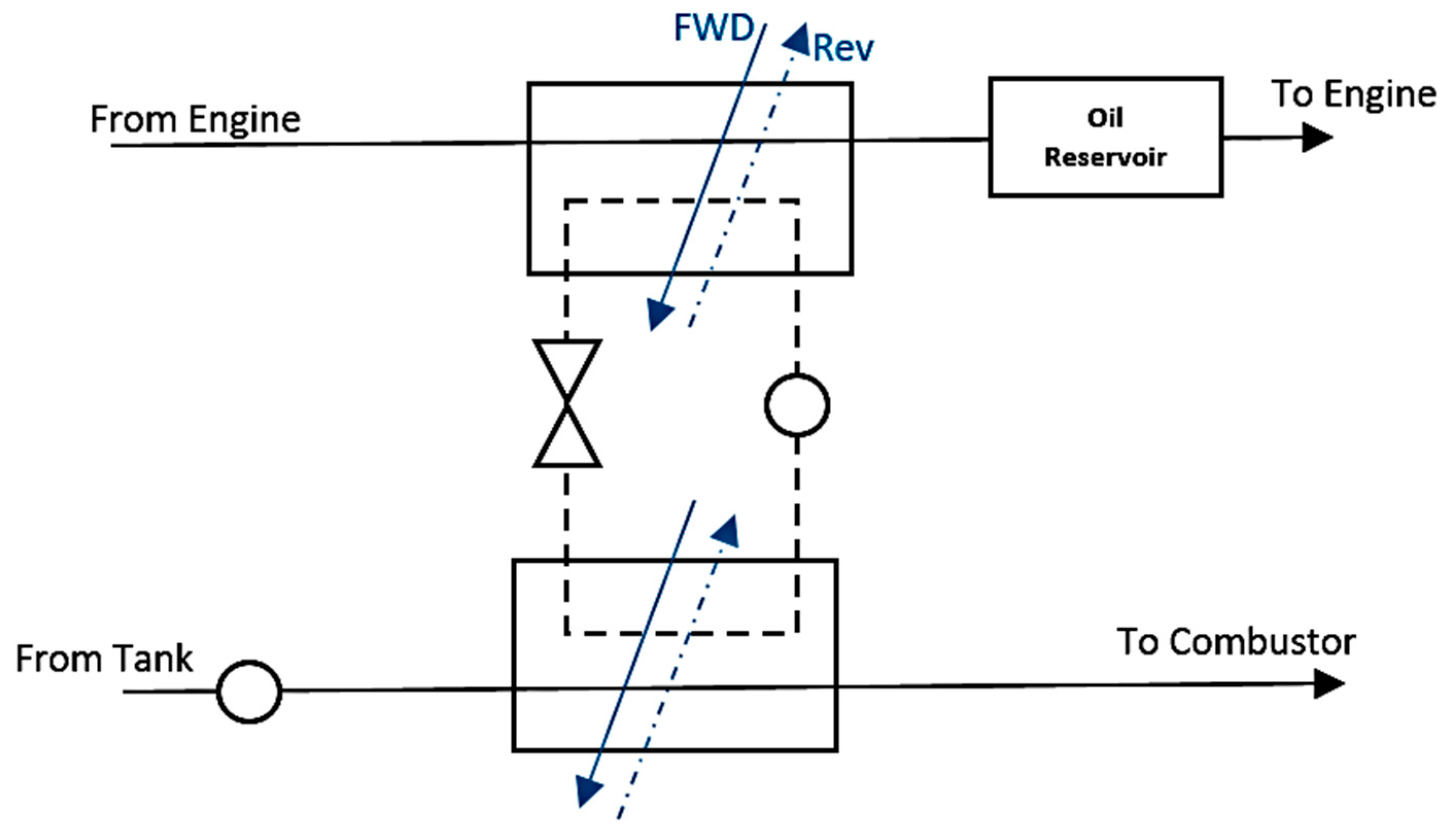
Another idea is to use a working fluid (e.g., water, Therminol, thermally neutral heat transfer fluid (TNHTF)) to absorb heat from engine fluids (oil and fuel). Two schematics of this idea are shown in Figure 7. A reversible heat pump is used in this embodiment to circulate a working fluid through heat exchangers. By employing this pump, the performance of the TMS system will improve operational flexibility that enables the heat transfer characteristics of the system to be more precisely controlled and more readily tailored to a particular engine across a greater range of operating conditions. The system will work in forward direction in normal operating conditions. As soon as one of engine fluids (oil or fuel or both) exceeds the temperature limit, the system will switch to reverse direction to protect the engine fluids from over-temperature and other physical limitations (e.g., cocking, lacquering, varnishing, etc.). However, the design and implementation of this system has its own complexity and considerations that should be taken into account.
In 2014, the von Karman institute for fluid dynamics in Belgium published an experimental study on thermal analysis of surface heat exchanger operating in transonic regime in which an integrated bypass-flow surface heat exchanger is modelled and tested to cope with the high cooling demands from innovative engine architectures. Their results showed that the investigated concept may provide up to 76% of the estimated lubrication cooling requirements during take-off of in a modern gas turbine power plant [51].
The idea of using thermally neutral heat transfer fluid (TNHTF) like Therminol and DOWTHERM for gas turbine engines TMS is becoming more widely focused in recent years. In 2016, United technologies Corporation presented an embodiment containing a fuel/TNHTF heat exchanger, an oil/TNHTF heat exchanger and an air/TNHTF heat exchanger to manage the excess thermal loads of GTEs [52]. The main advantage of this idea (shown in Figure 8) is the high potential of TNHTFs as heat sink in comparison with engine fluids (oil and fuel). However, the system should be designed precisely and the accurate flowrate control should be considered in order to satisfy the stability criteria of the system. In Figure 8, the proposed configuration of Fuel/TNHTF heat exchanger (1), oil/TNHTF heat exchanger (2) and air/TNHTF heat exchanger (3) are shown schematically.
Another idea, is to cool the compressor bleed air using a TNHTF in order to decrease the required volume of airflow for cooling the high-pressure turbine and increase the engine efficiency [53]. The schematic of this idea is shown in Figure 9. An accurate control system and a variable speed drive design should be considered in this idea.
Moreover, the fuel lacquering and other deposit formation is an important concern in thermal management system design. To deal with this problem, the idea of controlling fuel temperature based on the aircraft altitude is presented in 2016 by Teicholz and Stearns [54]. The control strategy was proposed to manage fuel temperature by using the altitude sensor data. For instance, the controller may schedule a decreased temperature for the conditioned fuel at lower altitudes (respect to high fuel oxygen content at low altitudes) and an elevated temperature for conditioned fuel at higher altitudes (e.g., during cruise and high-altitude climb).
In 2016, a comprehensive work on transient exergy analysis for thermal management of subsystem components was demonstrated and discussed [55]. Using experimental results, this study formulated a methodology for system level optimization to develop a dynamic air cycle machine (ACM) model at the Air Force Research Laboratory’s Modelling, Simulation, Analysis and Testing (MSAT) lab. The main outcome of this study was a “total efficiency parameter” defined by combining the exergy analysis. This parameter would help future simulation studies to be implemented on various system architectures to generate accurate models and predictive analysis.
In 2017, Rolls-Royce proposed different embodiments for high bypass geared turbofan engines TMS. This patent, proposed a heat exchange system for a power gearbox in an aircraft engine in which at least one heat transfer device is enclosed, embedded and/or attached with the casing of the power gearbox, wherein at least one airflow is directed to the one heat transfer device for thermally controlling the power gearbox. Different heat transfer devices can also be used in this idea for cooling/heating the power gearbox in different operating conditions [56,57].
Finally, in 2018, Rolls Royce has presented a novel idea on a closed dynamic cooling circuit for engine thermal management system. In this embodiment, a Thermal Energy Storage (TES) system is designed with two cooling circuit to manage the dynamic thermal load of the engine. So, each circuit has its own compressor and heat exchanger to be controlled to fully absorb thermal energy received by the TES [58]. The idea is very promising as both steady state and transient situations are being considered. However, the implementation considerations and stability issue should be considered with more details before the embodiment could go for the practical application.
The main ideas and milestones presented in the detailed design phase could be summarized as follow:
- (1)
- CCA thermal management system to increase the performance of the gas turbine engine by cooling the bypass air
- (2)
- Fuel cooled system with two different thermal management loops with different temperature levels to deal with all flight points efficiently
- (3)
- Using different coolants (e.g., water, Therminol and thermally neutral heat transfer fluid (TNHTF)) to manage the thermal loads in different points of the gas turbine engine.
5. TMS Design Challenges and Potential Solutions for the Next Generation of Aircraft Engines
From the historical review presented plus some general consideration of efficiency, energy management and coolant properties, it is possible to identify four different systematic concepts for the future of the TMS design and development as follows:
- Class I. Classic Development. This class of development would concentrate on the improvement of conventional TMS structure (Figure 1) for GTEs. This improvement could be applied on minor system structure changes in order to get better efficiency, replacement of the components with more advanced and smart ones (e.g., new, effective heat exchangers [59,60]) and changing the oil and fuel path to get better thermal management efficiency. The advantages of this approach are that the theoretical fundamentals and the implementation infrastructures are well-developed and these modifications would not dictate huge cost to manufacturers. However, the main disadvantage of this approach is that probably it would just bring marginal improvement for the TMS as this area is already well investigated.
- Class II. Centralized Development. This class would investigate the integrated TMS for the engine and airframe. It results in a centralized system that manages the thermal loads of the airframe and the engine simultaneously. So, the control algorithm and strategy would have more degree of freedom to deal with thermal loads. However, the main disadvantage is that it would be a high dimension multidisciplinary design problem with many parameters to select and tune simultaneously. Especially, in new advanced aircraft and engines it could be hardly affordable.
- Class III. Revolutionary Development. This class of development would cover new ideas with major changes in the TMS. Using new coolants for the engine ([50] and Figure 7) and ACC system ([35] and Figure 2) are examples of this class. The positive points about this class of development is that it may be possible to get a noticeable jump in TMS effectiveness. In other words, a revolutionary approach may result in a revolutionary achievement. But, the problem with this class of development is that implementation of these approaches requires a significant change in the system manufacturing and infrastructures and it may not be interesting for the airliners and manufacturers.
- Class IV. Cost-effective Development. This type of approaches will focus on the cost-effective solutions to enhance the TMS behaviour in the GTEs. The driving idea is to keep the hardware structure of the TMS unchanged (if possible) and to work on the solutions that could be implemented easily and/or with minimum changes in the current working systems. Enhancement of the control algorithms [61], splitters, valves and mixers [62] are some examples of cost-effective solutions. The relative merits of this class to the other classes is clear as the cost consideration is one of the most important issues in real-world applications. However, the correlation between the complexity and impact is the matter that should be discussed in these methods.
With respect to the above systematic approaches, the main drawbacks of the TMS development classes for the future aircraft engines are summarized in Table 2.
Considering that the above-listed drawbacks in some classes could be sorted out with using ideas of other classes, the potential solutions for the improvement of the aircraft engine TMS for the future could be proposed as follow:
- (1)
- The first effective solution could be utilizing both class I and IV simultaneously. It means that concentration of new studies should be on some minor modification on the hardware as well as working on algorithms and strategies. The superposition of these classes of development would enable the TMS designers to deal with several challenges in parallel. In one hand, the main architecture of the TMS would be kept approximately unchanged as the manufacturers and airliners prefer. On the other hand, minor changes in the components and cooling paths will give a huge degree of freedom to the control structure designers to play with more parameters in order to enhance the performance indices of the TMS and the engine noticeably. As an illustrative example, change the circulation path of the oil in parallel with defining a smart control algorithm for the variable valve positions may result in a noticeable enhancement in the TMS performance.
- (2)
- Another solution could be defining the classes II and III as a unique approach in an engineering optimization problem format. The main idea would be to define the structure of the integrated TMS, the order of components, the oil and fuel paths, the air flowrate and path and so forth, as the indices of a comprehensive objective function; then to use a powerful optimizer to deal with the defined objective function. By tuning the mutation operator probability, the potential evolutionary developments would be investigated as well. However, definition of very smart constraints, penalty functions, penalty factors and objective function indices coefficients is a very vital step in successfulness of this approach. So, the main step in this solution is to define the problem statement very clear and with high level of details and accuracy; and then to select a suitable optimizer which can deal with such a big optimization problem with affordable run time.
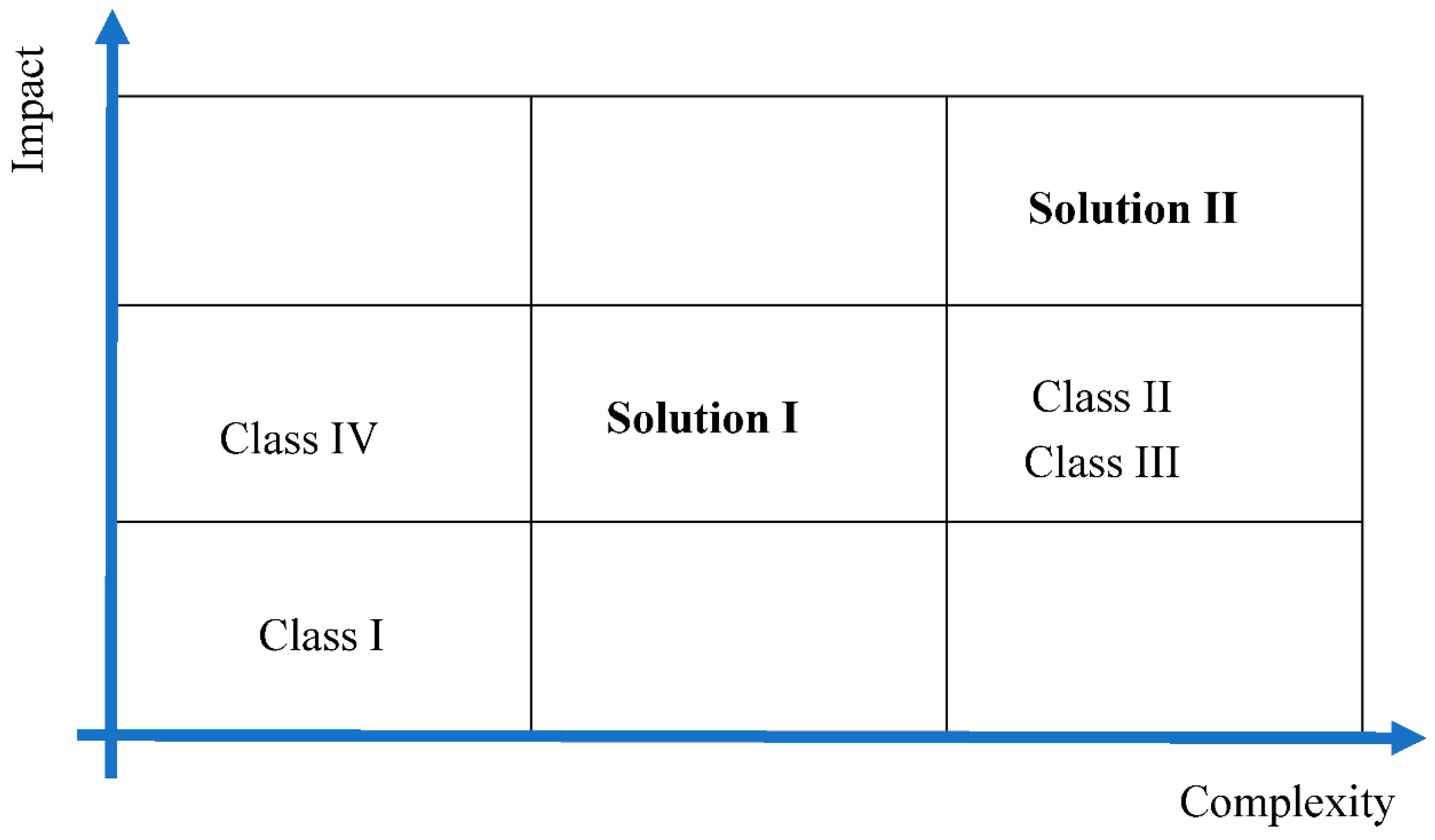
Associated with this classification, it is helpful to consider some form of evaluation and ranking of proposed solutions. For this purpose, it is worthwhile to analyse the complexity-impact (CI) correlation which is a practical index in selecting the feasible approach for dealing with challenges [63,64,65]. It is an assessment to value the effort that should be spend on a problem with respect to impacts of the results. Based on whole review, analyses and discussion presented so far, Figure 10 summarizes the development classes and proposed solutions with their CI index.
- Class I. Classic development is a straightforward approach with low complexity. However, it is not expected that it could have a great impact on TMS efficiency for the future engines.
- Classes II and III. Centralized and revolutionary developments are complicated approaches in formulation and implementation. If they are successful, they would impact the TMS sector noticeably.
- Class IV. Cost-effective development is also directed towards design and implement and if the basic idea has great potential, the impact would be noticeable as well.
Potential Solutions:
- (1)
- Solution I will promote the effectiveness of class I by combining it with class II of development
- (2)
- Solution II will promote classes II and III to achieve more impact to the TMS development in aerospace sector.
Both solutions are lying on the diagonal direction of the CI matrix which makes sense from computational effort and cost compensation points of view and introduce them as practical solutions to deal with the TMS challenges of the future aircraft engines.
6. Conclusions
A comprehensive historical review on design and development of thermal management systems for aircraft engines has been covered to identify the future challenges, opportunities and potential solutions for dealing with extra heats caused by advanced next generation of aircraft engines. The new ideas and approaches to enhance the TMS performance have been categorized in four different classes: classic, centralized, revolutionary and cost-effective developments. Each of these classes has its own pros and cons and will be faced with practical challenges in the development phase. Future engines involving more electric components will need the development of more sophisticated methods to deal with the extra heat. Consequently, two potential solutions have been proposed to deal with these challenges in the future:
- (1)
- Combination of classes I (classic) and IV (cost-effective) to cope with much more extra heat generated by new advanced and geared turbofan engines with power gearbox,
- (2)
- Combination of classes II (centralized) and III (revolutionary) to deal with needs for energy management in the system and focusing on new smart components for more advanced smart thermal management systems.
Author Contributions
Conceptualization, Methodology, Investigation, S.J. and T.N.; Writing-Original Draft Preparation, S.J.; Writing-Review & Editing, T.N.
Funding
This research received no external funding.
Conflicts of Interest
The authors declare no conflict of interest.
References
- Darecki, M.; Edelstenne, C.; Enders, T.; Fernandez, E.; Hartman, P.; Herteman, J.P.; Kerkloh, M.; King, I.; Ky, P.; Mathieu, M.; et al. Flightpath 2050, Europe’s Vision for Aviation Maintaining Global Leadership & Serving Society’s Needs; Report of the High Level Group on Aviation Research, Directorate-General for Research and Innovation Directorate-General for Mobility and Transport; Publications Office of the European Union: Brussels, Belgium, 2011. [Google Scholar]
- Han, J.C. Recent Studies in Turbine Blade Cooling. Int. J. Rotat. Mach. 2004, 10, 443–457. [Google Scholar] [CrossRef]
- Xu, L.; Bo, S.; Hongde, Y.; Lei, W. Evolution of Rolls-royce Air-cooled Turbine Blades and Feature Analysis. Procedia Eng. 2015, 99, 1482–1491. [Google Scholar] [CrossRef]
- Sunden, B.; Xie, G. Gas Turbine Blade Tip Heat Transfer and Cooling: A Literature Survey. Heat Transf. Eng. 2010, 31, 527–554. [Google Scholar] [CrossRef]
- Zheng, H.; Qi, L.; Zhao, N.; Li, Z.; Liu, X. A Thermodynamic Analysis of the Pressure Gain of Continuously Rotating Detonation Combustor for Gas Turbine. Appl. Sci. 2018, 8, 535. [Google Scholar] [CrossRef]
- Anindya, G.; Muthuvel, M.; Michael, J.W.; Andy, N.; Blake, D.B.; Marc, S.P.; Jeffrey, J.S.; Dongming, Z.; Kevin, A.K.; Christopher, R.R.; et al. Molten Particulate Impact on Tailored Thermal Barrier Coatings for Gas Turbine Engine. J. Eng. Gas Turbines Power 2017, 140, 022601. [Google Scholar] [CrossRef]
- Jafari, S.; Dunne, J.F.; Langari, M.; Yang, Z.; Pirault, J.-P.; Long, C.A.; Thalackottore Jose, J. A review of evaporative cooling system concepts for engine thermal management in motor vehicles. Proc. Inst. Mech. Eng. Part D 2016, 231, 1126–1143. [Google Scholar] [CrossRef] [Green Version]
- Lu, G.; Wang, F.; Di Mare, L.; Moss, M.; May, G. Data re-use for preliminary thermal-mechanical design of gas turbine engines. Aeronaut. J. 2018, 122, 462–486. [Google Scholar] [CrossRef]
- Gupta, M.; Markocsan, N.; Rocchio-Heller, R.; Liu, J.; Li, X.H.; Östergren, L. Failure Analysis of Multilayered Suspension Plasma-Sprayed Thermal Barrier Coatings for Gas Turbine Applications. J. Therm. Spray Technol. 2018, 27, 402–411. [Google Scholar] [CrossRef] [Green Version]
- Ma, X.; Ruggiero, P. Practical Aspects of Suspension Plasma Spray for Thermal Barrier Coatings on Potential Gas Turbine Components. J. Therm. Spray Technol. 2018, 27, 591–602. [Google Scholar] [CrossRef]
- Jafari, S.; Dunne, J.F.; Langari, M.; Yang, Z.; Pirault, J.P.; Long, C.A.; Thalackottore Jose, J. Control of Spray Evaporative Cooling in Automotive Internal Combustion Engines. J. Therm. Sci. Eng. Appl. 2018, 10, 041011. [Google Scholar] [CrossRef]
- Ljubas, D.; Krpan, H.; Matanovic, I. Influence of engine oils dilution by fuels on their viscosity, flash point and fire point. NAFTA 2010, 61, 73–79. [Google Scholar]
- Whurr, J. Future Civil Aero-engine Architectures & Technologies. In Rolls-Royce Future Programmes Report; Rolls-Royce PLC: Derby, UK, 2013. [Google Scholar]
- Spittle, P. Gas turbine technology. Phys. Educ. 2003, 38, 504. [Google Scholar] [CrossRef]
- Wang, Y.; Shah, N.; Huffman, G.P. Pure Hydrogen Production by Partial Dehydrogenation of Cyclohexane and Methylcyclohexane over Nanotube-Supported Pt and Pd Catalysts. Energy Fuels 2004, 18, 1429–1433. [Google Scholar] [CrossRef]
- Ganev, E.; Koerner, M. Power and Thermal Management for Future Aircraft; 13ATC-0280; SAE Technical Paper 2013-01-2273; SAE: Warrendale, PA, USA, 2013. [Google Scholar]
- Cumpsty, N. Jet Propulsion: A Simple Guide to the Aerodynamic and Thermodynamic Design and Performance of Jet Engines; Cambridge University Press: Cambridge, UK, 2012; ISBN 978-0-51-180941-5. [Google Scholar]
- Marshall, E.V. Oil Cooling and Drag Reducing System. U.S. Patent 2,865,530, 23 December 1958. [Google Scholar]
- Cummings, R.; Berea, L.; George, M. Engine Lubricating Oil Cooling Systems for Turbojets or the Like. U.S. Patent 3,080,716, 12 March 1963. [Google Scholar]
- Noddings, C.R.; Kelly, J.A. Endothermic Fuel System for Air Breathing Aircraft. U.S. Patent 3,438,602, 15 April 1969. [Google Scholar]
- Lavash, J.P. Fuel Delivery and Control System for a Gas Turbine Engine. U.S. Patent 3,779,007, 18 December 1973. [Google Scholar]
- Coffinberry, G.A.; Kast, H.B. Oil Cooling System for a Gas Turbine Engine. U.S. Patent 4,020,632, 3 May 1977. [Google Scholar]
- Frosch, R.A. Cooling System for High Speed Aircraft. U.S. Patent 4,273,304, 16 June 1981. [Google Scholar]
- Mayer, A.O.H. Heat Management System for Aircraft. U.S. Patent 4,505,124, 19 March 1985. [Google Scholar]
- Cornell, R.W.; Rohrbach, C. Multi-Bladed High Speed Drop Fan. U.S. Patent 4,171,183, 16 October 1979. [Google Scholar]
- Burr, D.N.; Danilowicz, P.S.; Franz, T.C.; Mortimer, T.P.; Pew, E.B. Fuel and Oil Heat Management System for a Gas Turbine Engine. U.S. Patent 4,696,156, 29 September 1987. [Google Scholar]
- Elovic, E. Cooling Air Cooler for a Gas Turbofan Engine. U.S. Patent 4,254,618, 10 March 1981. [Google Scholar]
- Griffin, J.G.; Schwarz, F.M. Cooling System for the Electrical Generator pf a Turbofan Gas Turbine Engine. U.S. Patent 4,474,001, 2 October 1984. [Google Scholar]
- Mortimer, T.P.; Suciu, G.L. Heat Exchange System. U.S. Patent 4,546,605, 15 October 1985. [Google Scholar]
- Hudson, W.A.; Levin, M.L. Integrated Aircraft Fuel Thermal Management System. U.S. Patent 4,776,536, 11 October 1988. [Google Scholar]
- Dennison, W.T.; Brodell, R.F. Nose Cowl Mounted Oil Lubricating and Cooling System. U.S. Patent 4,722,666, 2 February 1988. [Google Scholar]
- Geidel, H.; Rohra, A. Propfan Turbine Engine. U.S. Patent 4,887,424, 19 December 1989. [Google Scholar]
- Riid, K.; Rohra, A. Turbo Engine. U.S. Patent 4,999,994, 19 March 1991. [Google Scholar]
- Edwards, W.H. Inhibiting Coke Formation by Coating Gas Turbine Elements with Alumina. U.S. Patent 5,264,244, 23 November 1993. [Google Scholar]
- Bruening, G.B.; Chang, W.S. Cooled cooling air systems for turbine thermal management. In Proceedings of the ASME International Gas Turbine & Aeroengine Congress & Exhibition, Indianapolis, IN, USA, 7–10 June 1999; ISBN 978-0-7918-7860-6. [Google Scholar]
- Huang, H.; Spadaccini, L.J.; Sobel, D.R. Fuel-cooled thermal management for advanced aero engines. In Proceedings of the ASME TURBO EXPO 2002, Amsterdam, The Netherlands, 3–6 June 2002; pp. 367–376. [Google Scholar]
- Ely, J.F.; Huber, M.L. NIST Standard Reference Database 4—NIST Thermo-Physical Properties of Hydrocarbon Mixtures; National Institute of Standards and Technology: Gaithersburg, MD, USA, 1990.
- Spadaccini, L.J.; Colket, M.B.; Marteney, P.J.; Roback, R.; Glickstein, M.R.; Stiles, A.B. Endothermic Fuel/Catalyst Development and Evaluation—Phase I; AFWRDC-TR-89-2141; United Technology Research Centre: East Hartford, CT, USA, 1993. [Google Scholar]
- Spadaccini, L.J.; Sobel, D.R.; Colket, M.B.; Marteney, P.J.; Glickstein, M.R. Endothermic Fuel/Catalyst Development and Evaluation Phases II, III and IV; AFWL-TR-91-2126; United Technology Research Centre: East Hartford, CT, USA, 1993. [Google Scholar]
- Sobel, D.R.; Spadaccini, L.J. Hydrocarbon Fuel Cooling Technologies for Advanced Propulsion. J. Eng. Gas Turbines Power 1997, 119, 344–351. [Google Scholar] [CrossRef]
- Kim, J.; Park, S.H.; Chun, B.H.; Kim, S.H.; Jeong, B.H.; Han, J.S. A Technical Review of Endothermic Fuel Use on High Speed Flight Cooling. J. Korean Soc. Propul. Eng. 2010, 14, 71–79. [Google Scholar]
- Mahefkey, T.; Yerkes, K.; Donovan, B.; Ramalingam, M.L. Thermal management challenges for future military aircraft power systems. In Proceedings of the Power System Conference, Reno, NV, USA, 2–4 November 2004. [Google Scholar]
- Ronald, S.B. Gas Turbine Heat Transfer: Ten Remaining Hot Gas Path Challenges. J. Turbomach. 2007, 129, 193–201. [Google Scholar]
- Adam, C.M.; Elena, G.; Dimitri, M. Thermal Management Modeling for Integrated Power Systems in a Transient, Multidisciplinary Environment. In Proceedings of the 45th AIAA/ASME/SAE/ASEE Joint Propulsion Conference & Exhibit, Denver, CO, USA, 2–5 August 2009. [Google Scholar]
- Federico, P. Gas Turbine Engine Thermal Management System; EP 2 587 024 A2; United Technologies Corporation: Hartford, CT, USA, 2012. [Google Scholar]
- Suciu, G.L.; Pickford, S.; Ackermann, W.A.; Snape, N.; Hipsky, H.W. Turbomachinery Thermal Management. U.S. Patent 2013/0259687 A1, 3 October 2013. [Google Scholar]
- Niggemann, R.E.; Ngyuyen, D. Thermal and Energy Management Method and Apparatus for an Aircraft. U.S. Patent 6,182,435 B1, 6 February 2001. [Google Scholar]
- Huang, H.; Kaslusky, S.E.; Tillman, T.G.; Sabatlno, D.R. System Method for Thermal Management. U.S. Patent 6,939,392 B2, 6 September 2005. [Google Scholar]
- Suciu, G.L.; Norris, J.W. Turbine Engine Rotor Stack. U.S. Patent 7,309,210 B2, 18 December 2007. [Google Scholar]
- Walter Smith, J. Systems and Methods for Thermal Management in a Gas Turbine Power Plant. U.S. Patent 8,534,044 B2, 17 September 2013. [Google Scholar]
- Sousa, J.; Villafañe, L.; Paniagua, G. Thermal analysis and modelling of surface heat exchangers operating in the transonic regime. Energy 2014, 64, 961–969. [Google Scholar] [CrossRef]
- Brandon Wayne, M. Gas Turbine Engine Thermal Management System. U.S. Patent 0,208,698 A1, 21 July 2016. [Google Scholar]
- Peltokoski, R. Heat Exchangers for Thermal Management Systems. European Patent EP 3 054 126 A1, 2 September 2016. [Google Scholar]
- Teicholz, M.D.; Stearns, E.K. Technique for Optimizing Engine Performance Using Fuel Temperature. U.S. Patent 0,332,743 A1, 17 November 2016. [Google Scholar]
- Bracey, M.J. Dynamic Modelling of Thermal Management System with Exergy Based Optimization. Master’s Thesis, Wright State University, Dayton, OH, USA, 2016. [Google Scholar]
- Sibilli, T. Heat Exchange System for a Power Gearbox, a Power Gearbox and a Turbo Engine with a Power Gear Box. European Patent EP3244039 A1, 22 June 2017. [Google Scholar]
- Pececnik, J. Oscillating Heat Pipe for Thermal Management of Gas Turbine Engines. U.S. Patent 2014/0165570 A1, 19 June 2014. [Google Scholar]
- Vaisman, I.; Gagne, S.T.; Burkholder, K. Thermal Management System Controlling Dynamic and Steady State Thermal Loads. U.S. Patent 2018/0045432 A9, 15 February 2018. [Google Scholar]
- Mossey, R. Innovations Drive Weight and Emission Reductions for Aircraft Engines, 14 June 2017. Available online: http://blog.parker.com/innovations-drive-weight-and-emission-reductions-for-aircraft-engines (accessed on 14 June 2017).
- Abraham Karam, M. Gas Turbine Engine with Air/Fuel Heat Exchanger. U.S. Patent 9,771,867 B2, 26 September 2017. [Google Scholar]
- Jain, N.; Hencey, B.M. Increasing Fuel Thermal Management System Capability via Objective Function Design. In Proceedings of the 2016 American Control Conference (ACC) Boston Marriott Copley Place, Boston, MA, USA, 6–8 July 2016. [Google Scholar]
- Parker White Paper, Selecting a Thermal Management System Supplier for Aerospace and Defence Applications, Posted by Aerospace Team on Tuesday, 29 August 2017. Available online: http://blog.parker.com/selecting-a-thermal-management-system-supplier-for-aerospace-and-defense-applications (accessed on 29 August 2017).
- Construction Industry Institute (CII). Research Summary 305-1; CII: Austin, TX, USA, 2015. [Google Scholar]
- Construction Industry Institute (CII). Research Report 305-11; CII: Austin, TX, USA, 2015. [Google Scholar]
- Cicmil, S.; Cooke-Davis, T.; Crawford, L.; Richardson, K. Exploring the Complexity of Projects: Implications of Complexity Theory for Project Management Practice; Project Management Institute: Newtown Square, PA, USA, 2009. [Google Scholar]
Figure 1.
Thermal management system embodiments proposed by United Technologies Corporation.
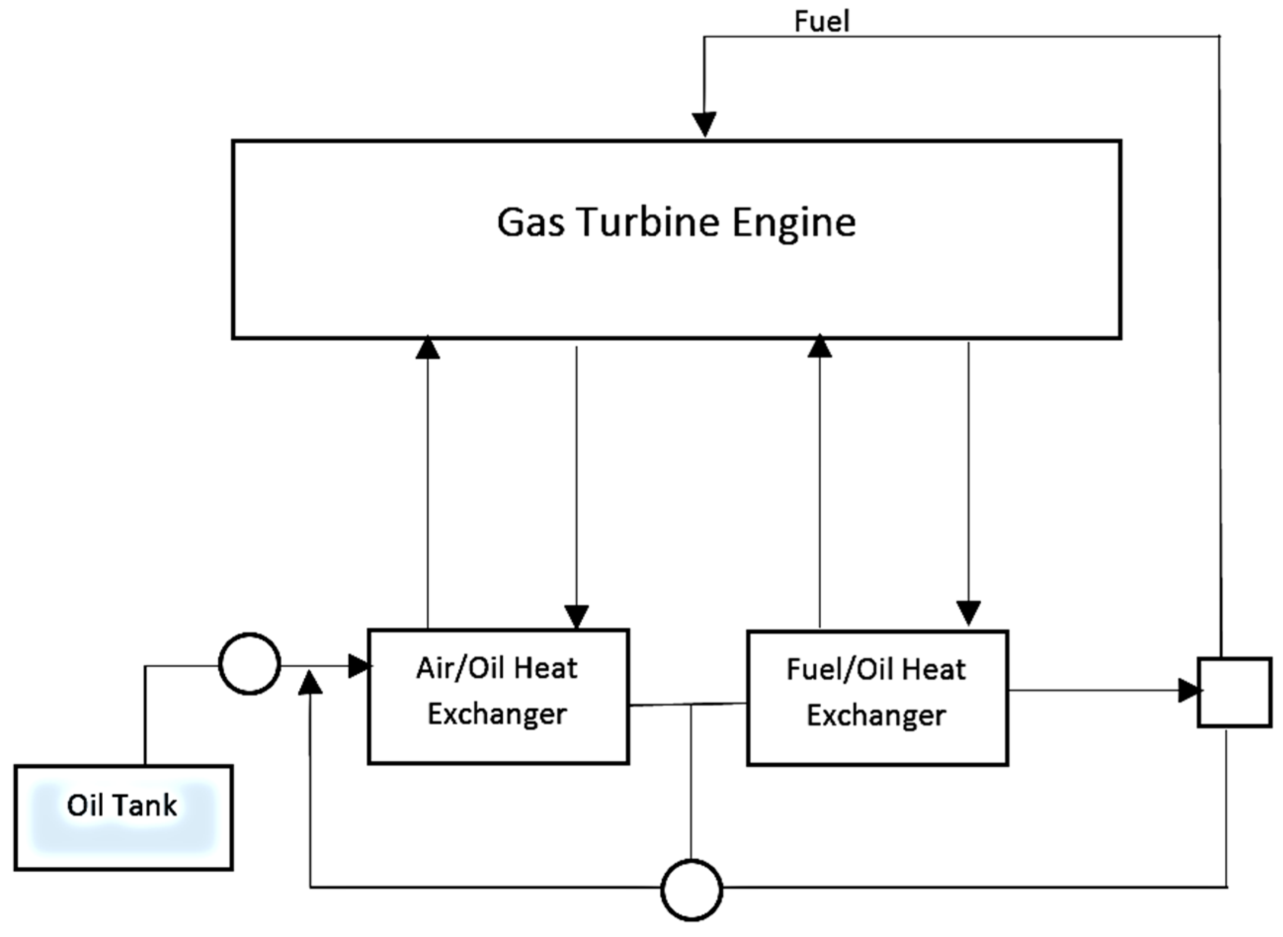
Figure 2.
CCA concept using a Fuel-to-Air Heat Exchanger Concept.

Figure 3.
Thermal management system embodiments with different temperature loops proposed by United Technologies Corporation.
Figure 3.
Thermal management system embodiments with different temperature loops proposed by United Technologies Corporation.

Figure 4.
Thermal management system embodiments with two heat exchangers and using bypass air (EOL: Engine Oil Line, BPA: Bypass Air).
Figure 4.
Thermal management system embodiments with two heat exchangers and using bypass air (EOL: Engine Oil Line, BPA: Bypass Air).
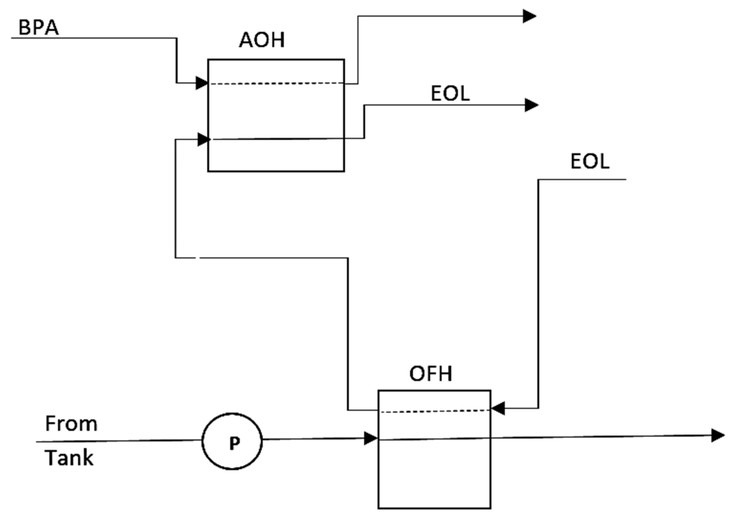
Figure 5.
Thermal management system embodiments with two heat exchangers and recirculation path.
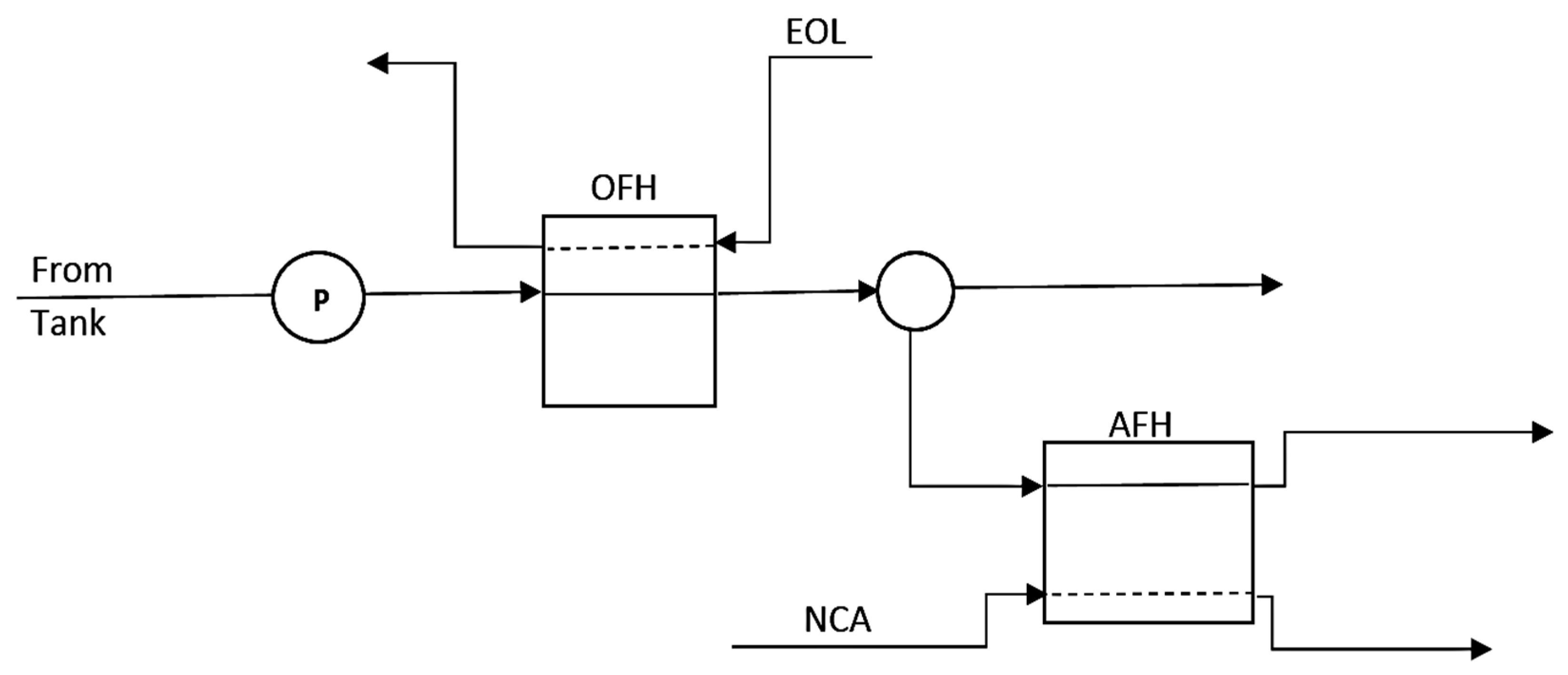
Figure 6.
Thermal management system embodiments with separate line heat exchangers for geared systems.
Figure 6.
Thermal management system embodiments with separate line heat exchangers for geared systems.
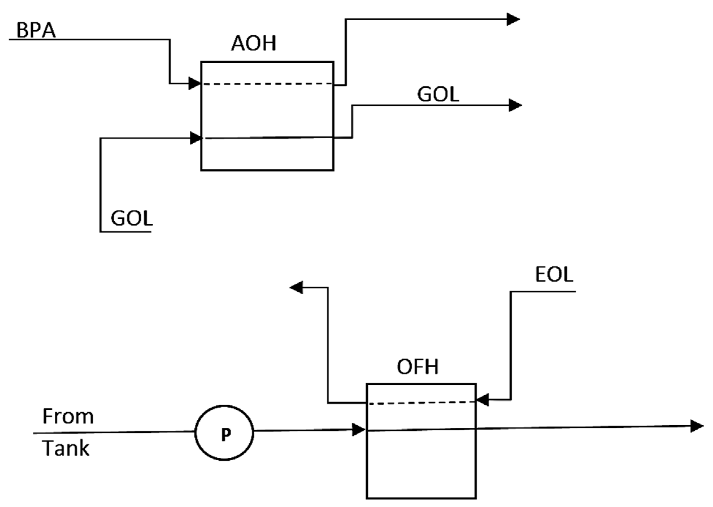
Figure 7.
Thermal management system embodiments with working fluid and reversible pump. FWD: Forward, Rev: Reverse.
Figure 7.
Thermal management system embodiments with working fluid and reversible pump. FWD: Forward, Rev: Reverse.

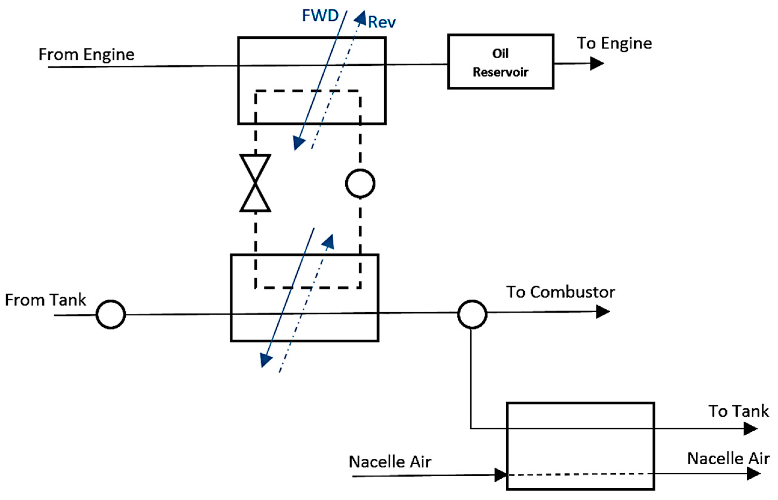
Figure 8.
Thermal management system embodiments with thermally neutral heat transfer fluid.

Figure 9.
Thermal management system embodiments with thermally neutral heat transfer fluid for cooling the compressor bleed air.
Figure 9.
Thermal management system embodiments with thermally neutral heat transfer fluid for cooling the compressor bleed air.

Figure 10.
CI analysis of development classes and proposed solutions.

| Thrust (lbf) | Turbine Entry Temperature (°C) | Bypass Ratio | Turbine Blade Cooling Efficiency | |
|---|---|---|---|---|
| Phase I | ≤40,000 | ≤1200 | ≤5 | ≤0.55 |
| Phase II | 40,000–55,000 | 1200–1400 | 5–7.6 | 0.55–0.65 |
| Phase III | ≥55,000 | ≥1400 | ≥8 | ≥0.65 |
Table 2.
Drawbacks of the classes of TMS development for the future aero-engines.
| Class of Development | Main Drawbacks | |
|---|---|---|
| I | Classic |
|
| II | Centralized |
|
| III | Revolutionary |
|
| IV | Cost-effective |
|
© 2018 by the authors. Licensee MDPI, Basel, Switzerland. This article is an open access article distributed under the terms and conditions of the Creative Commons Attribution (CC BY) license (http://creativecommons.org/licenses/by/4.0/).
Share and Cite
MDPI and ACS Style
Jafari, S.; Nikolaidis, T. Thermal Management Systems for Civil Aircraft Engines: Review, Challenges and Exploring the Future. Appl. Sci. 2018, 8, 2044. https://doi.org/10.3390/app8112044
AMA Style
Jafari S, Nikolaidis T. Thermal Management Systems for Civil Aircraft Engines: Review, Challenges and Exploring the Future. Applied Sciences. 2018; 8(11):2044. https://doi.org/10.3390/app8112044
Chicago/Turabian StyleJafari, Soheil, and Theoklis Nikolaidis. 2018. "Thermal Management Systems for Civil Aircraft Engines: Review, Challenges and Exploring the Future" Applied Sciences 8, no. 11: 2044. https://doi.org/10.3390/app8112044
Note that from the first issue of 2016, this journal uses article numbers instead of page numbers. See further details here.