2D Micromechanical Modeling and Simulation of Ta-Particles Reinforced Bulk Metallic Glass Matrix Composite


State Key Laboratory of Mechanics and Control of Mechanical Structures, Nanjing University of Aeronautics and Astronautics, Nanjing 210026, China
*
Author to whom correspondence should be addressed.
Appl. Sci. 2018, 8(11), 2192; https://doi.org/10.3390/app8112192
Submission received: 29 September 2018
/
Revised: 2 November 2018
/
Accepted: 5 November 2018
/
Published: 8 November 2018
(This article belongs to the Special Issue Computational Methods for Fracture)
Abstract
:The influence of particle shape, orientation, and volume fractions, as well as loading conditions, on the mechanical behavior of Ta particles reinforced with bulk metallic glass matrix composite is investigated in this work. A Matlab program is developed to output the MSC.Patran Command Language (PCL) in order to generate automatically two-dimensional (2D) micromechanical finite element (FE) models, in which particle shapes, locations, orientations, and dimensions are determined through a few random number generators. With the help of the user-defined material subroutine (UMAT) in ABAQUS, an implicit numerical method based on the free volume model has been implemented to describe the mechanical response of bulk metallic glass. A series of computational experiments are performed to study the influence of particle shapes, orientations, volume fractions, and loading conditions of the representative volume cell (RVC) on its composite mechanical properties.
1. Introduction
Bulk metallic glass (BMG) as an amorphous alloy has attracted much attention due to its extreme high strengths, superior elastic limits, etc. [1]. Although there has been much progress in the development of metallic glass with the development of manufacturing technologies, unlike common alloy, BMGs show nearly no ductility under loading at room temperature, which severely limits their structural application [2,3]. The micromechanical research shows that the plastic deformation localization is the main reason for brittle failure [4,5].
In order to avoid the brittle failure and improve the ultimate plastic extensibility of BMGs, metallic glass matrix composites (MGMCs) were firstly synthesized at the California Institute of Technology (Caltech) in the United States (USA) in 1998 [6,7]. A “soft” second phase, which has lower yield stress than BMGs, has been introduced for particle-reinforced composite [8]. Unlike pure BMGs, the second reinforced phase can block the propagation of the main shear band and generate a few of minor shear deformation zone, which can make the plastic deformation be distributed widely instead of the localization that is seen in pure BMGs [9,10]. The secondary phases themselves can absorb the plasticity, and profuse shear bands induced by the secondary phases can accommodate more plasticity [11].
Generally, the macroscopic response of MGMCs is some kind of statistical average of the microstructural factors, such as particle volume fraction, shape, orientation, and spatial spacing, as well as interface strength and residual stress, etc. It is extremely expensive and time-consuming, if it is not impossible, to establish the relationship between the macroscale mechanical properties of MGMCs and their microscale structures through either the experimental method or theoretical analysis. A number of computational models have been developed to predict the MGMCs’ mechanical behaviors. Different numerical methods, including the molecular dynamics method [12,13,14] and phase-field method [15,16], as well as the finite element method (FEM) [17,18,19,20,21,22,23] are utilized to reveal the deformation mechanisms at the microscale.
Shi and Falk [12] identified the location of the plastic deformation, the deformation mechanism of the crystallites, and the interaction between the shear band and the crystalline inclusions through the molecular dynamics method. Albe et al. [13] applied the molecular dynamics method to study the shear band formation in homogenous bulk metallic glasses, nanocomposites, and nanoglasses. Zhou et al. performed a comprehensive study of the structural evolution of MGMCs through large-scale atomistic simulations [14]. The simulation results showed that slender crystalline second phases are better at suppressing shear band propagation than those with spherical shapes, and that increasing the volume fraction of the crystalline second phase will enhance the global plasticity. Abdeljawad et al. applied a two-dimensional (2D) phase-field model to examine the effects of BMG composite microstructures, e.g., the area fraction and the characteristic length scale of the ductile dendritic particles, on the mechanical properties of MGMCs [15]. Zhang and Zheng applied the phase-field simulation approach to investigate the formation mechanisms of shear bands in MGMCs containing dendrite particles [16].
Compared with molecular dynamics and phased field approaches, finite element analysis is more widely employed to investigate the mechanical behavior of MGMCs. Ott et al. [17] examined the microscale deformation mechanisms of MGMCs under uniaxial compression, combining high-energy X-ray scattering and finite element modeling. Lee et al. [18] investigated the effect of the crystalline phase on shear band initiation, interaction, and propagation in MGMCs with a unit finite element model. Biner [19] studied the influences of the mechanical properties, volume fraction, and morphology of ductile reinforcements on the ductility of MGMCs. Wu et al. [20] studied the influence of sample dimension on the toughness of MGMCs through scaling a microscale finite element model. Zhu et al. revealed that the plastic deformation of reinforced particles creates a shear stress concentration on the interface, and shear stress distribution leads to the formation of multiple shear bands through a combination of in situ SEM observations and finite element simulation [21]. Qiao et al. [22] quantitatively described the macroscopic MGMC deformation mechanics through a two-phase finite element model. The simulation of Hardin and Homer [23] showed that increasing the volume fraction alone is insufficient to promote strain delocalization in the case of a crystalline phase with a high relative yield stress, which is different from the results of Zhou et al. [14]. Jiang et al. [24,25] applied finite element methods to analyze the shear banding evolution and elucidate the relationship between the microstructure and ductility of MGMCs subjected to uniaxial tension. Unlike the results of Zhou et al. [14], they found that the particle shape has almost no effect in improving the tensile ductility of MGMCs. In addition, network second-phase was reported to be more efficient in improving the extensibility of composites [26].
Although there are many studies on the microscale deformation mechanism of MGMCs, it is still far away from a complete and thorough understanding of fundamental synergic mechanisms. For example, there are two contradictions in the literature about the influence of particle volume fraction and shape on the toughening mechanism of MGMCs [14,22,25]. Therefore, more detailed study is necessary in order to clarify the effect of the microstructure on the mechanical response of MGMCs. In this work, we study the influence of the microstructures and loading conditions on the mechanical properties of MGMCs through the periodic boundary conditions, which are realized with a multi-point constraint subroutine MPC in ABAQUS. The different kinds of shapes have been simplified to ellipses with different respect ratios. A program based on Matlab has been developed to generate ellipses with a random distribution of locations and orientations. The nodes and elements are generated with MSC.Patran and a free volume constitutive model for bulk metallic glasses is implied with the user-defined material (UMAT) in ABAQUS. A series of numerical studies are performed to analyze the influence of particle volume, shape, and orientation, as well as the loading conditions on the macroscopic stress–strain relationships and damage evolution in MGMCs.
2. Micromechanical Finite Element Model
2.1. Automatic Generation of the Representative Elementary Cell (RVC)
It is commonly recognized that the microstructure of the composite plays an important role in the macroscale response. Therefore, in order to study the effect of the microstructure on its deformation and failure process, the microstructure of the composite material under consideration should be able to vary according to the requirement. Here, the microstructure contains the randomly distributed elliptic particles with different shapes, but the same area is controlled through a few random number generators.
It’s assumed that the RVC of the composite microstructure is a square with length of L0, and the particle number and area fraction are np and vp, respectively. Therefore, the area of each particle can be expresses as:
Notice that the area of ellipse with the lengths of the semi-major and semi-minor axes ( and , i = 1, 2, …, np) can be expressed as:
A random number stream controlled by the generator seed s1 is introduced to define the shape ratio between the lengths of two semi-axes:
Meanwhile, another random number stream Rand2 controlled by random number generator seed s2 is applied to define the alignment of each particle:
The particle centers are determined independently and sequentially with two random number streams (Rand3 and Rand4) that are controlled by two random number generator seeds (s3 and s4). If an introduced particle cuts any of the RVC boundaries, the particle is copied to the opposite side of the square unit, as shown in Figure 1. Furthermore, the introduced particle should not be too close to the square boundaries or the existing particles. An iteration algorithm [27] is applied to calculate the distance between two elliptic particles, and is schematically shown in Figure 2. If any condition above is not met, the location of the new particle is determined by the next random number.
A Matlab program is developed to realize the above algorithm, and after running the Matlab program, a command file for the commercial software MSC/Patran can be obtained. A 2D microstructural finite element model with predefined parameters, such as the volume fraction and number of particles, mesh dimension, and so on, can be obtained through playing the command file with MSC/Patran. A multi-point constraint subroutine MPC in ABAQUS is developed to apply periodic boundary conditions (PBC) [28,29].
2.2. Constitutive Response of Ta Particles and BMGs
So far, several constitutive models are developed to describe the deformation of the BMGs. Argon proposed the shear transformation model using Eshelby’s insightful theory, in which he assumes that the plastic deformation only occurs in the region called the shear transformation zone [30]. Furthermore, Jiang et al. developed a tension transformation zone model to describe the quasi-brittle dilatation deformation in metallic glass [31]. Viewing the basic “flow event” as an individual atom jump driven by the shear stress, Spaepem [32] developed the free volume model to analyze the plastic deformation in the BMGs. Compared other constitutive models, the free volume model has a clear physical meaning, and has been widely used to evaluate the mechanical properties of the BMGs.
According to Spaepem, the general free volume model flow equation is written as:
where is the frequency of atomic vibration, is a geometrical factor, is the critical volume, is the average free volume per atom, is the activation energy, is the atomic volume, is the shear stress, is the Boltzmann constant, and is the absolute temperature. Unlike the equivalent plastic strain in the usual metal plastic model, the free volume is used as a parameter to describe plastic deformation. The net rate of the free-volume increase is:
Here is a constant varying from three to 10. is the effective elastic module for isotropic materials with Young’s modulus and Poisson’s ratio .
According to the flow rule, the strain can be decomposed into elastic and plastic parts:
Moreover, the elastic and plastic strain rate can be expressed as follows:
where is the deviatoric stress tensor, and is the equivalent stress. According to the flow rule, the evolution of plastic strain is a function depending on the deviatoric stress. So, the flow equation can be written as follows:
in which, is the reference stress, and and are the normalized free volume. A user-defined material subroutine (UMAT) in ABAQUS code is developed to implement the free-volume model [33].
For reinforcing Ta particles, an exponentiation isotropic hardening relationship according to Zhang et al. [16] has been used to describe the plastic deformation in the crystal metal here:
where is the reference plastic strain, is the hardening exponent, and is the yield stress under uniaxial loading. is the equivalent strain, and is defined by:
3. Simulation Results and Discussion
3.1. Verification of Numerical Model
To verify the basic property of mechanics, a RVC reinforced by a 10% volume fraction of identical circle particles is generated through the developed Matlab program. The uniaxial compressive load along the y-axis is applied, and the strain rate of applied load in this paper is fixed to be 0.0005/s. Figure 3A shows the nominal stress–strain response of the MGMC and pure BMG model, and Figure 3B show the distribution of equivalent plastic strain in BMG corresponding to point (I–IV) in Figure 3A. It can be seen from Figure 3 that the stiffness of the MGMC is a bit higher than that of the BMG, and obviously, the MGMC has better ductile property than pure BMG. Furthermore, there are four distinguishable stages in the process of the composite deformation, which is different from that of the BMGs. In first stage from the loading start to point (I), there is only elastic deformation in both the BGM matrix and Ta particles. In the second stage from point (I) to point (II), Ta particles enter the plastic deformation, while BMG is still in an elastic state. In the third stage from point (II) to point (III), both the matrix and particles deform with plastic strain. However, the response compressive stress is kept nearly as a constant, which is different from the steep descent of a pure BMG specimen. The main shear band in BMG is blocked by soft particles because plastic deformation is “absorbed” by them. The steep stress fall occurs in the fourth stage from point (III) to point (IV). The main shear band penetrates whole RVC, and both the particles and the matrix slide along it. As a result, the MGMC loses the load capacity.
3.2. Effects of Particle Orientation
In this subsection, the influence of particle orientation varying between 0 degrees, 22.5 degrees, and 45 degrees related to the x-axis on the mechanical properties of MGMCs with a 25% particle volume fraction is studied under uniaxial compressive loading along the y-axis. Five different microstructural finite element models with a constant particle shape ratio of two are generated through the developed program for different particle orientations, respectively. It can be seen from Figure 4 that the particle orientation plays a small role on the stiffness of the MGMC, while the strength of the MGMCs increases with the increase of particle orientation. Meanwhile, when MGMCs enter the yield stages, the hardening stages increase with the increase of the particle orientation angle. Zero-degree orientation will cause biggest stress concentration among the three different orientations; thus, there is much more plastic deformation in MGMCs with zero-degree particle arrangement than those with 45 degrees, as shown in Figure 5. From Figure 5, one can also see that the particles in MGMCs block the propagation of shear bands in BMG.
3.3. Effects of Particle Shape
In this subsection, the influence of particle shape varying between one (circular particle), two, and three on the mechanical properties of MGMCs with a 25% particle volume fraction is studied under uniaxial compressive loading along the y-axis. Five different microstructural finite element models containing ellipse particles with random orientation are generated through the developed program for different particle shapes, respectively. It can be seen from Figure 6 that particle shape plays a small role on the stiffness and strength of MGMCs. However, circle particles can bring more ductility than ellipse particles. The extensibility brought by particles decreases with the increasing aspect ratio of the particle. In Figure 7, it can be seen that the shear band is always generated from the tips of ellipses. Particles that have a large respect ratio may have more stress concentration and stress misfit, which will promote the generation of shear bands.
3.4. Effects of Volume Fraction
In this subsection, the influence of particle volume fraction ranging between 15%, 25%, and 35% on the mechanical properties of MGMCs is studied under uniaxial compressive loading along the y-axis. Five different microstructural finite element models containing ellipse particles with random orientations and shapes are generated through the developed program for different particle volume fractions, respectively. It can be seen from Figure 8 that the volume fraction of the particle plays a small role on the stiffness of MGMCs, because the Ta particle and BMG have almost the same stiffness. When an MGMC containing 15% particles reaches the yield stress, the nominal stress decreases slowly for about 4% strain, and then loses its carrying capacity rapidly. In other words, the yield stress of an MGMC with 15% particles is also its strength. When an MGMC containing 35% particles reaches the yield stress, a hardening stage can be clearly seen with the increase of the loading. Shear bands intersect with each other and generate major and minor bands. The composites with 15 vol.% particles have the same shear band direction with pure BMGs due to the scale limitation of the particles in them. Nevertheless, the existing minor shear bands share plastic deformation with the major band. As a result, there will be no obvious difference between the different shear bands, which will improve the macroscopic ductility of the composites. Furthermore, with the increase of the particle volume fraction, shear bands cannot propagate in original direction because of the particle block. Ultimate shear bands are wavy, as shown in Figure 9.
3.5. Effects of Load Condition
The real shear band directions of propagation are determined by local stress. Therefore, unlike uniaxial compress, different load cases coupling compression and shear loading have been tested. The ratio between two kinds of loads is defined as . Here, the MGMC models with 25 vol.% particles that were generated in the previous subsection are adopted to study the influence of loading condition on the mechanical properties of MGMCs. The equivalent stress and strain are respectively defined as:
Figure 10 illustrates the relationship between equivalent stress and strain under different load conditions. Similarly, the load condition almost plays no role on the stress–strain relationship in the elastic stage. Nevertheless, the yield strengths decease with the increase of the shear part in the applied load. In addition, the ductility of MGMCs decreases with the increase of the shear part in the applied load. Figure 11 shows the plastic distribution of BMG in MGMCs under different load conditions. It can be seen from Figure 11 that with the decrease of the compressive part in the load, the direction of the main shear band approaches the y-axis.
4. Conclusions
A new method and a software code are developed for the automatic generation of two-dimensional (2D) micromechanical FE models of Ta particle-reinforced metallic glass matrix composite with a random distribution of elliptic shape and orientation, as well as location arrangement. A series of computational experiments are performed to study the influence of the microstructure of MGMC on its stiffness and strength properties. Four deformation stages can be distinguished during the external load: both particles and BMG are in elastic states, particles are in a plastic-hardening state while BMG is still in an elastic state, both particles and BMG are in plastic deformation states, and the diffuse shear band in BMG emerges into a main shear band, and MGMC loses its carrying capability. The following conclusions can be obtained from the computational experiments:
- A larger angle between the load axis and the particle orientation leads to better ductile properties for MGMCs.
- The extensibility of MGMCs decreases with the increase of the respect ratio of the particle. Meanwhile, particle shapes play a small role in the ultimate strength of MGMCs.
- Particles with higher volume fraction can bring a greater improvement of ductility, but less ultimate strength.
- The yield strengths decease with the increase of the shear part in the combined tensile and shear loading.
Author Contributions
Conceptualization, H.Q. and C.-F.G.; Methodology, P.-L.B. and H.Q.; Software, P.-L.B., T.-L.L. and H.Q.; Validation, P.-L.B., T.-L.L. and H.Q.; Formal Analysis, H.Q. and C.-F.G.; Investigation, P.-L.B. and T.-L.L.; Resources, P.-L.B. and T.-L.L.; Data Curation, P.-L.B. and H.Q.; Writing-Original Draft Preparation, P.-L.B.; Writing-Review & Editing, H.Q.; Visualization, P.-L.B., T.-L.L. and C.-F.G.; Supervision, H.Q. and C.-F.G.; Project Administration, H.Q.; Funding Acquisition, H.Q.
Funding
This research was funded by the National Natural Science Foundation of China grant number 11672131, the Research Fund of State Key Laboratory of Mechanics and Control of Mechanical Structures (Nanjing University of Aeronautics and Astronautics) grant number MCMS-0217G02, and the Priority Academic Program Development of Jiangsu Higher Education Institutions and the Scientific Research Foundation for the Returned Overseas Chinese Scholars, State Education Ministry.
Conflicts of Interest
The authors declare no conflicts of interest.
References
- Klement, W.; Willens, R.H.; Duwez, P. Non-crystalline Structure in Solidified Gold–Silicon Alloys. Nature 1960, 187, 869–870. [Google Scholar] [CrossRef]
- Qiao, J.; Jia, H.; Liaw, P.K. Metallic glass matrix composites. Mater. Sci. Eng. R-Rep. 2016, 100, 1–69. [Google Scholar] [CrossRef] [Green Version]
- Trexler, M.M.; Thadhani, N.N. Mechanical properties of bulk metallic glasses. Prog. Mater. Sci. 2010, 55, 759–839. [Google Scholar] [CrossRef]
- Chen, M. Mechanical Behavior of Metallic Glasses: Microscopic Understanding of Strength and Ductility. Annu. Rev. Mater. Res. 2008, 38, 445–469. [Google Scholar] [CrossRef]
- Zhang, Y.; Greer, A.L. Thickness of shear bands in metallic glasses. Appl. Phys. Lett. 2006, 89, 71907. [Google Scholar] [CrossRef]
- Hofmann, D.C.; Johnson, W.C. Bulk metallic glass matrix composites. Appl. Phys. Lett. 1997, 71, 3808–3810. [Google Scholar] [Green Version]
- Conner, R.D.; Dandliker, R.B.; Johnson, W.L. Mechanical properties of tungsten and steel fiber reinforced Zr41.25Ti13.75Cu12.5Ni10Be22.5 metallic glass matrix composites. Acta Mater. 1998, 46, 6089–6102. [Google Scholar] [CrossRef]
- Park, E.S.; Kim, D.H. Formation of Ca–Mg–Zn bulk glassy alloy by casting into cone-shaped copper mold. J. Mater. Res. 2004, 19, 685–688. [Google Scholar] [CrossRef]
- Chen, M.; Inoue, A.; Fan, C.; Sakai, A.; Sakurai, T. Fracture behavior of a nanocrystallized Zr65Cu15Al10Pd10 metallic glass. Appl. Phys. Lett. 1999, 74, 2131–2133. [Google Scholar] [CrossRef]
- Qiao, J.; Sun, A.C.; Huang, E.; Zhang, Y.; Liaw, P.K.; Chuang, C. Tensile deformation micromechanisms for bulk metallic glass matrix composites: From work-hardening to softening. Acta Mater. 2011, 59, 4126–4137. [Google Scholar] [CrossRef]
- Ma, X.Z.; Ma, D.Q.; Xu, H.; Zhang, H.Y.; Ma, M.Z.; Zhang, X.Y.; Liu, R.P. Enhancing the compressive and tensile properties of Ti-based glassy matrix composites with Nb addition. J. Non. Cryst. Solids 2017, 463, 56–63. [Google Scholar] [CrossRef]
- Shi, Y.; Falk, M.L. Strain localization and percolation of stable structure in amorphous solids. Phys. Rev. Lett. 2005, 95, 95502. [Google Scholar] [CrossRef] [PubMed]
- Albe, K.; Ritter, Y.; Şopu, D. Enhancing the plasticity of metallic glasses: Shear band formation, nanocomposites and nanoglasses investigated by molecular dynamics simulations. Mech. Mater. 2013, 67, 94–103. [Google Scholar] [CrossRef]
- Zhou, H.; Qu, S.; Yang, W. An atomistic investigation of structural evolution in metallic glass matrix composites. Int. J. Plast. 2013, 44, 147–160. [Google Scholar] [CrossRef]
- Abdeljawad, F.; Fontus, M.; Haataja, M. Ductility of bulk metallic glass composites: Microstructural effects. Appl. Phys. Lett. 2011, 98, 31909. [Google Scholar] [CrossRef]
- Zhang, H.; Zheng, G. Simulation of shear banding in bulk metallic glass composites containing dendrite phases. J. Alloys Compd. 2014, 586, S262–S266. [Google Scholar] [CrossRef]
- Ott, R.T.; Sansoz, F.; Molinari, J.; Almer, J.; Ramesh, K.T.; Hufnagel, T.C. Micromechanics of deformation of metallic-glass-matrix composites from in situ synchrotron strain measurements and finite element modeling. Acta Mater. 2005, 53, 1883–1893. [Google Scholar] [CrossRef]
- Lee, J.C.; Kim, Y.; Ahn, J.P.; Kim, H.S. Enhanced plasticity in a bulk amorphous matrix composite: Macroscopic and microscopic viewpoint studies. Acta Mater. 2005, 53, 129–139. [Google Scholar] [CrossRef]
- Biner, S.B. Ductility of bulk metallic glasses and their composites with ductile reinforcements: A numerical study. Acta Mater. 2006, 54, 139–150. [Google Scholar] [CrossRef]
- Wu, F.F.; Zhang, Z.F.; Mao, S.X.; Eckert, J. Effect of sample size on ductility of metallic glass. Philos. Mag. Lett. 2009, 89, 178–184. [Google Scholar] [CrossRef]
- Zhu, Z.Z.; Zhang, H.F.; Hu, Z.Q.; Zhang, W.; Inoue, A. Ta-particulate reinforced Zr-based bulk metallic glass matrix composite with tensile plasticity. Scr. Mater. 2010, 62, 278–281. [Google Scholar] [CrossRef]
- Qiao, J.W.; Zhang, T.; Yang, F.; Liaw, P.K.; Pauly, S.; Xu, B.S. A Tensile Deformation Model for In-situ Dendrite/Metallic Glass Matrix Composites. Sci. Rep. 2013, 3, 2816. [Google Scholar] [CrossRef] [PubMed] [Green Version]
- Hardin, T.J.; Homer, E.R. Microstructural factors of strain delocalization in model metallic glass matrix composites. Acta Mater. 2015, 83, 203–215. [Google Scholar] [CrossRef]
- Jiang, Y.; Qiu, K. Computational micromechanics analysis of toughening mechanisms of particle-reinforced bulk metallic glass composites. Mater. Des. 2015, 65, 410–416. [Google Scholar] [CrossRef]
- Jiang, Y.; Sun, L.; Wu, Q.; Qiu, K. Enhanced tensile ductility of metallic glass matrix composites with novel microstructure. J. Non. Cryst. Solids 2017, 459, 26–31. [Google Scholar] [CrossRef]
- Jiang, Y.; Shi, X.; Qiu, K. Numerical study of shear banding evolution in bulk metallic glass composites. Mater. Des. 2015, 77, 32–40. [Google Scholar] [CrossRef]
- Kim, I. An algorithm for finding the distance between two ellipses. Commun. Korean Math. Soc. 2006, 21, 559–567. [Google Scholar] [CrossRef]
- Xia, Z.; Zhang, Y.; Ellyin, F. A unified periodical boundary conditions for representative volume elements of composites and applications. Int. J. Solids Struct. 2003, 40, 1907–1921. [Google Scholar] [CrossRef]
- Qing, H. Automatic generation of 2D micromechanical finite element model of silicon–carbide/aluminum metal matrix composites: Effects of the boundary conditions. Mater. Des. 2013, 44, 446–453. [Google Scholar] [CrossRef]
- Argon, A.S. Plastic deformation in metallic glasses. Acta Metall. 1979, 27, 47–58. [Google Scholar] [CrossRef]
- Jiang, M.; Ling, Z.; Meng, J.; Dai, L.H. Energy dissipation in fracture of bulk metallic glasses via inherent competition between local softening and quasi-cleavage. Philos. Mag. 2008, 88, 407–426. [Google Scholar] [CrossRef]
- Spaepen, F. A microscopic mechanism for steady state inhomogeneous flow in metallic glasses. Acta Metall. 1977, 25, 407–415. [Google Scholar] [CrossRef] [Green Version]
- Gao, Y. An implicit finite element method for simulating inhomogeneous deformation and shear bands of amorphous alloys based on the free-volume model. Model. Simul. Mater. Sci. Eng. 2006, 14, 1329–1345. [Google Scholar] [CrossRef]
Figure 1.
A representative cell (RVC) for two-dimensional (2D) particle-reinforced composites.

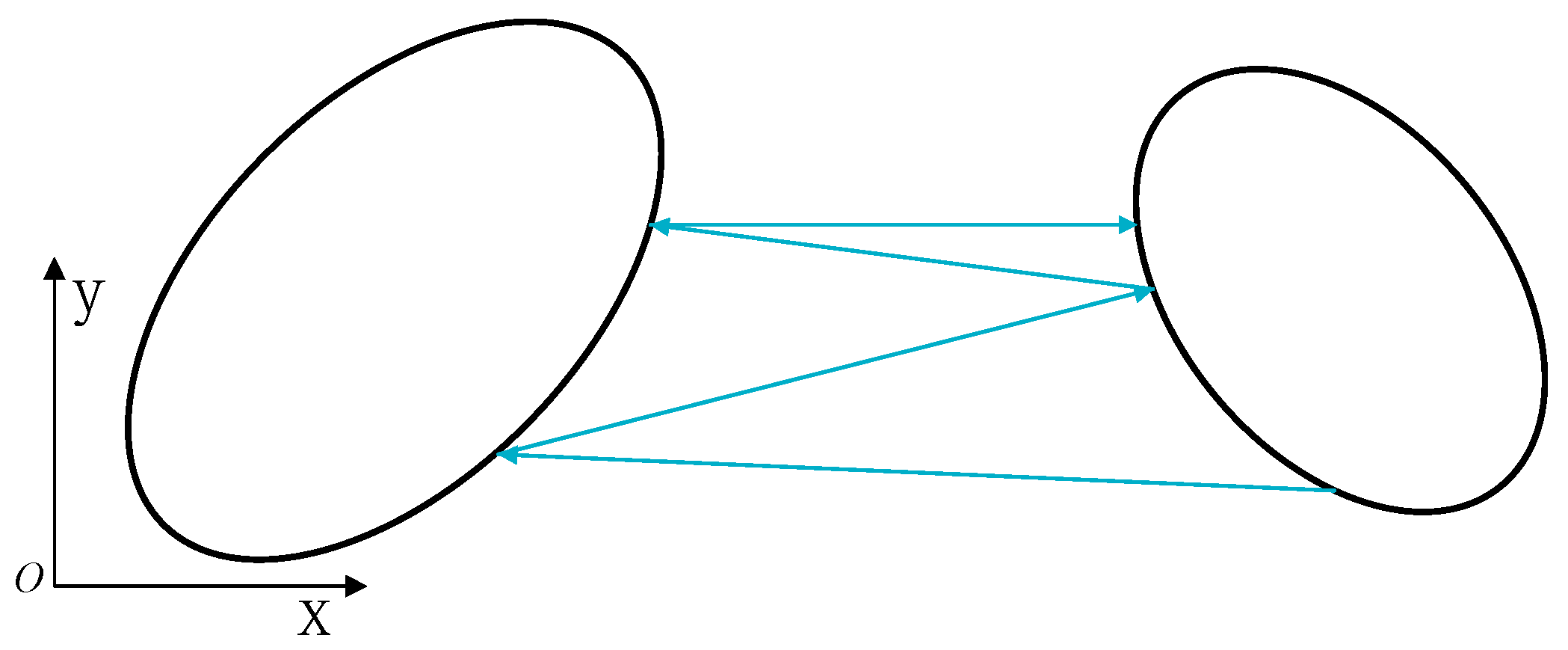
Figure 2.
Process of the iteration to calculate the distance between two ellipses on a plane.

Figure 3.
Simulation results of model with 100 identical circular particles under uniaxial compress loading. (A) Nominal stress–strain relations of bulk metallic glass composite (BMGC) and bulk metallic glass (BMG). (B) (a–d) equivalent plastic strain distributions in BMG corresponding to the positions (I–IV).

Figure 4.
The influence of particle orientation on the stress-strain curves of MGMCs (metallic glass matrix composites).
Figure 4.
The influence of particle orientation on the stress-strain curves of MGMCs (metallic glass matrix composites).

Figure 5.
The influence of particle orientations on normalized free volume in BMG. (a) α = 0°; (b) α = 22.5°; (c) α = 45°.
Figure 5.
The influence of particle orientations on normalized free volume in BMG. (a) α = 0°; (b) α = 22.5°; (c) α = 45°.

Figure 6.
The influence of particle shape on the stress–strain curves of metallic glass matrix composites (MGMCs).
Figure 6.
The influence of particle shape on the stress–strain curves of metallic glass matrix composites (MGMCs).

Figure 7.
The influence of particle shapes on normalized free volume in BMG: (a) ; (b) and (c) .

Figure 8.
The influence of particle volume fractions on the stress–strain curves of MGMCs.

Figure 9.
The influence of particle volume fractions on normalized free volume in BMG. (a) Vf = 15%; (b) Vf = 25%; (c) Vf = 35%.
Figure 9.
The influence of particle volume fractions on normalized free volume in BMG. (a) Vf = 15%; (b) Vf = 25%; (c) Vf = 35%.

Figure 10.
The influence of particle shape on the stress–strain curves of MGMCs.

Figure 11.
The influence of load conditions on the normalized free volume in BMG.

© 2018 by the authors. Licensee MDPI, Basel, Switzerland. This article is an open access article distributed under the terms and conditions of the Creative Commons Attribution (CC BY) license (http://creativecommons.org/licenses/by/4.0/).
Share and Cite
MDPI and ACS Style
Bian, P.-L.; Liu, T.-L.; Qing, H.; Gao, C.-F. 2D Micromechanical Modeling and Simulation of Ta-Particles Reinforced Bulk Metallic Glass Matrix Composite. Appl. Sci. 2018, 8, 2192. https://doi.org/10.3390/app8112192
AMA Style
Bian P-L, Liu T-L, Qing H, Gao C-F. 2D Micromechanical Modeling and Simulation of Ta-Particles Reinforced Bulk Metallic Glass Matrix Composite. Applied Sciences. 2018; 8(11):2192. https://doi.org/10.3390/app8112192
Chicago/Turabian StyleBian, Pei-Liang, Tian-Liang Liu, Hai Qing, and Cun-Fa Gao. 2018. "2D Micromechanical Modeling and Simulation of Ta-Particles Reinforced Bulk Metallic Glass Matrix Composite" Applied Sciences 8, no. 11: 2192. https://doi.org/10.3390/app8112192
Note that from the first issue of 2016, this journal uses article numbers instead of page numbers. See further details here.