Article

Feasibility Study of Wind Farm Grid-Connected Project in Algeria under Grid Fault Conditions Using D-Facts Devices

by
Lina Wang
1,
Kamel Djamel Eddine Kerrouche
1,5,*,
Abdelkader Mezouar
2,
Alex Van Den Bossche
3,
Azzedine Draou
4 and
Larbi Boumediene
2
1
School of Automation on Science and Electrical Engineering, Beihang University, Beijing 100191, China
2
Electro-Technical Engineering Lab, Faculty of Technology, Tahar Moulay University, Saida 20 000, Algeria
3
Electrical Energy LAB EELAB Sint–Pietersnieuwstraat 41, B 9000 Ghent, Belgium
4
Department of Electrical Engineering, Madinah Mounawara University, Madinah 20012, Saudi Arabia
5
Satellite Development Center CDS, BP 4065 Ibn Rochd USTO, 31000 Oran, Algeria
*
Author to whom correspondence should be addressed.
Appl. Sci. 2018, 8(11), 2250; https://doi.org/10.3390/app8112250
Submission received: 21 October 2018 / Revised: 5 November 2018 / Accepted: 8 November 2018 / Published: 15 November 2018
(This article belongs to the Special Issue Large Grid-Connected Wind Turbines)

Abstract

:
The use of renewable energy such as wind power is one of the most affordable solutions to meet the basic demand for electricity because it is the cleanest and most efficient resource. In Algeria, the highland region has considerable wind potential. However, the electrical power system located is this region is generally not powerful enough to solve the problems of voltage instability during grid fault conditions. These problems can make the connection with the eventual installation of a wind farm very difficult and inefficient. Therefore, a wind farm project in this region may require dynamic compensation devices, such as a distributed-flexible AC transmission system (D-FACTS) to improve its fault ride through (FRT) capability. This paper investigates the implementation of shunt D-FACTS, under grid fault conditions, considering the grid requirements over FRT performance and the voltage stability issue for a wind farm connected to the distribution network in the Algerian highland region. Two types of D-FACTSs considered in this paper are the distribution static VAr compensator (D-SVC) and the distribution static synchronous compensator (D-STATCOM). Some simulation results show a comparative study between the D-SVC and D-STATCOM devices connected at the point of common coupling (PCC) to support a wind farm based on a doubly fed induction generator (DFIG) under grid fault conditions. Finally, an appropriate solution to this problem is presented by sizing and giving the suitable choice of D-FACTS, while offering a feasibility study of this wind farm project by economic analysis.

Graphical Abstract

1. Introduction

In Algeria, the first attempt to connect the wind energy conversion system (WECS) to the electricity distribution network dates back to 1957, with the installation of a 100-kW wind turbine at the Grands Vents site (Algiers) by the French designer Andreau.
Nowadays, the depletion of fossil fuels reserves in Algeria, fluctuations in oil price and the location of energy resources are causing instability in energy policy.
In addition, the use of fossil fuels for conventional power plants triggers alarms of an environmental disaster. Currently, to reduce the harmful impact of conventional resources and improve Algerian energy efficiency, the energy policy program announced by the Ministry of Mines and Energy aims, by 2030, to produce 40% electrical energy from renewable resources [1]. For WECS, the power to be produced over the period 2012–2022 is estimated at approximately 516 MW, of which 10 MW are installed at Kabertene (70 km from Adrar) in the Algerian desert [1,2,3,4]. This pilot wind farm consists of 12 wind turbines with a unit capacity of 0.85 MW, the energy produced will be injected to the 30/220 kV step up transformer situated in the same locality [1], as shown in Figure 1. Currently, the Algerian electrical grid code does not consider WECS. In the region of Adrar, the electrical grid is not interconnected with the north; it is a local grid (or micro-grid). Therefore, this program of the energy policy must be accompanied by continual development of wind energy technology and optimization techniques, looking for better options concerning reduced costs, improvement regarding wind turbine performances, reliability of electrical groups and electrical grid integration.
In the period of 2009–2010, Sebaa Ben Miloud F et al. [6] and Himri et al. [7] undertook the first study to identify a suitable site in Adrar region for the wind farm installation. In addition, Himri et al. [7] used data of wind speed over a period of nearly 10 years to assess the potential of wind power stations in two southern Algerian regions, namely, Timimoun and Tindouf. In [8], a study of the wind potential in seven southern Algerian sites was undertaken, from west to east, Tindouf, Bechar, Adrar, and Ghardaia, In Amenas and In Salah (Tamanrasset). In [9] wind speed data was collected over a period of almost 5 years, from three selected stations in northern Algeria. Within this context, some studies in the Algerian high plateau region were performed in [10,11,12]. However, the authors did not consider the integration issue of the wind farm into the electrical grid and it is well known that the electrical grid influences greatly the performance of wind farm installation and production.
At the present time, doubly fed induction generators (DFIG) are the most used in WECS [13,14] and especially in the Algerian wind farm at Kabertene in Adrar. Simple induction generators have some weaknesses such as reactive power absorption and uncontrolled voltage during variable rotor speed. These complications are avoided by the installation of DFIG and power converters or power drives [15,16]. The particular feature of the DFIG is that the injected power by the rotor converter is only a small part from the total provided power with its stator directly connected to the electrical grid [17,18,19]. Hence, the size, the cost and losses of the power converter are optimized compared to a full-size power converter of the other generators.
One of the most important considerations in a wind farm grid-connected project is fault ride-through (FRT) capability, where the energy grid is often weak and the DFIG is frequently working under grid faults when the wind farm is located relatively far from this electrical grid [20]. Therefore, many research works focus on studying the dynamic behaviors of wind farms during and after the clearance of the grid fault conditions without disconnection from the electrical grid. In [21], several methods employed to improve the FRT capability of the fixed-speed wind turbines are based on induction generators. In [20], an enhanced application to overcome grid fault conditions is studied for a wind farm based on DFIG. FRT control of wind turbines with DFIGs under symmetrical voltage dips is presented in [21]. In [22] a flexible AC transmission system (FACTS) system for DFIG to reduce the effects of grid faults is proposed.
The present paper can extend the aforementioned research works. This paper, shows the feasibility of installing a wind farm in an Algerian highland region, confirmed by some data of wind potential in the selected geographical location in the first part, which is an input for the wind power system. On the other hand, another important aspect is the weakness of the electrical grid, which is often an obstacle in many countries that have established wind energy projects. Consequently, during the feasibility study, some techniques to identify the cost-effectiveness of areas for the wind farms installations, the possible electrical path of distribution lines, and their corresponding estimated cost are used, and the incorporation of electrical devices such as distributed FACTS (D-FACTS) technology is considered. Furthermore, the investors may be confident to fund this possible project when these technical difficulties are taken into consideration. Then, in order to ensure the economic success of the future wind farm project in the highland region, an accurate study by some simulation results, showing the interaction between wind turbine generators and the electrical grid in this region with the impact of the D-FACTS systems, is undertaken, which has not been previously done. In this study, the Algerian electrical grid code could be considered in simulations similar to that of the Spanish grid code as shown in Figure 2.

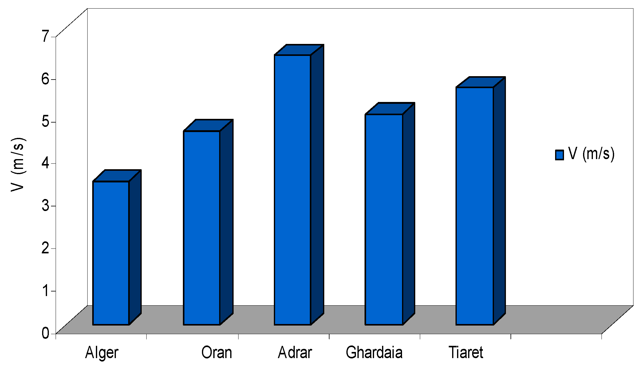
2. Algerian Wind Potential

This section discusses a method for determining the production of wind energy at different sites in Algeria in order to choose a suitable site for a cost-effective energy installation. Thus, we have both the average wind speed and the power produced by wind turbines; we can combine them to calculate the energy produced by these wind turbines. Furthermore, in this paper, five selected geographical locations (altitude, latitude and longitude) shown in Table 1 and Figure 3 were obtained from the National Meteorological Office (NMO) [24].
These wind speed data are collected only at 10 m of altitude, measured using a type of anemometer cup and vane. However, the action of the wind speed at the turbine (tower height over 70 m) is very complex, and includes both deterministic effects (wind and shadow average round), and stochastic fast varying wind speed is turbulent. In fact, wind speed describing these variations is usually measured in the lower atmosphere using either instrumented towers or tethered balloons, which have not been available in previous stations [25,26].
The wind speed is the most important aspect of wind potential; in fact, the annual variation of the long-term average wind speed provides a good understanding of the long-term trend of wind speed and gives confidence to investors on the availability of wind energy in the years ahead [27]. Figure 4 provides the average wind speed during five years of data collection at 5 stations in Algeria, which are considered in this study [7,10,11,12,13,14,15,16,17,18,19,20,21,22,23,24,25,26,27,28,29,30,31,32,33,34].

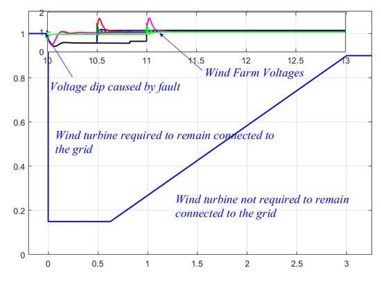
3. Connection Issue of a Wind Farm to the Electrical Grid

In this paper, the proposed wind farm in a highland region with average power is considered as a decentralized generator unit, which is most often connected to the distribution network and that differs from centralized generator units. In Algeria, the electrical distribution grids are the most important infrastructure of the whole power system, which is considered as the final interface that leads to most industrial and domestic customers. These distribution grids are operated in ranges of voltages below 50 kV, which is the voltage level of the Medium Voltage (MV) and Low Voltage (LV) ranges. Moreover, in the Algerian distribution grid, the nominal voltage of the MV is 10 kV and 30 kV. These voltage levels allow a good compromise to limit the voltage drops, minimizing the number of source positions (connecting to High Voltage (HV)/MV power station) and reduce the inherent constraints to high voltages (investment costs, protection of property and persons). Moreover, Algerian distribution grids are, in most cases, radially networked. The map of the western Algerian electrical grid is shown in Figure 5. This figure shows the structure of the High Voltage B 220 kV transmission lines, while the substations and power plants are also shown in this figure [1]. The structure of High Voltage A 60 kV distribution lines is shown in Figure 6.
Based on the structure of the electrical grid on the west side near the proposed wind farm (see Figure 6), this radial electrical grid of 60 kV can be reconfigured; it is then simulated using the Power System Analysis Toolbox (PSAT) software with actual electrical grid parameters and consumer profiles at the peak load of each bus, with a centralized generation source Tiaret City (TIARC) power plant. Simulation of the latter gives the results shown in Figure 7 and Figure 8. More details on the overall simulation of the west Algerian grid can be found in [34].
The existence of an SNVI industrial site in the bus of N 2 between the city of Tiaret and the city of Tissemsilt can justify the presence of the voltage drop across this line as shown in Figure 7a. This resulted in demand of an excessive reactive power and active line losses due to the high-fluctuated demand of energy to the industrial site, as shown in Figure 7b and Figure 8.

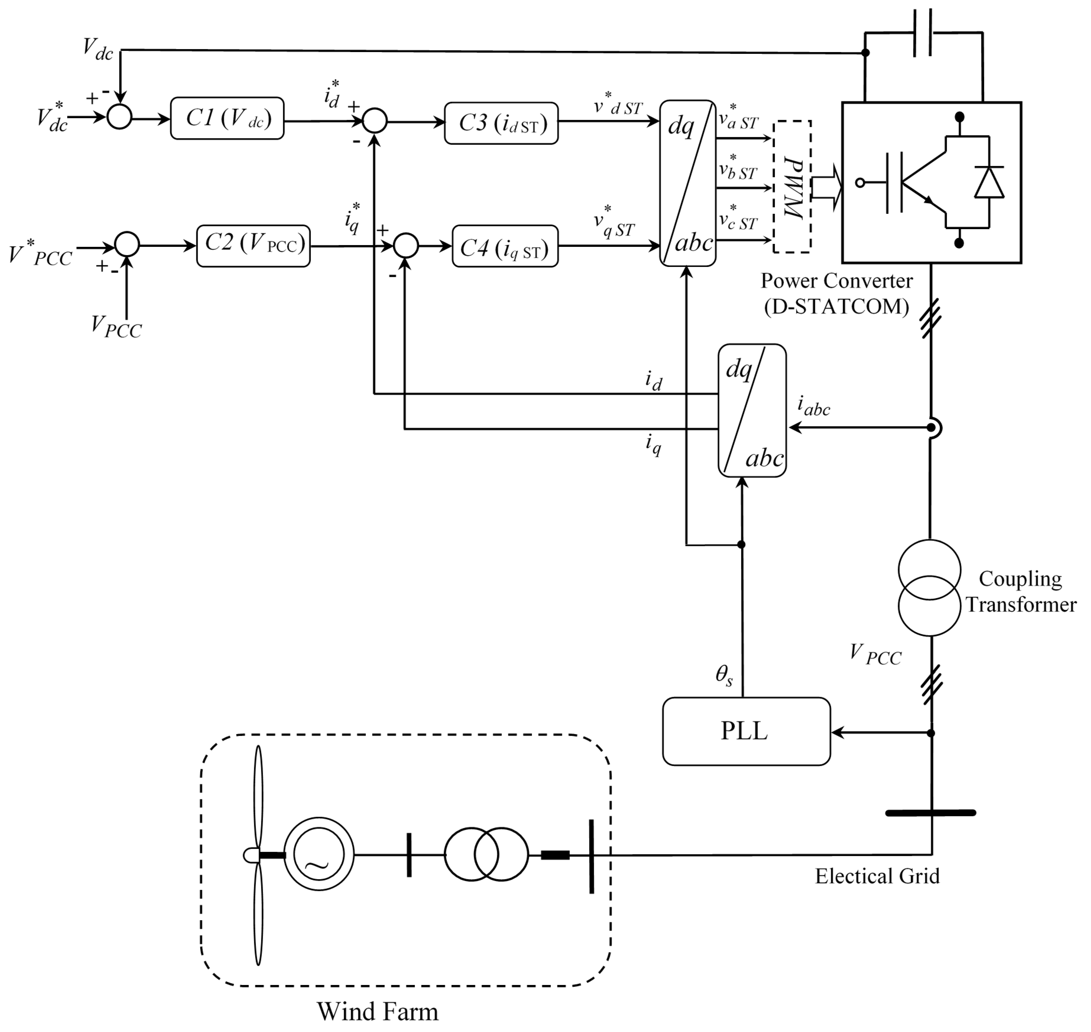
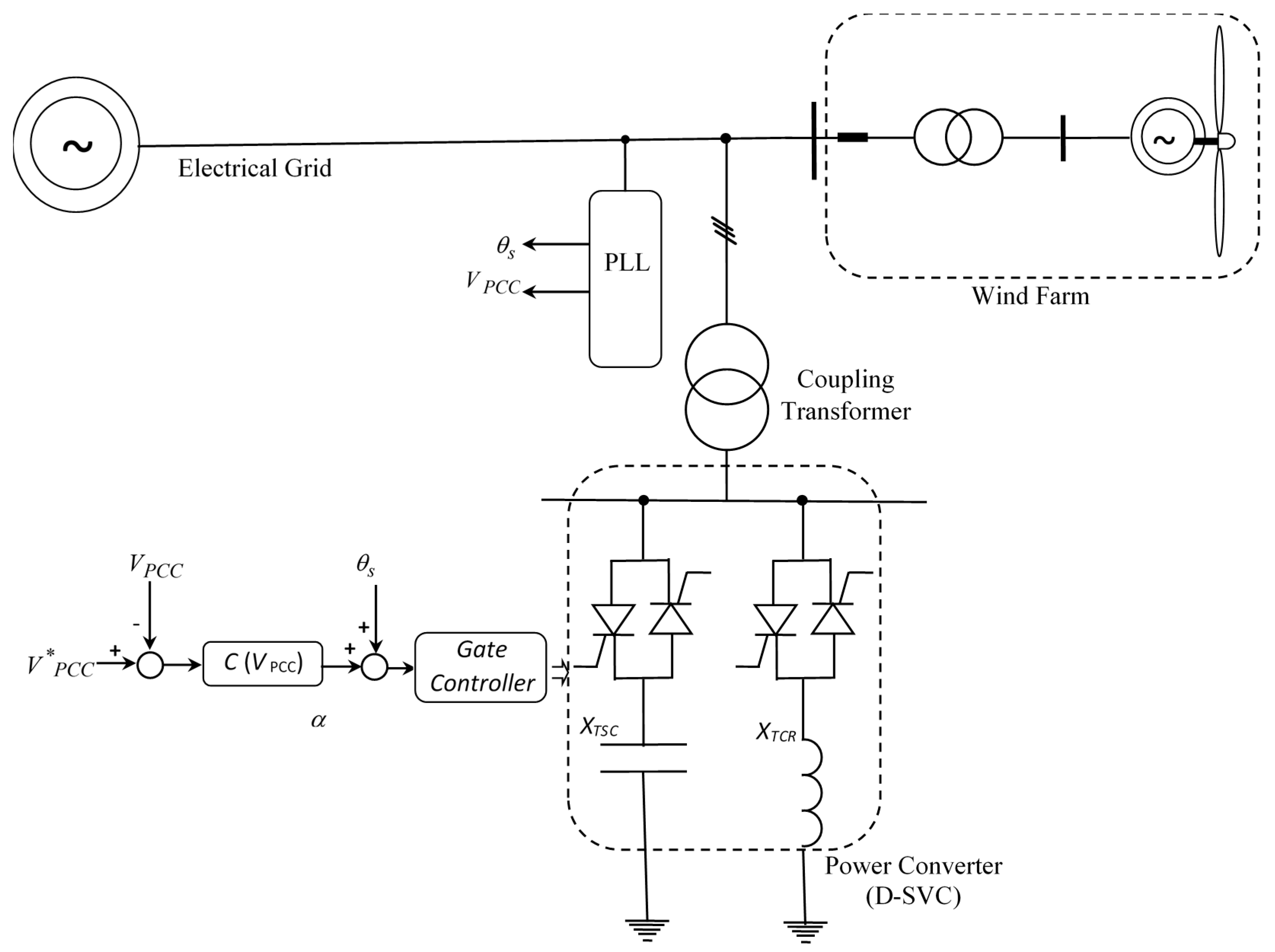
4. Distribution Flexible Alternative Current Transmission System (D-FACTS)

Shunt D-FACTS devices can be classified into two main categories, namely the variable impedance type such as the distribution static var compensator (D-SVC) and the switching converter type such as the distribution static synchronous compensator (D-STATCOM).
The configuration of the D-SVC connected to the distribution grid is shown in Figure 9.
This figure shows a D-SVC consisting of a thyristor switched capacitor (TSC) part composed by two switching thyristors connected with capacitive reactance XTSC; the other part is the thyristor-controlled reactor (TCR) composed by two thyristors connected with an impedance of an inductive reactance branch XTCR. By controlling the angle thyristors (the angle with respect to the zero crossing of the phase voltage), the device is able to control the amplitude of the voltage at the point of common coupling (PCC) due to the changes in the angle resulting mainly in changes of the current. Therefore, the amount of the reactive power consumed by the inductor L, for an angle of α = 90°, the inductive circuit is activated, whereas for α = 180°, this inductive circuit is off.
The configuration of the D-STATCOM connected to the distribution grid is shown in Figure 10.
This figure shows the different blocks constituting this configuration of the control strategy, which consists of: A phase lock loop (PLL) for synchronization of the component of the positive sequence voltage with the primary voltage of the power distribution grid. An external control loop consists of controlling the DC bus voltage and the grid voltage. The outputs of the voltage controllers are the current references for the current controllers. The internal current control loop consists of the current controllers. The outputs of the current controllers consist in imposing the amplitude and phase of voltages of the D-STATCOM by generating Pulse Width Modulation (PWM) signals.

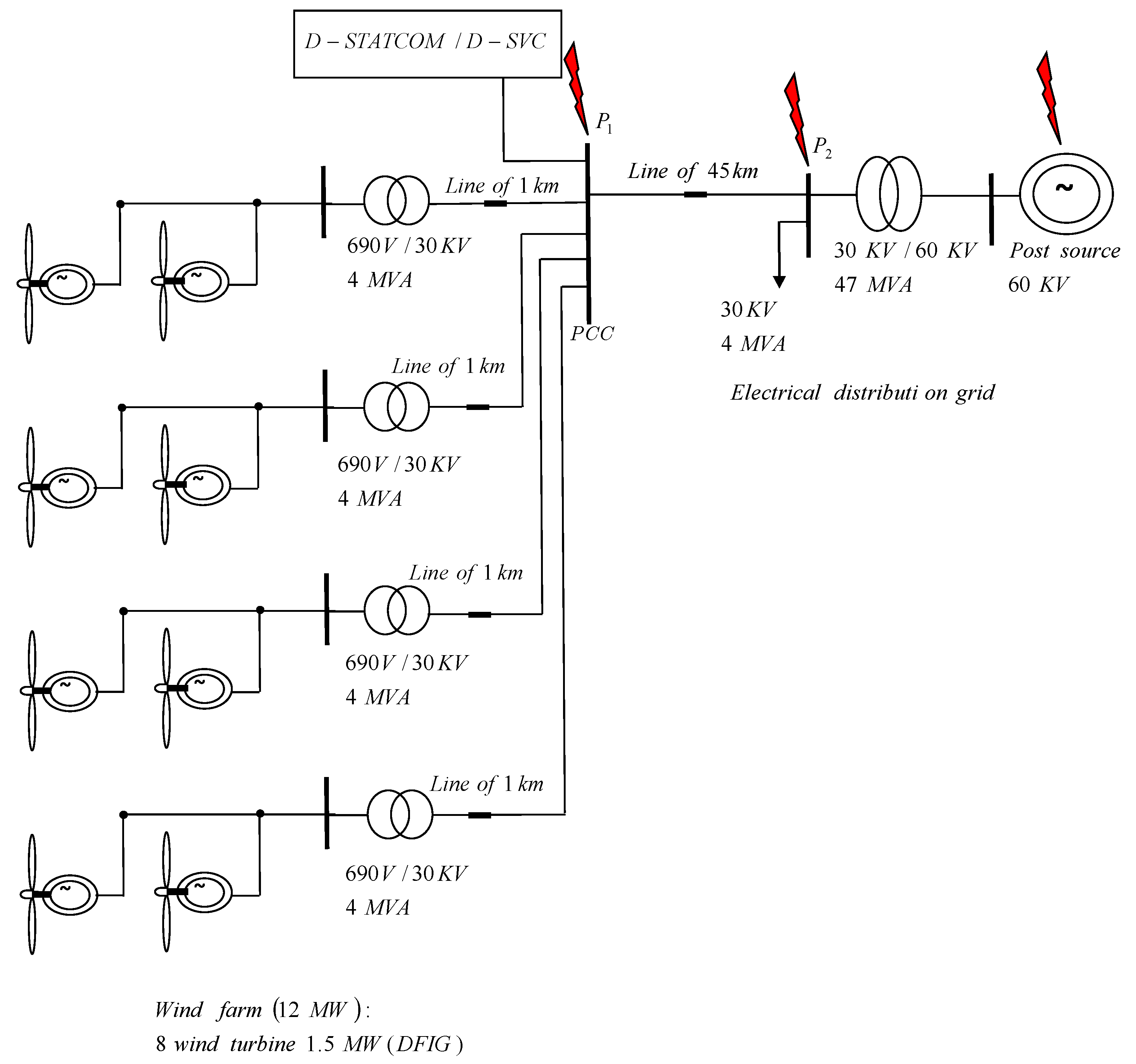
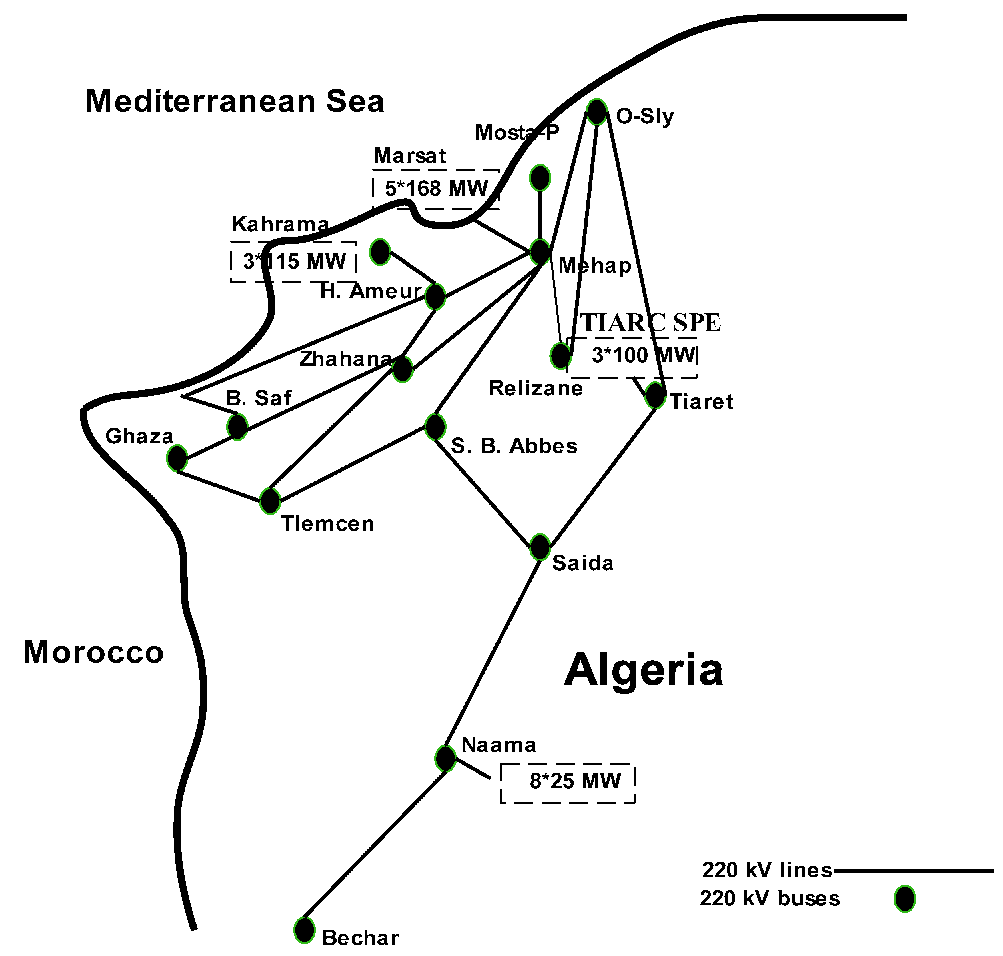
5. Constitution of the Wind Farm and the Location of the Shunt D-FACTS

The wind farm connected to the distribution system proposed in this section is shown in Figure 11, which consists of eight DFIGs with 1.5 MW of power for each wind turbine. These generators are connected between them to a voltage level of 30 kV by a step-up transformer 690 V/30 kV with 4 MVA of power for each generator. Then a 45 km line that is connected to the source substation 60 kV through another step-up transformer 30 kV/60 kV with 47 MVA of power. For this study, these lines are modelled with the π model.
Based on the work done in [21,35] the simulation results obtained with a D-FACTS provides an effective support to the bus voltage to which it is connected. Therefore, in this study, D-FACTS is placed at the PCC for two reasons:
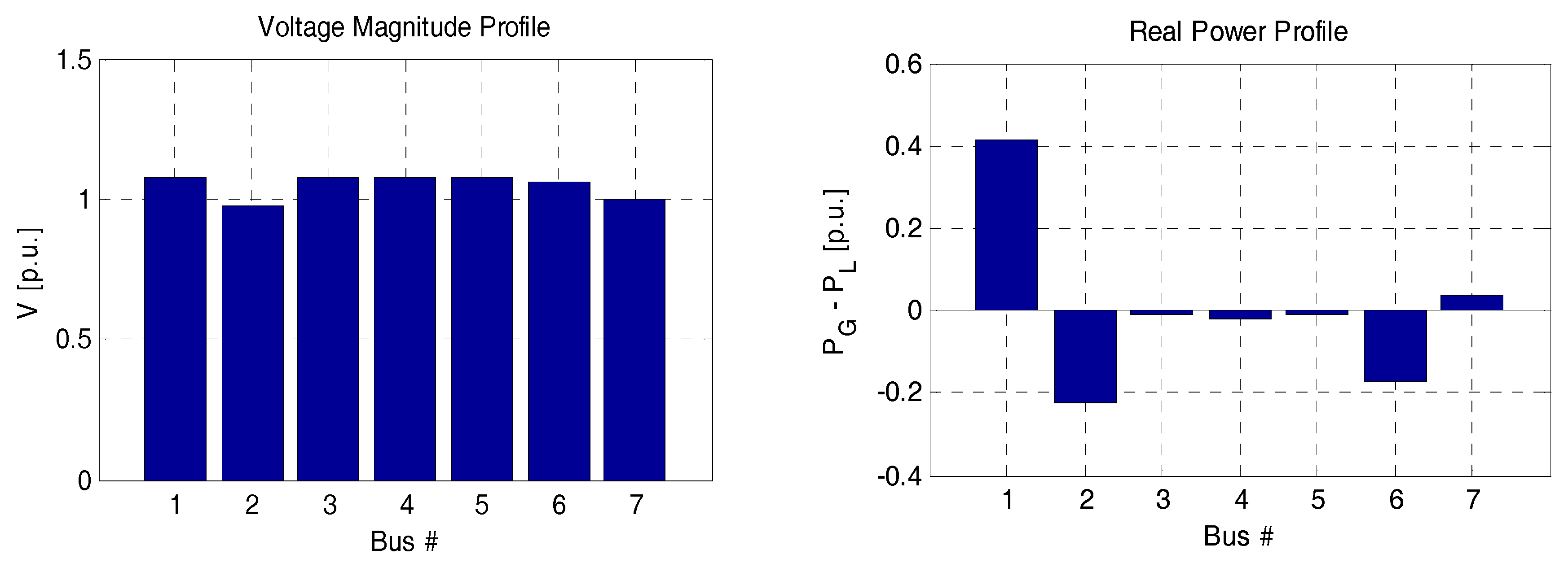
  • The location for the reactive power support should be as close as possible to the point at which the carrier is necessary because of the variation in the voltage and, therefore, power loss (Joule loss) in the distribution line associated with reactive power flow,
  • In the studied system, the effect of the change in voltage is most common in this bus.

6. Simulation Results

In this section, simulations are performed on Matlab/Simulink, to show the impact of D-FACTS on the ability to control the voltage at the PCC between the electric distribution grid and the wind farm, which is described in the previous section (Figure 11). According to the previous section of the wind potential in the Algerian highland region, the considered wind speed in the simulation starts at 8 m/s and then reaches 9 m/s. The parameters of generators and D-FACTS are presented in the Appendix A.
For the more detailed study, the proposed system devices, the D-SVC and D-STATCOM structures used in the context of this paper are the same as the SVC and STATCOM structures, which are presented in [36,37], giving their associated models with their appropriate control schemes. In addition, the detailed model with some simulations for WECS based on DFIG in power system dynamics are described in [38,39,40,41]. Generally, a short-circuit fault has a significant effect on the wind farm; a voltage drop is caused even if the fault is located near or far from the PCC or the wind farm. This voltage drop at the PCC leads to an over-current in the rotor circuit of DFIG, and fluctuations in the DC bus voltage. Therefore, the rotor side converter (RSC) of the DFIG should be blocked to avoid being damaged by overcurrent in the rotor circuit.
The block diagram of the simulated wind farm connected to the electrical distribution grid is shown in Figure 12.
In order to study the behavior and the impact of electrical faults in the distribution grid on the wind farm, worst-case scenarios of grid faults were assumed and included in the simulation. Therefore, the entire system was tested under two types of grid faults:
  • Line to line electrical grid fault.
  • Voltage drop at the 60 kV bus.
The wind speed is considered as constant during the grid fault period, except for this disturbance; and generators and the electrical distribution grid are considered to be working in ideal conditions (no disturbances and no parameter variations in the studied system).

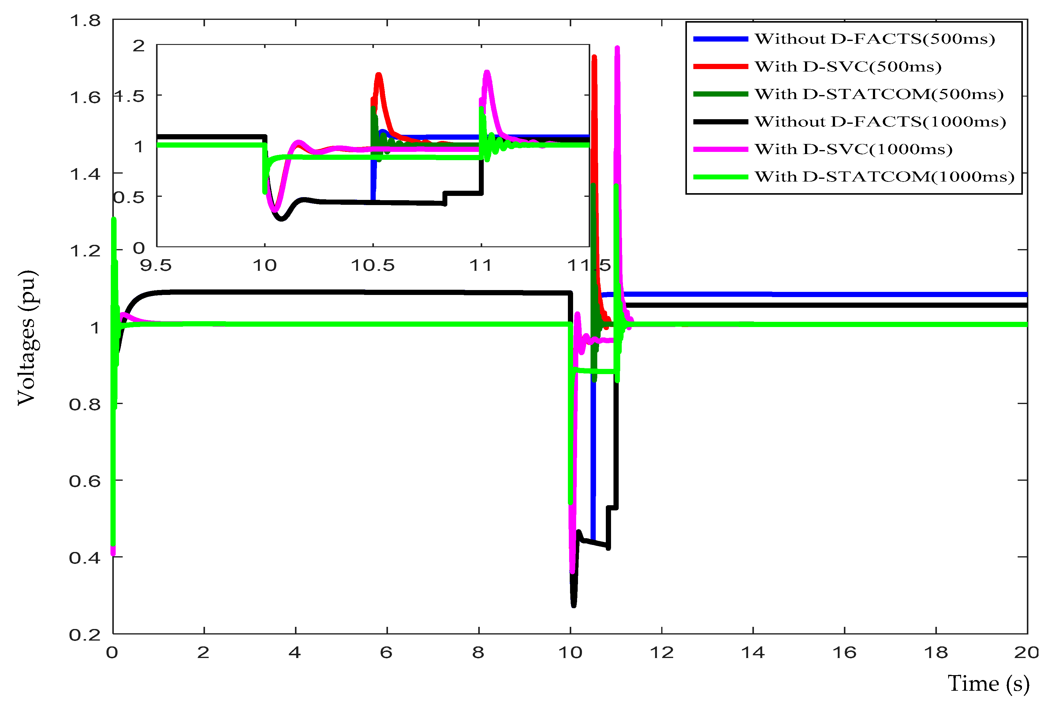
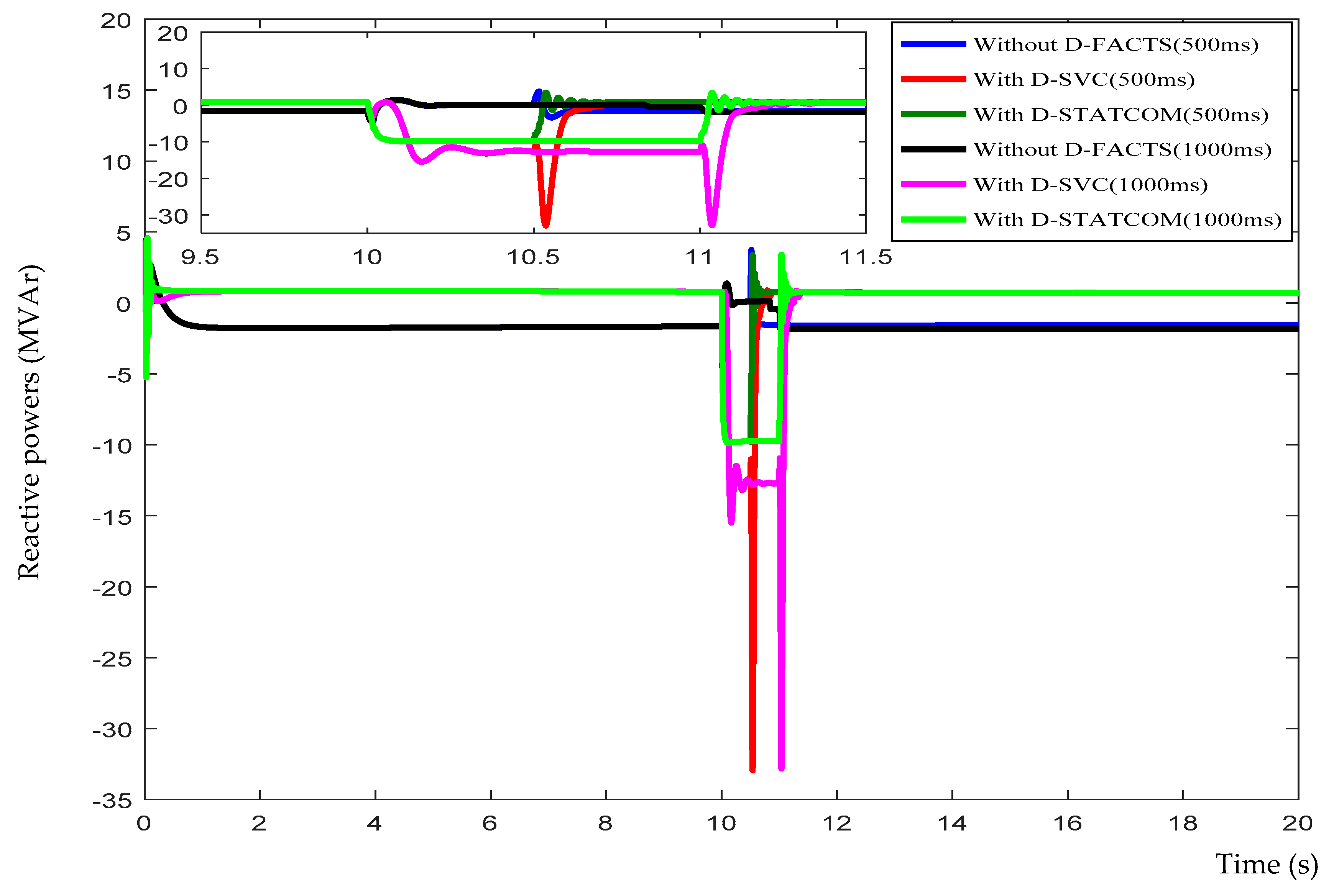
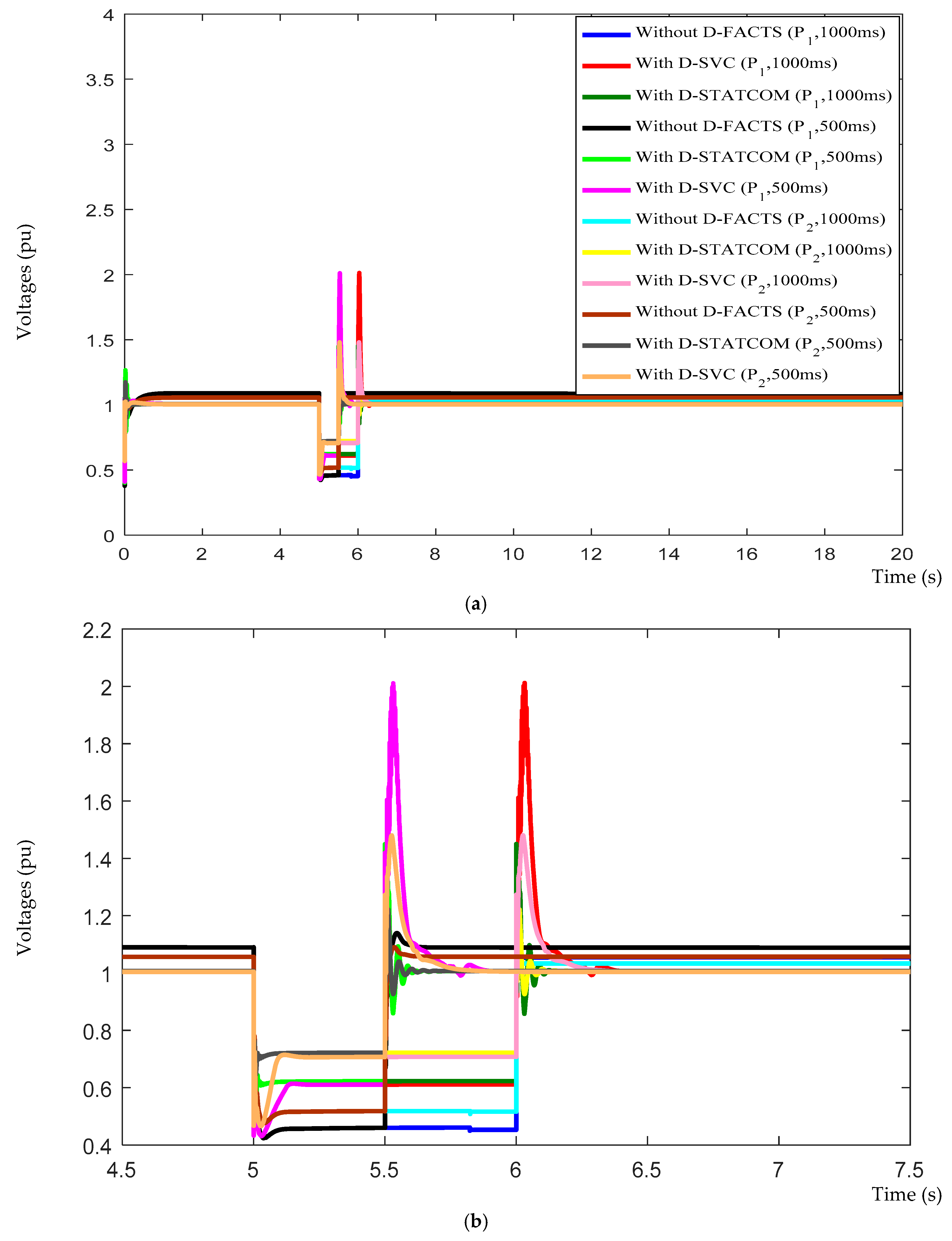
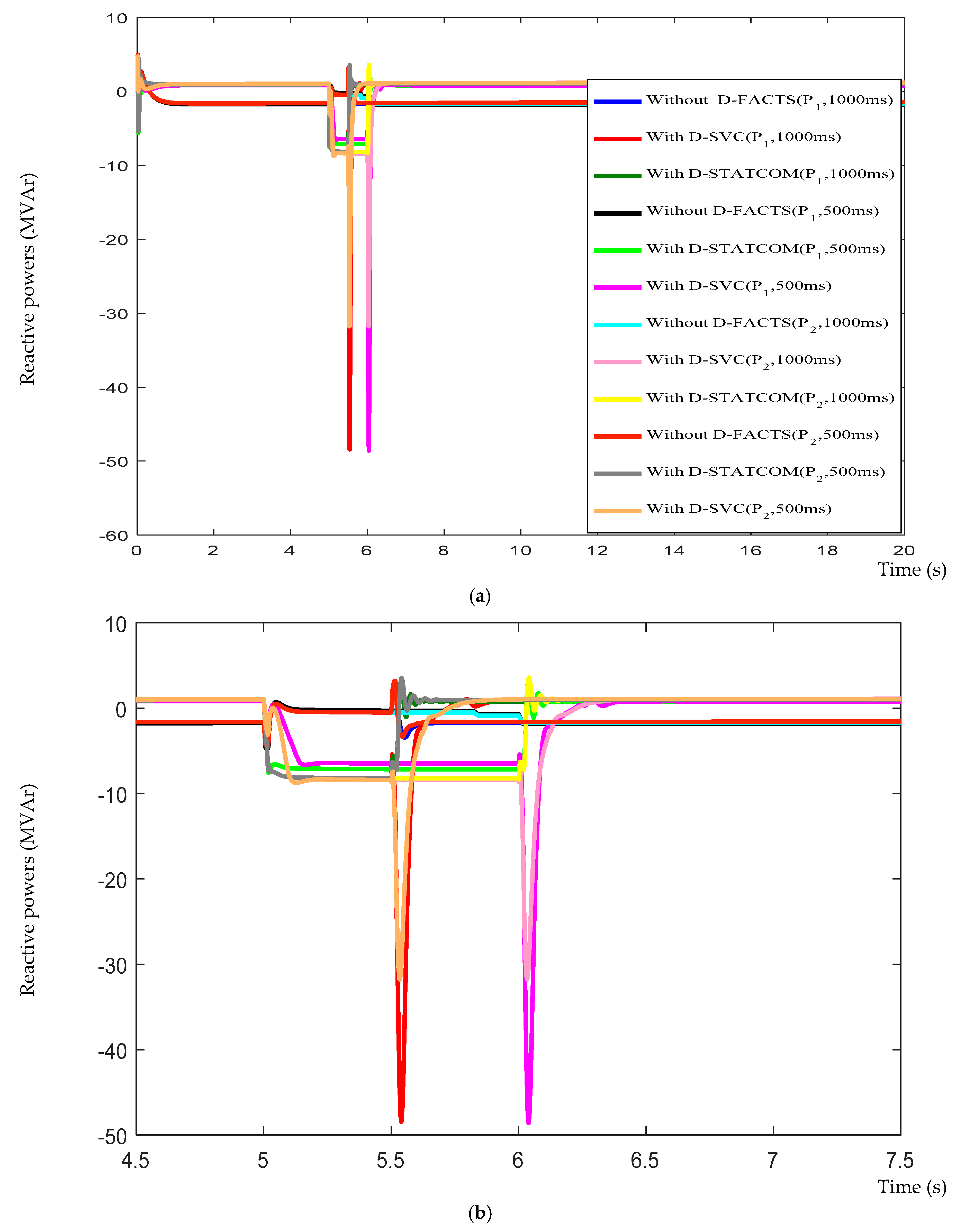
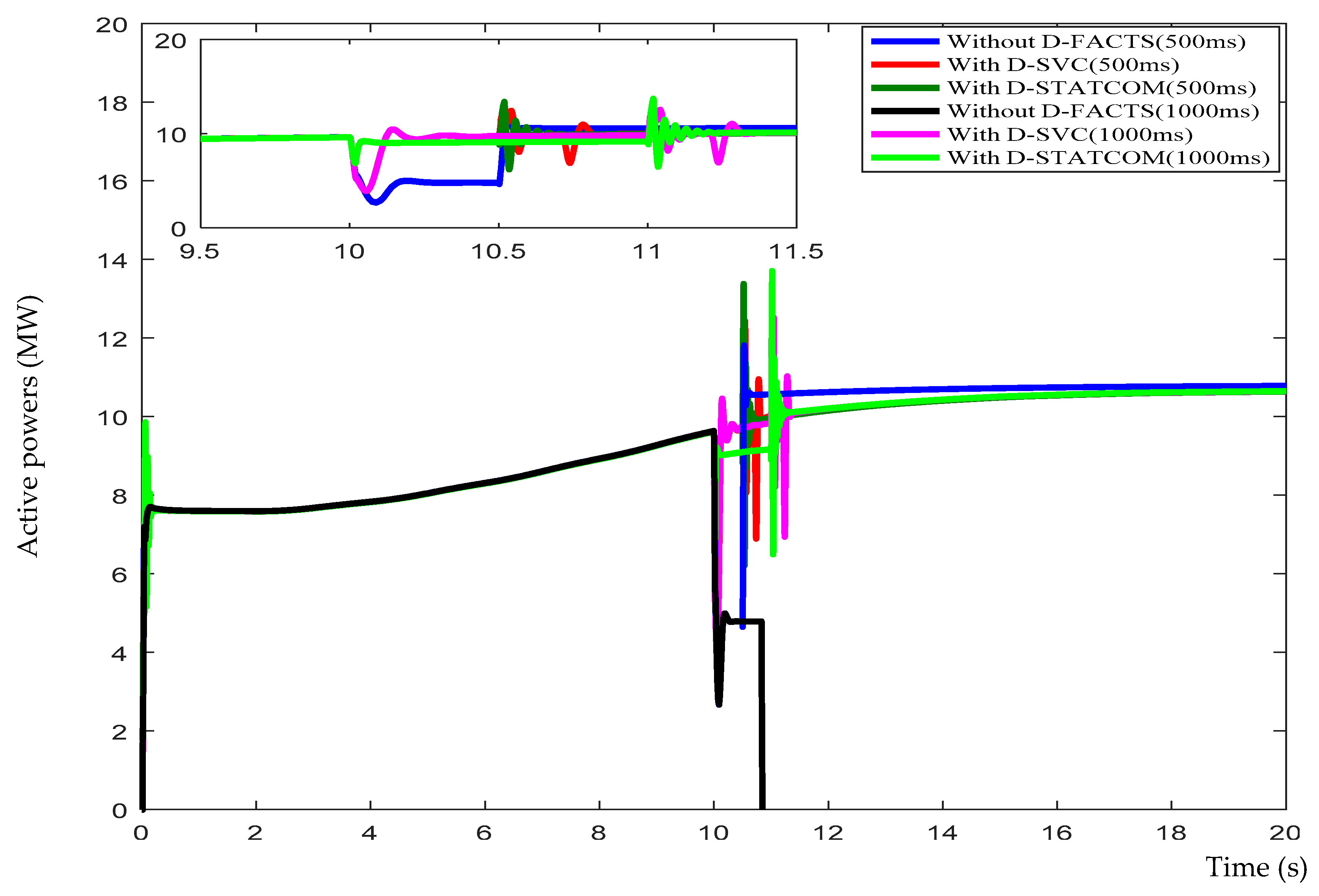
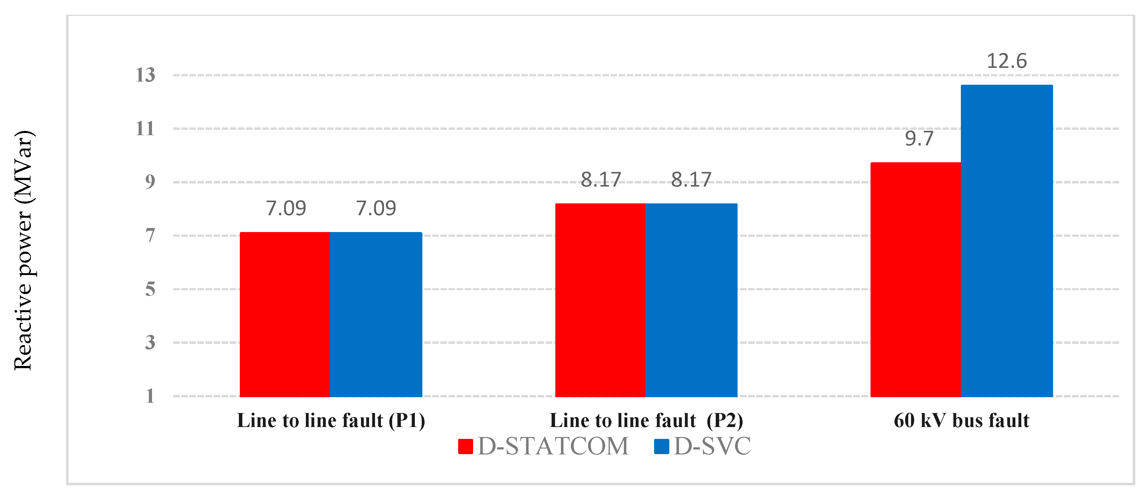
6.1. Simulation Results of the Line-to-Line Electrical Grid Fault

In this section, we consider that the phases “b” and “c” at the PCC at P1 come into accidental contact. Then, the same grid fault is considered at a distance of 45 km from the PCC to the point P2 (Figure 11). Simulation results for this grid fault are shown in Figure 13, Figure 14 and Figure 15.
The active powers at the PCC with a short temporary grid fault of two-phase to ground are shown in Figure 14. The reactive powers at the PCC with a short temporary grid fault of two-phase to ground are shown in Figure 15.
According to Figure 13, which reveals that without the use of D-FACTS systems the voltage at the PCC exceeds the acceptable voltage level 1 pu due to the voltage swell. However, using D-FACTS devices such as D-SVC and the D-STATCOM these undesirable effects are corrected. In addition, voltages at the PCC during a temporary grid fault presented in this figure show that, without the use of D-FACTS and when the grid fault is at the point P1, the voltage at the PCC drops to the value of 0.48 pu, which is less than the acceptable value. Thus, when the grid fault is at the point P2 without D-FACTS, the voltage drops to 0.52 pu. However, with the presence of D-FACTS devices, when this type of grid fault is at point P1, the voltage at the PCC drops to 0.63 with a slight fluctuation. In addition, when the fault is at the point P2 with D-FACTS, the voltage is maintained at 0.71 pu. Moreover, it is noticed that the voltage at the PCC, when using D-STATCOM many oscillations are mitigated compared to using the D-SVC.
According to Figure 14, which shows that during the occurrence of the same grid fault type in both points P1, P2 and without the presence of D-FACTS systems, no active power is supplied. Then, when the grid fault of 1000 ms duration exceeds the limit (see Figure 2), the wind farm is disconnected from the grid. Moreover, the installation of D-FACTS systems at the PCC guarantees the wind farm commissioning during and after this type of grid fault at these points (P1, P2) without disconnecting from the electrical distribution grid, providing the active power of 10.6 MW. Therefore, in the presence of D-FACTS systems, production of active power by the wind farm is uninterrupted and in the absence of these systems the wind farm is disconnected from the grid by triggering the protection system.
From Figure 15, it is noticed that in the absence of D-FACTS systems and when the grid fault is located at the points P1 and P2, no exchange of reactive power is provided to the electrical distribution grid. However, in the presence of D-FACTS systems, it provides almost the same amount of reactive power, 7.09 MVAr, when the grid fault is located at point P1 and 8.17 MVAr when the grid fault is located at point P2. Indeed, these injected reactive powers are required for compensation to maintain the stability of the wind farm with the voltage at the PCC around the acceptable value. Therefore, the wind farm is kept in service during and after this type of grid fault without disconnecting from the electrical distribution grid. Thus, the use of D-STATCOM has a capacity to compensate faster than using the D-SVC and the peaks of the injected reactive powers are eliminated.

6.2. Simulation Results of the Voltage Drop at the 60 kV Bus

The main purpose of this test is to study how a remote grid fault from the PCC may affect the operation of a wind farm; this fault affects the source of 60 kV, which is far from the PCC where the wind farm based on the DFIGs is connected to the grid. Hence, a temporary voltage drop of 50% is applied to the source for the duration of 500 ms at t = 10 s, and then the same grid fault for 1000 ms of duration.
Figure 16 shows that during this type of grid fault and without the presence of D-FACTS, the voltage at the PCC drops to 0.44. Therefore, the protection system will be triggered and the wind farm will be disconnected if the fault duration exceeds the electrical interconnection grid code for the wind turbine systems (see Figure 2). However, in the same figure, it is shown that during this grid fault and with the presence of D-FACTS systems, the voltage at the PCC is maintained around 0.88 pu with a transient peak without triggering the protection system. Thus, by using the D-STATCOM, transient peaks are reduced and the time response is faster than by using the D-SVC.
The active powers at the PCC are presented in Figure 17.
Figure 17 shows that, when the D-FACTS devices are not installed at the PCC, the wind farm cannot maintain its connection to the grid during the grid fault that lasts 1000 ms because the protection systems are triggered and the wind farm is disconnected. However, after the installation of D-FACTS devices and with the same grid fault type and the same duration of grid fault, the wind farm can return to the steady state and inject the active power of 10.6 MW to the grid.
From the results shown in Figure 18, it is noticed that without the presence of a compensation system, the wind farm is operating in a weak electrical grid due to its normal behavior and there is no reactive power exchange with the electrical grid. However, in the same situation with the D-FACTS devices, the necessary reactive power is provided to the grid of 12.6 MVAr with D-SVC and 9.7 MVAr with the D-STATCOM. Thus, a very fast and significant fluctuation is observed with the use of the D-SVC compared to the use of the D-STATCOM.

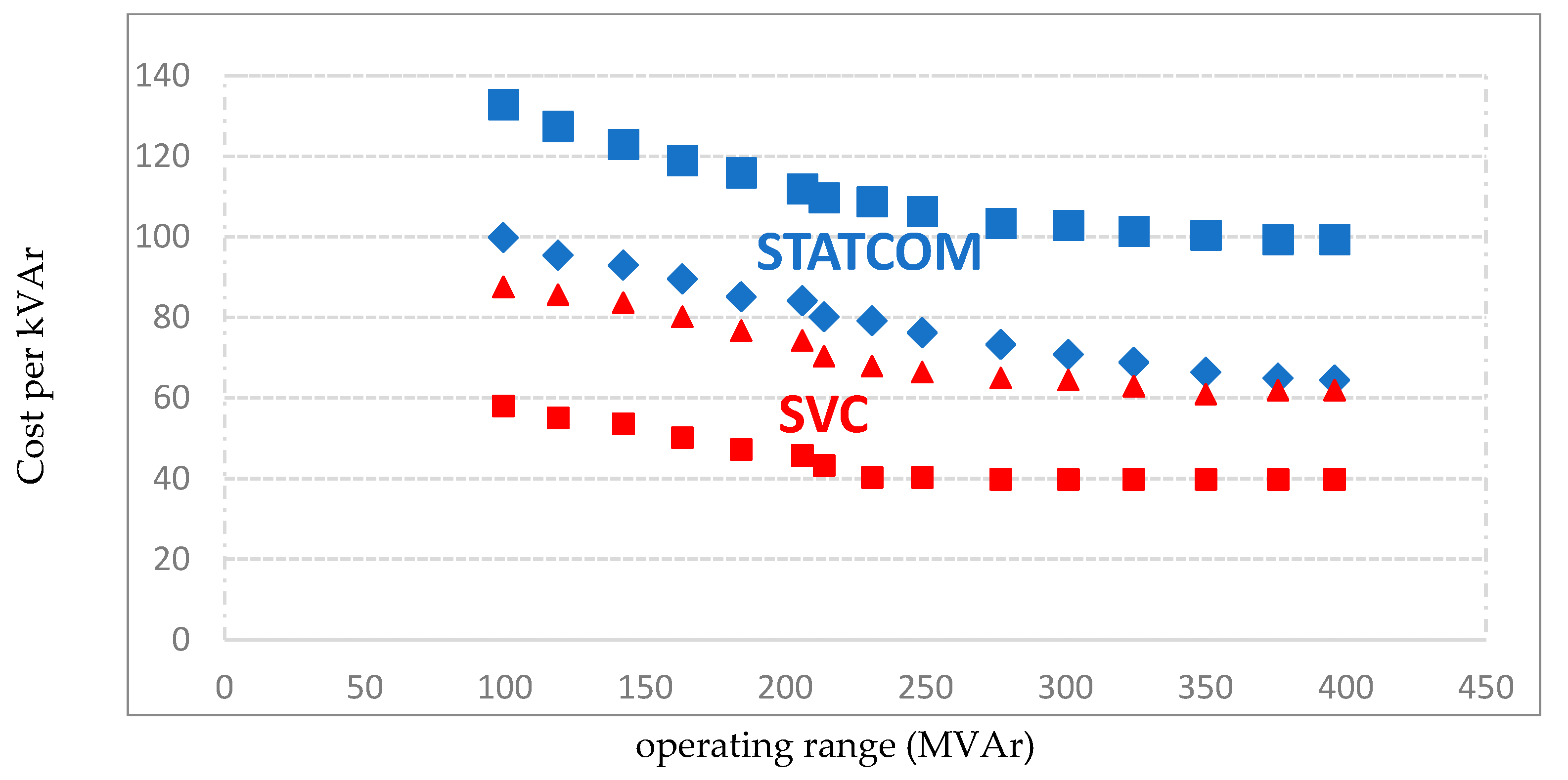
7. Economic Analysis of D-FACTS Systems

The global market for FACTS and D-FACTS systems is expected to reach $1,386,010,000 in 2018, it had already reached $912,850,000 in 2012 [12]. The D-SVC is the most widely used solution in the world market, followed by fixed capacitor banks. However, devices such as D-STATCOM are one customized solution for specific requirements of the distribution network. Obviously, some D-FACTSs are relatively expensive because they consist of many components such as advanced power electronics components, thyristors, reactors, capacitor banks, switches, protection systems and control systems. In this section, the range of the cost of the key features is often taken from the company Siemens and the Electric Power Research Institute (EPRI) with the database specified in [13], as shown in Figure 19.
Generally, the cost of a D-FACTS system has two components: the installation costs and operating expenses. The total cost of the entire installed systems comprises the equipment price and the delivery and installation of these systems. The operating cost includes the cost of maintenance and service. Specifically, the operating cost of these devices is approximately 5% to 10% of the total installation cost. Therefore, the cost functions for the D-SVC and D-STATCOM are developed as follows [15]:
{ C S V C = 0.0004 s 2 0.262 s + 81.5 C S V C = 0.0003 s 2 0.305 s + 127.38 C S T A T C O M = 0.0004 s 2 0.3225 s + 128.75 C S T A T C O M = 0.0008 s 2 0.155 s + 120
where s is the operating range of D-FACTS devices kVAr. The marginal cost per kVAr of the installed D-FACTS devices decreases as the operating rate of capacity increases. An overall cost for reactive power 100 MVAr, D-SVC ranges from $60 to $100 per kVAr. Although the D-SVC has sophisticated components such as thyristors, inductors and capacitors, it has a control structure that is relatively simple. Similarly, based on Figure 19, the overall cost of a D-STATCOM varies from $100 to $130 per kVAr and 100 MVAr of operating range. The costs of the installed parallel D-FACTS devices are shown in the Table 2 [16]:
From the above table, we see that the cost of D-FACTS devices (D-SVC and D-STATCOM) is much more expensive compared to capacitors due to the cost of the control devices and the complexity of the design and application of D-FACTS systems. The D-STATCOM is the source of reactive power compensation that is more expensive because of the used power electronics components like the Insolated Gate Bipolar Transistor (IGBT).
In this study, the Figure 20 summarizes the performance of both D-FACTS types (D-STATCOM and D-SVC), also by comparing the amount of injected reactive power (MVAr) and the installation cost of these devices ($). This comparison provides a basis for system integration D-FACTS in a wind farm consisting of the DFIG type of generator helping to achieve a better balance between performance and cost in the condition of specific defects.
The D-STATCOM provides a very effective reactive power compensation with respect to the D-SVC for all fault conditions. However, the D-SVC has a capacity option for a large amount of reactive power to be injected during a severe fault condition of the source. In the case of a two-phase ground fault (worst event of the grid fault applied in this study), the cost of installation is an important factor to consider. Therefore, in this paper, the economic analysis aims to compare the total cost of two types of parallel D-FACTS connected to a wind farm based on DFIGs, as presented in Figure 21.
According to Figure 21, it is clear that the use of D-STATCOM to maintain the wind farm in service during grid fault conditions is an expensive application compared with D-SVC due to the use of the transformer and the cost of power electronics [17,18]. Consequently, one can conclude that the D-STATCOM is more cost-effective compared to D-SVC for voltage support at the PCC and the wind farm connection in the event of the most severe grid fault conditions.
Figure 22 shows the cost breakdown of a proposed 12 MW wind farm installation.
According to this figure, it can be seen that the proposed solution based on a D-FACTS system represents only 4% of the overall cost of the wind turbine installation. On the other hand, this solution offers good performance at the wind farm, ensuring its connection with the electrical grid and the reliability of the wind energy conversion system.

8. Conclusions

The aim of this paper is to investigate the feasibility study of the wind farm project in an Algerian highland region. Nevertheless, the study in this paper shows that Tiaret’s electrical grid is susceptible to host the proposed wind farm in order to benefit from the wind potential. Therefore, in this paper, the application of the D-FACTS systems as the appropriate solution for the electrical grid connection issue and to accomplish the uninterrupted operation of a wind farm based on DFIG during the line-to-line fault and the voltage drop at 60 kV has been investigated. The D-FACTS is connected at the PCC where the wind farm is connected to the grid, to provide necessary reactive power for voltage support of the wind farm. Based on the simulation results, the stability improvement of the wind farm through the incorporation of the D-SVC or the D-STATCOM has been illustrated. In addition, it can be concluded that using D-STATCOM reduces the complexity of controlling the wind turbine-generators, improves the time response of reactive power compensation, and corrects for the lack of a wind turbine.
Future work will evaluate the impact of different scenarios for wind farms integrated into the Algerian electrical grid with other renewable energy sources and their electricity price.

Author Contributions

L.W. and K.D.E.K. contributed to the main idea of this article. K.D.E.K wrote the paper. K.D.E.K. searched literature. K.D.E.K collected data and performed the simulations. L.W., A.V.D.B., A.M., A.D. and K.D.E.K. contributed to the analysis of data. L.W., K.D.E.K., A.V.D.B., A.M., A.D. and L.B. revised the paper critically. All authors approved the final version to be published.

Funding

This research was funded by the National Natural Science Foundation of China grant number 51577005. No. 51877005 and the Aeronautical Science Foundation of China grant number 2015ZC51030.

Conflicts of Interest

The authors declare no conflict of interest.

Appendix A

In this part, simulations are investigated with a 1.5 MW DFIG connected to a 690 V/50 Hz grid [28,40,42,43]. The parameters of the turbine and the generator are presented below:
ParametersValues
Turbine
Number of blades3
Turbine radius35.25 m
Gear box ratio90
DFIG
Power1.5 MW
Nominal voltage690 V
Frequency50 Hz
Number of poles pair 2
Stator resistance0.012 Ω
Rotorique resistance0.021 Ω
Stator inductance0.0137 H
Rotor inductance0.01367 H
Mutual inductance0.0135 H
(Turbine + DFIG)
Generator inertia1000 Kg.m2
Friction factor0.0024 Kg.m/s
The parameters of the D-STATCOM are presented below [44]:
ParametersValues
Transformer voltage2.5/30 kV
Nominal frequency50 Hz
Rated power3–15 MVA
Resistance0.22/30 pu
Inductance 0.22 pu
DC-link voltage4000 V
The parameters of the D-SVC are presented below:
ParametersValues
Transformer voltage2.5/30 kV
Nominal frequency 50 Hz
Rated power3–15 MVA
Rated capacitor power3–15 MVar
Rated inductance power1.5–10 MVar

References

  1. Djalel, D.I.B.; Bendakir, A.; Metatla, S.; Soufi, Y. The algerian challenge between the dependence on fossil fuels and its huge potential renewable energy. Int. J. Renew. Energy Res. 2012, 2, 463–470. [Google Scholar]
  2. Souag, S.; Benhamida, F. A dynamic power system economic dispatch enhancement by wind integration considering ramping constraint-application to algerian power system. Int. J. Renew. Energy Res. 2015, 5, 794–805. [Google Scholar]
  3. Equilibres, La lettre de la Commission de Régulation de l’Electricité et du Gaz, N 12, Mars 2011. Available online: https://www.creg.dz/images/equilibres/Equilibres12.pdf (accessed on 1 Mars 2011). (In French).
  4. Programme des Energies Renouvelables et de l’Efficacité Energétique, Mars 2011. Available online: http://www.energy.gov.dz/francais/uploads/2016/Programme-National/Programme-National-Efficacite-Energetique.pdf (accessed on 1 Mars 2011). (In French)
  5. La Ferme Eolienne d’Adrar Mise en Service. Available online: http://portail.cder.dz/spip.php?article4098 (accessed on 3 July 2014).
  6. Miloud, F.S.B.; Aissaoui, R. Etude du potentiel éolien d’Adrar Sélection de sites pour la ferme éolienne de 10 MW. Séminaire Méditerranéen En Energie Eolienne 2010, 13, 295–300. [Google Scholar]
  7. Himri, Y.; Himri, S.; Stambouli, A.B. Assessing the wind energy potential projects in Algeria. Renew. Sustain. Energy Rev. 2009, 13, 2187–2191. [Google Scholar] [CrossRef]
  8. Maouedj, R.; Bouchouicha, K.; Boumediene, B. Evaluation of the wind energy potential in the Saharan sites of Algeria. In Proceedings of the 10th International Conference Environment and Electrical Engineering, Rome, Italy, 8–11 May 2011; IEEE: Piscataway, NJ, USA. [Google Scholar]
  9. Himri, Y.; Stambouli, A.B.; Draoui, B.; Himri, S. Techno-economical study of hybrid power system for a remote village in Algeria. Energy 2008, 33, 1128–1136. [Google Scholar] [CrossRef]
  10. Kasbadji Merzouk, N.; Merzouk, M.; Abdeslam, D. Prospects for the wind farm installation in the Algerian high plateaus. Desalination 2009, 239, 130–138. [Google Scholar]
  11. Abdeslam, D.; Kasbadji Merzouk, N. Wind energy resource estimation in Sétif region. In Proceedings of the Conference on the Promotion of Distributed Renewable Energy Sources in the Mediterranean Region, Nicosia, Cyprus, 11–12 December 2009. [Google Scholar]
  12. Dehmas, D.; Kherba, N.; Hacene, F.B.; Merzouk, N.K.; Merzouk, N.; Mahmoudi, H.; Goosen, M. On the use of wind energy to power reverse osmosis desalination plant: A case study from Ténès (Algeria). Renew. Sustain. Energy Rev. 2011, 15, 956–963. [Google Scholar] [CrossRef]
  13. Zin, A.A.B.M.; Mahmoud, H.A.; Khairuddin, A.B.; Jahanshaloo, L.; Shariati, O. An overview on doubly fed induction generators controls and contributions to wind-based electricity generation. Renew. Sustain. Energy Rev. 2013, 27, 692–708. [Google Scholar]
  14. Mohseni, M.; Islam, S.M. Review of international grid codes for wind power integration: Diversity, technology and a case for global standard. Renew. Sustain. Energy Rev. 2012, 16, 3876–3890. [Google Scholar] [CrossRef]
  15. Tazil, M.; Kumar, V.; Bansal, R.C.; Kong, S.; Dong, Z.Y.; Freitas, W. Three-phase doubly fed induction generators: An overview. IET Electr. Power. Appl. 2010, 4, 75–89. [Google Scholar] [CrossRef]
  16. Tsourakisa, G.; Nomikosb, B.M.; Vournasa, C.D. Effect of wind parks with doubly fed asynchronous generators on small-signal stability. Electr. Power Syst. Res. 2009, 79, 190–200. [Google Scholar] [CrossRef]
  17. Abdelhafidh, M.; Mahmoudi, M.O.; Nezli, L.; Bouchhida, O. Modeling and control of a wind power conversion system based on the double-fed asynchronous generator. Int. J. Renew. Energy Res. 2012, 2, 300–306. [Google Scholar]
  18. Kerrouche, K.; Mezouar, A.; Belgacem, K. Decoupled control of doubly fed induction generator by vector control for wind energy conversion system. Energy Procedia 2013, 42, 239–248. [Google Scholar] [CrossRef]
  19. Wang, Z.; Sun, Y.; Li, G.; Ooi, B.T. Magnitude and frequency control of grid-connected doubly fed induction generator based on synchronised model for Wind power generation. IET Renew. Power Gen. 2010, 4, 232–241. [Google Scholar] [CrossRef]
  20. Rolán, A.; Pedra, J.; Córcoles, F. Detailed study of DFIG-based wind turbines to overcome the most severe grid faults. INT J. Electr. Power 2014, 62, 868–878. [Google Scholar] [CrossRef] [Green Version]
  21. Moghadasi, A.; Sarwat, A.; Guerrero, J.M. A comprehensive review of low-voltage-ride-through methods for fixed-speed wind power generators. Renew. Sustain. Energy Rev. 2016, 55, 823–839. [Google Scholar] [CrossRef] [Green Version]
  22. Ananth, D.V.N.; Kumar, G.N. Fault ride-through enhancement using an enhanced field-oriented control technique for converters of grid connected DFIG and STATCOM for different types of faults. ISA Trans. 2016, 62, 2–18. [Google Scholar] [CrossRef] [PubMed]
  23. Red Eléctrica de España. REE. P.O.12.3. Requisitos de Respuesta Frente a Huecos de Tensión de las Instalaciones de Producción de Régimen Especial. Available online: http://www.ree.es/sites/default/files/01_ACTIVIDADES/Documentos/ProcedimientosOperacion/PO_resol_12.3_Respuesta_huecos_eolica.pdf (accessed on 8 May 2013). (In Spanish).
  24. Hammouche, R. Atlas Vent de L’Algerie; Publication Interne de L’office National de Météorologie: Alger, Algiers, 1990. [Google Scholar]
  25. Rachid, M.; Said, D.; Boumediene, B. Wind Characteristics Analysis for Selected Site in Algeria. Int. J. Comput. Appl. 2012, 56, 450. [Google Scholar] [CrossRef]
  26. Ettoumi, F.Y.; Sauvageot, H.; Adane, A.E.H. Statistical bivariate modelling of wind using first-order Markov chain and Weibull distribution. Renew. Energy 2003, 28, 1787–1802. [Google Scholar] [CrossRef]
  27. Himri, Y.; Malik, A.S.; Stambouli, A.B.; Himri, S.; Draoui, B. Review and use of the Algerian renewable energy for sustainable development. Renew. Sustain. Energy Rev. 2009, 13, 1584–1591. [Google Scholar] [CrossRef]
  28. Kerrouche, K.D.; Mezouar, A.; Boumediene, L.; Van den Bossche, A. Speed sensor-less and robust power control of grid-connected wind turbine driven doubly fed induction generators based on flux orientation. Mediterr. J. Meas. Control 2016, 12, 606–618. [Google Scholar]
  29. Cheggaga, N.; Ettoumi, F.Y. A neural network solution for extrapolation of wind speeds at heights ranging for improving the estimation of wind producible. Wind Eng. 2011, 35, 33–53. [Google Scholar] [CrossRef]
  30. Merzouk, N.K.; Merzouk, M.; Benyoucef, B. Profil Vertical de la Vitesse du vent dans la Basse Couche Limite Atmosphérique; JITH: Albi, France, 2007; pp. 1–5. [Google Scholar]
  31. Cheggaga, N.; Ettoumi, F.Y. Estimation du potentiel éolien. Revue Des Energies Renouvelables 2010, 99–105. [Google Scholar]
  32. Abbes, M.; Belhadj, J. Wind resource estimation and wind park design in El-Kef region, Tunisia. Energy 2012, 40, 348–357. [Google Scholar] [CrossRef]
  33. Boudia, S.M.; Benmansour, A.; Ghellai, N.; Benmedjahed, M.; Tabet Hellal, M.A. Monthly and seasonal assessment of wind energy potential in Mechria region, occidental highlands of Algeria. Int. J. Green Energy 2012, 9, 243–255. [Google Scholar] [CrossRef]
  34. Lakdja, F.; Gherbi, Y.; Hocine, G.; Adbsallem, D.O. Impact of STATCOM on a wind farm into the Western of Algerian network. In Proceedings of the International Renewable and Sustainable Energy Conference, Ouarzazate, Morocco, 17–19 October 2014; IEEE: Piscataway, NJ, USA, 2014. [Google Scholar]
  35. Mokhtari, A.; Gherbi, F.Z.; Mokhtar, C.; Kerrouche, K.D.E. Study, analysis and simulation of a static compensator D-STATCOM for distribution systems of electric power. Leonardo J. Sci. 2014, 25, 117–130. [Google Scholar]
  36. Sharma, P.; Bhatti, T.S.; Ramakrishna, K.S.S. Performance of statcom in an isolated wind–diesel hybrid power system. Int. J. Green Energy 2011, 8, 163–172. [Google Scholar] [CrossRef]
  37. Karimi, M.; Farhadi, P. Selecting the Best Compatible SVC Type in Power Systems for transient Stability. Int. J. Green Energy 2015, 12, 87–92. [Google Scholar] [CrossRef]
  38. Kerrouche, K.D.E.; Mezouar, A.; Boumediene, L.; Belgacem, K. Modeling and optimum power control based DFIG wind energy conversion system. Int. Rev. Electr. Eng. 2014, 9, 174–185. [Google Scholar] [CrossRef]
  39. Kerrouche, K.D.E.; Mezouar, A.; Boumediene, L.; Van Den Bossche, A. Modeling and lyapunov-designed based on adaptive gain sliding mode control for wind turbines. J. Power Technol. 2016, 96, 124–136. [Google Scholar]
  40. Kerrouche, K.D.E.; Mezouar, A.; Boumediene, L.; Van Den Bossche, A. A comprehensive review of LVRT capability and sliding mode control of grid-connected wind-turbine-driven doubly fed induction generator. Automatika 2016, 60, 922–935. [Google Scholar]
  41. Okedu, K.E. Stability enhancement of dfig-based variable speed wind turbine with a crowbar by facts device as per grid requirement. Int. J. Renew. Energy Res. 2012, 2, 431–439. [Google Scholar]
  42. Masaud, T.M.; Sen, P.K. Study of the implementation of STATCOM on DFIG-based wind farm connected to a power system. In Proceedings of the IEEE PES Innovative Smart Grid Technologies, Washington, DC, USA, 16–20 January 2012; IEEE: Piscataway, NJ, USA, 2012. [Google Scholar]
  43. Kerrouche, K.D.E.; Wang, L.; Van Den Bossche, A.; Draou, A.; Mezouar, A.; Boumediene, L. Dual robust control of grid-connected dfigs-based wind-turbine-systems under unbalanced grid voltage conditions. In Stability Control and Reliable Performance of Wind Turbines; Intechopen: Rijeka, Croatia, 2018. [Google Scholar]
  44. Kerrouche, K.D.E.; Wang, L.; Mezouar, A.; Boumediene, L.; Van Den Bossche, A. Fractional-order sliding mode control for D-STATCOM connected wind farm based DFIG under voltage unbalanced. Arab. J. Sci. Eng. 2018, 44, 1–16. [Google Scholar] [CrossRef]
Figure 1. Wind farm at Kabertene in Adrar. Reproduced for reference [5].
Applsci 08 02250 g001
Figure 2. Fault ride-through (FRT) profile according to the Spanish grid code. Reproduced from reference [23].
Applsci 08 02250 g002
Figure 3. Wind speed variations at different locations in Algeria.
Applsci 08 02250 g003
Figure 4. Annual wind speed in Algeria.
Applsci 08 02250 g004
Figure 5. Map of the western Algerian electrical grid. Reproduced from reference [1].
Applsci 08 02250 g005
Figure 6. Western electrical grid near to the proposed wind farm.
Applsci 08 02250 g006
Figure 7. In each bus of the 60-kV electrical grid in Tiaret region: (a) voltage amplitudes; (b) active powers.
Applsci 08 02250 g007
Figure 8. Reactive power in each bus of the 60-kV electrical grid in the Tiaret region.
Applsci 08 02250 g008
Figure 9. Control configuration of the distribution static var compensator (D-SVC) connected to the point of common coupling (PCC) with a wind farm.
Applsci 08 02250 g009
Figure 10. Control configuration of the distribution static synchronous compensator (D-STATCOM) connected to the PCC with a wind farm.
Applsci 08 02250 g010
Figure 11. Structure of the studied system based on a wind farm and a distributed-flexible AC transmission system (D-FACTS) connected to the Algerian distribution grid.
Applsci 08 02250 g011
Figure 12. Block diagram of the proposed system on Matlab/Simulink.
Applsci 08 02250 g012
Figure 13. (a) Voltage at the PCC during line-to-line electrical grid fault; (b) zoom of voltage at the PCC during line-to-line electrical grid fault.
Applsci 08 02250 g013
Figure 14. (a) Active power at the PCC during line-to-line electrical grid fault; (b) zoom of active power at the PCC during line-to-line electrical grid fault.
Applsci 08 02250 g014
Figure 15. (a) Reactive power at the PCC during line-to-line electrical grid fault; (b) zoom of reactive power at the PCC during line-to-line electrical grid fault.
Applsci 08 02250 g015
Figure 16. Voltages at the PCC during the voltage drop at the 60 kV bus.
Applsci 08 02250 g016
Figure 17. Active power at the PCC during the voltage drop at the 60 kV bus.
Applsci 08 02250 g017
Figure 18. Reactive power at the PCC during the voltage drop at the 60 kV bus.
Applsci 08 02250 g018
Figure 19. Cost of the operation range for different D-FACTS devices. Reproduced from [14].
Applsci 08 02250 g019
Figure 20. Reactive power injected into the PCC by using D-SVC and D-STATCOM with different types of grid faults.
Applsci 08 02250 g020
Figure 21. Cost of D-FACTS systems from different types of grid faults.
Applsci 08 02250 g021
Figure 22. Breakdown of the costs of the wind project.
Applsci 08 02250 g022
Table 1. Coordinates of stations at different Algerian sites.
StationCoordinates
Altitude (m)Latitude (deg)Longitude (deg)
South region (Sahara)
Adrar26327°49′ N00°17′ W
Ghardaia 46832°24′ N03°48′ E
Coastal region
Algiers 2436°43′ N 03°15′ E
Oran9035°38′ N00°37′ W
Highland region
Tiaret 1080 35°37′ N01°32′ E
Table 2. Costs of different reactive power compensators.
Parallel Reactive Compensator Cost (US $/kVar)
Shunt capacitor 8/kVar
D-SVC60/kVar
D-STATCOM100/kVar

