On Localized Countermeasure Against Reactive Jamming Attacks in Smart Grid Wireless Mesh Networks


1
Department of Information Security, Mokpo National University, Youngsan 1666, Muan, Jeonnam 58554, Korea
2
Department of Computer Engineering, Myongji University, Myoungji 116, Yongin, Kyounggi 17058, Korea
*
Author to whom correspondence should be addressed.
Appl. Sci. 2018, 8(12), 2340; https://doi.org/10.3390/app8122340
Submission received: 10 October 2018
/
Revised: 1 November 2018
/
Accepted: 16 November 2018
/
Published: 22 November 2018
(This article belongs to the Special Issue Smart Grid and Information Technology)
Abstract
:Reactive jamming attacks have been considered as one of the most lethal and disruptive threats to subvert or disrupt wireless networks since they attack the broadcast nature of transmission mediums by injecting interfering signals. Existing countermeasures for the Internet against reactive jamming attacks, i.e., channel surfing or frequency hopping, demands excessive computing resources, which are infeasible on the low cost resource constraint of the electrical devices in the Smart Grid wireless mesh networks. Even these are inadequate protect approaches to the control systems where the availability is the major security priority to achieve. To overcome the problems for normal lower computation power electrical devices in the Smart Grid wireless mesh networks with difference security triad from the Internet, we propose an efficient localized jamming-resistant countermeasure against the jamming attacks by the identification of trigger nodes whose wireless signal invokes the jammer in the grid. By constraining the trigger nodes to be receivers only, we can avoid the activation of the jammers and completely nullify the reactive jamming attack. The triggers identification approach utilizes a hexagon tiling coloring and sequential Group Testing (GT), which does not demand any sophisticated hardware. Theoretical analyses and simulation results endorse the suitability of our localized algorithm in terms of message and time complexity.
1. Introduction
The Smart Grid propels the transition from the traditional and conventional electrical power grid into the modern grid by solving the issues of increasing demand on electrical energy, unidirectional power/information delivery, energy wastage and resilience on the power grids. The dramatic transition over the demand on the electrical energy from the tremendous and rapid increasing number of electronic devices since 1970 has caused the increasingly serious energy shortage and carbon emission in power systems. Furthermore, the existing power grids struggle with other challenges from the depletion of fossil fuel, such as reliability of the aging infrastructures and even security issues. However, the advent of Smart Grid paradigm has appeared as a promising model of advanced power grid that would be constructed over the existing grid with a variety of information and communication technologies. The Smart Grid realized by bi-directional communication technologies would achieve the improvement of the effectiveness, efficiency, reliability, security, sustainability, stability and scalability over the traditional power grid systems [1].
The Smart Grid differentiates itself from the conventional grid not only in several benefits but also in security aspects. First of all, a bi-directional communication between service providers and consumers in the Smart Grid would drastically reduce electrical energy wastage by Demand Response (DR) service, such as real-time pricing and power consumption scheduling. Such efficiency on electricity consumption could achieve improvement on power quality but would inevitably result in the expansion of threat vectors to the advanced grid [2]. Secondly, the modern grid networks built with a wide range of various communication mediums and protocols deliver critical control messages as well as information, which shifts the order of the security triad from Credentiality, Integrity and Availability (CIA) in the Internet into AIC. In the Industrial Control Systems (ICS) domain, such as the Smart Grid, the destabilization of assets is the most critical security threat caused by the unauthorized acquisition of proprietary information in the Internet [3]. Consequently, the increasingly prevalent networked power infrastructure with the operational technologies would be the primary security target; it would compromise the resilience and robustness of the system, but the security approaches for the knowledge-based systems would not be able to guarantee the survivability of the grid.
There are various kinds of Denial-of-Service (DoS) threats, among which, jamming attacks have been known as the most significant threats because of their effectiveness and lethal damage against wireless networks in [4]. In a jamming attack, malice disseminates out adversarial signals into busy channels which are filled with legitimate device transmissions without following any legitimate protocols. This will result in the slump of the Signal-to-Noise ratio (S/N) and the performance of throughput in the networks.
This light weight wireless DoS attack is favored and convenient to launch due to the fact that the jammers do not have to breach into the wireless networks in order to exploit the structural configurations on the critical networks. In the scope of wireless DoS attacks, reactive jamming poses the maximum threats while requiring the lowest attacker energy against the networks. In essence, the reactive jamming attack is the most efficient attack strategy and it is extremely difficult to be discovered, in which a malicious node (jammer) quietly scans all the available channels to sense any activity and blatantly starts injecting adversarial signal on that channel. Especially, in accordance with Wenye Wang and et al. in [1], wireless mesh networks become both an economical and efficient communication approach to be employed in order to monitor and control the tremendous number of field devices in the Smart Grid. Thereupon, the reactive jamming attacks to the wireless mesh networks in the Grid would adversely affect the operation of overall electrical systems and cause devastating consequences to the critical infrastructures.
Existing defensive methods against reactive jamming threats can be broadly studied on the physical, link and network layers. Firstly, the physical layer approaches [5,6,7,8,9] generally use Code Division Multiple Access (CDMA) and Frequency Hopping (FH) which require a high computational cost. MAC layer approaches [10,11] are either inherently based on FH or re-positioning the wireless nodes, which may result in network partitioning and bring in high computation overhead. Finally, in the network layer approach, ref. [12] introduces a new scheme to quarantine possible jammed areas and re-route all the messages that originally pass this area. However, the JAM method could produce unnecessarily large jammed areas and even result in isolated wireless networks. Furthermore, during the jammed area mapping procedure, the higher communication overhead from the message exchange among the wireless devices might slow the performance of the network throughput.
In our preceding work [13,14], we introduced the novel concept of trigger device, which refers to the wireless node whose transmission of wireless messages invokes the disruptive jamming signal. The detection of trigger devices has several benefits for the defense against the reactive DoS attacks: (1) Routing algorithm could be re-constructed in which the triggers do not transmit wireless messages but receive, consequently eliminating the activation of the jamming devices and mitigating the damage on the wireless networks. The identification of trigger would be able to overcome the drawbacks on the approaches of frequency hopping and channel surfing in requiring excessive computational resources. In the worst case where a trigger device wants to transmit messages, the utilization of physical layer approaches is still available, however, only a small number of triggers may be needed in our method in the case of broadcasting messages through the networks. Furthermore, the defensive method of identifying trigger devices squeezes the unnecessarily large jammed regions, the transmission range of jammers, compared to results from JAM approach in ref. [12]. (2) After identifying triggers, victim devices in the jammed areas could be lined up for the transmission of wireless messages such that no jammer would be activated, and whenever the trigger nodes start to broadcast, all other victim nodes stop their transmission. Thus preventing them from being jammed. (3) The location of triggers can be used to spot the place where jammers are planted as well. Therefore, with accurate and efficient identification of trigger nodes, a number of effective defense strategies can be developed. However, this trigger detection procedure is non-trivial, due to the unknown and dynamic locations of jammers and their various behaviors. To this end, we propose a localized trigger detection algorithm which employs two techniques: a hexagon tiling coloring scheme and a sequential Group Testing (GT), which efficiently identifies all the trigger nodes without requiring any extra hardware on wireless devices. Different from our previous work in ref. [14], this method can be distributedly implemented with a low time and message complexity for the Smart Grid wireless networks.
The rest of this paper is structured as follows: Section 2 provides a literature survey regarding the existing countermeasures on the jamming attack issues. In Section 3, we address the Smart Grid wireless network and the jamming model with the problem description. Section 4 discusses the fundamental results of our approach along with our proposed hexagon tiling coloring technique. The localized algorithm for identification of the trigger nodes is depicted in Section 5 and the theoretical analyses are presented in Section 6. In Section 7, we conduct a set of experimental evaluations on our solution against the jamming attacks. Finally, Section 8 concludes the paper.
2. Related Work
The jamming attacks to wireless networks are evolving at a higher rate than their available preventive countermeasures. The main objective of a jamming attack is to effectively jam the communication within the networks without being discovered and located. In the literature, there are various countermeasures proposed against different jamming attack models. Based on different techniques and the technology involved, the solution can be broadly classified into: (1) Physical layer approaches, (2) MAC layer approaches and (3) Network layer approaches.
The countermeasures against the jamming attack at the physical layer makes use of technologies such as FH spread spectrum [5,6,7] and Direct-Sequence Spread Spectrum (DSSS) [8,9] which requires very excessive computational resources. In ref. [6], Reed et al. introduced FH against jamming attacks by shifting the wireless communication frequency to secure one so as to dodge the jammed communications according to channel sequences generated by shared secret Transmission Security Key (TRANSEC). To solve the leftover problem of how to distribute the TRANSEC key in this method, Strasser et al. [7] proposed an Uncoordinated FH (UFH) scheme as a point-to-point anti-jamming manner. Due to the fundamentally low spectral efficiency from the design of proactive hopping procedure, a message driven frequency hopping technique has been recently introduced to achieve higher efficiency [5]. Using CDMA technology, Chiang et al. in ref. [8] proposed a countermeasure for the jamming attack, but as the approach is based on a dynamic tree reemerging scheme, there is a huge maintenance overhead and furthermore, computing the orthogonal codes is required with a considerable amount of latency. In ref. [9], using CDMA technology, Desmedt et al. propose a solution for the jamming attack but it involves the issue of common key sharing problem.
In ref. [11], Xu et al. introduced the channel surfing against jamming attacks at MAC layer. This approach is inherently based on FH and switches channel in an on-demand manner. The important issues involved in this approach are scalability, latency and synchronization of coordinated communication channel shifting across the network. Furthermore, in ref. [10], Xu et al. introduced a spatial retrieval method, where a mobile node is physically repositioned out of jammed region, but this may result in parts of the network getting isolated. In addition, Fang et al. in ref. [15] introduced a link layer countermeasure technique to solve the critical challenges in exploring the un-jammed survived bits in wireless messages from the reactive jamming attacks in order to re-assemble them into the originally transmitted messages. This literature provides the system delivering wireless messages by harnessing the invocation time of the reactive jammer, but it could not avoid the activation of the jammer.
In addition, a linear programming based countermeasure in ref. [16] has been introduced against a wireless jamming threat to disrupt network flow. However, such types of solutions are not practical as they cannot be implemented in real time in the Smart Grid wireless mesh networks. In ref. [12], Wood et al. proposed a solution at the network layer level, where the jammed nodes cooperatively identify the jammed region and a path is identified to detour this jammed region. The problem with this approach is that it may result in a considerably large part of the isolated network.
Besides the countermeasures described above, an area mapping based defense from the network layer has been investigated in JAM [12]. In this approach, the wireless devices under the jamming attack would map cooperatively the jammed area a path in order to detour communication messages around the identified area. A deficiency on the scheme would be the possibility of creating unnecessarily large jammed area to avoid the jamming attack, which might result in the isolated networks. That is, a large number of devices in the area that is considered as the jammed area from the JAM approach could still transmit wireless messages without any activation of jammers in accordance with our solution.
In contrast, our localized algorithm which is based on hexagon tiling coloring and sequential group testing overcomes the shortcomings mentioned above. Specifically, our solution focuses on the network layer, which does not require any modification of the lower layers. In addition, no unnecessary triggers would be disabled from our solution; the jammed region would be much smaller than in ref. [12], thus our defense is more efficient.
3. Network and Jamming Models
3.1. Smart Grid Wireless Mesh Network Model
We model a general wireless mesh network in the Smart Grid consisting of n wireless device nodes in refs. [1,17]. Each device node has the constant wireless communication range r. Thus, the wireless mesh network can be considered as a Unit Disk Graph (UDG) , where V denotes the group of devices and E represents the group of wireless communication connections. Where implies the Euclidean distance from u to v and vice versa, there exists a link iff between any two Smart Grid device nodes .
We further consider a set of jammers J existing at unknown locations in the network having a transmission range at most where . Note that if two jammers have a distance less and equal to R, they may consider the signals from each other as some activity in the network and keep injecting until their energy is depleted. Thus, we may consider the distance between any two jamming devices to be larger than R.
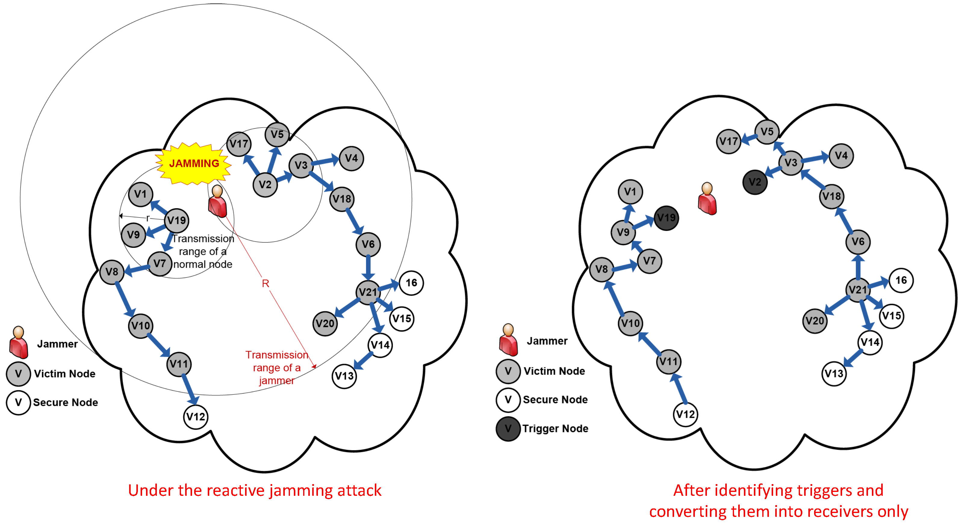
Any Smart Grid wireless communication node is said to be a trigger node if there is a jammer , such that . That is, when u transmits, it inevitably invokes the jammer j. A device node v is said to be a victim node, iff . (Note that by definition, a trigger node is always a victim node). If a jammer is invoked, then all the victim nodes within its transmission range are jammed from receiving any messages.
3.2. Jamming Model
The Reactive Jamming Attack (RJA) model was first defined in ref. [18]. In this model, a jammer continuously scans all the available channels in the network to sense some activity. As soon as it senses a signal on some channels, it injects an adversarial signal (we call this signal in this paper) to drastically decrease the signal to noise ratio and communication throughput of that channel.
This paper utilizes the RJA model explained above. Generally, the duration for the transmission of by the jammer is larger than or equal to the duration for transmission of a trigger node. For instance, let the duration for transmission of a trigger node be and the duration for the transmission of from the jammer be . Then if , after time the jammer will be done with its transmission, but still it will sense some signal on the channel. So, the jammer will again start sending the signal and it repeats this until it detects no signal on the channel. Therefore, should be less than or equal to .
3.3. Problem Statement
Given a Smart Grid wireless mesh network and a group of jammers J. Considering the above network and jamming models in the Figure 1, our goal is to efficiently detect all the devices activating the jammers in the network with low message and time complexities. We would be able to use the triggers information to construct an overlying routing protocol where trigger nodes are receivers only, so that the invoking of any jammer is avoided and the reactive jamming attack is completely nullified.
4. Overview and Fundamental Results
This section presents a brief overview of the localized solution along with some fundamental results that will be used later. Our localized algorithm can be implemented as a network maintenance service and can be periodically invoked to identify all the trigger nodes. As discussed earlier, the identification of trigger devices can provide an efficient defense against the reactive jamming threats by converting triggers to receivers only in the overlaying routing protocols, thus avoiding activating jammers. We will use testing to identify these trigger nodes by allowing them to send out a test message and listen if there is any noise. However, individual testing is too time-consuming, thus we often test a number of nodes, called group testing (GT). However, testing a group of nodes simultaneously encounters several difficulties. For example, if some Noise is sensed after performing testing, we may not know which ones in the tested nodes triggered the jammers. Moreover, scheduling nodes in a testing group to perform the testing synchronously may result in a lot of communication overhead in the network if tested nodes are far from each other. In addition, if two group of nodes are testing at the same time and the jammer triggered by the first group can jam nodes in the second group, the testing result may be inferred incorrectly. Hence, an efficient grouping and scheduling is essential to reduce the overall latency.
We utilize two principles to efficiently reduce the number of testing rounds i.e., overall latency:
- If two nodes u and v are at the distance at least they cannot trigger the same jammer. This enable us to test in a same round without having the outcome of testing u and that of v interfered each other. In general, we can perform testing in parallel for two sets of nodes U and V that are far away from each other.
- If and w are identified triggers, then all nodes inside the triangle whose vertices are are also triggers. Furthermore, if is a set of triggers, then all the nodes inside the convex hull of T are also triggers. This holds as long as .
4.1. Overview of Identification Procedure
The overview of the trigger identification procedure is depicted as follows: The sets of nodes are locally divided into hexagonal groups, and each hexagonal group is colored into disjoint interference-free groups, where the transmission of nodes within a group will not activate the same jammer whose adversarial signals will disrupt the communications with other groups. The diameter of each hexagon is small enough so that all nodes in the same hexagon can communicate with each other directly and hence the latency of forwarding messages is avoided. These groups are called testing groups in the remainder of this paper. The set of nodes within testing groups with the same color are then scheduled to fulfill a sequential GT procedure simultaneously in order to identify all trigger nodes over each testing group. Notice that all nodes in a network do not need to exchange additional messages in order to partition themselves into disjoint groups (to be explained in detail later) and run a sequential GT procedure since the basic premise of the Smart Grid wireless mesh networks in this paper are synchronized loosely in the order of seconds.
The trigger identification algorithm within each pool uses Sequential Group Testing (SGT) to detect only the Smart Grid wireless devices on the convex hull of the group of trigger devices which is much less than the size of triggers.
In principle, the description of the identification procedure is: (1) Partition the set of nodes into hexagonal testing groups; (2) Assign colors to hexagons in order to maximize the number of disjoint interference-free testing groups and schedule them according to the colors; (3) Perform sequential group testing within each hexagonal testing group during the assigned time slot for each group, in order to discover all trigger nodes.
How to divide the set of nodes into interference-free testing groups and how to discover all trigger nodes within minimum latency play fatal roles in our localized approach against reactive jamming attack and will be described with the theoretical analysis in the following sections.
4.2. Hexagon Tiling Coloring
This section introduces a hexagon tiling coloring scheme, which will be utilized later in Section 5 to locally partition the wireless devices in a given Smart Grid wireless mesh network into a series of testing groups.
The definition of the problem to design a hexagon tiling coloring algorithm is as follows:
The distance between two hexagons is defined as the Euclidean distance between any two closest points and in and respectively.
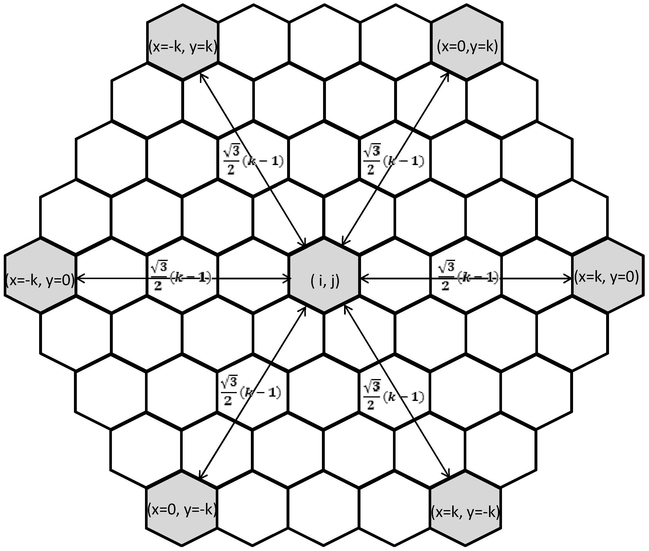
It can be observed in Figure 2 that in a hexagonal tilling, the centers in all the hexagons are located on a triangular lattice. As a result, a new coordinate system with inclined axes in the 2D plane is considered along with two unit vectors and as described in Figure 2. In the 2D plane, each center in every hexagon h coincides with the integral coordinates. In addition, each center of hexagon h is represented as with the coordinates . denotes the Euclidean distance between two centers of different hexagons and .
4.3. The -Coloring Algorithm
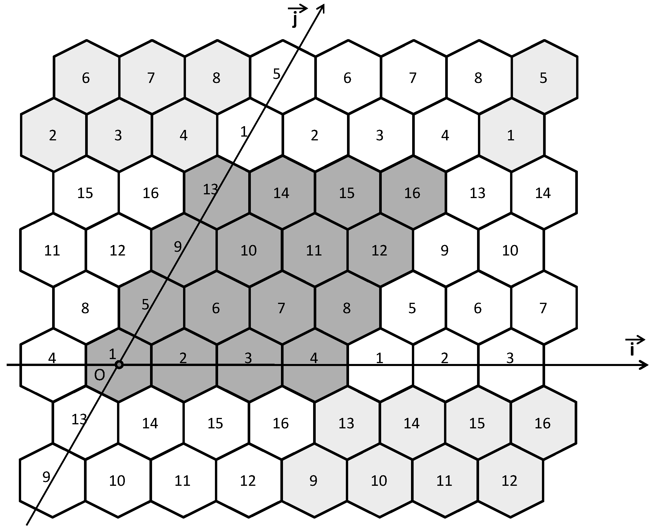
Now the -coloring algorithm is introduced for the problem of hexagon tiling coloring. For a given distance , the -coloring algorithm requires colors to paint the entire hexagon tiling h where and guarantees that any two hexagons with have different colors. Figure 3 indicates a coloring pattern of h generated by the -coloring algorithm where and . The -coloring algorithm is employed by Smart Grid wireless device nodes in our proposed localized algorithm to locally identify the group they belong to.
Lemma 1.
Where a distance , the -coloring algorithm paints the hexagon tiling area H, in a way that two different hexagons have their own distinct colors if .
Proof.
The proof of this lemma can be shown as that in the color assignment, for two different hexagons , painted by the coloring Algorithm 1, the distance will be larger than (with ).
If the colors from the -coloring algorithm painted in both and are the same, then . This is if and only iff
Let and , and it follows that x and y will be multiple of k. The distance between the centers of and is given by
Consider the following cases as:
- : where represents the Euclidean distance between the centers of two hexagons and . Since the distance from the center of a hexagon to a certain point inside cannot exceed , the distance between them will be at least .
- : We also obtain the same result as in the case .
- and : If , then the distance will be larger or equal to . Otherwise, only six cases of are left as depicted in Figure 2, and is the only distance between two hexagons with all the cases.
Consequently, the lemma is proved completely. □
5. Localized Trigger Identification Algorithm
As stated above, partitioning all nodes into testing groups will be done by hexagonal tiling and coloring scheme and each hexagonal testing group conducts sequential GT for the identification of all trigger devices based on their own colors. In this section, we will look into those algorithms in detail.
5.1. Partitioning Wireless Devices Based on the Algorithm of Hexagon tiling and coloring
In this section, we discuss the localized partitioning of the Smart Grid wireless devices into groups. A 2D plane on which the Smart Grid wireless mesh network is projected is to be partitioned into a regular hexagons in order to form a hexagon tiling, all the wireless devices deployed within the same hexagon form a testing group. Let be the diameter of a hexagon as follows:
- when
- when
- when
In accordance with all the cases above, the wireless devices deployed in the same hexagon have a distance less than or equal to r. Consequently, those devices would be able to exchange wireless messages in one hop.
We now discuss a localized method that a Smart Grid wireless device node can employ in order to find a hexagon, a testing group, that it belongs to. By using the Algorithm 1, a node can identify the color of its hexagon and also the time slot assigned to its group in the schedule. We consider that a node maintains a list of its neighbors and can calculate its location as with respect to reference devices by exploring ad hoc positioning scheme in refs. [19,20]. Within a Smart Grid wireless mesh network, we consider the sink device as the reference device such that . Then, we prove that if v, a Smart Grid wireless device, in the Cartesian system recognizes its coordinates without the knowledge of the global view on the hexagon tiling, it would be able to locally calculate its coordinates in a new coordinate system on the hexagon tiling. Furthermore, it learns the hexagon (testing group) that it belongs to.
| Algorithm 1:-Coloring Algorithm |
 |
In order to show the correctness of our method, we prove the following lemmas:
Lemma 2.
When , all trigger nodes located in a hexagon h trigger a single common jammer.
Proof.
Assume that there exists a hexagon h which has two trigger nodes and triggering two different jammers and , respectively. Now, when , , then and , hence, in this case , which is a contradiction as . Similarly, when , , , hence, which is again a contradiction. □
Lemma 3.
A node v located in a hexagon cannot be affected by the injected by a jammer j invoked by trigger nodes located in another hexagon , where .
Proof.
Assume that the injected by the jammer j affects node v, then and as , so , but as , so , which is a contradiction. □
Lemma 4.
Given , the number of colors c generated by Algorithm 1 to paint the entire hexagon tiling h is:
- , when .
- , when .
Proof.
In general, if a hexagon tiling H has hexagons of diameter , then considering a distance the -coloring algorithm needs colors, hence, it is straightforward to show that when:
- and ,-coloring algorithm needs colors
- and ,-coloring algorithm needs colors
□
5.2. Trigger Nodes Detection Procedure
This subsection illustrates how to resort to sequential GT and convexity of trigger nodes so as to identify all trigger nodes with minimum testing latency in each hexagonal testing group. For each node i of hexagonal testing group of color j, we devised the TNI-SGT algorithm (Trigger Node Identification based on Sequential GT) to detect all trigger devices during all testing groups with the same color to be tested simultaneously.
It is reasonable to set each testing round with a predefined constant time slot since each hexagonal testing groups with the same color conduct sequential GT procedure at the same time, and no new testing round would start until activated jammers turn themselves into listening mode. As mentioned, we consider that our network systems are loosely synchronized in the order of seconds.
As stated in Lemma 2, based on the constraint on distance between any two jammers and , in order to avoid mutual invocation between them, we proved that only one jammer can be activated by nodes within a hexagon.
5.2.1. Trigger Node Identification Based on Sequential Group Testing Algorithm (TNI-SGT)
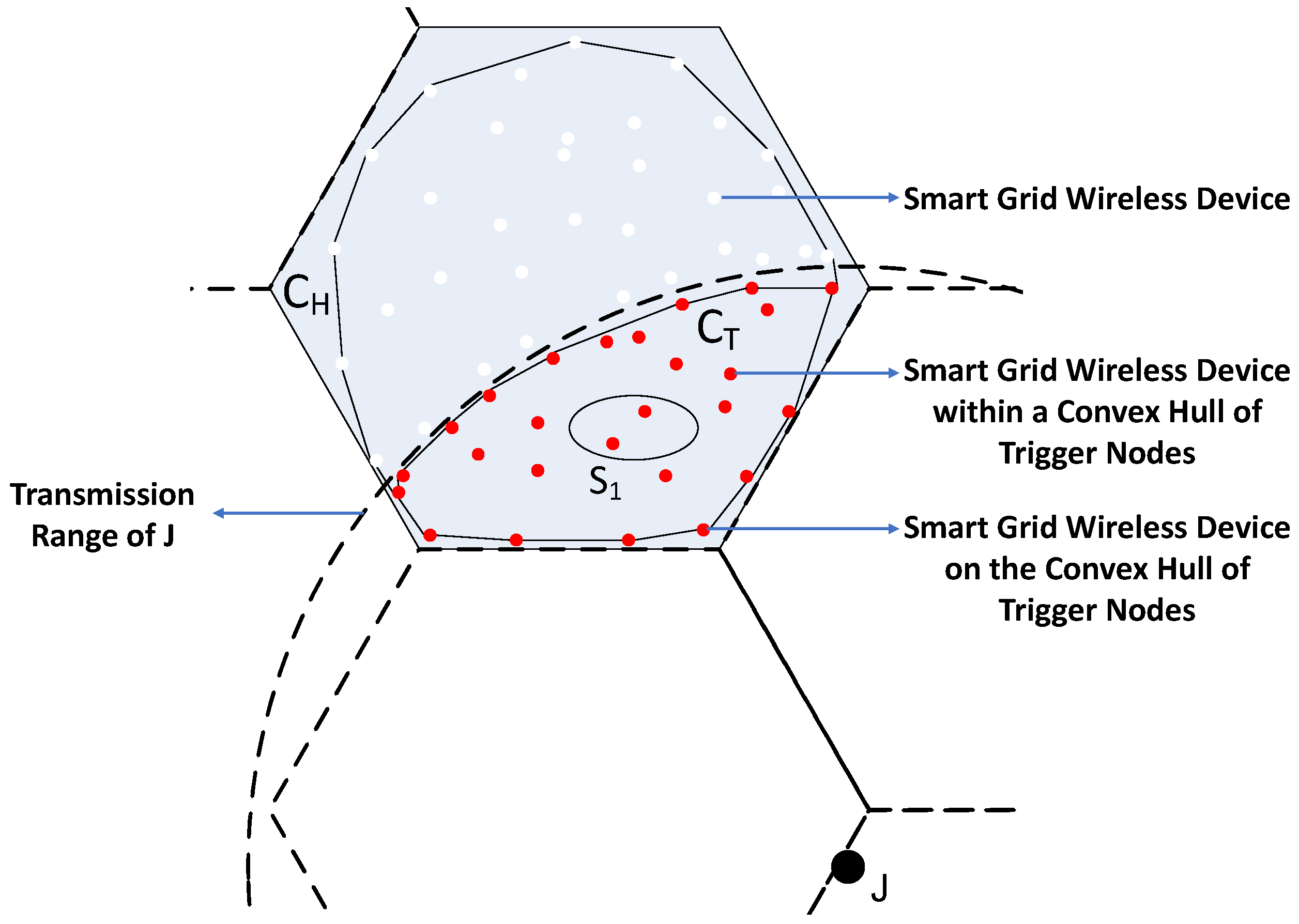
In accordance with the TNI-SGT algorithm, the identification of trigger nodes has the time complexity of when denotes the convex hull of triggers within a hexagon (see Figure 4). As a result, there are no more than devices in a certain hexagon, where indicates the maximum degree of all wireless devices in a Smart Grid wireless mesh network.
We design an additional scheme named Quick Identification so as to minimize the group testing rounds. As described in the Lemma 2, due to the fact that all the triggering devices within a hexagon invoke an identical jammer, a device is a trigger iff its location is at the intersection between any two hexagons with transmission range r whose center of transmission disk is the jamming device. The intersected convexity region guarantees that entire wireless devices within a triangle area established by three identified triggers are trigger devices as well. In essence, since all the wireless devices within the convex hull constructed by the identified triggers are triggers as well, no further testing is required for those devices.
Algorithm 2 describes the complete TNI-SGT. U and T represents a group of unidentified devices and identified triggers respectively in every step of the algorithm. We employ the ISTN algorithm to locate a single trigger device among U that locates with the maximum distance to the arbitrary convex hull of T. In addition, must reside in the convex hull of entire triggers inside the hexagon, which will be provided later.
| Algorithm 2: Trigger Node Identification based on Sequential Group Testing Algorithm (TNI-SGT) |
 |
We would be able to remove all wireless devices whose locations from the convex hull of T are greater than that of . The algorithm of the Quick Identification can reduce the testing latency by including all trigger devices inside the new convex hull of . After the classification of entire devices in each hexagon into non-triggers or triggers, the algorithm completes the testing procedure of identifying trigger nodes.
5.2.2. Identification of a Single Trigger Node (ISTN) Algorithm
The ISTN algorithm in Algorithm 3 illustrates the localized process to identify a trigger device with maximum ‘index’ among an ordered set U. It divides sequentially the group into two halves, similar to the binary search manner. However, the algorithm always performs the group testing to detect the presence of the wireless trigger devices in the right half first so that the one with the maximum index (the rightmost) would be returned, when there are triggers among U. The ISTN algorithm finalizes the process whenever a trigger device is located. In a clear sense, the identification of a trigger among a group U from the Smart Grid wireless devices from the algorithm ISTN requires at most testing rounds.
| Algorithm 3: Identification of A Single Trigger Node Algorithm ISTN based on Sequential Group Testing |
 |
6. Theoretical Performance Analysis
6.1. Upper Bound on Testing Rounds
Lemma 5.
Trigger identification ends as soon as all triggers in the convex hull are identified.
Proof.
All other triggers are also detected following Quick Identification. One more round of group testing for all the remain nodes will show there are no more triggers among them. □
Theorem 1.
Algorithm 2 requires no more than number of rounds where is the number of vertices on the convex hull of the set of triggers.
Proof.
The key observation is that in every round of the while loop, the chosen by ISTN will have the maximum distance to the arbitrary convex hull of the identified triggers (since the nodes in U are sorted based on the distance to that convex hull). That point must belong to the convex hull . Hence, the algorithm loops for at most times and requires at most round. □
Since we can perform testing for all hexagons of same color at the same time, the total number of rounds to identify all triggers in the network will be where c is the number of colors in Lemma 4 and is the maximum size of convex hull of a group of triggers in a hexagon. Although may go up to , the algorithm’s performance is often far better than its worst case.
6.2. Message Complexity
Lemma 6.
In Algorithm 2, the number of messages sent by nodes inside a hexagon H is where are the number of nodes, triggers inside H respectively.
Proof.
In the first phase of Algorithm 2 checking for the existence of triggers requires all nodes within the hexagon transmit at once. Hence, it costs messages.
In the second phase, identifying one trigger node among nodes using algorithm will cost messages. The number of message in the second phase is, hence, at most .
Adding the numbers of messages in two phases we get . □
Adding the number of messages in all possible hexagons we get the following theorem.
Theorem 2.
The total number of messages required to identify entire triggers node in the network is when n is the sum of devices and t is the sum of triggers in the wireless network.
7. Experimental Results
An intensive series of experimental simulations has been conducted in order to validate the theoretical proof and the effectiveness of the TNI algorithm against the feasible reactive jamming threat in the Smart Grid wireless mesh networks. Accurately, our solution, TNI approach, is comprised of two types of jamming signal testing schemes, Sequential Group Testing (TNI-SGT) and TNI using Individual Testing (TNI-IT). In this section, the experimental comparison of both methods is to be simulated and illustrated in terms of effectiveness on Group Testing against wireless security threats. Furthermore, the computational performance, latency, message overhead and the size of quarantine areas, from the TNI algorithm against the wireless DoS threat is to be compared and assessed to the outputs from the JAM approach in ref. [12] as well.
The objective on the set of experimental investigations in this section is to evaluate our solution in various Smart Grid wireless mesh networks by several teams of parameters in the transmission ratio between jammers and wireless Smart Grid devices, varied from to , and the network densities from growing number of nodes, to , and jammers, at most . Moreover, the initiative group of parameters on the Smart Grid wireless network is that jammers and the wireless devices are randomly deployed by the pseudo-uniform distribution manner in an area 1000 m × 1000 m along with the transmission range m.
Since the implementation of this experimental simulation is to evaluate the performance of identifying trigger devices against the jamming threat only, MAC misbehavior, link-congestion, packet losses except the disruptive signals from jammers are not considered. The experiments with each configuration from above are iterated 100 times and averaged to depict in graphs, so that the analysis on the results would suffice to show the efficiency of TNI algorithm. Furthermore, we implemented our experimental simulation on the Linux with kernel version 4.13 by leveraging igraph library.
7.1. Results and Analysis
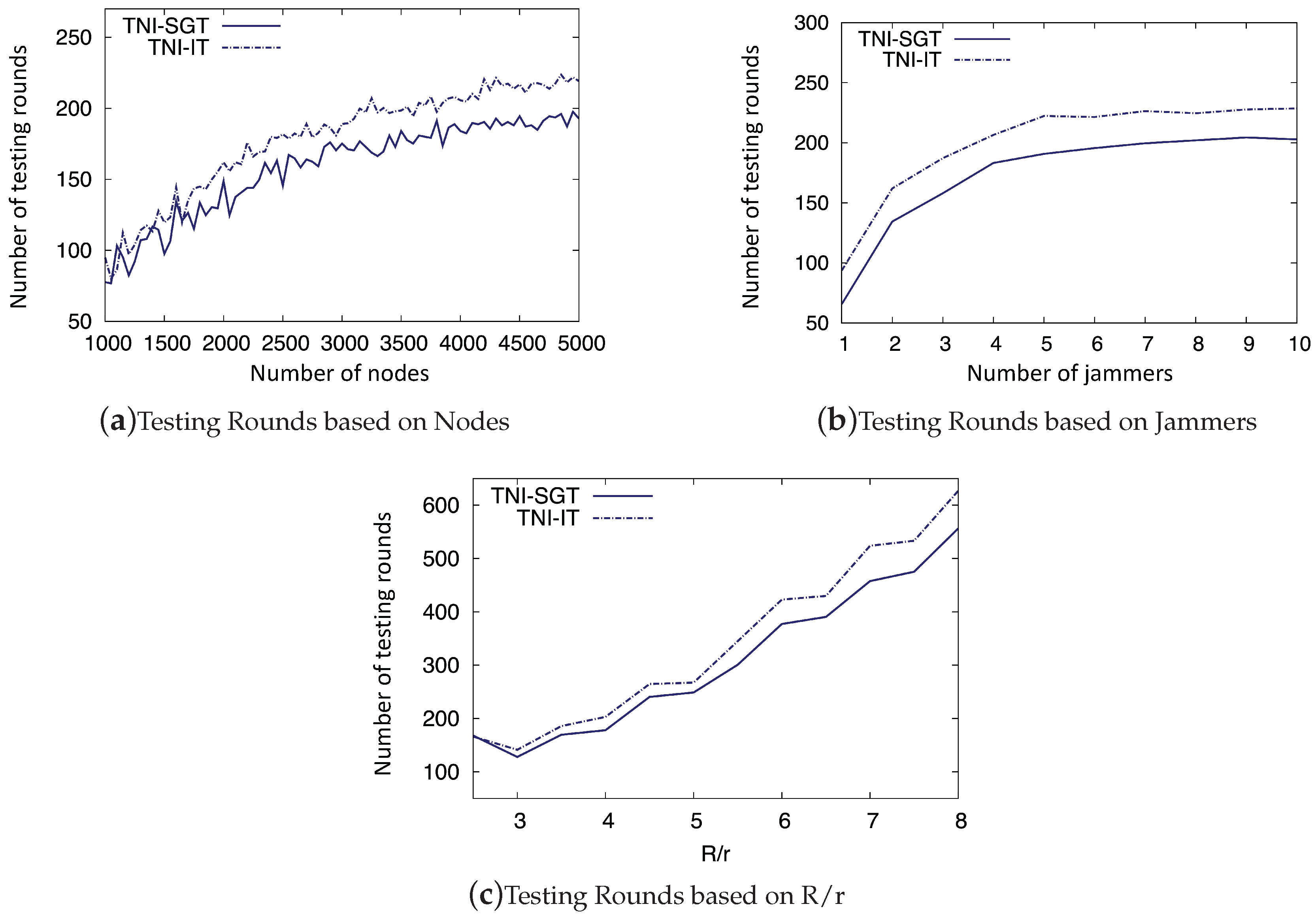
7.1.1. Testing Rounds T
The round of group testing is averaged from the network configuration with a varying number of wireless devices in Figure 5a, which indicates the computational latency of TNI-SGT algorithms by the predefined duration of a testing round. As depicted in Figure 5a, the testing rounds for the completion on the identification of all trigger nodes gradually ascend, compared to the incremental size of nodes in denser networks. In the duration of the devices in increments from 1000 until 5000, while the number of testing rounds grow steadily by approximately 120 additional rounds in TNI-SGT, TNI-IT tests require at most 50 more rounds for the identification of all triggers. The observations can be explained as follows: sequential GT with Quick Identification and Quick Elimination method detects all trigger nodes efficiently due to the fact that more nodes require to be tested with more rounds, as the density of networks increases with additional devices. Furthermore, the design of TNI-SGT algorithm for the identification of all trigger devices only on the convex hull of every hexagon provides a great benefit over the latency of the time complexity.
The performance of TNI algorithms from different numbers of the reactive jamming devices is addressed via Figure 5b so as to provide the efficiency of the localized countermeasure scheme in the case of massive number of jammers in the Smart Grid wireless mesh networks. Because and with are sufficient parameters to analyze the performance with a massive number of jammers over in Smart Grid wireless mesh networks, no more jammers over are investigated. As the number of jammers swells up to 10 times the initial count, just 130 additional testing rounds are required from with around 70 initial tests to in TNI-SGT. Consequently, even with massive impact scenario against the wireless mesh networks from more jammers, the localized algorithm on the identification of trigger devices supports the feasibility on practical Smart Grid wireless mesh networks with great robustness.
Finally, the testing rounds shows diversity due to the distance among interference-free testing groups according to the size of , while parameter value bigger than 8 would be impractically scenarios. As indicated by Algorithm 2, disjoint interference-free testing groups have to be far away at least , therefore the distance between parallel testing groups is tightly related to the number of colors. Due to the fact that bigger results in more colors with smaller number of interference-free testing groups, Figure 5c discloses increasing trends of tests in both TNI algorithms.
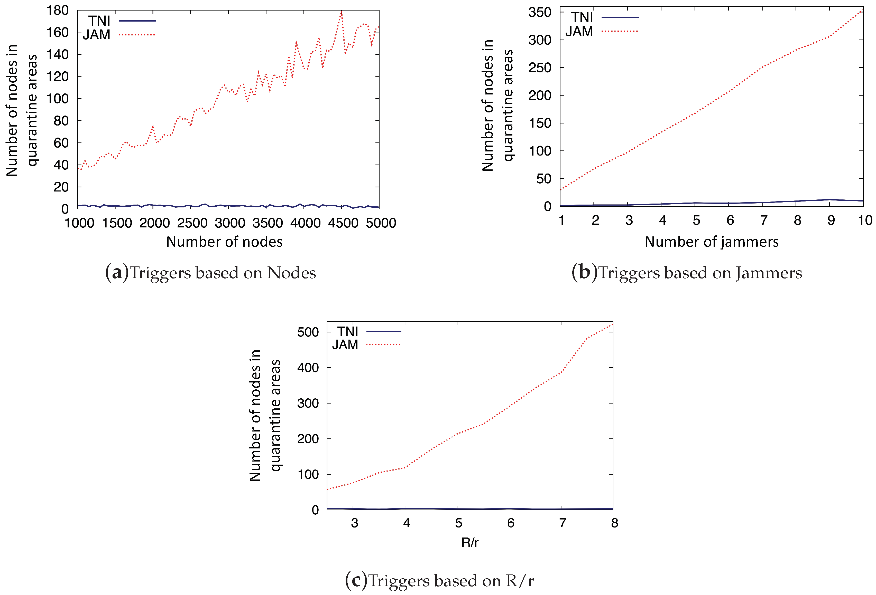
7.1.2. The Number of Nodes in Quarantine Areas
After the construction of a jamming-resistant message delivery path by shifting all the identified trigger devices to receivers only, it would be possible for them to be unreachable triggers which are located too deep to receive messages in the case that a trigger would be not able to communicate with others but with triggers only. The number of unreachable trigger devices in the network is to be compared with the volume of jammed devices from JAM algorithm, which is helpful to determine the actual size of quarantine regions out of wireless communication. This is because not only the unreachable triggers in our approach but also the jammed devices in the JAM scheme [12] cannot receive any messages.
In accordance with Figure 6, the volume of unreachable trigger devices is always substantially less than the number of jammed devices from the JAM approach. Especially, in Figure 6a, less than a couple of devices are unreachable triggers and could not receive any wireless messages where , but jammed devices in the JAM scheme get significantly larger within the higher network density.
In Figure 6b, as predicted, the size of unreachable triggers remains small, less or equal to 10 jammers, but the jammed devices sprout with higher population with more jamming devices in the mesh networks.
With a fixed number of jammers and wireless nodes, larger size of results in bigger impact from jammers, which implies more jammed nodes in the JAM algorithm. Yet, importantly, our identification approaches will not get affected by in terms of unreachable trigger nodes. That is, by utilizing the successful identification of all trigger nodes, actual jammed areas in which no node would be able to send out any messages to avoid a reactive jamming signal would be very small, so that substantially more devices would be participating in unsecured communications than in the JAM approach.
8. Conclusions and Further Discussion
In this paper, we introduce a novel localized countermeasure to effectively tackle the reactive jamming threat to the Smart Grid wireless mesh networks by the identification of trigger devices. Our localized approach for the identification of all triggers accomplishes high implementable feasibility with low computational overhead in terms of message complexity and latency in time by the hexagon tiling scheme and the sequential group testing techniques. We design the hexagon tiling coloring algorithm to employ the availability on the spatial parallelism to perform the identification of triggers in the Smart Grid wireless mesh networks by reducing the overall latency of the group testing. In accordance with the assignment of colors on each hexagon, all testing groups within the same color are scheduled to perform the localized identification of trigger devices simultaneously using the sequential GT manner. Besides the analytic proof on the run-time and message complexities, an intensive set of experimental simulations has supported an outstanding performance of our security method on the various configuration of the Smart Grid wireless mesh networks in terms of scalability and stability.
In the case that jammer randomly reacts with probability p, the group testing results would be incorrect in identifying the triggers. As a future work, we will propose a more accurate identification algorithm against the random reactive jamming model.
Author Contributions
Conceptualization, I.S. and M.C.; Methodology, I.S.; Writing; I.S. and M.C.
Funding
This research was supported by Basic Science Research Program through the National Research Foundation of Korea(NRF) funded by the Ministry of Science, ICT & Future Planning(2017R1C1B5018413) and 2018 Research Fund of Myongji University.
Conflicts of Interest
The authors declare no conflict of interest.
References
- Wang, W.; Xu, Y.; Khanna, M. A Survey on the Communication Architectures in Smart Grid. Comput. Netw. 2011, 55, 3604–3629. [Google Scholar] [CrossRef]
- He, H.; Yan, J. Cyber-Physical Attacks and Defences in the Smart Grid: A Survey. IET Cyber-Phys. Syst. Theory Appl. 2016, 1, 13–27. [Google Scholar] [CrossRef]
- Janke, R.; Tryby, M.; Clark, R.M. Industrial Control System (ICS) Cyber Security for Water and Wastewater Systems. In Protecting Water Supply Critical Infrastructure: An Overview; Springer: Cham, Switzerland, 2014; pp. 87–105. ISBN 978-3-319-01091-5. [Google Scholar]
- Bellardo, J.; Savage, S. 802.11 Denail-of-Service Attacks: Real Vulnerabilities and Practical Solutions. In Proceedings of the 12th Conference on USENIX Security Symposium, Washington, DC, USA, 4–8 August 2003. [Google Scholar]
- Ling, Q.; Ren, J.; Li, T. Message-Driven Frequency Hopping—Design and Analysis. In Proceedings of the Third International Conference on Wireless Algorithms, Systems, and Applications (WASA ’08:), Dallas, TX, USA, 26–28 October 2008; pp. 373–384. [Google Scholar] [CrossRef]
- Sidek, O.; Yahya, A. Reed Solomon Coding for Frequency Hopping Spread Spectrum in Jamming. Environment. Am. J. Appl. Sci. 2008, 5, 1281–1284. [Google Scholar] [CrossRef]
- Strasser, M.; Popper, C.; Capkun, S. Jamming-resistant Key Establishment using Uncoordinated Frequency Hopping. In Proceedings of the 2008 IEEE Symposium on Security and Privacy, Oakland, CA, USA, 18–21 May 2008; ISBN 978-0-7695-3168-7. [Google Scholar]
- Chiang, J.T.; Hu, Y.-C. Dynamic Jamming Mitigation for Wireless Broadcast Network. In Proceedings of the IEEE INFOCOM 2008—The 27th Conference on Computer Communications, Phoenix, AZ, USA, 13–18 April 2008. [Google Scholar] [CrossRef]
- Desmedt, Y.; Safavi-Naini, R.; Wang, H. Broadcast Anti-Jamming Systems. In Proceedings of the IEEE International Conference on Networks (ICON ’99), Brisbane, Queensland, Australia, 28 September–1 October 1999; ISBN 0-7695-0243-1. [Google Scholar]
- Xu, W.; Wood, T.; Trappe, W.; Zhang, Y. Channel Surfing and Spatial Retreats: Defenses against Wireless Denial of Service. In Proceedings of the 3rd ACM Workshop on Wireless Security, Philadelphia, PA, USA, 1 October 2004; pp. 80–89, ISBN 1-58113-925-X. [Google Scholar]
- Xu, W.; Trappe, W.; Zhang, Y. Channel Surfing: Defending Wireless Sensor Networks from Interference. In Proceedings of the 2007 6th International Symposium on Information Processing in Sensor Networks, Cambridge, MA, USA, 25–27 April 2007; pp. 499–508, ISBN 978-1-59593-638-7. [Google Scholar]
- Wood, A.D.; Stankovic, J.A.; Son, S.H. JAM: A jammed-area mapping service for sensor networks. In Proceedings of the 24th IEEE Real-Time Systems Symposium (RTSS 2003), Cancun, Mexico, 5 December 2003; ISBN 0-7695-2044-8. [Google Scholar]
- Shin, I.; Shen, Y.; Xuan, Y.; Thai, M.T.; Znati, T. Reactive Jamming Attacks in Multi-Radio Wireless Sensor Networks: An Efficient Mitigating Measure by Identifying Trigger Nodes. In Proceedings of the 2nd ACM International Workshop on Foundations of Wireless Ad-Hoc and Sensor Networking and Computing (FOWANC ’09), New Orleans, LA, USA, 18 May 2009; pp. 87–96, ISBN 978-1-60558-523-9. [Google Scholar]
- Xuan, Y.; Shen, Y.; Shin, I.; Thai, M.T. On Trigger Detection against Reactive Jamming Attacks: A Clique-Independent Set based Approach. IEEE Trans. Parallel Distrib. Syst. 2012, 23, 223–230. [Google Scholar]
- Fang, S.; Liu, Y.; Ning, P. Wireless Communications under Broadband Reactive Jamming Attacks. IEEE Trans. Dependable Secure Comput. 2016, 13, 394–408. [Google Scholar] [CrossRef]
- Tague, P.; Slater, D.; Poovendran, R. Linear Programming Models for Jamming Attacks on Network Traffic Flows. In Proceedings of the 2008 6th International Symposium on Modeling and Optimization in Mobile, Ad Hoc, and Wireless Networks and Workshops, Berlin, Germany, 1–3 April 2008; pp. 87–96. [Google Scholar] [CrossRef]
- Huynh, P.H.; Chow, C.E. Design and Analysis of Hybrid Wireless Mesh Networks for Smart Grids. Adv. Intell. Syst. Appl. 2013, 1, 713–721. [Google Scholar]
- Xu, W.; Trappe, W.; Zhang, Y.; Wood, T. The Feasibility of Launching and Detecting Jamming Attacks in Wireless Networks. In Proceedings of the International Symposium on Mobile Ad Hoc Networking and Computing, Urbana-Champaign, IL, USA, 25–27 May 2005; pp. 6–57. [Google Scholar]
- Niculescu, D.; Nath, B. Ad Hoc Positioning System (APS) using AOA. In Proceedings of the Twenty-Second Annual Joint Conference of the IEEE Computer and Communications Societies (INFOCOM 2003), San Francisco, CA, USA, 30 March–3 April 2003. [Google Scholar] [CrossRef]
- Niculescu, D.; Nath, B. Ad Hoc Positioning System (APS). In Proceedings of the IEEE Global Telecommunications Conference (GLOBECOM’01), San Antonio, TX, USA, 25–29 November 2001. [Google Scholar] [CrossRef]
Figure 1.
Reactive Jamming Attack and Mitigation by Identification of the Triggers.

Figure 2.
The Minimum Distance Between Two Nodes with Same Color.

Figure 3.
The Coloring Pattern for .

Figure 4.
Trigger Nodes in a Hexagon.

Figure 5.
Rounds by Various Parameters.

Figure 6.
Nodes in Quarantine Areas by Various Parameters.

© 2018 by the authors. Licensee MDPI, Basel, Switzerland. This article is an open access article distributed under the terms and conditions of the Creative Commons Attribution (CC BY) license (http://creativecommons.org/licenses/by/4.0/).
Share and Cite
MDPI and ACS Style
Shin, I.; Cho, M. On Localized Countermeasure Against Reactive Jamming Attacks in Smart Grid Wireless Mesh Networks. Appl. Sci. 2018, 8, 2340. https://doi.org/10.3390/app8122340
AMA Style
Shin I, Cho M. On Localized Countermeasure Against Reactive Jamming Attacks in Smart Grid Wireless Mesh Networks. Applied Sciences. 2018; 8(12):2340. https://doi.org/10.3390/app8122340
Chicago/Turabian StyleShin, Incheol, and Minkyoung Cho. 2018. "On Localized Countermeasure Against Reactive Jamming Attacks in Smart Grid Wireless Mesh Networks" Applied Sciences 8, no. 12: 2340. https://doi.org/10.3390/app8122340
Note that from the first issue of 2016, this journal uses article numbers instead of page numbers. See further details here.