Continuum Damage-Healing and Super Healing Mechanics in Brittle Materials: A State-of-the-Art Review

1
Institute of Structural Mechanics (ISM), Bauhaus-Universität Weimar, Marienstraße 15, D-99423 Weimar, Germany
2
Teknik Sipil, Politeknik Negeri Bandung, Gegerkalong Hilir Ds.Ciwaruga, Bandung 40012, Indonesia
*
Author to whom correspondence should be addressed.
Appl. Sci. 2018, 8(12), 2350; https://doi.org/10.3390/app8122350
Submission received: 21 October 2018
/
Revised: 12 November 2018
/
Accepted: 13 November 2018
/
Published: 22 November 2018
(This article belongs to the Special Issue Computational Methods for Fracture)
Abstract
:Over the last several years, self-healing materials have become more and more popular in terms of damage reparation. Moreover, a recent theoretical investigation of super healing materials that aims at repairing and strengthening itself was also developed. This research area is well known by the rich experimental studies compared to the numerical investigations. This paper provides a review of the literature of continuum damage-healing and super healing mechanics of brittle materials based on continuum damage and healing mechanics. This review includes various damage-healing models, methodologies, hypotheses and advances in continuum damage and healing mechanics. The anisotropic formulations of damage and healing mechanics are also highlighted. The objective of this paper is also to review the super healing theory based on continuum damage-healing mechanics and its role in material and structure strengthening. Finally, a conclusion of the reviewed damage-healing models is pointed out and future perspectives are given.
1. Introduction
Brittle materials are subjected to microstructural degradations that lead to their failure. The material degradation is the result of the nucleation and growth of microvoids and microcracks. This phenomenon is expressed and termed by damage. In recent years, self healing materials have been used to repair damage in materials. Therefore, many investigations are conducted on self-healing materials. French Academy of Science discovered the self-healing theory in 1836. They found that calcium carbonate results from cement hydration on exposure to atmosphere that concerns the autogenous self-healing mechanism [1,2]. This is due to hydration of cement or carbonation of calcium hydroxide [3]. The second category, called autonomous self-healing, was first proposed in [4]. The self-healing concept aims at automatically repairing the damages occurring in the material. Inspired from this idea, Barbero et al. [5] developed the continuum damage-healing mechanics (CDHM) for composited materials. CDHM represents the extension of the continuum damage mechanics (CDM) in which the healing effect is introduced into the constitutive equations. Furthermore, many investigations based on fracture mechanics and advanced finite element methods such as discrete particle/element method [6] and smooth particle hydrodynamics (SPH) [7] were also carried out on self-healing materials. For more details on these methods, the reader can refer to Refs. [8,9,10,11,12,13] for the discrete particle/element method, Refs. [14,15,16,17] for the SPH method, Refs. [18,19,20,21,22,23,24] for meshfree method, [25,26,27,28,29,30] for the multiscale method, Refs. [31,32,33,34,35] for the phase field method, and Refs. [36,37,38,39,40,41,42] for advances in fracture mechanics.
The presentation of CDM was first given by Kachanov [43] in which the continuum damage mechanics framework was originally applied to handle the response of the creep failure of metal alloys. This framework was further developed by Rabotnov [44] in which the damage factor concept was introduced. CDM framework was further extended by many researchers who aimed at describing the process of damage [45,46] where it was assumed that the material starts to rupture once the damage variable reaches a critical level. At the beginning of the application of CDM, much attention was given to the analysis of damage due to creep [47,48,49,50]. Later on, further developments were carried out using the principles of continuum damage mechanics [51,52,53,54,55,56,57,58,59,60,61,62,63,64,65,66]. In general, damage mechanics interests in the study of the material in different scales, namely, microscopic, mesoscopic, macroscopic, and mixed scale (statistical method), in which the damage models are applied to describe the variation of the material properties and material failure due to crack initiation and propagation. The basic issue of CDM is to quantify the damage in the material. Many researchers defined the damage variable as the ratio of the number of damaged and total cross-section [67,68], while other researchers used the concept of the effective stress to define the damage variable [69,70]. Another method used to calculate the damage variable which is based on the elastic stiffness reduction was also proposed by Lemaitre [71], and investigated further by many researchers [72,73]. The damage variable can be expressed as a scalar variable in the case of isotropic material and as a tensor in the case of anisotropic material [74,75].
The description of the quasi-static behavior of ductile and brittle materials came subsequently on [76,77,78,79,80]. Application of conventional local damage models results in ill-posedness problems and strain localization due to the softening behavior of brittle materials which can be avoided using particular a simulation. This simulation can be performed using the developed nonlocal damage models of integral and gradient types [81,82,83]. A large range of applicability of the nonlocal theories can be found in literature, which can simulate the crack initiation and propagation based on continuum mechanics. The nonlocal damage models raised some limitations which are still not completely resolved [84,85]. The characteristic length is a parameter intrinsic to the material whose characterization as well as the physical sense strongly depends on the material model chosen. Whatever the non-local method chosen, it enriches the description of the classical continuum mechanics.
Comparing to the investigations that carried out on continuum damage mechanics, the focus on the continuum damage healing mechanics is still in its infancy. In the present work, an overview of continuum damage-healing and super healing mechanics and their applicability is provided. Review of different aspects of damage and healing measures based on cross-sectional area and elastic stiffness reduction is given. Afterwards, advances of damage-healing models applied on brittle materials are discussed. The anisotropic formulation of damage and healing and some advances are also reviewed. Finally, the super healing theory that aims at strengthening of materials and structures is given and discussed in detail.
2. Damage and Healing Configurations
In this section, review of damage and healing variables is presented based on CDHM. According to CDM, the undamaged, damaged and effective material states defined by the undamaged cross-section , damaged cross-section and effective cross-section are respectively illustrated in Figure 1. The initial, damaged and effective configurations are also represented by their elastic modulus , and , respectively. The damage variable can mostly be defined based on either cross-sectional or elastic stiffness reduction. The expressions of the damage variable based on cross-sectional reduction and elastic stiffness reduction are expressed as follows [86]:
where is the damage variable and it takes the value when the material is undamaged and the value when the material is totally damaged. In [87], the authors defined the damage variable based on shear modulus G, Poisson’s ratio and the bulk modulus K reduction respectively as follows:
where , and are, respectively, the effective shear modulus, effective Poisson’s ratio and the effective bulk modulus. As the damage is well-known to reduce the cross-section and material stiffness, the healing takes an opposite role of the recovering of the cross-section and material stiffness (see Figure 2). Then, the healing variable can be defined respectively as a function of the cross-section and material stiffness recovery follows [86]:
where h, and represent the healing variable, healed cross-section and elastic stiffness, respectively. The values of h = 0, 0 < h < 1, and h = 1 represent the unhealed, partially healed, and fully healed material states, respectively. In [88], the authors defined two healing variables that reflect the healing effect in the case of coupled and uncoupled self-healing mechanics. The former mechanism assumes that the healing and damage occur simultaneously, while the latter one assumes that the healing is introduced when damage is constant (more details are given in Section 3.6). The expression of the healing variable in the case of coupled self-healing mechanism () is similar to Equation (7), while, for the uncoupled self-healing mechanism (), it is written as follows [88]:
When damages are removed from (Figure 1c), the relationship between the nominal stress and effective stress becomes as follows [43,66,76]:
According to CDHM and following the configurations in Figure 2, Equation (9) becomes in the case of self-healing materials as follows [88,90]:
Another relation of the nominal stress and effective stress was proposed in [91]. The authors assume that the material is totally healed when h = 0 and it is totally damaged when h = 1. This proposition takes the following expression:
It is clear from Equation (10) that the effective stress is equal to the nominal stress when the material is fully healed (h = 1 & ), while it approaches infinity when the material is totally damaged (h= 0 & ).
3. Damage-Healing Formulations
In this section, review of proposed formulations of healing laws applied on brittle materials are discussed. Some of them are not based on CDHM, but they are highlighted in this section in order to provide the reader an overall idea of mathematical, mechanical and phenomenological propositions of healing laws. Next, the damage-healing models that have been developed since 2005 and applied on different materials based on CDHM are also reviewed. The main differences and limitations between these models are also discussed.
3.1. Healing Model Based on Parameter Recovery
A theory of crack healing of polymers was developed by Wool and O’Connor [92] based on a recovery parameter R which is defined as a convolution product. According to this theory, the healing is defined in terms of five stages of healing: (a) surface rearrangement, (b) surface approach, (c) wetting, (d) diffusion and (e) randomization (Figure 3). Different mechanical properties of the material were considered in the intact state of the material such as fracture stress , strain at failure , tensile modulus and fracture energy when the healing history is subjected. The healing history was measured such that the five stages of healing occur simultaneously and the mechanical properties of the material represent the sum of wetting and diffusion process initiated at different times. Based on this assumption, the healing variable was defined as follows:
where is the intrinsic healing function, is the wetting diffusion function and is the nucleation time and represents the running variable of the time axis. The intrinsic healing function was related to the wetting and diffusion for the measure of recovery based on stress or energy consideration. The wetting is obtained when two free surfaces touch each other in which the time is controlled by self-diffusion of the overlapping free surfaces. The diffusion is controlled by the stage of surface rearrangement. When the material is damaged and the cracks appear, the molecular ends start to be able to move on the surface following the wetting stage. When two surfaces start to come into contact, their diffusion across the interface results in the healing and recovery of part of the initial strength. Two cases of wetting diffusion function are considered, namely instant wetting and constant rate wetting. In the case of instant wetting, the two surfaces wet instantaneously at time t = 0 and the wetting diffusion function is expressed as follows:
where is the Dirac-delta function. Consequently, the healing variable in Equation (12) and the intrinsic healing function become similar, as follows:
where K and are the material constant and the fracture strength of the intact material, respectively. On the other hand, in the case of constant rate wetting, the wetting diffusion function is written as:
where and U(t) are the wetting rate and the Heaviside step function, respectively. Thus, the healing variable is expressed as follows:
According to Equations (14) and (16), it is observed that the wetting components of the healing variable is time-independent in the case of instant wetting, while it is time-dependent in the case of constant wetting rate. In addition, it is concluded that Equations (14) and (16) are defined based on empirical assumption using large number of material parameters. Figure 4 shows the plot with respect to the crack healing.
3.2. Fracture Mechanics Based Healing Model
A crack closing model applied on linear and isotropic viscoelastic materials was developed by Schapery [93]. Time-dependent constitutive equations based on continuum mechanics were proposed in which the crack length and contact size are predicted, and the whole healing process is considered. The crack healing model was based on crack area reduction , which is related to the Poisson’s ratio, fracture process zone, effective bond energy and the tensile bond force. is expressed as follows:
where , , , and are the effective bond energy, elastic modulus, tensile bond force, Poisson’s ratio and mode I stress intensity factor. , , and m are material constants. The crack closing model is known by the fact that there is no difference between the crack closing based on wetting and on diffusion. Moreover, the model is formulated based on different materials that make it difficult to be realized in the case of anisotropic material.
Based on the healing variable proposed in [92] and the crack area reduction in Equation (17) [93], a new formulation was proposed in [94,95] in which they used the variable R to simulate the healing effect in bituminous materials as follows:
where , and are the work of cohesion, the healing process zone and material constant, respectively. The rest of the parameters are defined previously in Equation (17). It should be noted that the parameters related to the proposed Equation (18) are difficult to be identified due to the lack of enough experimental data.
3.3. Creep Damage-Healing Model for Salt Rock
Rock salt is generally subjected to creep damage and cracks that result in the increase of the permeability of the material. Because damage results in inelastic flow in rock salt under hydrostatic compression, an extension of continuum damage approach to the healing of creep damage was developed in [96]. It was assumed that the macroscopic strain rate is influenced by the healing mechanism along with damage and creep. Anisotropic healing was also considered such that the conjugate stress measure for healing can be expressed as
where , and are the first invariant of the Cauchy stress, material constant and the maximum principal stress, respectively. It is considered that the healing is isotropic when and anisotropic when . The kinetic equations of the healing were formulated based on an experimental observation that suggests two healing mechanisms can be activated in (Waste Isolation Pilot Plant) WIPP salt. The first mechanism assumes that the healing is present in a much smaller time period which results in unchanged damage variable, while the second mechanism assumes that the healing is present in a larger time period which reduces the damage variable. The healing variable proposed in [96] is considered to be the first-order kinetic equation expressed as
where , H, , are the damage variable, Heaviside function, time characteristic constant and the shear modulus, respectively. describes the removal of damage. The healing variable defined in Equation (20) is characterized by the fact that only an individual healing mechanism can be simulated. This leads to the difficulty of finite element implementation of the healing model due to the challenging identification of the healing time involving non-relative loading histories. Thus, the starting time and the period of the healing become ambiguous.
A simplified version of the healing model proposed in [96] was further developed in [97]. Instead of defining two separate healing mechanisms, a single healing mechanism based on damage, kinetic equation and equivalent stress was proposed. The simplified healing variable was defined with only one kinetic equation for one healing mechanism in contrast to the previous investigation in which one kinetic equation for each healing mechanism was defined. After modification of the kinetic equation, the following healing variable was obtained:
with
where , and are principal stresses and equivalent stress, respectively. , and are material constants. According to Equation (21), healing can be activated only when . In addition, the healing reduces the volumetric strain to zero. The axial and lateral strains are also recovered under hydrostatic compression. In [98], a thermodynamic framework of CDHM was proposed in which the concept of healing surface and loading-unloading conditions were used. Rate-dependent and rate-independent formulations were also given and applied in the case of isotropic healing. The general thermodynamic framework was applied to study the healing crushed rock salt. The surface-based healing function takes the following expression:
where s, B, and are the Cauchy stress tensor, constrained modulus, surface energy per unit area, and the material positive constant, respectively. and are positive material parameters related to the changes in material parameters and surface area. If the healing surface F < 0, the material is supposed unhealed, while the healing is occurring when F = 0. The simulation of the densification of crushed rock salt revealed that the healing model is able to describe the healing mechanism in terms of Young’s modulus and inelastic strain recovery, even though the formulation was limited to isotropic material behavior.
Further investigations of damage-healing of salt rock were undertaken. Based on the formulation in [97], the authors in [99] proposed an anisotropic damage-healing formulation for the modeling of creep process in salt rock. The healing process was defined with respect to a viscoplastic scalar healing variable, and the healing strain component was used to account for the reduction of the deformation. However, it was assumed that the healing compensates deformation only in the lateral directions. In addition, the crack healing was assumed to result in an instant reduction of deformation in which represents the characteristic time needed to close the cracks of the material subject to salt creep. The simplified healing variable that accounts only for diffusion subject to compressive mean stress was expressed as
where A, p, H and G are the new damage variable, first stress invariant, Heaviside function, and the shear modulus, respectively. For more details of the formulation and application of Equation (24), the reader can refer to [100,101,102,103,104]. Xu et al. [105] implemented an elastoplastic damage healing model of mudstone and defined the healing variable as function of the non-associated dissipation criterion. Unlike the expression of the healing variables defined in Equations (6) and (8), a new healing variable equation is expressed as
where and are the healed and undamaged cross-section areas, respectively. It was assumed that the undamaged cross-section area of the healed cross-section area carries the loads. Following this assumption, the effective stress was expressed as follows:
According to this formulation, the cross-section area of the material is divided into three regions: undamaged , unhealed and healed cross-section areas. The damages in the mudstone cannot be fully healed, which results in the unhealed cross-section area being greater than zero. Therefore, it was assumed for simplicity that the healed cross-section area exhibits similar mechanical behavior to that of the original material. However, the boundary conditions of the healing and damage of Equation (26) was unclear. For further self-healing investigations on geomaterials, the reader can refer to [106,107,108,109,110,111,112,113,114].
3.4. Micro-Damage Healing Models for Asphalt Mixtures
In [115], an elastic-viscoelastic model with healing for asphalt concrete subjected to fatigue loading was proposed. The model was extended from the work presented in [116] in which the pseudo-strain variables are given in [117] and adopted to eliminate the dependency of the stress–strain material behavior to time. The irreversible thermodynamic framework was used to simulate the healing of micro-damage. Growing damage was simulated using uniaxial viscoelastic constitutive equations that are extended to account for the micro-damage healing. Uniaxial tensile tests under cyclic loading were conducted under controlled-strain and controlled-stress models with rest periods. In order to induce damage in the specimens, two stress–strain levels were used in the tests. The rest periods introduced during each test vary from 0.5 to 32 min. The variation of the material stiffness before and after the rest period was studied as a function of the number of cycles (Figure 5). Region I in Figure 5 depicts the reduction of the stiffness due to the damage evolution without a rest period, while region II depicts the reduction of the stiffness due to the damage evolution after rest period. After the introduction of the rest period, it was shown that the stiffness increases from point B to point A due to micro-damage-healing and decreases after damage of the healed material. Based on the experimental results and stiffness variation in regions I and II, the following healing function was proposed:
where represents the healing evolution during the ith rest period and represents the damage evolution after the ith rest period. and are the material function and the normalized damage variable. Several experimental investigations were carried out for the study of the micro-damage healing of asphalt mixtures (e.g., [118,119,120,121,122,123,124]). Although the implemented micro-damage-healing model was able to describe the hysteretic behavior under controlled-strain and controlled-stress modes, the identification of the experimental data to simulate the healing behavior is not an easy task.
Another micro-damage-healing model applied to asphalt mixtures subjected to fatigue loads was proposed in [125]. The damage healing model was extended from the viscoelastic, viscoplastic and viscodamage model. The authors defined a healing variable which is a function of the healing time and history, damage level and temperature. The proposed healing variable takes the following expression:
where is the rate of the healing variable, is the healing viscosity parameter and and are material constants. is a function of temperature and is the parameter that determines the speed of the healing. It is expressed as
where and are the healing viscosity parameter at temperature and the healing-temperature coupling parameter, respectively. According to Equation (29), it was assumed that the healing starts to evolve once the temperature reaches a certain reference level (temperature threshold) and decreases when the temperature is less than the reference level. The model was applied to predict the behavior of creep-recovery tests in compression and in tension. An example of the results of the evolution of the creep strain and the effective damage density as function of time in compression is shown in Figure 6. From Figure 6a, it is shown that the introduction of the healing improves the material behavior compared to the model without healing. On the other hand, one can see from Figure 6b that the effective damage increases during loading and decreases during the rest period, while it remains stable during unloading.
The micro-damage healing law proposed in [125] was further investigated in [90,126,127,128]. In [90], a continuum damage mechanics framework was proposed to simulate the micro-damage-healing of materials subjected to cyclic loading. The hypotheses’ strain, elastic energy and power equivalence were used to relate the strain tensor and tangent stiffness in the damage and healing configurations. The authors worked on the update of the current stress tensors in the damaged and healing configurations. Examples of the uniaxial constant strain and stress rates were applied. The results revealed that the hypotheses of strain equivalence and power equivalences overestimate the elastic strain energy in the healing configuration compared to the one in the damaged configuration. On the other hand, the strain equivalence hypothesis overestimates the expanded power in the healing configuration compared to the one in the damaged configuration, while the elastic energy equivalence hypothesis underestimates the expanded power in the healing configuration compared to the one in the damaged configuration. It should be noted that these results apply to both strain-controlled and stress-controlled uniaxial tests. The same authors used the micro-damage healing model to simulate fatigue damage of asphalt concrete [126]. They also studied the effect of compressive stresses on the crack closure. This phenomenon is called the “unilateral effect’’ and is discussed in more detail in Section 3.7. Based on the formulation presented in [125], a theoretical framework of cohesive zone healing model was proposed in [127] and implemented into a finite element code in [128]. The effect of different parameters such as damage history, healing history and resting time were studies. For further investigations on the visco-damage-healing models, the reader can refer to [129,130,131,132,133].
3.5. Curing-Based Damage Healing Law
In [134], the authors proposed a new phenomenological damage-healing model applied to polymers. The proposed healing variable concerned the autonomous self-healing concept and was associated with the curing mechanism of the healing agent and the catalyst. In a microcapsules-based self-healing concept, the propagated cracks break the microcapsules, which results in the release of the healing agent. This latter fills the crack, reacts with the catalyst and they form a solid material in the crack area (Figure 7). It was assumed in this work that the process of cure leads to the mechanical properties variation and stiffness recovery [135]. The formulation was not limited to the healed material, re-damage of the healed material was also considered. The same equations of healing, damage and effective stress in Equations (1), (6) and (10), respectively, were used. As previously shown in Equation (12) [92], the convolution integral was used to define the healing as follows:
where d(s), are the damage variable during the healing period and the parameter that determines the speed of the healing process, respectively. and t are the initial time of the healing and the healing time, respectively. It was assumed that the damage threshold decreases by the introduction of the healing as it is increased due to damage. Therefore, a damage threshold equation was defined which assumes that the behavior of the fully healed material is similar to the original material and the evolution of the healing variable does not affect the increase of the damage variable at constant deformations. The healing was introduced in three cases. The first one concerns the introduction of the healing during the rest period. When the material is loaded and unloaded, the healing variable evolves during a rest period. Afterwards, the material is reloaded and comparison of the stress–strain response of the healed and original materials is carried out. Figure 8 elucidates the stress–strain response of the healed material when the healing is introduced during different rest periods.
In the second example, the healing is introduced when the material is partially damaged while the assumption of its evolution during a required recovery time is kept. It should be noted that, in this example, the strain is released before the evolution of the healing, which means that damage is constant in this phase. The third example concerns the introduction of the healing during a rest period while the strain is assumed to be constant. For further works on modeling of self-healing polymers and microcapsules-based self-healing, the reader can refer to [137,138,139,140,141].
3.6. Damage-Healing Law for Concrete
In the previous work [88], a continuum damage-healing model for autonomous and autogenous self-healing concrete was proposed. In this model, a time-dependent healing variable representing the opposite of the damage variable was proposed. Isotropic material was considered at macroscale subjected to tensile load. The concept of coupled and uncoupled self-healing mechanism was introduced. The uncoupled self-healing mechanism represents the autogenous self-healing, and the coupled mechanism represents the the autonomous self-healing. In addition, both mechanisms were applied in the case of the so-called nonlinear self-healing theory, and comparison with the linear self-healing theory was performed. The authors in [142] proposed the nonlinear self-healing theory. It concerns the generalized nonlinear and quadratic self-healing theories. It should be noted that the classical (linear) self-healing theory is represented in Equation (10). It is called linear because the equation is linear in h. It was revealed that, in the case of small damage, the linear healing theory is a special case of the nonlinear healing theory. The configuration of the nonlinear healing theory is illustrated in Figure 9. Classical damage variable is used to describe the damaged material state in Figure 9a, while the healing variable h is used to describe the partially healed material state in Figure 9b. According to the nonlinear healing theory, a partial area of damage is subjected to healing as clearly shown in Figure 9b in which the healed area is less than the damaged area . The theory of decomposition of the damage variable was used to obtain the combined healing/damage variable . For more details on the decomposition theory, the reader can refer to [75,143]. It should be noted that the combined healing/damage variable of the classical self-healing theory takes the following expression:
According to the nonlinear self-healing theory, Equation (32) becomes respectively in the case of generalized nonlinear and quadratic self-healing theories as follows:
Equations (33) and (34) represent the expression of the nonlinear healing the generalization of Equation (32) in the case of generalized nonlinear and quadratic self-healing theories, respectively. Following the expressions in Equations (33) and (34), the equations of the effective stress of the generalized nonlinear and quadratic self-healing healing models are respectively expressed as follows:
The damage healing model proposed in [88] was formulated based on the introduction of the healing variable into the damage model. When Mazars damage model for concrete material was adapted, the damage variable was expressed as [143]
where A and are material parameters and is the strain threshold of damage. is the unidirectional strain. It was assumed that the healing is introduced during loading, unloading, and rest period phases; deformed and undeformed material states. The deformed state represents the coupled self-healing mechanism, while the undeformed state represents the uncoupled self-healing mechanism. In the first case, damage and healing evolve simultaneously, and, in the second case, the healing is introduced during unloading or rest periods. In addition, the generalized nonlinear self-healing formulation was applied in the case of coupled self-healing mechanism, and the quadratic self-healing theory was applied in the case of uncoupled self-healing mechanism. The influence of several parameters on the healing efficiency was studied. It concerns the damage history, rest period and material characteristics. The material characteristics were defined mathematically using the parameter . The proposed healing variable was expressed in two cases; uncoupled and coupled self-healing mechanisms as follows:
where , are the uncoupled healing variable, uncoupled healing variable and the material parameter, respectively. is the damage variable during the healing period and represents the critical damage that induces the healing process. is constant after unloading phase . In this model, the healing efficiency is described during loading in which damage and healing evolve simultaneously. In this case, damage evolves until failure. The healing is assumed to start at time and stops at time . The healing period is defined by . The material paramaters influencing the healing efficiency considered in this work were the following:
- History of loading and damage;
- Rest period;
- Material characteristics that were reflected mathematically in this present work represented by the parameter .
Figure 10 shows the stress–time response of the damage healing model in the case of uncoupled self-healing mechanism according to the classical self-healing theory. It is clear that the stiffness recovery is partially recovered for a short period of healing, while it is fully recovered with 30,000 s of rest period. Figure 11 shows the stress–time response of the model in the case of coupled self-healing mechanism. In this example, different values of the material parameter were considered. It is shown that small value of the parameter results in partial stiffness recovery of the material, and results in complete stiffness recovery. The coupled and uncoupled self-healing mechanisms were also applied using the nonlinear self-healing theory. It was found that the healing efficiency is underestimated using both coupled and uncoupled nonlinear self-healing compared to the linear self-healing theory. Further investigations on self-healing concrete and cementitious materials can be found in [144,145,146,147,148,149,150].
3.7. Unilateral-Effects-Based Models
Damage material weakens the mechanical properties of the material. These properties can be recovered if the cracks close again. When the material is subjected to tensile loads and followed by compressive loads in the same direction, the cracks close in the compression domain and the material recovers its stiffness. This is known by the unilateral effects. The unilateral effect is simulated with the distinguishment between damage in tension and damage in compression using two damage variables. Using damage variable in tension and damage variable in compression, the loading mode for a diffuse network of identical microcracks is defined. The unilateral effect can be classified as a healing process due to its effect of crack closure. Many authors pointed out that taking into account the unilateral effect often leads to ambiguity in the computational analysis [151,152]. In [153], the authors developed an isotropic 3D damage model for quasi-brittle materials that accounts for the microcracks closure. An anisotropic continuum damage framework accounting for the unilateral effect was proposed in [154]. In [155], the crack closure was simulated through the decomposition of the stress and strain tensors into positive and negative projection operators. Zhu and Arson [156] proposed a thermodynamic framework to study the effect of the mechanical stress and temperature on the crack opening and closing in rocks, and crack closure was simulated through unilateral effect. The authors in [157] proposed a micro-macro chemo-mechanical damage-healing model to simulate the evolution of the salt stiffness due to microcracks opening, closing and propagation. A unilateral effect was taken into account to simulate the crack closure and stiffness recovery under compression. The proposed model was found to be able to predict the stiffness recovery by the unilateral effect of crack closure. In [158], a nonlocal formulation of concrete damage model with unilateral effects. Unlike the use of spectral decomposition of stress or strain, the unilateral effect was simulated using the trace of the strain tensor. Matallah and La Borderie [159] developed an inelastic-damage model that simulates the crack opening due to inelasticity and elastic modulus recovery due to crack closure. The crack closure was described using a scalar damage variable that is coupled with the Unitary Crack Opening (UCO). UCO is the internal variable that describes the inelastic strain. A function S called Cracks Opening Indicator was introduced in order to control the vanishing of the inelastic strain effect in the material when it is loaded under compression. It was assumed that the function S takes the value zero when the cracks are completely closed and takes the value of 1 when the cracks are completely opened. The expression of the function S was defined as
where is the actual tension yield function value and is the tension yield function value corresponding to the crack closure stress . It was also assumed that the material recovers its initial stiffness when . It should be noted that the proposed model was not able to simulate complex problems that occur during complex unloading phase because the function S represents a scalar variable.
4. Anisotropic Damage-Healing Formulations
Damage and healing of brittle materials are generally simulated by conventional continuum damage-healing mechanics in which scalar damage and healing variables are used to describe the relationship between nominal stress and effective stress; isotropic damage models. In addition, anisotropic damage-healing formulations were also recently proposed and studied using second-order and fourth-order damage and healing tensors. Murakami [160] was the first who generalized the multi-axial anisotropic formulation of the description of the material degradation. Although most of the works conducted on CDHM are based on isotropic presentation, an anisotropic CDHM was also investigated by the introduction of a healing tensor. According to the formulation [161], the damage variable tensor is expressed as
where and are the damage and effective fictitious area vectors, respectively. When the healing is introduced into the material, the effective area increases. Figure 12 shows the anisotropic damage and healing configurations [161]. According to the presentation in Figure 12, the authors in [161] proposed a second rank anisotropic healing variable tensor as follows:
where describes the relationship between the damaged area vector and the effective healed area vector. In the same paper, is denoted the fourth-order anisotropic damage variable tensor and describes the elastic modulus degradation as follows:
where and are the undamaged and damaged elastic tensors. The subscripts in Equation (43) represent the two different mathematical tensorial expressions of the damage tensor. In addition, a new fourth rank healing tensor was also defined to measure the elastic modulus recovery as follows:
where is the healed elastic modulus. It was assumed that the material is undamaged when is the fourth rank zero tensor) and is fully healed when .
The generalization of the relational between the effective stress and nominal stress of Equation (9) is expressed in the case of anisotropic materials as follows [64,74]:
where represents the fourth-rank damage effect tensor. and are the effective and Cauchy stress tensors, respectively. The relationship between M and was investigated in the literature [66,87,162] and expressed as
In the case of anisotropic damage-healing mechanics, Equations (35) and (36) become
where is the fourth-rank identity tensor and H is the fourth-rank healing tensor. This equation was obtained by assuming that the tensor H corresponds to 1/h [66,87,162]. Based on CDHM, it can be observed from Equation (47) that the parameter is generalized to become .
The proposed healing tensor was later decomposed to healing tensor for cracks and healing tensor for voids in [163] along the lines of the decomposition theory applied on scalar based healing definition in [73,163]. For more details on the definition of the anisotropic damage variable tensors that were defined based on cross-section area reduction and elastic stiffness degradation, the reader can refer to [75,143]. The same authors proposed an anisotropic presentation of new damage variables that are called Fabric Tensors [74,87,162]. Later on, the same authors of [161] extended their work and proposed a coupled viscoplastic-viscodamage-viscohealing model to study the irregular behavior of glassy polymers [129]. Power function was added to the Frederick–Armstong–Philips–Chaboche (FAPC) model in the expression of the dynamic recovery of the hardening function. This latter results in increase of back stress evolution that cannot describe the irregular responses associated with the inelastic responses of glassy polymers. A thermodynamic viscoplastic-viscodamage-viscohealing framework was presented where the healing was assumed to be coupled or uncoupled. The same coupled and uncoupled healing systems were investigated previously using a thermodynamic framework of elasto-plastic-damage-healing problems [164].
Asphalt concrete is a multiphased material and exhibits complicated mechanical behavior and multiple modes of degradation. In [165], the authors developed a viscoelastic-viscoplastic model coupled to anisotropic damage in which a second-order tensor damage tensor was introduced in order to relate the nominal and effective stresses. The damage tensor was divided into permanent and non-permanent parts. The first part represents the classical damage process, while the second part represents the self-healing during unloading and rest period. A creep recovery test was simulated using the healing model. The rest concerns the application of a pressure of 1 MPa during 800 s. Afterwards, unloading period of 50 s and rest period of 3000 s were imposed. A reduction of the degradation was observed during the unloading and rest period (Figure 13). Some investigations were also carried out in which anisotropic damage is coupled with a scalar healing variable. In this regard, the authors in [99,156] developed a thermodynamic damage healing model applied to salt rock with alternative fabric descriptors. Later on, the anisotropy induced by the healing was also modeled in [103]. The effect of crack opening, closure and healing on the stiffness evolution was described by means of a multiscale model. Fabric tensors are used to relate the microcrack evolution with the macroscopic deformation rate. In [25,145], the anisotropic Cosserat continuum model was used to simulate the damage, healing and plastic of granular materials. Combination of damage and healing was defined in terms of undamaged and damaged elastic moduli tensors. Other investigations on the anisotropic definition of damage variable based on elastic modulus tensor degradation were undertaken. This concerns the decomposition of the stiffness [73], definition of anisotropic damage tensors based on Poisson’s ratio, shear modulus and bulk modulus degradation [87], and description of damage in series and damage in parallel [166].
5. Super Healing Theory
Recent research investigation reveals that self-healing presents a crucial solution for the strengthening of the materials. This solution is termed as Super Healing. Super healing theory was first proposed in [167]. Once the stiffness of the material is recovered due to self-healing, further healing can result as a strengthening material. In this section, we present the theory of the super healing model within the framework of continuum damage mechanics.
The super healing process comes into play after complete healing of the material (h = 1) in which the healing mechanism continues beyond its limit h = 1. After this limit, the strengthening and enhancing of the material properties takes place instead of healing, and the material will be able to heal and strengthen itself. A refined theory of super healing was proposed in [89]. According to the theory, the same healing material is assumed to be used as super healing material (Figure 14). In this case, the value of the healing variable can increase beyond what is necessary to recover the initial stiffness of material.
From Equation (10) of the self-healing theory, it can be observed that, when the material is fully healed, the healing variable h takes the value of 1. In the theory of super healing, once the material recovers its initial stiffness the healing is supposed to be continued . In this case, the healing will act as a strengthening material. In Figure 13, the super healing configuration is illustrated. The super healed material is characterized by its higher elastic modulus which is higher than the elastic modulus of the healed and original material . In Figure 15, the variation of the elastic modulus of the material in different configurations is illustrated. The material is undamaged in the initial state and its stiffness is represented by the initial elastic modulus . When the material is subjected to external loading and after the energy exceeds the material threshold, damage accumulates via the variable . In this case, the material is damaged and its stiffness is represented by the elastic modulus , which is inferior to the initial stiffness. The material can be partially or fully healed. Thus, the elastic moduli and represent the stiffness of the partially and fully healed material, respectively. Introducing the super healing material leads to the enhancing and strengthening of the material stiffness in which the elastic modulus of the super-healed/strengthened material is higher than the elastic modulus of the fully healed and original material.
According to the super healing theory, it is supposed that the healing continues beyond its limit after the material recovers its initial stiffness. In this phase, the healing variable will reach large values such as 2, 3, 4, ⋯, x. x represents the maximal value of super healing that can be applied. The super healing theory is categorized into two mechanisms: single and multiple super healing mechanisms. In the first mechanism, the variable is defined by a large value at one single point of the material. This mechanism can be found in reality for example in the case of microcapsules-based self-healing concrete [4,168,169]. In this case, when only one single crack appears in the material and is healed further due to self-healing, the strengthening of this material due to super healing material should take one large single value of that enhances the stiffness of the material in the area of the single crack. In the second mechanism, the value is defined by small values different points of the material. This case can be found for example when the concrete is damaged in different points (multiple cracks) in which the super healing acts with small values of different points. The values of depends in this case on the number of healed cracks. The number of super healing variables is called n. The limitation of the second mechanism is that the variable is able to take only one value that is constant at every point of the material. Unlike the super healing theory proposed in [167], in the refined super healing theory [89], the super healing variable is not restricted to only integer values. It can also take non-integer values. According to the refined super healing theory, the relation of the nominal and effective stresses is expressed as
Equation (49) represents the main result governing the super healing theory. From Equation (49), when the number of super healing parameter n approaches infinity, the effective stress vanishes, which is irrespective of the damage and super healing variables. In addition, when the damage variable , the effective stress retains a finite value. This is explained by the fact that the material will not rupture even though the damage is high. Equation (49) of the super healing theory was also generalized to anisotropic formulation as follows:
where is the fourth-rank super healing tensor corresponding to the super healing variables defined in Equation (49). In addition, examples of one-dimensional and plane stress were applied. It was shown that the proposed super healing theory is applicable in the case of plane stress. Figure 15 shows the effects of the self-healing and super healing mechanisms. From Figure 16b, it is seen that the material enhances its stiffness when the super healing effect is introduced. Generalized nonlinear and quadratic super healing formulation was also presented along the lines of the nonlinear self-healing theory previously presented, and comparison of super healing models was given (Table 1).
Figure 17 shows the comparison of the super healing models. The results revealed that the generalized nonlinear super healing model is the most appropriate to describe the super healing concept. In addition, the link between the proposed theory and the theory of undamageable materials [162,170,171,172] has been studied. It was found that both theories lead to a material that undergoes zero damage during the deformation process. Later on, an investigation of the super healing theory in terms of the elastic stiffness variation was performed in which the hypotheses of elastic strain and elastic energy equivalence were used [86]. Using the hypothesis of elastic strain equivalence, the following expressions of damage, healing and super healing elastic stiffness are respectively expressed as
From Equation (53), it can be seen that, with the healed elastic modulus is greater than the effective elastic modulus , while they become equal when . On the other hand, when , it becomes equal to the damaged elastic modulus. Using the hypothesis of elastic energy equivalence, the following expressions of damage, healing and super healing elastic stiffness are respectively expressed as
Equation (56) of the super healing can represent Equation (55) when the healing is introduced and can represent Equation (54) when the material is only damaged. If the material is undamaged and unhealed, the super healing elastic modulus becomes similar to the initial elastic modulus, while, when the material is fully healed, the super healing modulus becomes similar to the effective elastic modulus. On the other hand, when super healing is introduced, the super healing elastic modulus becomes greater than the effective elastic modulus. Table 2 presents a summary of the elastic moduli, damage, healing and super healing variables in the case of elastic strain equivalence and elastic energy equivalence. It should be noted that R represents the super healing variable ().
6. Self-Healing Metals
In this section, a brief review of different mechanisms of self-healing of ductile materials such as metals is presented. The self-healing concept was widely exploited on polymer, concrete, and ceramic materials; however, few investigations were carried out on self-healing of metals due to the nature of the healing of each material. Metals are known by their high melting temperature, which leads to a challenging process of the healing. There are two mechanisms of self-healing metals: liquid state mechanism and solid state mechanism. The first one is based on adding shape memory alloys (SMA) to the metal matrix that represents a liquid at high temperature. The second one is based on diffusion of solute into the cracks and voids.
6.1. Liquid State Healing Mechanism
The most commonly method for self-healing of metals is the embedding of healing agent into the metal matrix [173]. When the metal is subjected to heating, the matrix becomes liquid, and thus the healing agent becomes able to heal the damage. In addition, damage can be healed in different lifetimes of metals due to the availability of the liquid healing agent. Many investigations were carried out on self-healing mechanisms using SMA [174,175,176]. Figure 18 illustrates the liquid state healing mechanism. When the metal composite is subjected to tensile stress resulting in crack formation, interfacial debonding will occur by crack due to the low strength at the interface of and high strength of SMA. The crack in the metal composite is supposed to heal when the SMA is subjected to high temperature.
Several numerical models were developed to predict the behavior of liquid state healing mechanism. In [177], the authors developed a numerical model to describe the thermomechanical behavior in the interface SMA-matrix. Two-dimensional elasto-plastic model was applied on the matrix and one-dimensional material model was applied on the SMA wires using material subroutine implemented in the software package Abaqus (Version 6.3, 2002, Pawtucket, RI, USA, Hibbitt, Karlsson & Sorensen, Inc., 7.9.3–3). The model shows its ability to describe the behavior of SMA wires at different temperature levels. The authors in [175,176] developed a model that analyzes the relationship between the strength of matrix, stress of SMA wires, and volume fraction of reinforcement. In [178], Zhu et al. developed a three-dimensional model of metal-matrix composites reinforced by SMA. The self-healing mechanism was modelled based on pre-strained SMA wires. In addition, micromechanical approaches were also proposed by many researchers in order to demonstrate the healing efficiency of SMA-based composite structures [179,180,181]. The effectiveness of the description of the microstructure behavior is high. Nonetheless, it is not an easy task to be applied at the specimen level. For more information on the different mechanisms of self-healing metals in fine scale and structural scale, the reader can refer to [182].
6.2. Solid State Healing Mechanism (Precipitation Healing)
This method of healing is based on the minimization of the energy system and decreasing the solubility of the element when the material is subjected to a decreasing temperature. In this case, the alloy changes its phase from liquid to solid upon solidification. The nucleation of precipitation occurs at unstable phases, high energy defect in grain boundaries and free surfaces. Figure 19 illustrates the solute migration along a high diffusion path and precipitation on high energy surfaces. In [183], the authors revealed that aluminium alloys are subjected to healing mechanisms by solute precipitation during creep and fatigue loading. Moreover, in [184], the authors revealed that this mechanism is similar to a precipitation mechanism in powder alloys. Steel material is found to be the material that most demonstrates the efficiency of self-healing cavities. However, creep strength and ductility of the steels can graduate when subjected to high temperatures. In [185,186], it was found that sulfur accelerates creep cavitation. For more information on the healing mechanism of solid state healing, the reader can refer to [173].
Several numerical models were developed to predict the behavior of solid state healing mechanisms. In [187,188,189], molecular dynamic modelings were developed to describe the behavior of solid state healing of microcracks in aluminium and copper. It was shown that dislocation around the microcrack induces healing. In [190], Wei et al. used the same concept to study the crack healing in iron along the lines of the theory applied on aluminium and copper. Based on a finite element method, Huang et al. [191] showed that there are two stages of healing of cracks in the form of ellipsoid subjected to high pressure. The first stage concerns the shrinkage of microcracks and the second one concerns the splitting microcracks. Later on, in [192,193], the authors presented a thermodynamic approach to study the void shrinkage rate considering the void surface, grain boundary and elastic energy. In [194], the impact of high energy electromagnetic field on the elasto-plastic damage material was modelled. The influence of different parameters such as melting and evaporation of metal was considered. The authors in [195] developed a numerical model to describe the creep cavity growth and strain rates in metals through self-healing. It was found that Fe-W alloys represents a good alternative to be used for self-healing at high temperature.
7. Conclusions and Perspectives
A state-of-the-art review of continuum damage-healing and super healing mechanics applied on brittle materials was presented in the present paper. The main features of damage-healing and super healing mechanics considered are as follows:
- The measure and presentation of the healing variable in both autonomous and autogenous self-healing mechanisms.
- The evolution equations of the healing models based on CDHM.
- The influence of different mechanical and environmental parameters on the healing efficiency.
- The effect of the self-healing and super healing on the mechanical behavior of the material.
- The anisotropic presentation of damage-healing and super healing with tensorial formulation.
- The effect of the new strengthening theory based on the super healing and CDHM.
The CDHM represents an extension of the CDM. Based on it, the initial stiffness recovery and enhancing of the mechanical properties of the materials while taking into account many parameters (e.g., microcapsule percentage, temperature, healing time, damage history, … etc.) is described. In addition, two self-healing mechanisms are mechanically studied: autonomous and autogenous. They are also termed respectively by coupled and uncoupled healing mechanisms. Each damage-healing formulation proposed in literature is based on the experimental data of self-healing materials while considering some assumptions for simplicity of the computational analysis (e.g., isotropy of the material instead of anisotropy). This is due to the heterogeneity of the brittle materials. For instance, concrete is an heterogeneous material that has a complex fracture behavior. Taking into account the complexity nature of concrete material in the healing analysis is not an easy task. Moreover, the softening behavior of brittle materials leads to mesh-dependence of their responses due to strain localization when local damage-healing models are used. This issue was thoroughly addressed in CDM using non-conventional damage models (e.g., gradient and nonlocal damage models), while non-conventional damage-healing model is not yet addressed except for a short explanation given in [88].
To the best knowledge of the authors, the healing can regularize the problem of strain localization and mesh-dependency provided damage/healing in the time range it is applied if it is rate-dependent. This regularization happens in the suitable range of time that recovers the original stiffness of the material; minimization and elimination of damage, especially in the case coupled self-healing mechanism in which damage and healing evolve simultaneously. In this case, when one point of material is damaged, the microcapsules (or hollow fibers) are broken and the healing agents are released from the microcapsules. The damage evolves first and the healing agent evolves after it is released, which leads to the deactivation and elimination of the damage evolution. Therefore, it is highly necessary to develop some non-conventional damage-healing models using nonlocal healing variables coupled to local or nonlocal damage variables. In addition, further investigation of anisotropic damage-healing mechanics is needed in which new healing tensors can be proposed. Finally, further studies on the super healing theory will be an interesting task in terms of focusing on some limitations of the theoretical framework (e.g., plasticity, assumption that takes only one constant value at every point of the material). It is hoped that future studies will be carried out in the manufacturing technology along the lines of the super healing theory.
Author Contributions
C.O. conducted the literature review and wrote the paper. L.M.M. contributed in the revision of the paper.
Funding
The first author would like to acknowledge the Deutscher Akademischer Austauschdienst (DAAD) for the financial support of this work. The second author would like to acknowledge the RISTEK-DIKTI (Directorate General of Resources for Science, Technology and Higher Education. Ministry of Research, Technology and Higher Education of Indonesia) under funding agreement No: 153.39/E4.4/2014.
Conflicts of Interest
The authors declare that there is no conflict of interest.
References
- Hilloulin, B.; Grondin, F.; Matallah, M.; Loukili, A. Modelling of autogenous healing in ultra high performance concrete. Cem. Concr. Res. 2014, 61, 64–70. [Google Scholar] [CrossRef]
- Yang, Y.; Lepech, M.D.; Yang, E.H.; Li, V.C. Autogenous healing of engineered cementitious composites under wet–dry cycles. Cem. Concr. Res. 2009, 39, 382–390. [Google Scholar] [CrossRef]
- Giannaros, P.; Kanellopoulos, A.; Al-Tabbaa, A. Sealing of cracks in cement using microencapsulated sodium silicate. Smart Mater. Struct. 2016, 25, 084005. [Google Scholar] [CrossRef]
- White, S.R.; Sottos, N.; Geubelle, P.; Moore, J.; Kessler, M.; Sriram, S.; Brown, E.; Viswanathan, S. Autonomic healing of polymer composites. Nature 2001, 409, 794–797. [Google Scholar] [CrossRef] [PubMed]
- Barbero, E.J.; Greco, F.; Lonetti, P. Continuum damage-healing mechanics with application to self-healing composites. Int. J. Damage Mech. 2005, 14, 51–81. [Google Scholar] [CrossRef]
- Herbst, O.; Luding, S. Modeling particulate self-healing materials and application to uni-axial compression. Int. J. Fract. 2008, 154, 87–103. [Google Scholar] [CrossRef] [Green Version]
- Hall, J.; Qamar, I.; Rendall, T.; Trask, R. A computational model for the flow of resin in self-healing composites. Smart Mater. Struct. 2015, 24, 037002. [Google Scholar] [CrossRef] [Green Version]
- Rabczuk, T.; Belytschko, T. Cracking particles: A simplified meshfree method for arbitrary evolving cracks. Int. J. Numer. Methods Eng. 2004, 61, 2316–2343. [Google Scholar] [CrossRef]
- Rabczuk, T.; Gracie, R.; Song, J.H.; Belytschko, T. Immersed particle method for fluid–structure interaction. Int. J. Numer. Methods Eng. 2010, 81, 48–71. [Google Scholar] [CrossRef]
- Rabczuk, T.; Zi, G.; Bordas, S.; Nguyen-Xuan, H. A simple and robust three-dimensional cracking-particle method without enrichment. Comput. Methods Appl. Mech. Eng. 2010, 199, 2437–2455. [Google Scholar] [CrossRef]
- Zhou, S.; Zhu, H.; Ju, J.W.; Yan, Z.; Chen, Q. Modeling microcapsule-enabled self-healing cementitious composite materials using discrete element method. Int. J. Damage Mech. 2017, 26, 340–357. [Google Scholar] [CrossRef]
- Areias, P.; Rabczuk, T.D.; de Sá, J.C. A novel two-stage discrete crack method based on the screened Poisson equation and local mesh refinement. Comput. Mech. 2016, 58, 1003–1018. [Google Scholar] [CrossRef]
- Gui, Y.L.; Bui, H.H.; Kodikara, J.; Zhang, Q.B.; Zhao, J.; Rabczuk, T. Modelling the dynamic failure of brittle rocks using a hybrid continuum-discrete element method with a mixed-mode cohesive fracture model. Int. J. Impact Eng. 2016, 87, 146–155. [Google Scholar] [CrossRef]
- Rabczuk, T.; Eibl, J. Simulation of high velocity concrete fragmentation using SPH/MLSPH. Int. J. Numer. Methods Eng. 2003, 56, 1421–1444. [Google Scholar] [CrossRef]
- Kalameh, H.A.; Karamali, A.; Anitescu, C.; Rabczuk, T. High velocity impact of metal sphere on thin metallic plate using smooth particle hydrodynamics (SPH) method. Front. Struct. Civ. Eng. 2012, 6, 101–110. [Google Scholar]
- Rabczuk, T.; Xiao, S.P.; Sauer, M. Coupling of mesh-free methods with finite elements: Basic concepts and test results. Commun. Numer. Methods Eng. 2006, 22, 1031–1065. [Google Scholar] [CrossRef]
- Rabczuk, T.; Eibl, J.; Stempniewski, L. Numerical analysis of high speed concrete fragmentation using a meshfree Lagrangian method. Eng. Fract. Mech. 2004, 71, 547–556. [Google Scholar] [CrossRef]
- Triantafyllou, S.P.; Chatzis, M.N. A new damage-healing smooth hysteretic formulation for the modeling of self-healing materials. In Proceedings of the 8th GRACM International Congress on Computational Mechanics, Volos, Greece, 12–15 July 2015. [Google Scholar]
- Rabczuk, T.; Areias, P.; Belytschko, T. A meshfree thin shell method for non-linear dynamic fracture. Int. J. Numer. Methods Eng. 2007, 72, 524–548. [Google Scholar] [CrossRef] [Green Version]
- Rabczuk, T.; Zi, G.; Bordas, S. Enriched Finite Element and Meshfree Methods for Dynamic Crack Propagation Problems. In Proceedings of the 5th Australasian Congress on Applied Mechanics, Brisbane, Australia, 10–12 December 2007; p. 570. [Google Scholar]
- Zi, G.; Rabczuk, T.; Wall, W. Extended meshfree methods without branch enrichment for cohesive cracks. Comput. Mech. 2007, 40, 367–382. [Google Scholar] [CrossRef]
- Rabczuk, T.; Bordas, S.; Zi, G. A three-dimensional meshfree method for continuous multiple-crack initiation, propagation and junction in statics and dynamics. Comput. Mech. 2007, 40, 473–495. [Google Scholar] [CrossRef] [Green Version]
- Rabczuk, T.; Areias, P. A meshfree thin shell for arbitrary evolving cracks based on an extrinsic basis. Comput. Model. Eng. Sci. 2006, 16, 115–130. [Google Scholar]
- Rabczuk, T.; Samaniego, E. Discontinuous modelling of shear bands using adaptive meshfree methods. Comput. Methods Appl. Mech. Eng. 2008, 197, 641–658. [Google Scholar] [CrossRef] [Green Version]
- Li, X.; Wang, Z.; Zhang, S.; Duan, Q. Multiscale modeling and characterization of coupled damage-healing-plasticity for granular materials in concurrent computational homogenization approach. Comput. Methods Appl. Mech. Eng. 2018, 342, 354–383. [Google Scholar] [CrossRef]
- Talebi, H.; Silani, M.; Rabczuk, T. Concurrent multiscale modeling of three dimensional crack and dislocation propagation. Adv. Eng. Softw. 2015, 80, 82–92. [Google Scholar] [CrossRef]
- Budarapu, P.R.; Gracie, R.; Bordas, S.P.; Rabczuk, T. An adaptive multiscale method for quasi-static crack growth. Comput. Mech. 2014, 53, 1129–1148. [Google Scholar] [CrossRef]
- Talebi, H.; Silani, M.; Bordas, S.P.; Kerfriden, P.; Rabczuk, T. A computational library for multiscale modeling of material failure. Comput. Mech. 2014, 53, 1047–1071. [Google Scholar] [CrossRef]
- Budarapu, P.R.; Gracie, R.; Yang, S.W.; Zhuang, X.; Rabczuk, T. Efficient coarse graining in multiscale modeling of fracture. Theor. Appl. Fract. Mech. 2014, 69, 126–143. [Google Scholar] [CrossRef]
- Budarapu, P.; Javvaji, B.; Reinoso, J.; Paggi, M.; Rabczuk, T. A three dimensional adaptive multiscale method for crack growth in Silicon. Theor. Appl. Fract. Mech. 2018, 96, 576–603. [Google Scholar] [CrossRef]
- Pan, Y.; Tian, F.; Zhong, Z. A continuum damage-healing model of healing agents based self-healing materials. Int. J. Damage Mech. 2018, 27, 754–778. [Google Scholar] [CrossRef]
- Amiri, F.; Millán, D.; Shen, Y.; Rabczuk, T.; Arroyo, M. Phase-field modeling of fracture in linear thin shells. Theor. Appl. Fract. Mech. 2014, 69, 102–109. [Google Scholar] [CrossRef] [Green Version]
- Msekh, M.A.; Sargado, J.M.; Jamshidian, M.; Areias, P.M.; Rabczuk, T. Abaqus implementation of phase-field model for brittle fracture. Comput. Mater. Sci. 2015, 96, 472–484. [Google Scholar] [CrossRef]
- Msekh, M.A.; Silani, M.; Jamshidian, M.; Areias, P.; Zhuang, X.; Zi, G.; He, P.; Rabczuk, T. Predictions of J integral and tensile strength of clay/epoxy nanocomposites material using phase field model. Compos. Part B Eng. 2016, 93, 97–114. [Google Scholar] [CrossRef]
- Msekh, M.A.; Cuong, N.; Zi, G.; Areias, P.; Zhuang, X.; Rabczuk, T. Fracture properties prediction of clay/epoxy nanocomposites with interphase zones using a phase field model. Eng. Fract. Mech. 2018, 188, 287–299. [Google Scholar] [CrossRef]
- Areias, P.; Rabczuk, T. Steiner-point free edge cutting of tetrahedral meshes with applications in fracture. Finite Elem. Anal. Des. 2017, 132, 27–41. [Google Scholar] [CrossRef]
- Ren, H.; Zhuang, X.; Rabczuk, T. Dual-horizon peridynamics: A stable solution to varying horizons. Comput. Methods Appl. Mech. Eng. 2017, 318, 762–782. [Google Scholar] [CrossRef] [Green Version]
- Nguyen-Thanh, N.; Zhou, K.; Zhuang, X.; Areias, P.; Nguyen-Xuan, H.; Bazilevs, Y.; Rabczuk, T. Isogeometric analysis of large-deformation thin shells using RHT-splines for multiple-patch coupling. Comput. Methods Appl. Mech. Eng. 2017, 316, 1157–1178. [Google Scholar] [CrossRef]
- Ren, H.; Zhuang, X.; Cai, Y.; Rabczuk, T. Dual-horizon peridynamics. Int. J. Numer. Methods Eng. 2016, 108, 1451–1476. [Google Scholar] [CrossRef] [Green Version]
- Areias, P.; Rabczuk, T.; Msekh, M. Phase-field analysis of finite-strain plates and shells including element subdivision. Comput. Methods Appl. Mech. Eng. 2016, 312, 322–350. [Google Scholar] [CrossRef]
- Nguyen, B.; Tran, H.; Anitescu, C.; Zhuang, X.; Rabczuk, T. An isogeometric symmetric Galerkin boundary element method for two-dimensional crack problems. Comput. Methods Appl. Mech. Eng. 2016, 306, 252–275. [Google Scholar] [CrossRef]
- Areias, P.; Msekh, M.; Rabczuk, T. Damage and fracture algorithm using the screened Poisson equation and local remeshing. Eng. Fract. Mech. 2016, 158, 116–143. [Google Scholar] [CrossRef]
- Kachanov, L. On the creep fracture time. IZV AKAD 1958, 8, 26–31. [Google Scholar]
- Rabotnov, Y.N. Creep rupture in applied mechanics. In Proceedings of the 12th International Congress on Applied Mechanics, Stanford, CA, USA, 26–31 August 1968; pp. 342–349. [Google Scholar]
- Rabotnov, Y.N. Creep Problems in Structural Members; North-Holland Publishing Company: Amsterdam, The Netherlands, 1969. [Google Scholar]
- Lemaitre, J.; Chaboche, J. A Non-Linear Model of Creep Fatigue Damage Cumulation; ONERA: Palaiseau, France, 1394; p. 174. [Google Scholar]
- Hayhurst, D. Creep rupture under multi-axial states of stress. J. Mech. Phys. Solids 1972, 20, 381–382. [Google Scholar] [CrossRef]
- Leckie, F.A.; Hayhurst, D. Constitutive equations for creep rupture. Acta Metall. 1977, 25, 1059–1070. [Google Scholar] [CrossRef]
- Chaboche, J. Continuum damage mechanics: Present state and future trends. Nucl. Eng. Des. 1987, 105, 19–33. [Google Scholar] [CrossRef]
- Lin, J.; Dunne, F.; Hayhurst, D. Aspects of testpiece design responsible for errors in cyclic plasticity experiments. Int. J. Damage Mech. 1999, 8, 109–137. [Google Scholar] [CrossRef]
- Murakami, S.; Ohno, N. Creep damage analysis in thin-walled tubes. Inelast. Behav. Press. Vessel Pip. Compon. 1978, 55–69. [Google Scholar]
- Murakami, S. Effect of cavity distribution in constitutive equations of creep and creep damage. In Proceedings of the EUROMECH Colloquium on Damage Mechanics, Cachan, France, 7–11 September 1981. [Google Scholar]
- Murakami, S.; Ohno, N. A continuum theory of creep and creep damage. In Creep in Structures; Springer: Berlin, Germany, 1981; pp. 422–444. [Google Scholar]
- Murakami, S. Damage mechanics approach to damage and fracture of materials. Rairo 1982, 3, 1–13. [Google Scholar]
- Chaboche, J.L. Continuous damage mechanics—A tool to describe phenomena before crack initiation. Nucl. Eng. Des. 1981, 64, 233–247. [Google Scholar] [CrossRef]
- Chaboche, J. Une loi Différentielle D’Endommagement de Fatigue Avec Cumulation Non Linéaire; Office Nationale d’Etudes et de Recherches Aérospatiales: Palaiseau, France, 1974. [Google Scholar]
- Chaboche, J.L. Continuum damage mechanics: Part I. general concepts. J. Appl. Mech. 1988, 55, 59–72. [Google Scholar] [CrossRef]
- Chaboche, J.L. Continuum damage mechanics: Part II—Damage growth, crack initiation, and crack growth. J. Appl. Mech. 1988, 55, 65–72. [Google Scholar] [CrossRef]
- Simo, J.; Ju, J. Strain-and stress-based continuum damage models—II. Computational aspects. Int. J. Solids Struct. 1987, 23, 841–869. [Google Scholar] [CrossRef]
- Simo, J.; Ju, J. Strain-and stress-based continuum damage models—I. Formulation. Math. Comput. Model. 1989, 12, 378. [Google Scholar] [CrossRef]
- Simo, J.; Ju, J.; Taylor, R.; Pister, K. On strain-based continuum damage models: Formulation and computational aspects. Const. Laws Eng. Mater. 1987, 1, 233–245. [Google Scholar]
- Simo, J.; Ju, J. On continuum damage-elastoplasticity at finite strains. Comput. Mech. 1989, 5, 375–400. [Google Scholar] [CrossRef]
- Voyiadjis, G.Z.; Kattan, P.I. A plasticity-damage theory for large deformation of solids? I. Theoretical formulation. Int. J. Eng. Sci. 1992, 30, 1089–1108. [Google Scholar] [CrossRef]
- Voyiadjis, G.; Park, T. Anisotropic damage effect tensors for the symmetrization of the effective stress tensor. J. Appl. Mech. 1997, 64, 106–110. [Google Scholar] [CrossRef]
- Voyiadjis, G.Z.; Park, T. Local and interfacial damage analysis of metal matrix composites using the finite element method. Eng. Fract. Mech. 1997, 56, 483–511. [Google Scholar] [CrossRef]
- Voyiadjis, G.Z. Advances in Damage Mechanics: Metals and Metal Matrix Composites; Elsevier: Amsterdam, The Netherlands, 2012. [Google Scholar]
- Cordier, G.; Van, K.D. Strain hardening effects and damage in plastic fatigue. In Physical Non-Linearities in Structural Analysis; Springer: Berlin, Germany, 1981; pp. 52–55. [Google Scholar]
- Bodner, S. A procedure for including damage in constitutive equations for elastic-viscoplastic work-hardening materials. In Physical Non-Linearities in Structural Analysis; Springer: Berlin, Germany, 1981; pp. 21–28. [Google Scholar]
- Kachanov, L. Introduction to Continuum Damage Mechanics; Springer Science & Business Media: Berlin, Germany, 2013; Volume 10. [Google Scholar]
- Lemaitre, J.; Chaboche, J.L. Aspect phénoménologique de la rupture par endommagement. J. Méc. Appl. 1978, 2, 317–365. [Google Scholar]
- Lemaitre, J.; Dufailly, J. Modelization and identification of endommagement plasticity of material. In Proceedings of the 3rd French Congress of Mechanics, Grenoble, France, 1977; pp. 17–21. [Google Scholar]
- Voyiadjis, G.Z. Degradation of elastic modulus in elastoplastic coupling with finite strains. Int. J. Plast. 1988, 4, 335–353. [Google Scholar] [CrossRef]
- Voyiadjis, G.Z.; Kattan, P.I. Decomposition of elastic stiffness degradation in continuum damage mechanics. J. Eng. Mater. Technol. 2017, 139, 021005. [Google Scholar] [CrossRef]
- Voyiadjis, G.Z.; Kattan, P.I. Damage mechanics with fabric tensors. Mech. Adv. Mater. Struct. 2006, 13, 285–301. [Google Scholar] [CrossRef]
- Kattan, P.I.; Voyiadjis, G.Z. Decomposition of damage tensor in continuum damage mechanics. J. Eng. Mech. 2001, 127, 940–944. [Google Scholar] [CrossRef]
- Rabczuk, T.; Akkermann, J.; Eibl, J. A numerical model for reinforced concrete structures. Int. J. Solids Struct. 2005, 42, 1327–1354. [Google Scholar] [CrossRef]
- Dunant, C.F.; Bordas, S.P.; Kerfriden, P.; Scrivener, K.L.; Rabczuk, T. An algorithm to compute damage from load in composites. Front. Archit. Civ. Eng. China 2011, 5, 180–193. [Google Scholar] [CrossRef]
- Silani, M.; Ziaei-Rad, S.; Talebi, H.; Rabczuk, T. A semi-concurrent multiscale approach for modeling damage in nanocomposites. Theor. Appl. Fract. Mech. 2014, 74, 30–38. [Google Scholar] [CrossRef]
- Silani, M.; Talebi, H.; Hamouda, A.M.; Rabczuk, T. Nonlocal damage modelling in clay/epoxy nanocomposites using a multiscale approach. J. Comput. Sci. 2016, 15, 18–23. [Google Scholar] [CrossRef]
- Thai, T.Q.; Rabczuk, T.; Bazilevs, Y.; Meschke, G. A higher-order stress-based gradient-enhanced damage model based on isogeometric analysis. Comput. Methods Appl. Mech. Eng. 2016, 304, 584–604. [Google Scholar] [CrossRef]
- Abiri, O.; Lindgren, L.E. Non-local damage models in manufacturing simulations. Eur. J. Mech. A/Solids 2015, 49, 548–560. [Google Scholar] [CrossRef]
- Geers, M.; Peerlings, R.; Brekelmans, W.; de Borst, R. Phenomenological nonlocal approaches based on implicit gradient-enhanced damage. Acta Mech. 2000, 144, 1–15. [Google Scholar] [CrossRef] [Green Version]
- Rojas-Solano, L.B.; Grégoire, D.; Pijaudier-Cabot, G. Interaction-based non-local damage model for failure in quasi-brittle materials. Mech. Res. Commun. 2013, 54, 56–62. [Google Scholar] [CrossRef]
- Simone, A.; Askes, H.; Sluys, L.J. Incorrect initiation and propagation of failure in non-local and gradient-enhanced media. Int. J. Solids Struct. 2004, 41, 351–363. [Google Scholar] [CrossRef]
- Peerlings, R.; Geers, M.; De Borst, R.; Brekelmans, W. A critical comparison of nonlocal and gradient-enhanced softening continua. Int. J. Solids Struct. 2001, 38, 7723–7746. [Google Scholar] [CrossRef]
- Oucif, C.; Voyiadjis, G.Z.; Kattan, P.I.; Rabczuk, T. Investigation of the super healing theory in continuum damage and healing mechanics. Int. J. Damage Mech. 2018. [Google Scholar] [CrossRef]
- Voyiadjis, G.Z.; Kattan, P.I. A comparative study of damage variables in continuum damage mechanics. Int. J. Damage Mech. 2009, 18, 315–340. [Google Scholar] [CrossRef]
- Oucif, C.; Voyiadjis, G.Z.; Rabczuk, T. Modeling of damage-healing and nonlinear self-healing concrete behavior: Application to coupled and uncoupled self-healing mechanisms. Theor. Appl. Fract. Mech. 2018, 96, 216–230. [Google Scholar] [CrossRef]
- Oucif, C.; Voyiadjis, G.Z.; Kattan, P.I.; Rabczuk, T. Nonlinear Superhealing and Contribution to the Design of a New Strengthening Theory. J. Eng. Mech. 2018, 144, 04018055. [Google Scholar] [CrossRef]
- Darabi, M.K.; Al-Rub, R.K.A.; Little, D.N. A continuum damage mechanics framework for modeling micro-damage healing. Int. J. Solids Struct. 2012, 49, 492–513. [Google Scholar] [CrossRef]
- Voyiadjis, G.Z.; Shojaei, A.; Li, G.; Kattan, P. Continuum damage-healing mechanics with introduction to new healing variables. Int. J. Damage Mech. 2012, 21, 391–414. [Google Scholar] [CrossRef]
- Wool, R.; O’connor, K. A theory crack healing in polymers. J. Appl. Phys. 1981, 52, 5953–5963. [Google Scholar] [CrossRef]
- Schapery, R. On the mechanics of crack closing and bonding in linear viscoelastic media. Int. J. Fract. 1989, 39, 163–189. [Google Scholar] [CrossRef]
- Little, D.N.; Bhasin, A. Exploring Mechanism of H ealing in Asphalt Mixtures and Quantifying its Impact. In Self Healing Materials; Springer: Berlin, Germany, 2007; pp. 205–218. [Google Scholar]
- Bhasin, A.; Little, D.N.; Bommavaram, R.; Vasconcelos, K. A framework to quantify the effect of healing in bituminous materials using material properties. Road Mater. Pavement Des. 2008, 9, 219–242. [Google Scholar] [CrossRef]
- Chan, K.; Bodner, S.; Fossum, A.; Munson, D. Constitutive Representation of Damage Development and Healing in WIPP Salt; Technical report; Sandia National Labs.: Livermore, CA, USA, 1994.
- Chan, K.; Bodner, S.; Munson, D. Recovery and healing of damage in WIPP salt. Int. J. Damage Mech. 1998, 7, 143–166. [Google Scholar] [CrossRef]
- Miao, S.; Wang, M.L.; Schreyer, H.L. Constitutive models for healing of materials with application to compaction of crushed rock salt. J. Eng. Mech. 1995, 121, 1122–1129. [Google Scholar] [CrossRef]
- Xu, H.; Arson, C.; Chester, F. Stiffness and Deformation of Salt Rock Subject to Anisotropic Damage and Temperature-Dependent Healing. In Proceedings of the 46th US Rock Mechanics/Geomechanics Symposium, Chicago, IL, USA, 24–27 June 2012; American Rock Mechanics Association. [Google Scholar]
- Arson, C.; Xu, H.; Chester, F.M. On the definition of damage in time-dependent healing models for salt rock. Géotech. Lett. 2012, 2, 67–71. [Google Scholar] [CrossRef]
- Zhu, C.; Arson, C. Theoretical Bases of Thermomechanical Damage and DMT-Healing Model for Rock. In Proceedings of the Geo-Congress 2014: Geo-Characterization and Modeling for Sustainability, Atlanta, GA, USA, 23–26 February 2014; pp. 2785–2794. [Google Scholar]
- Zhu, C.; Arson, C. Using Microstructure Descriptors to Model Thermo-Mechanical Damage and Healing in Salt Rock; Georgia Institute of Technology: Atlanta, GA, USA, 2014. [Google Scholar]
- Zhu, C.; Arson, C. A model of damage and healing coupling halite thermo-mechanical behavior to microstructure evolution. Geotech. Geol. Eng. 2015, 33, 389–410. [Google Scholar] [CrossRef]
- Zhu, C.; Arson, C. Fabric-Enriched Modeling of Anisotropic Healing Induced by Diffusion in Granular Salt; Georgia Institute of Technology: Atlanta, GA, USA, 2015. [Google Scholar]
- Xu, J.; Qu, J.; Gao, Y.; Xu, N. Study on the Elastoplastic Damage-Healing Coupled Constitutive Model of Mudstone. Math. Probl. Eng. 2017, 2017, 6431607. [Google Scholar] [CrossRef]
- Ju, J.; Yuan, K. New strain-energy-based coupled elastoplastic two-parameter damage and healing models for earth-moving processes. Int. J. Damage Mech. 2012, 21, 989–1019. [Google Scholar] [CrossRef]
- Ju, J.; Yuan, K.; Kuo, A. Novel strain energy based coupled elastoplastic damage and healing models for geomaterials—Part I: Formulations. Int. J. Damage Mech. 2012, 21, 525–549. [Google Scholar] [CrossRef]
- Ju, J.W.; Yuan, K.Y.; Kuo, A.W.; Chen, J.S. Novel Strain Energy Based Coupled Elastoplastic Damage and Healing Models for Geomaterials—Part II: Computational Aspects. Int. J. Damage Mech. 2012, 21, 551–576. [Google Scholar] [CrossRef]
- Yuan, K.; Ju, J. New strain energy–based coupled elastoplastic damage-healing formulations accounting for effect of matric suction during earth-moving processes. J. Eng. Mech. 2012, 139, 188–199. [Google Scholar] [CrossRef]
- Hampel, A. Description of damage reduction and healing with the CDM constitutive model for the thermo-mechanical behavior of rock salt. In Mechanical Behavior of Salt VIII; Taylor & Francis Group: London, UK, 2012; pp. 1–10. [Google Scholar]
- Hong, S.; Yuan, K.; Ju, J. New strain energy-based thermo-elastoviscoplastic isotropic damage–self-healing model for bituminous composites—Part I: Formulations. Int. J. Damage Mech. 2017, 26, 651–671. [Google Scholar] [CrossRef]
- Hong, S.; Yuan, K.; Ju, J. New strain energy-based thermo-elastoviscoplastic isotropic damage–self-healing model for bituminous composites—Part II: Computational aspects. Int. J. Damage Mech. 2017, 26, 672–696. [Google Scholar] [CrossRef]
- Hong, S.; Yuan, K.; Ju, J. Initial strain energy-based thermo-elastoviscoplastic two-parameter damage–self-healing models for bituminous composites—Part I: Formulations. Int. J. Damage Mech. 2016, 25, 1082–1102. [Google Scholar] [CrossRef]
- Hong, S.; Yuan, K.; Ju, J. Initial strain energy-based thermo-elastoviscoplastic two-parameter damage self-healing model for bituminous composites—Part II: Computational aspects. Int. J. Damage Mech. 2016, 25, 1103–1129. [Google Scholar] [CrossRef]
- Lee, H.J.; Kim, Y.R. Viscoelastic continuum damage model of asphalt concrete with healing. J. Eng. Mech. 1998, 124, 1224–1232. [Google Scholar] [CrossRef]
- Lee, H.J.; Kim, Y.R. Viscoelastic constitutive model for asphalt concrete under cyclic loading. J. Eng. Mech. 1998, 124, 32–40. [Google Scholar] [CrossRef]
- Schapery, R.A. Correspondence principles and a generalizedJ integral for large deformation and fracture analysis of viscoelastic media. Int. J. Fract. 1984, 25, 195–223. [Google Scholar] [CrossRef]
- Carpenter, S.; Shen, S. A Dissipated Energy Approach to Study HMA Healing 36 in Fatigue. Transp. Res. Rec. 2006, 1970, 178–185. [Google Scholar] [CrossRef]
- Kim, B.; Roque, R. Evaluation of healing property of asphalt mixtures. Transp. Res. Rec. 2006, 1970, 84–91. [Google Scholar] [CrossRef]
- Prager, S.; Tirrell, M. The healing process at polymer–polymer interfaces. J. Chem. Phys. 1981, 75, 5194–5198. [Google Scholar] [CrossRef]
- Shen, S.; Carpenter, S. Application of the dissipated energy concept in fatigue endurance limit testing. Transp. Res. Rec. 2005, 1929, 165–173. [Google Scholar] [CrossRef]
- Shen, S.; Airey, G.D.; Carpenter, S.H.; Huang, H. A dissipated energy approach to fatigue evaluation. Road Mater. Pavement Des. 2006, 7, 47–69. [Google Scholar] [CrossRef]
- Menozzi, A.; Garcia, A.; Partl, M.N.; Tebaldi, G.; Schuetz, P. Induction healing of fatigue damage in asphalt test samples. Constr. Build. Mater. 2015, 74, 162–168. [Google Scholar] [CrossRef]
- Riara, M.; Tang, P.; Mo, L.; Javilla, B.; Chen, M.; Wu, S. Systematic evaluation of fracture-based healing indexes of asphalt mixtures. J. Mater. Civ. Eng. 2018, 30, 04018264. [Google Scholar] [CrossRef]
- Al-Rub, R.K.A.; Darabi, M.K.; Little, D.N.; Masad, E.A. A micro-damage healing model that improves prediction of fatigue life in asphalt mixes. Int. J. Eng. Sci. 2010, 48, 966–990. [Google Scholar] [CrossRef]
- Darabi, M.K.; Al-Rub, R.K.A.; Masad, E.A.; Little, D.N. Constitutive modeling of fatigue damage response of asphalt concrete materials with consideration of micro-damage healing. Int. J. Solids Struct. 2013, 50, 2901–2913. [Google Scholar] [CrossRef]
- Alsheghri, A.A.; Al-Rub, R.K.A. Thermodynamic-based cohesive zone healing model for self-healing materials. Mech. Res. Commun. 2015, 70, 102–113. [Google Scholar] [CrossRef]
- Alsheghri, A.A.; Al-Rub, R.K.A. Finite element implementation and application of a cohesive zone damage-healing model for self-healing materials. Eng. Fract. Mech. 2016, 163, 1–22. [Google Scholar] [CrossRef]
- Voyiadjis, G.Z.; Shojaei, A.; Li, G. A generalized coupled viscoplastic–viscodamage–viscohealing theory for glassy polymers. Int. J. Plast. 2012, 28, 21–45. [Google Scholar] [CrossRef]
- Darabi, M.K.; Al-Rub, R.K.A.; Masad, E.A.; Huang, C.W.; Little, D.N. A thermo-viscoelastic–viscoplastic–viscodamage constitutive model for asphaltic materials. Int. J. Solids Struct. 2011, 48, 191–207. [Google Scholar] [CrossRef]
- Shojaei, A.; Li, G.; Voyiadjis, G.Z. Cyclic viscoplastic-viscodamage analysis of shape memory polymers fibers with application to self-healing smart materials. J. Appl. Mech. 2013, 80, 011014. [Google Scholar] [CrossRef]
- Underwood, B.; Zeiada, W. Characterization of microdamage healing in asphalt concrete with a smeared continuum damage approach. Transp. Res. Rec. 2014, 2447, 126–135. [Google Scholar] [CrossRef]
- Karki, P.; Li, R.; Bhasin, A. Quantifying overall damage and healing behaviour of asphalt materials using continuum damage approach. Int. J. Pavement Eng. 2015, 16, 350–362. [Google Scholar] [CrossRef]
- Mergheim, J.; Steinmann, P. Phenomenological modelling of self-healing polymers based on integrated healing agents. Comput. Mech. 2013, 52, 681–692. [Google Scholar] [CrossRef]
- Mergheim, J.; Possart, G.; Steinmann, P. Modelling and computation of curing and damage of thermosets. Comput. Mater. Sci. 2012, 53, 359–367. [Google Scholar] [CrossRef]
- Wu, M.; Johannesson, B.; Geiker, M. A review: Self-healing in cementitious materials and engineered cementitious composite as a self-healing material. Constr. Build. Mater. 2012, 28, 571–583. [Google Scholar] [CrossRef]
- Sanada, K.; Mizuno, Y.; Shindo, Y. Damage progression and notched strength recovery of fiber-reinforced polymers encompassing self-healing of interfacial debonding. J. Compos. Mater. 2015, 49, 1765–1776. [Google Scholar] [CrossRef]
- Ahmed, A.; Sanada, K.; Fanni, M.; El-Moneim, A.A. A practical methodology for modeling and verification of self-healing microcapsules-based composites elasticity. Compos. Struct. 2018, 184, 1092–1098. [Google Scholar] [CrossRef]
- Mauludin, L.M.; Zhuang, X.; Rabczuk, T. Computational modeling of fracture in encapsulation-based self-healing concrete using cohesive elements. Compos. Struct. 2018, 196, 63–75. [Google Scholar] [CrossRef]
- Mauludin, L.M.; Oucif, C. Interaction between matrix crack and circular capsule under uniaxial tension in encapsulation-based self-healing concrete. Undergr. Space 2018, 3, 181–189. [Google Scholar] [CrossRef]
- Mauludin, L.M.; Oucif, C. The effects of interfacial strength on fractured microcapsule. Front. Struct. Civ. Eng. 2018, 1–11. [Google Scholar] [CrossRef]
- Voyiadjis, G.Z.; Kattan, P.I. Mechanics of damage, healing, damageability, and integrity of materials: A conceptual framework. Int. J. Damage Mech. 2017, 26, 50–103. [Google Scholar] [CrossRef]
- Voyiadjis, G.Z.; Kattan, P.I. Decomposition of healing tensor: In continuum damage and healing mechanics. Int. J. Damage Mech. 2018, 27, 1020–1057. [Google Scholar] [CrossRef]
- Zhu, H.; Zhou, S.; Yan, Z.; Ju, J.W.; Chen, Q. A two-dimensional micromechanical damage-healing model on microcrack-induced damage for microcapsule-enabled self-healing cementitious composites under tensile loading. Int. J. Damage Mech. 2015, 24, 95–115. [Google Scholar] [CrossRef]
- Li, X.; Du, Y.; Duan, Q.; Ju, J.W. Thermodynamic framework for damage-healing-plasticity of granular materials and net damage variable. Int. J. Damage Mech. 2016, 25, 153–177. [Google Scholar] [CrossRef]
- Zhu, H.; Zhou, S.; Yan, Z.; Ju, J.W.; Chen, Q. A two-dimensional micromechanical damage–healing model on microcrack-induced damage for microcapsule-enabled self-healing cementitious composites under compressive loading. Int. J. Damage Mech. 2016, 25, 727–749. [Google Scholar] [CrossRef]
- Shahsavari, H.; Baghani, M.; Sohrabpour, S.; Naghdabadi, R. Continuum damage-healing constitutive modeling for concrete materials through stress spectral decomposition. Int. J. Damage Mech. 2016, 25, 900–918. [Google Scholar] [CrossRef]
- Ozaki, S.; Osada, T.; Nakao, W. Finite element analysis of the damage and healing behavior of self-healing ceramic materials. Int. J. Solids Struct. 2016, 100, 307–318. [Google Scholar] [CrossRef]
- Davies, R.; Jefferson, A. Micromechanical modelling of self-healing cementitious materials. Int. J. Solids Struct. 2017, 113, 180–191. [Google Scholar] [CrossRef]
- Kazemi, A.; Baghani, M.; Shahsavari, H.; Abrinia, K.; Baniassadi, M. Application of elastic-damage-heal model for self-healing concrete thick-walled cylinders through thermodynamics of irreversible processes. Int. J. Appl. Mech. 2017, 9, 1750082. [Google Scholar] [CrossRef]
- Chaboche, J.L. Damage induced anisotropy: On the difficulties associated with the active/passive unilateral condition. Int. J. Damage Mech. 1992, 1, 148–171. [Google Scholar] [CrossRef]
- Cormery, F.; Welemane, H. A critical review of some damage models with unilateral effect. Mech. Res. Commun. 2002, 29, 391–395. [Google Scholar] [CrossRef] [Green Version]
- Welemane, H.; Goidescu, C. Isotropic brittle damage and unilateral effect. C. R. Méc. 2010, 338, 271–276. [Google Scholar] [CrossRef] [Green Version]
- Alliche, A. A continuum anisotropic damage model with unilateral effect. Mech. Sci. 2016, 7, 61–68. [Google Scholar] [CrossRef] [Green Version]
- Bielski, J.; Skrzypek, J.; Kuna-Ciskal, H. Implementation of a model of coupled elastic-plastic unilateral damage material to finite element code. Int. J. Damage Mech. 2006, 15, 5–39. [Google Scholar] [CrossRef]
- Zhu, C.; Arson, C. A thermo-mechanical damage model for rock stiffness during anisotropic crack opening and closure. Acta Geotech. 2014, 9, 847–867. [Google Scholar] [CrossRef]
- Xianda, S.; Zhu, C.; Arson, C. Chemo-Mechanical Damage and Healing of Granular Salt: Micro-Macro Modeling; Georgia Institute of Technology: Atlanta, GA, USA, 2016. [Google Scholar]
- He, W.; Wu, Y.F.; Xu, Y.; Fu, T.T. A thermodynamically consistent nonlocal damage model for concrete materials with unilateral effects. Comput. Methods Appl. Mech. Eng. 2015, 297, 371–391. [Google Scholar] [CrossRef]
- Matallah, M.; La Borderie, C. Inelasticity–damage-based model for numerical modeling of concrete cracking. Eng. Fract. Mech. 2009, 76, 1087–1108. [Google Scholar] [CrossRef]
- Murakami, S. Mechanical modeling of material damage. J. Appl. Mech. 1988, 55, 280–286. [Google Scholar] [CrossRef]
- Voyiadjis, G.Z.; Shojaei, A.; Li, G.; Kattan, P.I. A theory of anisotropic healing and damage mechanics of materials. Proc. R. Soc. A 2012, 468, 163–183. [Google Scholar] [CrossRef]
- Voyiadjis, G.Z.; Yousef, M.A.; Kattan, P.I. New tensors for anisotropic damage in continuum damage mechanics. J. Eng. Mater. Technol. 2012, 134, 021015. [Google Scholar] [CrossRef]
- Voyiadjis, G.Z.; Kattan, P.I. On the decomposition of the damage variable in continuum damage mechanics. Acta Mech. 2017, 228, 2499–2517. [Google Scholar] [CrossRef]
- Voyiadjis, G.Z.; Shojaei, A.; Li, G. A thermodynamic consistent damage and healing model for self healing materials. Int. J. Plast. 2011, 27, 1025–1044. [Google Scholar] [CrossRef]
- Balieu, R.; Kringos, N.; Chen, F.; Córdoba, E. Multiplicative viscoelastic-viscoplastic damage-healing model for asphalt-concrete materials. In Proceedings of the 8th RILEM International Conference on Mechanisms of Cracking and Debonding in Pavements, Nantes, France, 7–9 June 2016; pp. 235–240. [Google Scholar]
- Voyiadjis, G.Z.; Kattan, P.I. Mechanics of damage processes in series and in parallel: A conceptual framework. Acta Mech. 2012, 223, 1863–1878. [Google Scholar] [CrossRef]
- Voyiadjis, G.Z.; Kattan, P.I. Healing and super healing in continuum damage mechanics. Int. J. Damage Mech. 2014, 23, 245–260. [Google Scholar] [CrossRef]
- Wang, J.; Soens, H.; Verstraete, W.; De Belie, N. Self-healing concrete by use of microencapsulated bacterial spores. Cem. Concr. Res. 2014, 56, 139–152. [Google Scholar] [CrossRef]
- Dong, B.; Fang, G.; Wang, Y.; Liu, Y.; Hong, S.; Zhang, J.; Lin, S.; Xing, F. Performance recovery concerning the permeability of concrete by means of a microcapsule based self-healing system. Cem. Concr. Compos. 2017, 78, 84–96. [Google Scholar] [CrossRef]
- Voyiadjis, G.Z.; Kattan, P.I. Introduction to the mechanics and design of undamageable materials. Int. J. Damage Mech. 2013, 22, 323–335. [Google Scholar] [CrossRef]
- Voyiadjis, G.Z.; Kattan, P.I. On the theory of elastic undamageable materials. J. Eng. Mater. Technol. 2013, 135, 021002. [Google Scholar] [CrossRef]
- Voyiadjis, G.Z.; Kattan, P.I. Governing differential equations for the mechanics of undamageable materials. Eng. Trans. 2014, 62, 241–267. [Google Scholar]
- Ghosh, S.K. Self-Healing Materials: Fundamentals, Design Strategies, and Applications; John Wiley & Sons: Hoboken, NJ, USA, 2009. [Google Scholar]
- Files, B.S. Design of a Biomimetic Self-Healing Superalloy Composite. Ph.D. Thesis, Northwestern University, Evanston, IL, USA, 1997. [Google Scholar]
- Manuel, M.V. Design of a Biomimetic Self-Healing Alloy Composite. Ph.D. Thesis, Northwestern University, Evanston, IL, USA, 2007. [Google Scholar]
- Manuel, M.V.; Olson, G.B. Biomimetic self-healing metals. In Proceedings of the 1st International Conference on Self-Healing Materials, Noordwijik aan Zee, The Netherlands, 18–20 April 2007; pp. 18–20. [Google Scholar]
- Burton, D.; Gao, X.; Brinson, L. Finite element simulation of a self-healing shape memory alloy composite. Mech. Mater. 2006, 38, 525–537. [Google Scholar] [CrossRef]
- Zhu, P.; Cui, Z.; Kesler, M.S.; Newman, J.A.; Manuel, M.V.; Wright, M.C.; Brinson, L.C. Characterization and modeling of three-dimensional self-healing shape memory alloy-reinforced metal-matrix composites. Mech. Mater. 2016, 103, 1–10. [Google Scholar] [CrossRef]
- Araki, S.; Ono, H.; Saito, K. Micromechanical analysis of crack closure mechanism for intelligent material containing TiNi fibers. JSME Int. J. Ser. Solid Mech. Mater. Eng. 2002, 45, 208–216. [Google Scholar]
- Bor, T.C.; Warnet, L.; Akkerman, R.; de Boer, A. Modeling of stress development during thermal damage healing in fiber-reinforced composite materials containing embedded shape memory alloy wires. J. Compos. Mater. 2010, 44, 2547–2572. [Google Scholar] [CrossRef]
- Kawai, M.; Ogawa, H.; Baburaj, V.; Koga, T. Micromechamical analysis for hysteretic behavior of unidirectional TiNi SMA fiber composites. J. Intell. Mater. Syst. Struct. 1999, 10, 14–28. [Google Scholar] [CrossRef]
- Grabowski, B.; Tasan, C.C. Self-healing metals. In Self-Healing Materials; Springer: Berlin, Germany, 2016; pp. 387–407. [Google Scholar]
- Lumley, R.; Polmear, I. Advances in self-healing metals. In Proceedings of the First International Conference on Self Healing Materials, Series in Materials Science, Noordwijk aan Zee, The Netherlands, 18–20 April 2007; Volume 24. [Google Scholar]
- Lumley, R.; Morton, A.; Polmear, I. Enhanced creep performance in an Al–Cu–Mg–Ag alloy through underageing. Acta Mater. 2002, 50, 3597–3608. [Google Scholar] [CrossRef]
- Shinya, N.; Kyono, J.; Laha, K.; Masuda, C. Self-healing of creep damage through autonomous boron segregation and boron nitride precipitation during high temperature use of austenitic stainless steels. In Proceedings of the First International Conference on Self-Healing Materials, Noordwijk aan Zee, The Netherlands, 18–20 April 2007. [Google Scholar]
- Laha, K.; Kyono, J.; Sasaki, T.; Kishimoto, S.; Shinya, N. Improved creep strength and creep ductility of type 347 austenitic stainless steel through the self-healing effect of boron for creep cavitation. Metall. Mater. Trans. A 2005, 36, 399–409. [Google Scholar] [CrossRef]
- Li, S.; Gao, K.; Qiao, L.; Zhou, F.; Chu, W. Molecular dynamics simulation of microcrack healing in copper. Comput. Mater. Sci. 2001, 20, 143–150. [Google Scholar] [CrossRef] [Green Version]
- Shen, L.; Kewei, G.; Lijie, Q.; Wuyang, C.; Fuxin, Z. Molecular dynamics simulation of the role of dislocations in microcrack healing. Acta Mech. Sin. 2000, 16, 366–373. [Google Scholar] [CrossRef]
- Zhou, G.; Gao, K.; Qiao, L.; Wang, Y.; Chu, W. Atomistic simulation of microcrack healing in aluminium. Model. Simul. Mater. Sci. Eng. 2000, 8, 603. [Google Scholar] [CrossRef]
- Wei, D.; Han, J.; Tieu, K.; Jiang, Z. Simulation of crack healing in BCC Fe. Scr. Mater. 2004, 51, 583–587. [Google Scholar] [CrossRef]
- Huang, P.; Li, Z.; Sun, J. Shrinkage and splitting of microcracks under pressure simulated by the finite-element method. Metall. Mater. Trans. A 2002, 33, 1117–1124. [Google Scholar] [CrossRef]
- Wang, H.; Li, Z. The shrinkage of grain-boundary voids under pressure. Metall. Mater. Trans. A 2003, 34, 1493–1500. [Google Scholar] [CrossRef]
- Wang, H.; Li, Z. Stability and shrinkage of a cavity in stressed grain. J. Appl. Phys. 2004, 95, 6025–6031. [Google Scholar] [CrossRef]
- Kukudzhanov, K. Modeling the healing of damage of metal by high-energy pulsed electromagnetic field. Lett. Mater. PIS Mater. 2018, 8, 27–32. [Google Scholar]
- Versteylen, C.; Sluiter, M.; van Dijk, N. Modelling the formation and self-healing of creep damage in iron-based alloys. J. Mater. Sci. 2018, 53, 14758–14773. [Google Scholar] [CrossRef]
Figure 1.
Undamaged, damaged and effective material states [89]. (Copyright, 2018, Journal of engineering mechanics).
Figure 1.
Undamaged, damaged and effective material states [89]. (Copyright, 2018, Journal of engineering mechanics).

Figure 2.
Damaged, partially healed, and effective material states [89]. (Copyright, 2018, Journal of engineering mechanics).
Figure 2.
Damaged, partially healed, and effective material states [89]. (Copyright, 2018, Journal of engineering mechanics).

Figure 3.
Five stages of healing of two random-coil chains on opposite crack surfaces [92]. (Copyright, 1981, Journal of Applied Physics)
Figure 3.
Five stages of healing of two random-coil chains on opposite crack surfaces [92]. (Copyright, 1981, Journal of Applied Physics)
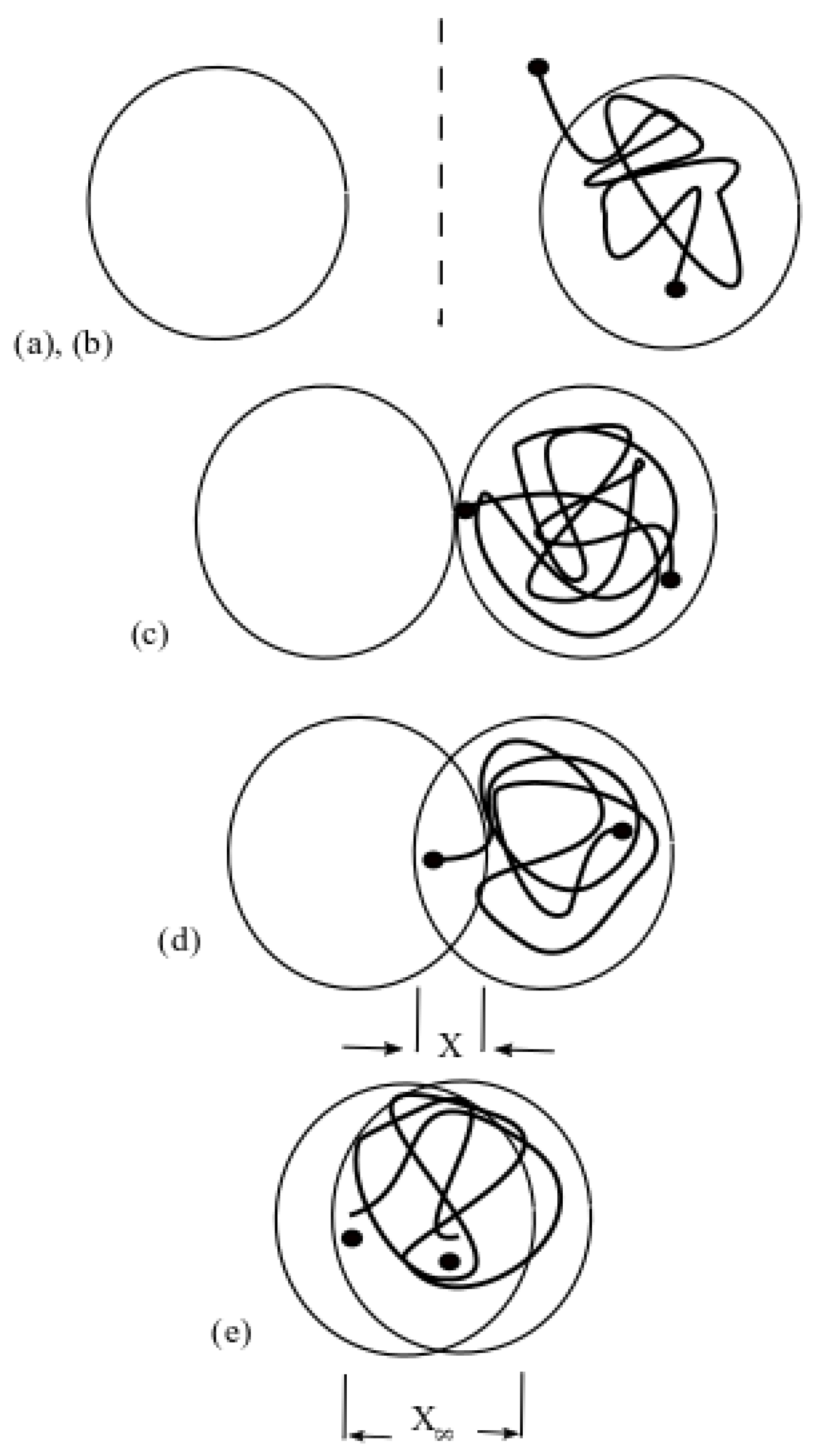
Figure 4.
Log of healing based on fracture load recovery [92]. (Copyright, 1981, Journal of Applied Physics).
Figure 4.
Log of healing based on fracture load recovery [92]. (Copyright, 1981, Journal of Applied Physics).
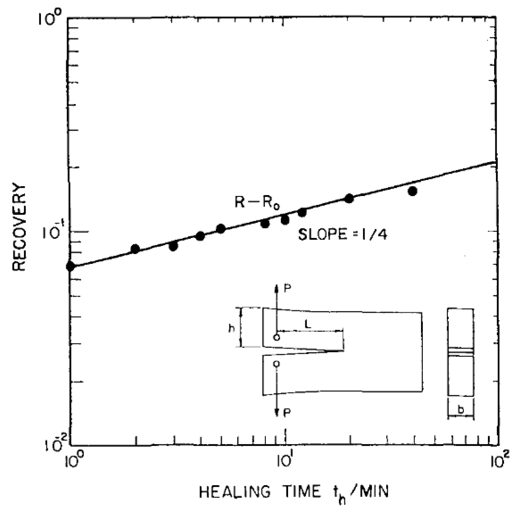
Figure 5.
Variation of the stiffness before and after the rest period [115]. (Copyright, 1998, Journal of engineering mechanics).
Figure 5.
Variation of the stiffness before and after the rest period [115]. (Copyright, 1998, Journal of engineering mechanics).

Figure 6.
Results of repeated recovery test in compression with 120 s loading time and 100 s of rest period. (a) compared creep strain; (b) evolution of the effective damage density [125]. (Copyright, 2010, International Journal of Engineering Science).
Figure 6.
Results of repeated recovery test in compression with 120 s loading time and 100 s of rest period. (a) compared creep strain; (b) evolution of the effective damage density [125]. (Copyright, 2010, International Journal of Engineering Science).

Figure 7.
Microcapsules-based self-healing mechanism: (i) crack formation; (ii) the crack breaks the microcapsules and the healing agent releases into the crack area; (iii) solidification of healing agent in contact with the catalyst [136]. (Copyright, 2012, Construction and Building Materials).
Figure 7.
Microcapsules-based self-healing mechanism: (i) crack formation; (ii) the crack breaks the microcapsules and the healing agent releases into the crack area; (iii) solidification of healing agent in contact with the catalyst [136]. (Copyright, 2012, Construction and Building Materials).

Figure 8.
Stress–strain response of the healed material with different rest periods [134]. (Copyright, 2013, Computational Mechanics).
Figure 8.
Stress–strain response of the healed material with different rest periods [134]. (Copyright, 2013, Computational Mechanics).

Figure 9.
Configuration of the nonlinear self-healing theory [89].
Figure 9.
Configuration of the nonlinear self-healing theory [89].
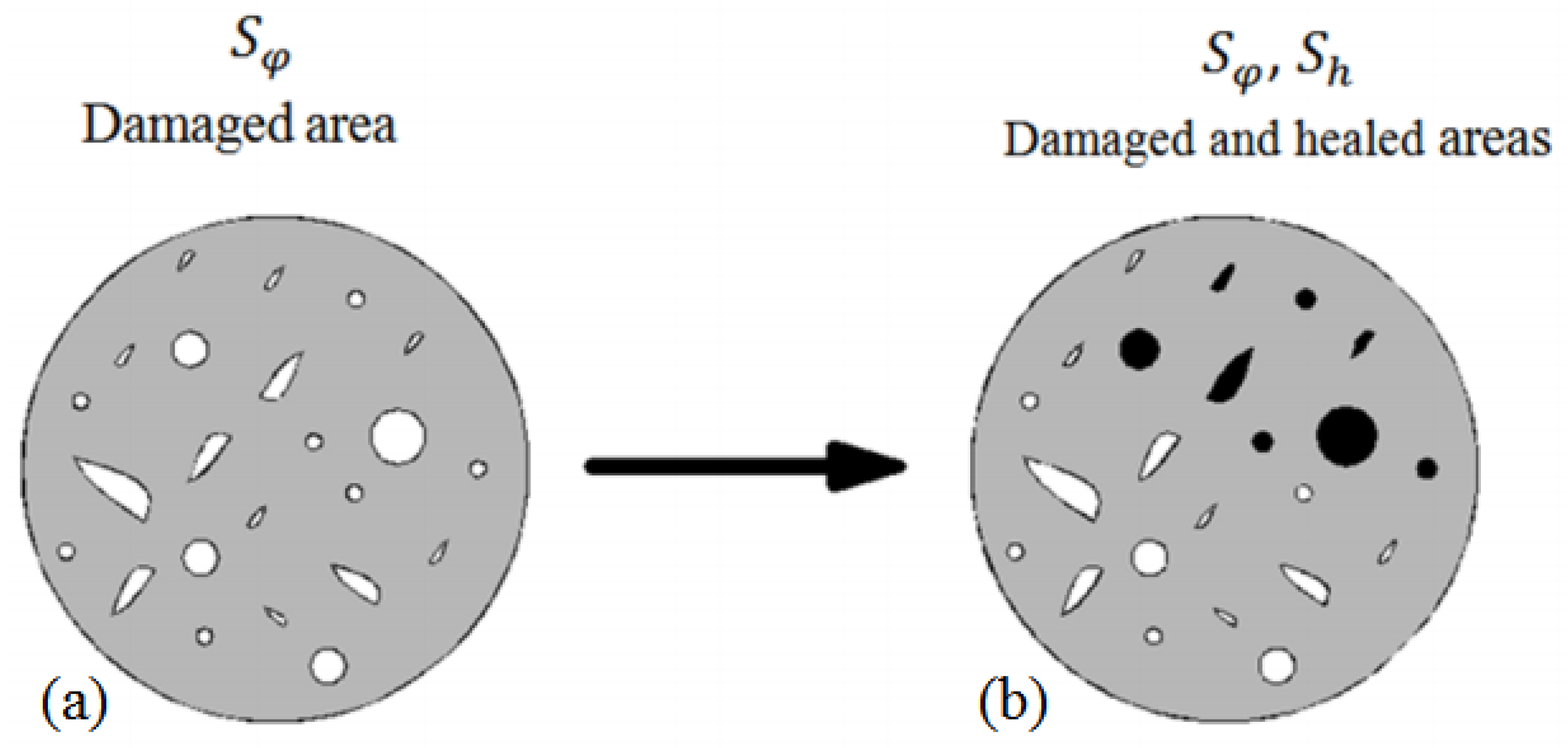
Figure 10.
Stress–time response of the uncoupled damage healing model with various rest periods [88]. (Copyright, 2018, Theoretical and Applied Fracture Mechanics).
Figure 10.
Stress–time response of the uncoupled damage healing model with various rest periods [88]. (Copyright, 2018, Theoretical and Applied Fracture Mechanics).

Figure 11.
Stress–time response of the coupled damage healing model with different values of the material parameter [88]. (Copyright, 2018, Theoretical and Applied Fracture Mechanics).
Figure 11.
Stress–time response of the coupled damage healing model with different values of the material parameter [88]. (Copyright, 2018, Theoretical and Applied Fracture Mechanics).
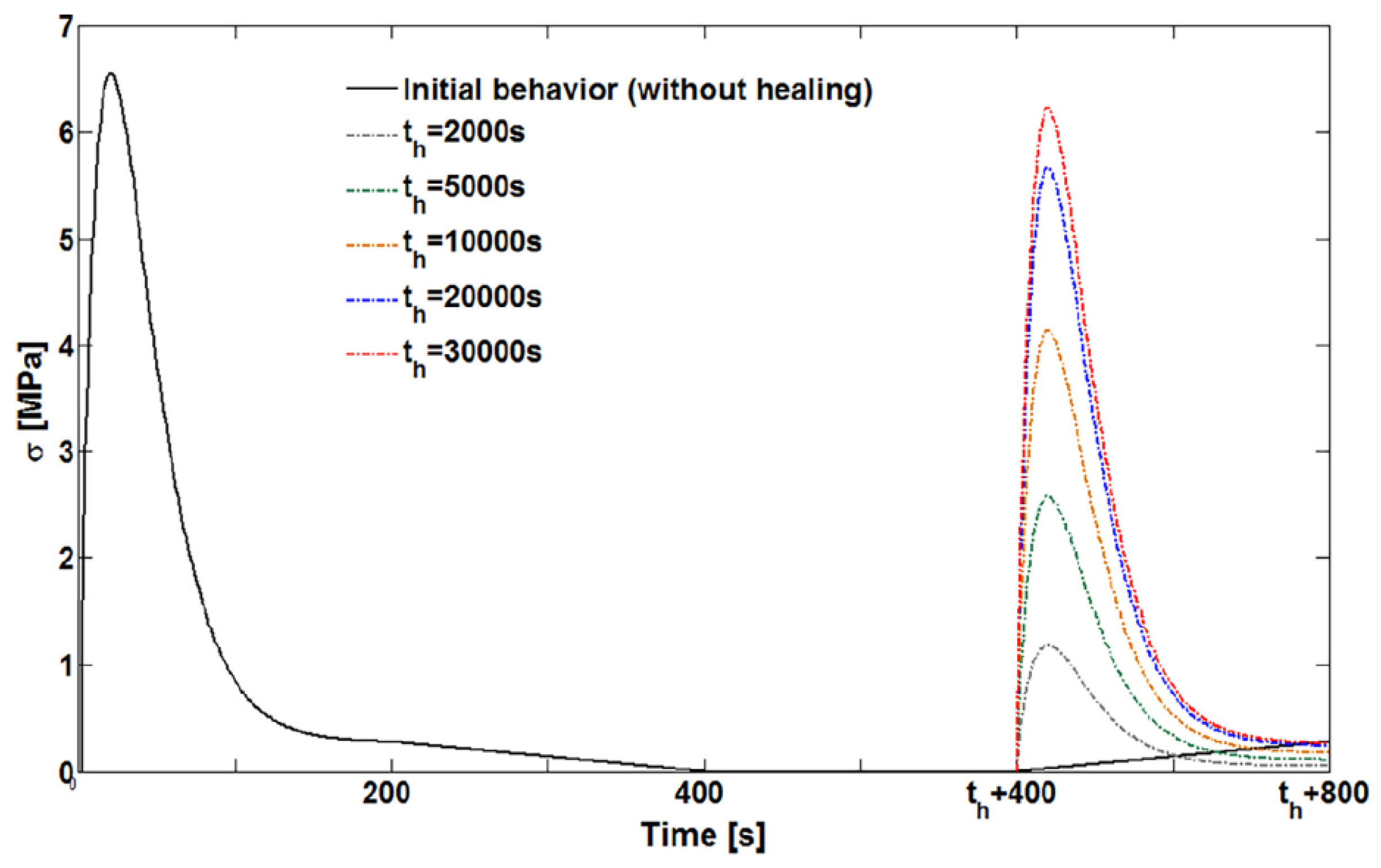
Figure 12.
(a) fictitious damaged state; (b) fictitious healed state; (c) fictitious effective healed material state; and (d) fictitious damaged state [161]. (Copyright, 2012, The Royal Society).
Figure 12.
(a) fictitious damaged state; (b) fictitious healed state; (c) fictitious effective healed material state; and (d) fictitious damaged state [161]. (Copyright, 2012, The Royal Society).

Figure 13.
Effect of creep recovery load on evolution of degradation (left); evolution of axial strain due to healing parameter effect resulting from the creep-recovery test (right) [165]. (Copyright, 2016, Springer Nature).
Figure 13.
Effect of creep recovery load on evolution of degradation (left); evolution of axial strain due to healing parameter effect resulting from the creep-recovery test (right) [165]. (Copyright, 2016, Springer Nature).
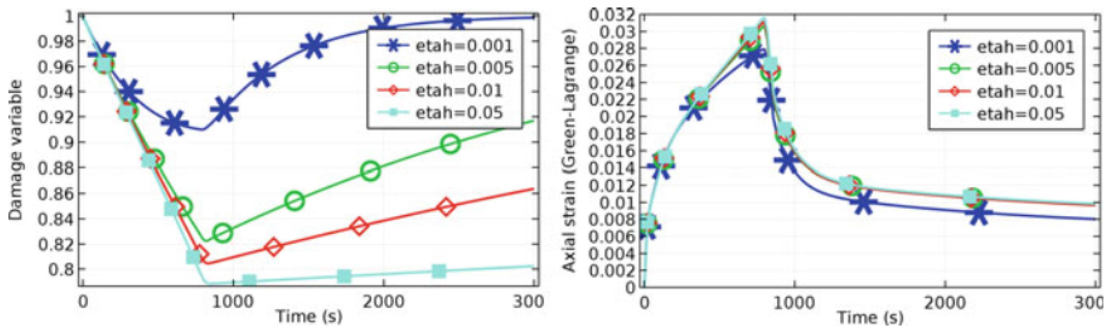
Figure 14.
Damaged, healed, and super healed material states [89]. (Copyright, 2018, Journal of engineering mechanics).
Figure 14.
Damaged, healed, and super healed material states [89]. (Copyright, 2018, Journal of engineering mechanics).

Figure 15.
Variation of material stiffness from initial to super healed state [89]. (Copyright, 2018, Journal of engineering mechanics).
Figure 15.
Variation of material stiffness from initial to super healed state [89]. (Copyright, 2018, Journal of engineering mechanics).
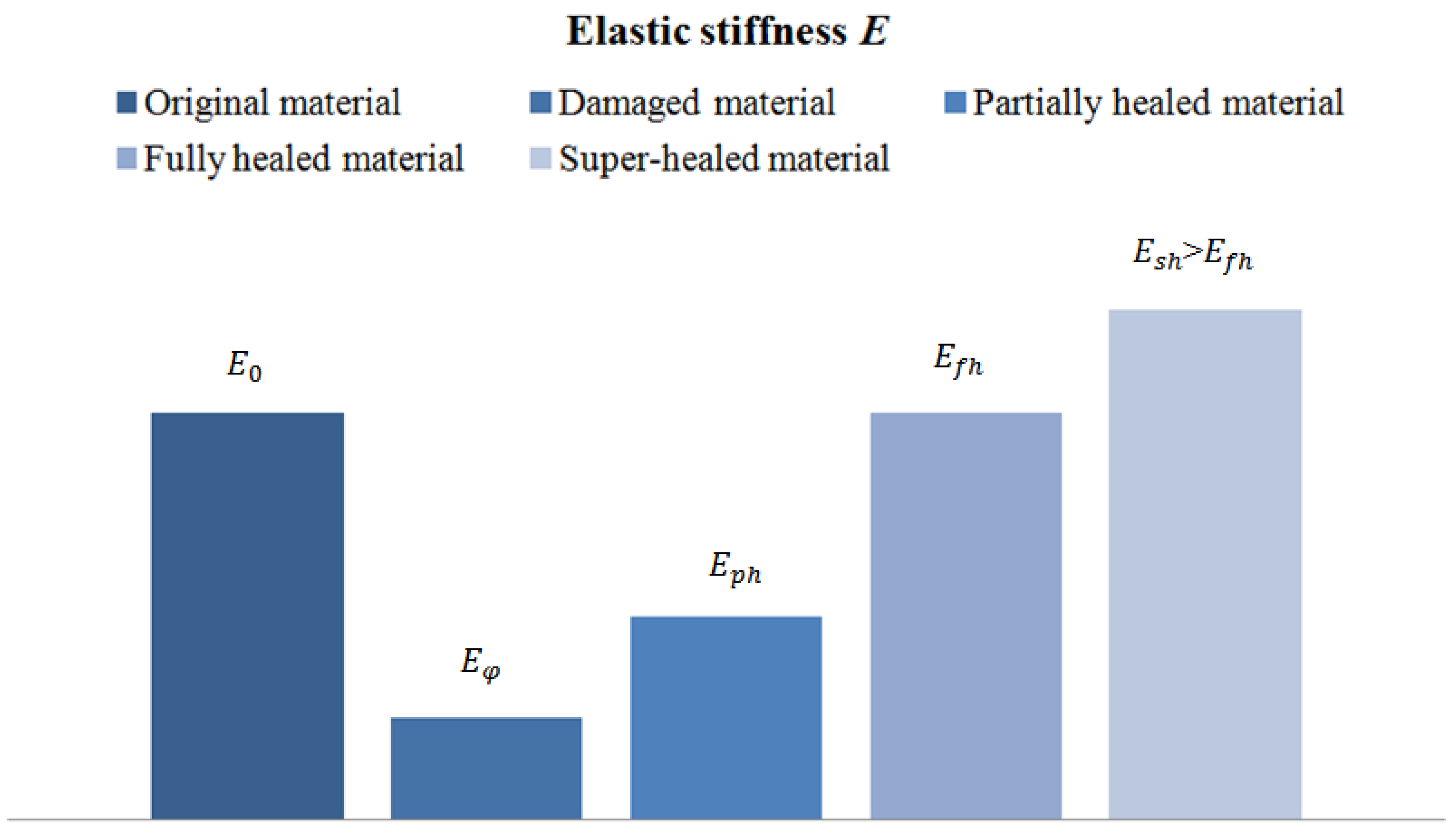
Figure 16.
Effects of (a) healing and (b) super healing mechanisms [89]. (Copyright, 2018, Journal of engineering mechanics).
Figure 16.
Effects of (a) healing and (b) super healing mechanisms [89]. (Copyright, 2018, Journal of engineering mechanics).

Figure 17.
Comparison between linear, generalized nonlinear and quadratic models: (a) self-healing models; (b) super healing models [89]. (Copyright, 2018, Journal of engineering mechanics).
Figure 17.
Comparison between linear, generalized nonlinear and quadratic models: (a) self-healing models; (b) super healing models [89]. (Copyright, 2018, Journal of engineering mechanics).

Figure 18.
Schematic of liquid state healing mechanism [173]. (Copyright, 2009, John Wiley & Sons).
Figure 18.
Schematic of liquid state healing mechanism [173]. (Copyright, 2009, John Wiley & Sons).

Figure 19.
(a) solute diffusion along grain boundary and (b) mobile dislocation moving solutes to a pore [173]. (Copyright, 2009, John Wiley & Sons).
Figure 19.
(a) solute diffusion along grain boundary and (b) mobile dislocation moving solutes to a pore [173]. (Copyright, 2009, John Wiley & Sons).
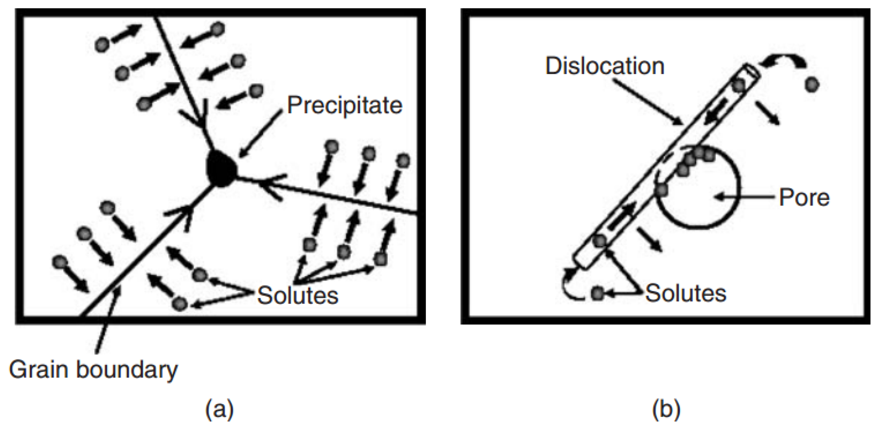

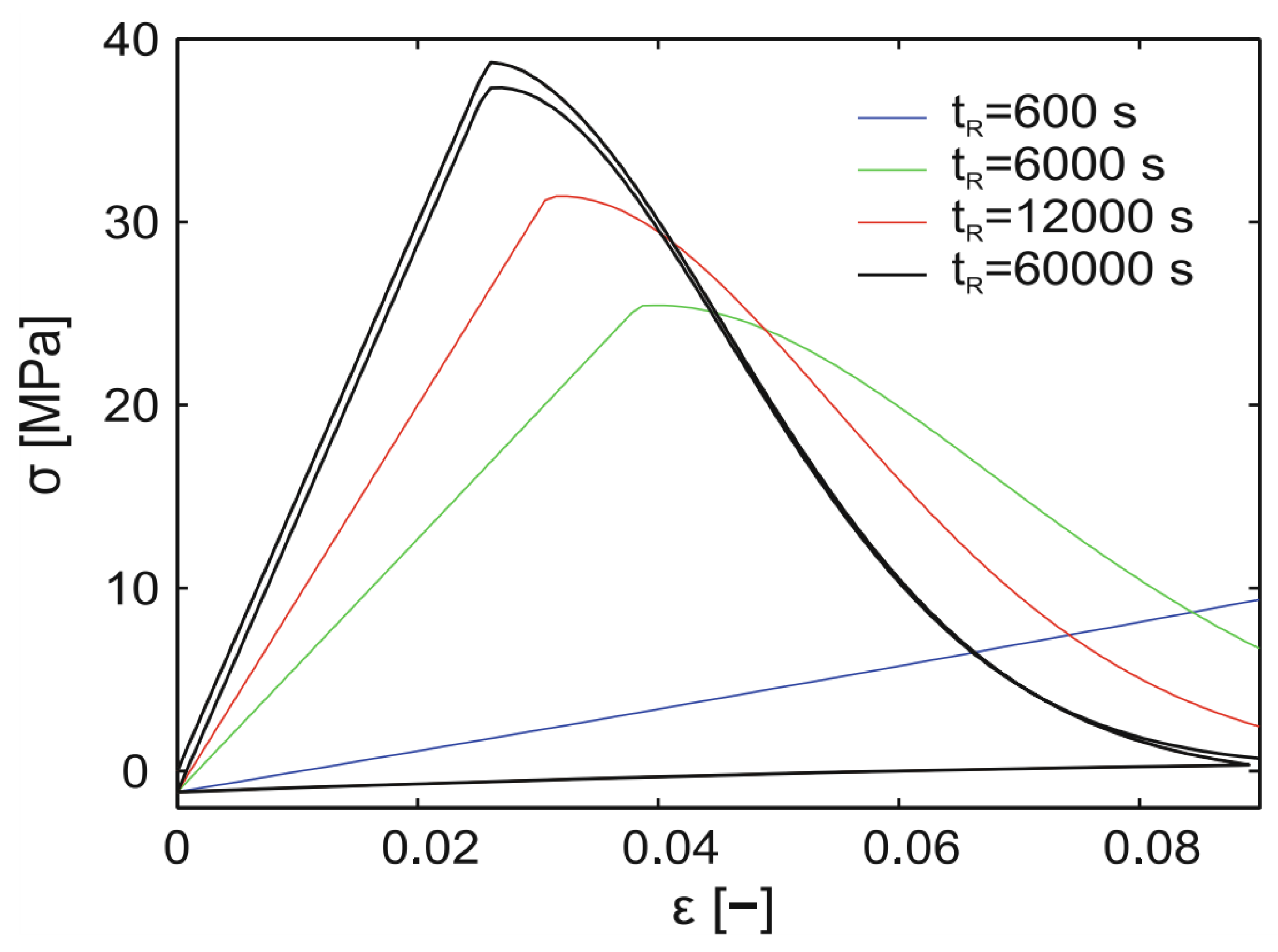
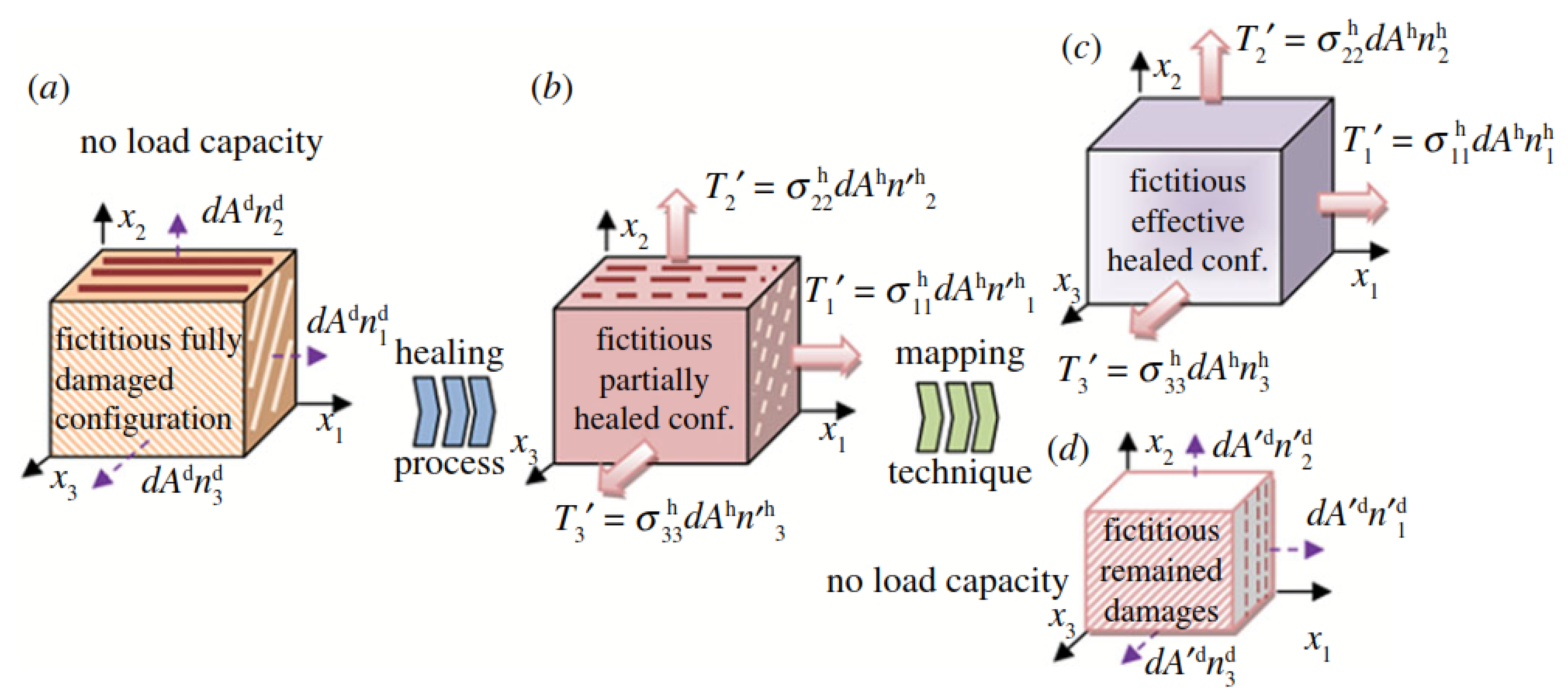
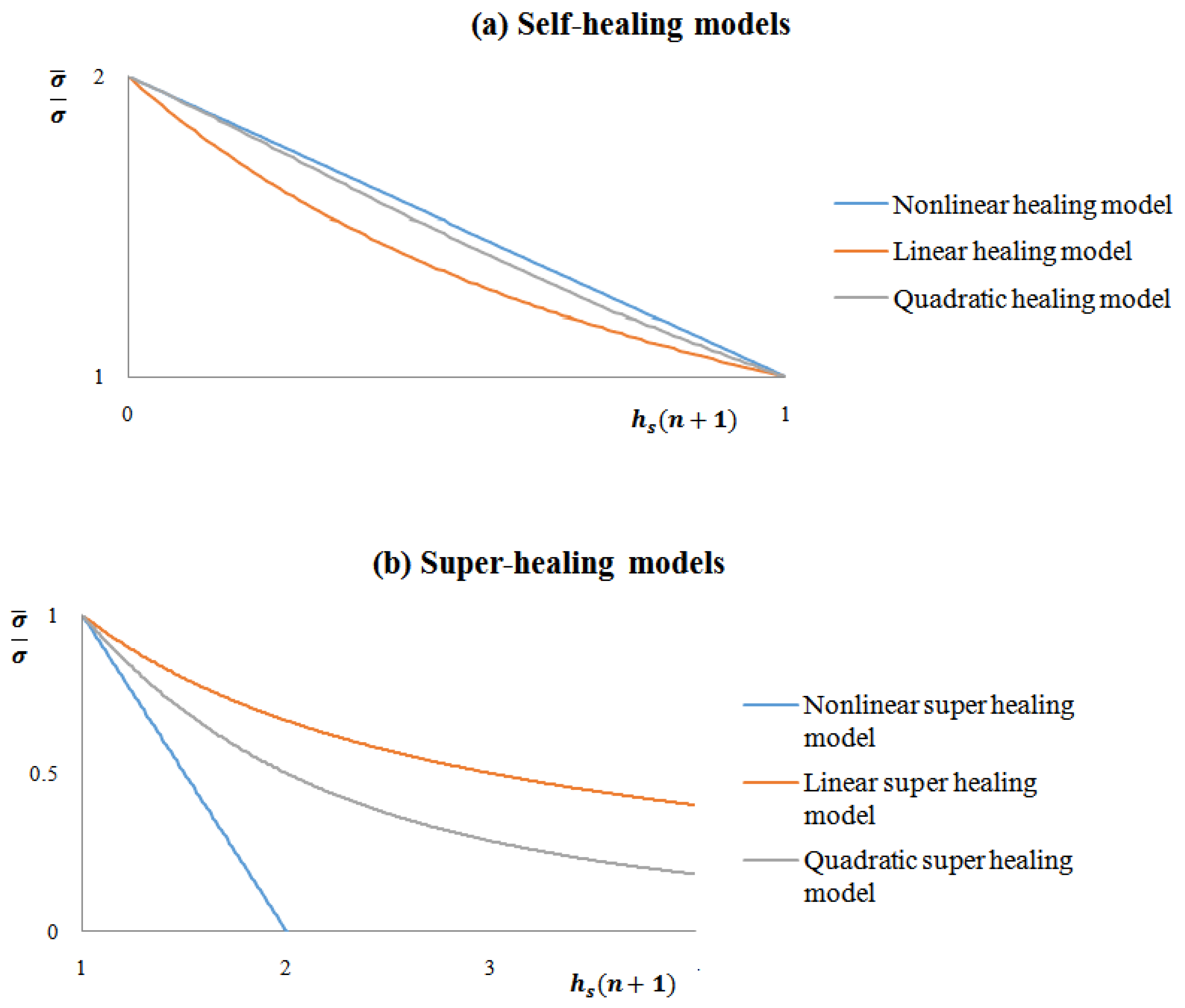
Table 1.
Comparison between super healing models.
| Super Healing Model | Equation of the Ratio | Equation of the Ratio |
|---|---|---|
| Linear super healing (LSH) | ||
| Generalized nonlinear super healing (NSH) | ||
| Quadratic super healing (QSH) |
Table 2.
Elastic modulus in the damaged, healed, and super healed material states using the hypotheses of elastic strain equivalence and elastic energy equivalence.
Table 2.
Elastic modulus in the damaged, healed, and super healed material states using the hypotheses of elastic strain equivalence and elastic energy equivalence.
| Elastic Strain Equivalence | Elastic Energy Equivalence | |||
|---|---|---|---|---|
| Phase | Elastic Modulus | Variable | Elastic Modulus | Variable |
| Damage | ||||
| Healing | ||||
| Super healing | ||||
© 2018 by the authors. Licensee MDPI, Basel, Switzerland. This article is an open access article distributed under the terms and conditions of the Creative Commons Attribution (CC BY) license (http://creativecommons.org/licenses/by/4.0/).
Share and Cite
MDPI and ACS Style
Oucif, C.; Mauludin, L.M. Continuum Damage-Healing and Super Healing Mechanics in Brittle Materials: A State-of-the-Art Review. Appl. Sci. 2018, 8, 2350. https://doi.org/10.3390/app8122350
AMA Style
Oucif C, Mauludin LM. Continuum Damage-Healing and Super Healing Mechanics in Brittle Materials: A State-of-the-Art Review. Applied Sciences. 2018; 8(12):2350. https://doi.org/10.3390/app8122350
Chicago/Turabian StyleOucif, Chahmi, and Luthfi Muhammad Mauludin. 2018. "Continuum Damage-Healing and Super Healing Mechanics in Brittle Materials: A State-of-the-Art Review" Applied Sciences 8, no. 12: 2350. https://doi.org/10.3390/app8122350
Note that from the first issue of 2016, this journal uses article numbers instead of page numbers. See further details here.