Article

Obtaining Vital Distances Using Wearable Inertial Measurement Unit for Real-Time, Biomechanical Feedback Training in Hammer-Throw

1
Department of Mathematics & Computer Science, University of Lethbridge, Lethbridge, AB T1K 3M4, Canada
2
School of Physical Education, Shaanxi Normal University, Xian 710119, China
3
Department of Physical Education, Xinzhou Teachers’ University, Shanxi 034000, China
4
Biomechanics Lab, Faculty of Arts & Science, University of Lethbridge, Lethbridge, AB T1K 3M4, Canada
*
Author to whom correspondence should be addressed.
Appl. Sci. 2018, 8(12), 2470; https://doi.org/10.3390/app8122470
Submission received: 29 October 2018 / Revised: 26 November 2018 / Accepted: 30 November 2018 / Published: 3 December 2018
(This article belongs to the Special Issue Precision Dimensional Measurements)

Abstract

:
The hammer throw is one of the regular track and field competitions, but unlike other events, it has not seen a new world record for over three decades. The standstill may be caused by the lack of scientifically based training. In our previous work, we have developed a wireless/wearable device for the wire tension measurement in order to develop real-time biomechanical feedback training. In this paper, we show the improvement of our wearable system by adding two sensors for tracking of two vital vertical distances. The paper describes the details related to the development of turning an inertial measurement unit into a tracking device for the dynamic distances. Our preliminary data has shown that the dynamic data of the hip and wrist could be used for revealing the coordination between the upper and the lower limbs during a throw. In conjunction with wearable wire-tension measurement, various motor control patterns employed for hammer throwing could be demystified. Such real-time information could be valuable for hammer-throw learning and optimization. Further studies are required to verify the potentials of the wearable system for its efficiency and effectiveness in coaching practice.

1. Introduction

Optimization of any sport skill requires re-organization of limbs coordination responsible for governing the movement performance [1]. This type of motor learning can be enhanced through a number of methods that are utilized in research and application settings alike. In general, verbal feedback of coaches in real-time is commonly used as a preliminary means of instilling motor learning [1,2]. Due to the rapidity and complexity of some sport skills as well as invisibility of some parameters (e.g., force), the real-time feedback of coaches is often a subjective guess based on experience. For increasing the reliability of feedback in training, biomechanical means are used to supplement the verbal instructions [3,4,5,6]. The hammer throw is such a sport skill that needs a combination of a coach’s experience and biomechanical feedback in elite sport training to facilitate motor learning and optimize outcomes.
Men’s hammer throw has been part of Olympics track and field competitions since 1900, but unlike other events, the hammer throw has not seen a new world record since 1986 [7]. This standstill may be caused by the lack of scientifically based training. While extensive 3D motion analysis technologies do supply highly trustworthy information for human motor skill quantification [8,9,10,11], due to their drawbacks, the analysis and feedback has traditionally occurred offline after completion of a given testing session, i.e., it is post-measurement feedback, rather than real-time [11,12,13,14]. The drawbacks of a 3D motion capture system include complicated operation, high cost, long calibration and setup procedures, time-consuming course on data collection, processing, analysis as well as the movement constrains induced by dozens of capture markers attached on a subject’s body [15]. These drawbacks have hindered the use of 3D motion capture systems in sport training practice. As a consequence, research has been initiated to develop real-time biomechanical feedback devices for hammer throw training, beginning with wire-tension measurement [12].
Most recently, a pilot study [16] using 3D motion capture technology (Figure 1) found that the timely displacements of hip and wrist may be used to reveal the upper and lower limbs’ coordination when analyzing hammer throw. The pilot study has shown that the timely change of vertical displacements of hip and wrist are closely related to the turning speed, the ratio of one-leg/two-leg support (power generation), and hammer velocity change during the skill performance. Therefore, obtaining the dynamic distance data of these two anatomical landmarks would be vital for real-time feedback training.
The results of the two studies would suggest that a combination of the wire-tension measurement and the dynamic vertical-displacements of hip and wrist could have great potential for substituting 3D motion capture technology in the skill analysis of the hammer throw. Since real-time wire-tension is developed (i.e., already wearable) [12], developing wearables for tracking hip and wrist movements would realize the real-time biomechanical feedback learning/training in the hammer throw. Encouraged by the results of the studies, we are aiming at developing a practical wearable device for pursuing real-time training. This paper will highlight our approach of using the inertial measurement unit (IMUs) as a practical approach for the development of a wearable system for biomechanical feedback training in the hammer throw.

2. Materials and Methods

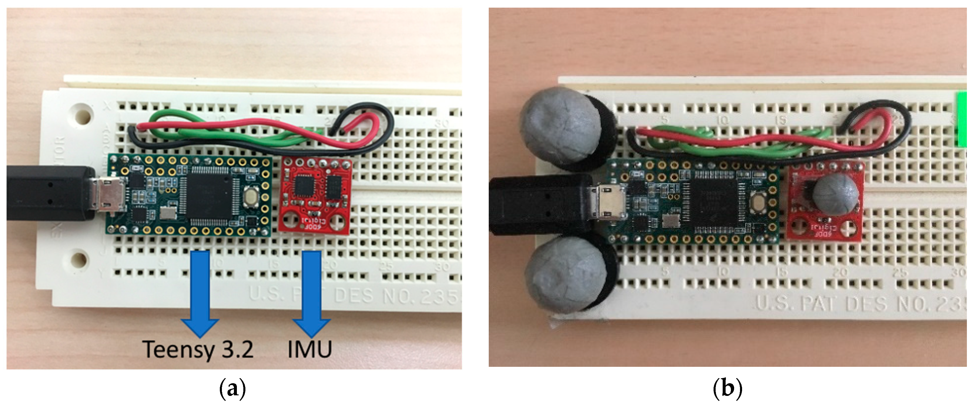
2.1. Hardware Configuration

The constitution of the hardware in our system is straightforward. Intuitively shown in Figure 2a, a six degree of freedom (6DoF) IMU [17] and a Teensy 3.2 board [18] were connected with each other. We built these on a breadboard as a testing device with an Arduino Mega board in our previous work for the wire-tension measurement [12]. The 6DoF means there is a tri-axial accelerometer and a tri-axial gyroscope, which can return the acceleration and the angular speed, respectively, on the X, Y, and Z axis of a coordinate system. In other words, 6DoF can be described as the freedom of movement of a rigid body in three-dimensional space, which refers to the following: Forward/back (on X axis), left/right (on Y axis), up/down (on Z axis), roll (around X axis), pitch (around Y axis), and yaw (around Z axis). In our particular case, we do not need the magnetometer, which can be potentially combined with the accelerometer and the gyroscope to construct a 9DoF IMU. In our application, the IMU is designed as a combo board, which has the accelerometer, ADXL345, and the gyroscope, TG3200. The Teensy 3.2 board is a breadboard-friendly microcontroller, which can be programmed in Arduino IDE (Integrated Development Environment). Compared to several Arduino boards, the current one is smaller than the Arduino UNO and Mega boards, and it has its own USB (Universal Serial Bus) port while Arduino Mini does not have one, which makes it relatively easier to be programmed.
In addition, as shown in Figure 2b, we attached three motion capture markers (two are 9 mm in diameter and one is 5 mm in diameter) on the sensor device for constructing a capture model for 3D motion capture using a 10-camera VICON MX40 motion capture system (VICON Motion Systems, Oxford Metrics Ltd., Oxford, England). The motion capture rate was set at 200 frames/s. Calibration residuals were determined in accordance with VICON’s guidelines and yielded positional data accurate within 1 mm. The VICON data was used to help us develop a tracking algorithm of the IMUs in the vertical direction.

2.2. Methodology

First, we needed to configure the IMU in an Arduino sketch program by applying the Wire library [19], which allowed communication with I2C (Inter-Integrated circuit) devices. This configuration program was uploaded to the Teensy 3.2 microcontroller. It was used to set up the accelerometer and the gyroscope. We set the data format register of the accelerometer to 0 × 09, which could set the acceleration range from −4 g (1 g = 9.8 m/s2) to +4 g. According to the datasheet of ADXL345 [20], it sets the device to a full resolution mode, where the output resolution increases with the g range set by the range bits to maintain a 3.9 mg/LSB scale factor. This setting information is useful for converting the unit of the raw output data to g. We set the power control register to 0 × 08 to make the accelerometer in a measurement mode. Should we want to have the minimum power consumption, we could set this register to 0 × 00 to make it in a standby mode. Similarly, we configured the ITG3200 gyroscope’s settings in this program according to its datasheet [21]. The range of rotation speed was set from -2000 degree/second (dps) to +2000 degree/second, which was a full-scale range. The sensitivity was 14.375 LSB, which was also useful for converting the unit of the raw output data to dps. The low pass filter bandwidth was set to 98 Hz, and its sampling rate was set to 100 Hz. In addition, we implemented the functions for reading and outputting the acceleration values relative to the earth and the angular speed values in the Arduino sketch program.
The next step was to do some calibration work. We applied the sensitivity values, 256 LSB and 14.375 LSB, to convert the units of the raw output of accelerometer and the raw output of gyroscope to g and dps, respectively. These values can be found in the datasheets of the sensors. We implemented a function of calculating the offsets (chip specific) of the first 200 samples in the Arduino sketch program.
Finally, we needed to apply an algorithm to predict the orientation. Kalman-based filters have been widely used in orientation estimation [22]. In the beginning, we tried to implement a complementary Kalman-based algorithm. However, the result of the orientation estimation was bad due to a drifting error that kept occurring in calculating the velocities. Figure 3 displays the acceleration data obtained from the IMU sensor and the corresponding velocity data, which was calculated by the complementary Kalman-based filter. Obviously, the velocity data cannot come back to zero at the end of the test, which is known as a drifting error. Then, we started looking for some other ways to get the accurate orientation. Madgwick’s algorithm [23] is also known as Madgwick’s MARG (magnetic, angular rate, and gravity) filter or AHRS (attitude and heading reference systems) algorithm. As Madgwick mentions in his work, Kalman-based filters are difficult to implement because they may require sampling rates far exceeding the subject bandwidth. Our sensor device has a fairly low sampling rate, which is only 50 Hz. This is probably one of the reasons that we experienced the velocity drifting error. As Madgwick claims in his study, his algorithm can be effective even at lower sampling rates, like 10 Hz. In addition, Madgwick compares the performance of his algorithm with a Kalman-based filter in his study, and the results indicate his algorithm has a slightly better accuracy. Therefore, we decided to apply Madgwick’s algorithm. We tried two versions of his filters to predict the orientation in MATLAB R2017a.

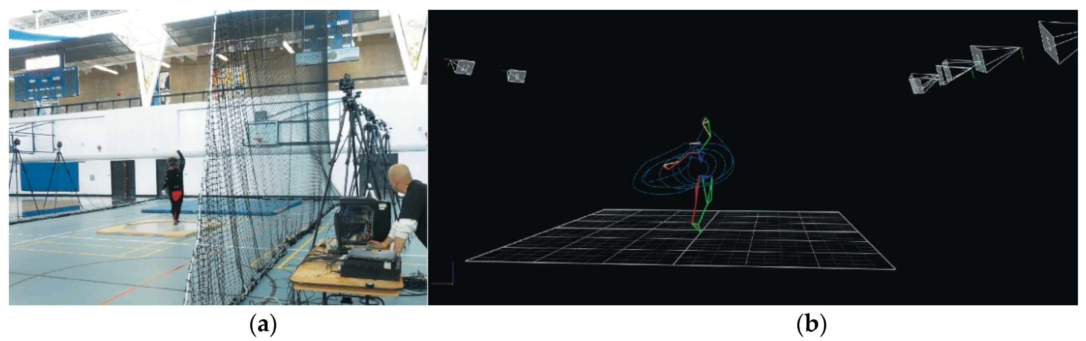
2.3. Our Prototype and In-Field Test

After the development of the wearables for vertical distance monitoring, we built our prototype for the real-time biomechanical feedback training of the hammer throw. The prototype integrated the two newly developed distance sensors into our Arduino Mega board developed in our previous work for wire-tension monitoring during the hammer throw [12], increasing the device capacity to monitor three key variables in real time. The two new distance sensors were buried into a self-made belt and a self-made armband, attached to the waist and right wrist, respectively.
The new device was tested in the field. A varsity-level athlete (male, 25 years, 81 kg, 1.75 m with seven years training experience) tried out the real-time feedback device. Our wearable device permitted considerable freedom of movement for the subject with negligible influence on his performance. Taking advantage of this, we placed no restrictions on the subject’s movements during the in-field test to preserve his normal “control style”. Four trials were done.

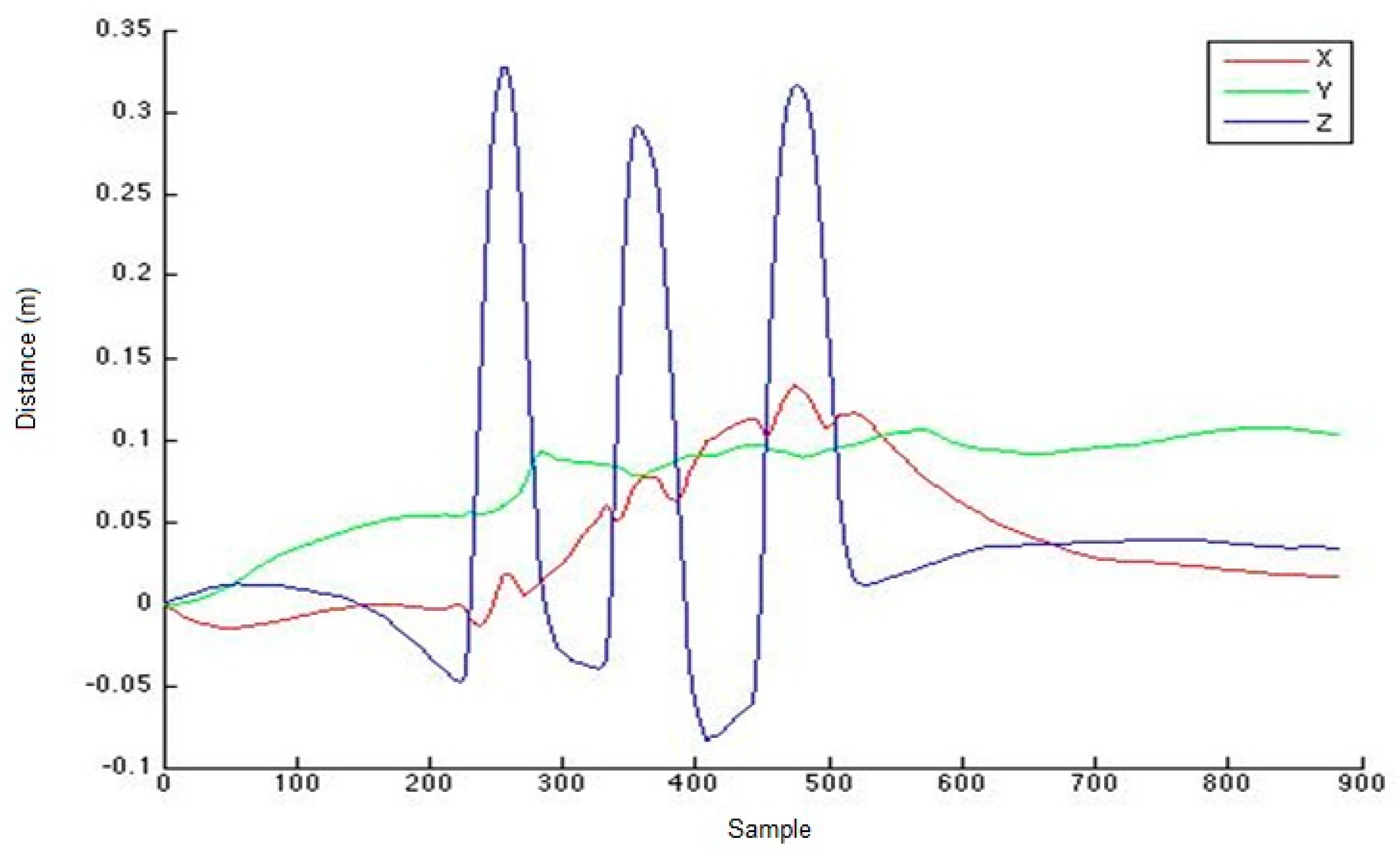
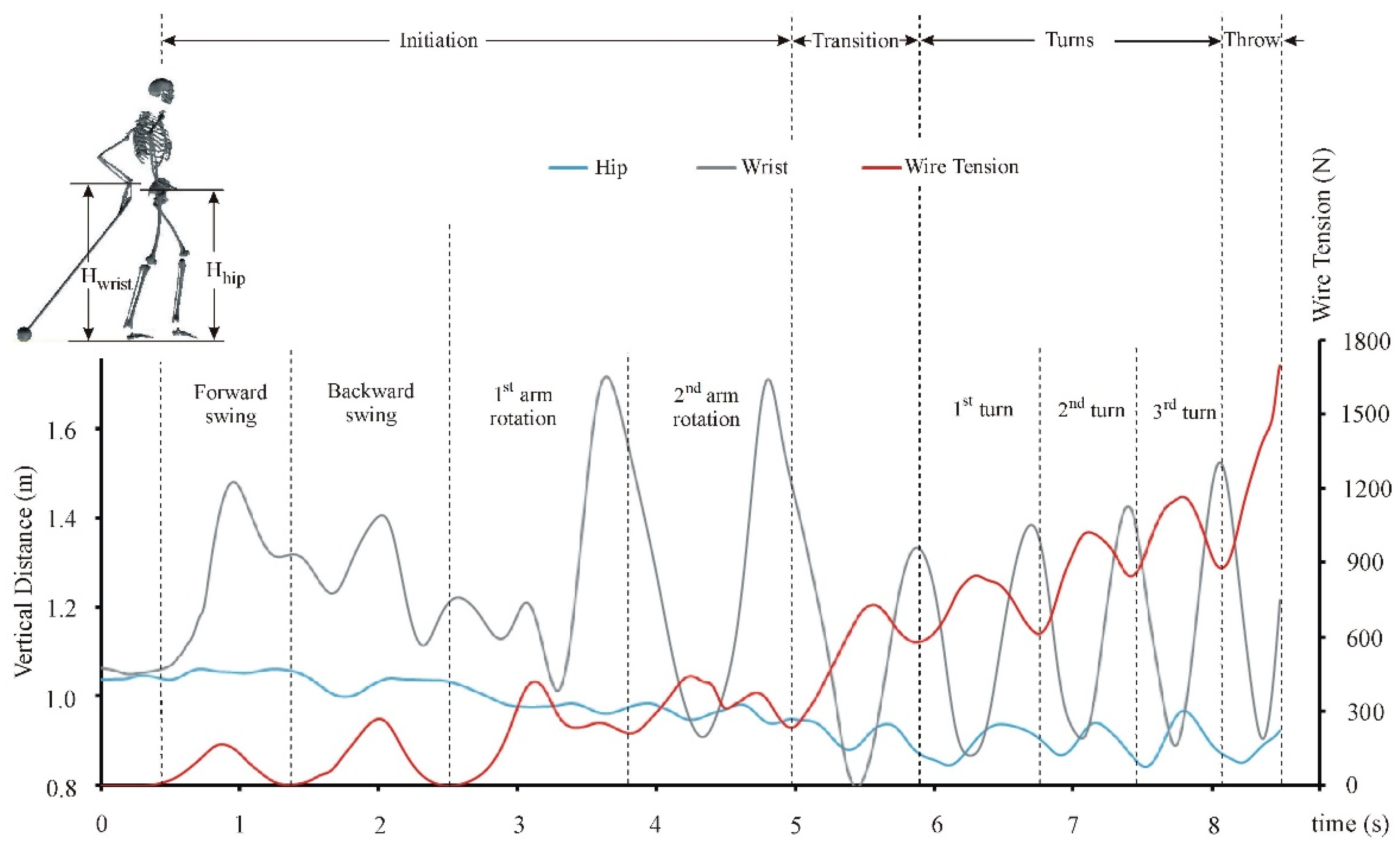
3. Results and Discussion

The result of the test by applying Madgwick’s filter is satisfied. During a test, we moved our system device up and down three times. As shown in Figure 4, we got relatively accurate feedback of the 3D positioning data. Indeed, the Madgwick algorithm eliminates the drifting error from integrating the velocities. The three different curves stand for the changing distances over time on the X axis, Y axis, and Z axis in a 3D space. The dynamic distance on the Z axis (blue lines) shows exactly three times up and down of the device. The range of vertical movements is ~0.33 m for the first moving-up and down, ~29 cm for the second circle, and ~32 cm for the last one, respectively. The next step is to validate the accuracy of the device.
It is well known that 3D motion capture technology provides accurate and objective analysis of a variety of human motor skills [14,24,25,26,27]. Therefore, we employed the synchronized data collection of the IMU and 3D motion capture (Figure 1b) for validating and improving the accuracy of the IMU device. There were eight synchronized tests performed to obtain thousands of data for our validation. Since we aimed to gain the dynamic vertical distance, the validation of the Z axis was selected. Figure 5 shows a typical test data. The synchronized data demonstrate a matching vertical excursion over time between the IMU data and the accurate 3D motion capture data. The results suggest that our device works principally.
A magnitude comparison shows that the excursion of the VICON data was larger than that of the IMU data (Figure 5). A timely comparison between the synchronized data of all trials revealed that the two excursions ran in a quasi-parallel way, which suggested that we could apply a factor for re-calibrating the IMU device to improve the accuracy of the IMU data. After the quantitative comparison between the two excursions of all trials, a re-calibration factor of 1.31 was determined. After the simple re-calibration, a renewed synchronized measurement was done and the result is shown in Figure 6. This time, the average data error of our IMU data decreases to under 6%, which is accurate enough for sport skills analysis using the biomechanical modeling method [28,29,30,31,32].
Finally, it should be noted that our device needs an initial value for its application. As shown in Figure 6, the device will start at zero regardless of its actual vertical position. Therefore, for its application in the hammer throw, an accurate feedback needs the initial heights of the hip and wrist (Hhip and Hwrist) as shown in Figure 7.
The in-field test on the college-level athlete using our prototype device confirms the potential of using wire-tension and IMUs in real-time feedback training (Figure 7). In practice, the motor control of the hammer throw could be divided into four phases: Initiation, transition, turns, and throw. The goal of the initiation phase is to launch the circulation of the hammer around the body. It commonly consists of a forward and backward swing of the hammer (i.e., to set the hammer to motion) and two over-head arm rotations (i.e., to set the hammer into rotation). The transition phase aims to switch the body from standing posture to the first body rotation, building a rotating system of the body and the hammer. The phase of turns accelerates the rotating system of the body and the hammer to their highest circulation. The final phase is the throwing. Our data has revealed the following motor control information: (1) During the transition phase, the upper and lower limbs’ controls are transferring from an unclear coordination pattern to a quasi-out-of-phase coordination in the phase of turns (Figure 7). (2) The transition phase helps the power generation (i.e., wire tension) become in phase (quasi) with the hips’ up-and-down movement, indicating the hammer acceleration depends on the timely flexion/extension of lower limbs. (3) Finally, the characteristic of quasi-out-of-phase between the arm control and wire tension finishes in the transition phase. Would such characteristics appear at different levels of athletes? How can the real-time feedback (i.e., wearable devices) be helpful in optimization of individual hammer-throw skills? Are there additional potentials of wearables in the learning and training of the hammer throw? Future studies are needed to answer the above application questions.

4. Conclusions

In conclusion, we used IMUs to build a wearable sensing system to determine the dynamic vertical distances of the hip and wrist during hammer throws. The dynamic data could play a vital role in skill optimization, as they could be used to reveal the coordination between upper and lower limbs. In conjunction with wearable wire-tension measurement, various motor control patterns during the hammer throw could be demystified. Hence, such a wearable system could realize the real-time biomechanical feedback training for the hammer throw. Such an approach has a great potential to become a coach-friendly tool for effectively learning and/or training in practice. In short, our device could make three potential contributions to hammer throw learning and/or training: (1) Making scientific monitoring from a lab-based environment to in field, (2) simplifying a scientific quantification from using a complicated motion capture system to easily-applied wearables, and (3) transferring the biomechanical feedback training from a post-measurement one to a real-time one. Further studies are required to verify the potentials.

Author Contributions

Y.W. designed, prototyped, programmed the wearable system, and tested its performance; B.W., X.Z. and G.S. analyzed and interpreted the data; G.S. and H.L. proposed the architecture and improved the design; Y.W., H.L. and G.S. prepared the draft; all authors contributed to the revisions and proof reading of the article.

Funding

This research was funded by National Sciences and Engineering Research Council of Canada (NSERC), grant number RGPIN-2014-03648.

Conflicts of Interest

The authors declare no conflict of interest. The founding sponsors had no role in the collection, analyses, or interpretation of data; in the writing of the manuscript, and in the decision to publish the results.

References

  1. Magill, R.A. Motor Learning Concepts and Applications, 6th ed.; McGraw-Hill: Boston, MA, USA, 2001. [Google Scholar]
  2. Schmidt, R.; Lee, T. Motor Learning and Performance: From Principles to Application, 5th ed.; Human Kinetics: Windsor, ON, USA, 2013; p. 336. [Google Scholar]
  3. Shan, G.; Westerhoff, P. Full body kinematic characteristics of the maximal instep Soccer kick by male soccer players and parameters related to kick quality. Sports Biomech. 2005, 4, 59–72. [Google Scholar] [CrossRef] [PubMed]
  4. Zhang, X.; Shan, G. Where do golf driver swings go wrong?—Factors Influencing Driver Swing Consistency. Scand. J. Med. Sci. Sports 2014, 24, 749–757. [Google Scholar] [CrossRef] [PubMed]
  5. Yu, D.; Yu, Y.; Wilde, B.; Shan, G. Biomechanical characteristics of the axe kick in Tae Kwon-Do. Arch. Budo 2012, 8, 213–218. [Google Scholar] [CrossRef]
  6. Shan, G.; Visentin, P.; Zhang, X.; Hao, W.; Yu, D. Bicycle kick in soccer: Is the virtuosity systematically entrainable? Sci. Bull. 2015, 60, 819–821. [Google Scholar] [CrossRef]
  7. IAAF. Hammer Throw. Available online: https://www.iaaf.org/disciplines/throws/hammer-throw (accessed on 11 May 2018).
  8. Shan, G.; Zhang, X. From 2D leg kinematics to 3D full-body biomechanics-the past, present and future of scientific analysis of maximal instep kick in soccer. Sports Med. Arthrosc. Rehabil. Ther. Technol. 2011, 3, 23. [Google Scholar] [CrossRef] [PubMed] [Green Version]
  9. Wan, B.; Shan, G. Biomechanical modeling as a practical tool for predicting injury risk related to repetitive muscle lengthening during learning and training of human complex motor skills. SpringerPlus 2016, 5, 441. [Google Scholar] [CrossRef] [PubMed]
  10. Shan, G.; Daniels, D.; Wang, C.; Wutzke, C.; Lemire, G. Biomechanical analysis of maximal instep kick by female soccer players. J. Hum. Mov. Stud. 2005, 49, 149–168. [Google Scholar]
  11. Shan, G. Influences of Gender and Experience on the Maximal Instep Soccer Kick. Eur. J. Sport Sci. 2009, 9, 107–114. [Google Scholar] [CrossRef]
  12. Wang, Y.; Wan, B.; Li, H.; Shan, G. A wireless sensor system for a biofeedback training of hammer throwers. SpringerPlus 2016, 5, 1395. [Google Scholar] [CrossRef] [Green Version]
  13. Aminian, K.; Najafi, B. Capturing human motion using body-fixed sensors: Outdoor measurement and clinical applications. Comput. Animat. Virtual Worlds 2004, 15, 79–94. [Google Scholar] [CrossRef]
  14. Shan, G.; Zhang, X.; Li, X.; Hao, W.; Witte, K. Quantification of Golfer-club Interaction and Club-type’s Affect on Dynamic Balance during a Golf Swing. Int. J. Perform. Anal. Sport 2011, 11, 417–426. [Google Scholar] [CrossRef]
  15. Shan, G.; Yuan, J.; Hao, W.; Gu, M.; Zhang, X. Regression Equations related to the Quality Evaluation of Soccer Maximal Instep Kick for Males and Females. Kinesiology 2012, 44, 139–147. [Google Scholar]
  16. Wan, B.; Shan, G.; Wang, Y.; Zhang, X.; Li, H. 3D Quantification of Key Parameters for Developing Wearables of Biomechanical Feedback Training in Hammer Throw. Unpubl. Artic. 2018. [Google Scholar]
  17. Sparkfun. SparkFun 6 Degrees of Freedom IMU Digital Combo Board—ITG3200/ADXL345. Available online: https://www.sparkfun.com/products/retired/10121 (accessed on 16 August 2017).
  18. Sparkfun. Teensy 3.2. Available online: https://www.sparkfun.com/products/13736 (accessed on 16 August 2017).
  19. Arduino. Wire Library. Available online: https://www.arduino.cc/en/Reference/Wire (accessed on 11 July 2015).
  20. AnalogDevices. Digital Accelerometer. Available online: https://www.sparkfun.com/datasheets/Sensors/Accelerometer/ADXL345.pdf (accessed on 11 August 2017).
  21. InvenSense. ITG-3200 Product Specification Revision 1.4. Available online: https://www.sparkfun.com/datasheets/Sensors/Gyro/PS-ITG-3200-00-01.4.pdf (accessed on 11 August 2017).
  22. Won, S.-H.; Melek, W.; Golnaraghi, F. Position and orientation estimation using Kalman filtering and particle diltering with one IMU and one position sensor. In Proceedings of the 34th Annual Conference of IEEE Industrial Electronics, Orlando, FL, USA, 10–13 November 2008; pp. 3006–3010. [Google Scholar]
  23. Madgwick, S. An efficient orientation filter for inertial and inertial/magnetic sensor arrays. Rep. x-io Univ. Bristol (UK) 2010, 25, 113–118. [Google Scholar]
  24. Shan, G.B.; Visentin, P. A quantitative three-dimensional analysis of arm kinematics in violin performance. Med. Probl. Perform. Artist. 2003, 18, 3–10. [Google Scholar]
  25. Shan, G. Biomechanical Know-how of Fascinating Soccer-kicking Skills—3D, Full-body Demystification of Maximal Instep Kick, Bicycle kick & Side Volley. In Proceedings of the 8th International Scientific Conference on Kinesiology, Zagreb, Opatija, Croatia, 10–14 May 2017; pp. 133–135. [Google Scholar]
  26. Visentin, P.; Li, S.; Tardif, G.; Shan, G. Unraveling mysteries of personal performance style; biomechanics of left-hand position changes (shifting) in violin performance. PeerJ 2015, 3, e1299. [Google Scholar] [CrossRef] [PubMed]
  27. Shan, G.; Zhang, X.; Meng, M.; Wilde, B. A Biomechanical Study for Developing Wearable-Sensor System to Prevent Hip Fractures among Seniors. Appl. Sci. 2017, 7, 771. [Google Scholar] [CrossRef]
  28. Shan, G.; Bohn, C. Anthropometrical data and coefficients of regression related to gender and race. Appl. Ergon. 2003, 34, 327–337. [Google Scholar] [CrossRef]
  29. Shan, G.; Bohn, C.; Sust, M.; Nicol, K. How can dynamic rigid-body modeling be helpful in motor learning?—Learning performance using dynamic modeling. Kinesiology 2004, 36, 182–191. [Google Scholar]
  30. Shan, G.; Sust, M.; Simard, S.; Bohn, C.; Nicol, K. How can dynamic rigid-body modeling be helpful in motor learning?—Diagnosing performance using dynamic modeling. Kinesiology 2004, 36, 5–14. [Google Scholar]
  31. Ballreich, R.; Baumann, W. Grundlagen der Biomechanik des Sports (The Basics of Biomechanics in Sports); Enke Verlag: Stuttgart, Germany, 1996. [Google Scholar]
  32. Shan, G.; Zhang, X.; Wan, B.; Yu, D.; Wilde, B.; Visentin, P. Biomechanics of Coaching Maximal Instep Soccer Kick for Practitioners. Interdiscip. Sci. Rev. 2018. [Google Scholar] [CrossRef]
Figure 1. The 3D motion capture of hammer throw. (a) The set-up of the data collection; (b) a sample of the 3D data.
Applsci 08 02470 g001
Figure 2. (a) Teensy 3.2 and Inertial Measurement Unit (IMU) connected on a breadboard; (b) Teensy 3.2 and IMU connected on a breadboard with motion capture markers.
Applsci 08 02470 g002
Figure 3. (a) The acceleration data obtained from the IMU sensor; (b) the corresponding velocity data, which was calculated by the complementary Kalman-based filter.
Applsci 08 02470 g003
Figure 4. The 3D positioning data obtained by the IMU with the Madgwick filter.
Applsci 08 02470 g004
Figure 5. A synchronized test data obtained from 3D motion capture (VICON data, top, sampling rate 200 Hz) and our IMU device without calibration (IMU data, bottom, sampling rate 50 Hz).
Applsci 08 02470 g005
Figure 6. A renewed synchronized test data obtained from 3D motion capture (VICON data, top, sampling rate 200 Hz) and our IMU device after calibration (IMU data, bottom, sampling rate 50 Hz).
Applsci 08 02470 g006
Figure 7. The upper and lower limb coordination (i.e., motor control pattern) revealed by the vertical distances of hip and wrist as well as the wire tension during a hammer throw by a college-level athlete.
Applsci 08 02470 g007

