Cracking Risk and Overall Stability Analysis of Xulong High Arch Dam: A Case Study

1
Department of Hydraulic Engineering, Tsinghua University, Beijing 100084, China
2
Changjiang Institute of Survey, Planning, Design and Research, Wuhan 430010, China
*
Author to whom correspondence should be addressed.
Appl. Sci. 2018, 8(12), 2555; https://doi.org/10.3390/app8122555
Submission received: 31 October 2018
/
Revised: 28 November 2018
/
Accepted: 3 December 2018
/
Published: 10 December 2018
(This article belongs to the Special Issue Computational Methods for Fracture)
Abstract
:Featured Application
The cracking risk, the overall stability, and the reinforcement measures are directly related to the long-term stability of arch dams. The three safety factors and five stress zones have a great significance for arch dam-foundation design of cracking control and overall stability evaluation.
Abstract
It is of great significance to study the cracking risk, the overall stability, and the reinforcement measures of arch dams for ensuring long-term safety. In this study, the cracking types and factors of arch dams are summarized. By employing a nonlinear constitutive model relating to the yielding region, a fine three-dimensional finite element simulation of the Xulong arch dam is conducted. The results show that the dam cracking risk is localized around the outlets, the dam heel, and the left abutment. Five dam stress zones are proposed to analysis dam cracking state base of numerical results. It is recommended to use a shearing-resistance wall in the fault f57, replace the biotite enrichment zone with concrete and perform consolidation grouting or anchoring on the excavated exposed weak structural zone. Three safety factors of the Xulong arch dam are obtained, K_1 = 2~2.5; K_2 = 5; K_3 = 8.5, and the overall stability of the Xulong arch dam is guaranteed. This study demonstrates the significance of the cracking control of similar high arch dams.
1. Introduction
A series of super-high arch dams (height over 200 m) have been constructed or are being planned in China. Most of them are distributed in the mountainous areas in southwest China (Figure 1), and therefore are subject to complex engineering challenges, such as high seismic intensity, high slope, huge water thrust, and so forth. The geological conditions are also very complex, for example, the deep-cutting valley, high ground stress, and some unfavorable geological conditions, such as atypical faults, dislocation interfaces, altered rock masses, and weak rock masses [1,2,3]. The complex geological conditions may lead to the crack of dam concrete or foundation, which eventually leads to dam failure [4]. Therefore, the construction of super-high arch dams still faces many challenges. Cracks may initiate in the outlets [5], heel [6], surface, and interior of dam concrete blocks [2], then propagate and coalescence along horizontal or vertical directions in concrete blocks. The main cracking factors include temperature variations, heat from concrete hydration, shrinkage and creep, dam foundation uncoordinated deformation, earthquake, and seepage effect [4].
Some research studies have been done related to the cracking mechanism on concrete blocks of dams experimentally and theoretically. Study on thermal mechanics of the concrete dam includes the temperature variation of the external environment and heat from concrete hydration. When the temperature gradient changes dramatically inside the dam, the thermal stresses will concentrate and cause the cracks to initiate under cold wave conditions [7], in cold areas [8], under unfavorable solar radiation [9], and in dry, hot valley regions [10]. Temperature load is the main cracking factor of the Karaj arch dam [11]. The nonlinear analysis of concrete arch dams is necessary to check the stability of cracks in high tensile stress areas. Maken et al. [12] investigated the mechanical properties and showed that stress relaxation is affected by the concrete temperature. They used a finite-element modeling procedure for assessing the thermal mechanical behaviors of concrete dams, and successfully reproduced the oblique cracks present on the downstream face of Daniel Johnson dam. The distribution of stresses in roller-compacted concrete dams is greatly affected by the starting date of the roller-compacted concrete placement schedule [13]. Self-weight and weak foundation [14,15], uneven settlement of arch dam foundation, and earthquake [16,17] can also lead to the cracking of arch dams. Hariri-Ardebili et al. [18] assessed seismic cracks in three types of concrete dams, namely gravity, buttress, and arch, using an improved 3D coaxial rotating smeared crack model. The cracking factors of arch dams often interact with each other in a nonlinear manner, and therefore cannot be considered separately.
The concrete dam cracking problems have been studied by different methods in the past 30 years as follows. (1) The finite element method (FEM) is widely used in the numerical simulation of dam cracking, including the FEM based on elastoplastic mechanics, the FEM based on fracture mechanics [19,20], and the FEM based on damage mechanics [21,22]. Based on linear elastic crack mechanics and three-dimensional boundary element modeling, Feng et al. [23] presented a procedure to analyze the cracks in arch dams. Chen et al. [24] introduced the existing constitutive model of large, light, reinforced concrete structures and the deficiency of the design procedure, and they also presented a three-dimensional nonlinear cracking response simulation procedure for outlet structures. The overall stability of arch dams is analyzed by the three-dimensional numerical simulation [25]. Sato et al. [26] simulated the thermal stress of a concrete dam by three-dimensional linear elastic FEM, and the autogenous shrinkage strain was added to the thermal strain. (2) Dam geomechanical model tests were widely carried out in the United States, Switzerland, Yugoslavia, Russia, Germany, Italy, Japan, and Sweden in the 1970s and 1980s [27]. The geomechanical model mainly refers to the model that reflects the specific engineering geological structure in a small range, such as the faults, fractures, and weak zones in the dam foundation, and it follows the similarity theory [28]. Lin et al. [2] analyzed the cracking characteristics of the Xiaowan arch dam surfaces and rock mass failure process of the abutments. They judged the alteration zones, weak rock masses, and other faults in the abutments that caused the arch dam to crack and proposed the method of foundation reinforcement. (3) Many scholars also focus on different numerical methods to simulate dam cracking processes, for example, element-free method [29], interface stress element method, and boundary element method [30]. Prototype monitoring is also widely used in arch dam cracking analysis. However, there are still many areas for improvement in the analysis of cracking of arch dams. Linear finite element is not capable of revealing the actual state of the structure. As a popular simulation method, the nonlinear numerical method has no uniform standard for the selection of material constitutive models and parameters and the setting of boundary conditions. Although the geomechanical model of rupture test is straightforward, the loading control, boundary condition simulation, and error analysis of measurement data need to be further investigated. The cracking theory of arch dams has not been fully studied, especially for the location and propagation of cracks.
This study first summarizes the main analysis methods, cracking types, and factors of arch dams according to the cracking cases. In order to analyze the cracking and overall stability of the Xulong high arch dam, a nonlinear constitutive model and overall stability criterion are employed, and numerical simulation on the overall stability, cracking analysis of dam outlets, and arch abutments are performed. This study aims at proposing effective reinforcement methods and prevention methods for arch dam cracking. Through the analysis of the yielding region and stress before and after the reinforcement, the reinforcement methods of the Xulong arch dam are determined. Based on the analysis of the first and third principal stresses and yielding region of the arch dam, a method for crack prevention based on five stress zones of arch dams is proposed.
2. Summary of Cracking Types and Effect Factors of High Arch Dams
2.1. Cracking Types
Concrete arch dams are generally constructed of massive plain concrete with almost no tensile resistance. Tensile stress can occur due to concrete shrinkage, temperature variations, rigidity weakening due to seepage effects, and other factors like earthquake and large deformation of the dam abutments due to a weak foundation. The tensile stress often leads to cracking of arch dams, which affects the safety and stable operation of arch dams.
2.2. Cracking Factors
Many factors lead to the cracking of super-high arch dams, including different concrete materials, concrete temperature control measures, geological condition of dam foundation, seepage, geological exploration, arch dam profile, and so forth. The cracking factors of arch dams are summarized as follows.
- (1)
- Concrete materials. Different concrete materials have different properties such as hydration heat and tensile strength. High-strength concrete generally has a large content of cement, leading to high hydration heat. When the external temperature changes sharply or the temperature control measures are not appropriate, high-strength concrete can easily crack. Concrete materials should be selected according to different dam structures and high-strength concrete should not be used blindly.
- (2)
- Site selection of the arch dam. The complex geological conditions of the dam foundation directly affect the stress and deformation distribution of the arch dam. The uneven deformation of both abutments and different stiffness between arch dam and foundation can easily lead to arch dam cracking. Appropriate reinforcement methods are important for reducing the cracking risk of arch dams.
- (3)
- Temperature control and maintenance. Concrete temperature control measures are directly related to concrete thermal stress. The sharp increase or decrease of the external temperature has more influence on the dam abutment, heel, and outlets. The temperature control methods should be designed and implemented before the arch dam is built. For the special structures such as outlets, it is necessary to consider the cracking caused by the cavern drafts flowing and the outlets should be closed.
- (4)
- Dam profile design. Profile design needs to consider specific geological conditions. Arch dam profile is directly related to the stress distribution of the dam body. Outlets and dam heel should be considered especially. The effects of different profiles on the stress, deformation, overall stability, and cracking of the arch dam can be comprehensively compared by using the method of dividing load of the arch beam, FEM, and geomechanical model.
3. Numerical Modeling of the Xulong High Arch Dam
3.1. Numerical Method
Using a 3D nonlinear finite element analysis, the convergence of elastoplastic analysis solution shows the stability of the structure. The yielding condition of the ideal elastoplastic model adopts Drucker–Prager (D-P) yielding criterion [5].
(1) Safety factors of the arch dam
Both in the geomechanical model experiment and 3D nonlinear numerical simulation, overloading, strength reduction, and comprehensive method are main methods to analyze the ultimate state and safety factors of arch dams [2,32], as illustrated in Figure 3. According to different overloading ways, overloading method includes increasing the bulk density of the upstream water and upstream water level (Figure 3a,b). The comprehensive method combines the overloading and strength reduction method.
The arch dam is a high-order statically indeterminate structure. In the process of overloading or strength reduction, the deformation of arch dams can be divided into three stages, namely the elastic deformation stage, plastic deformation stage, and total failure stage. Corresponding to three deformation stages, three safety factors, , are employed to evaluate the overall stability of the dam [2].
represents the safety factor of crack initiation of the arch dam. A crack is generally initiated at the dam heel. As shown in Figure 3a, ; in Figure 3b, .
represents the safety factor of structural nonlinear behavior initiation. The dam has a large displacement due to nonlinear deformation. Dam cracks rapidly propagate and coalesce with each other. As shown in Figure 3a, ; in Figure 3b, .
represents the safety factor of the maximum loading of the dam–foundation system. The yielding regions connect. The dam foundation is totally destroyed and the undertaking capacity is lost. As shown in Figure 3a, ; in Figure 3b, .
(2) Evaluation of connection of yielding region
Adopting to increase the bulk density of the upstream water (Figure 3a), the yielding region of dam and foundation is simulated under overloading condition. The connection of the yielding region means that it connects piece by piece and forms movement mechanism so that the integrity stiffness of arch dam–foundation is weakened. The cracking or yielding caused by excessive local stress reduces the constraint to adjust the internal stress. If the yielding region is not fully connected, the structure can still provide support. This method can fully reflect the adjustment process of nonlinear stresses and exert the bearing capacity of the high-order statically indeterminate arch dam.
Failure criterion can be defined as Equation (1), that is, iteration does not converge.
where is yielding surface. is a mechanism composed of local yielding regions, that is, formed by the connection of the local yielding regions. can be expressed as: . When any is formed, the structure loses its integral stability. In addition, , where [K] is the integral stiffness matrix in FEM analysis.
3.2. Brief Introduction of Xulong Super-High Arch Dam
The Xulong hydropower station is located on the main stream of Jinsha River, juncture of the Deqin county, Yunnan Province and Derong county, Sichuan Province. The total storage capacity of it is 829 million m3, and it has an installed capacity of 2220 MW. The principal structures consist of a double-curvature arch dam with a height of 213 m, underground powerhouse, diversion tunnel, and plunge pool. There are 3 upper outlets and 4 middle outlets placed in the numbers 9~12 dam monoliths. The entrances of the upper outlets are at elevation level (EL) 2286 m. The size of the middle outlets is 8 m × 6 m (height × width) at the entrances and 5 m × 7.2 m (height × width) at the exit. The entrances of the middle outlets are at EL 2222 m. The ratio of thickness and height of the arch dam is 0.217 and the length of the crest on the upper surface is 482.9 m.
The dam site is deep canyon topography with an aspect ratio of 1.8. The Triassic Indosinian granite dike at the dam site slopes into the riverbed. The left bank is Mesoproterozoic Xiongsong Group plagioclase amphibole schist and the right bank is Mesoproterozoic Xiongsong Group migmatite. According to the double-hole acoustic testing results, the fresh granite, migmatite, and plagioclase amphibole schist have longitudinal wave velocities of 4300~5900 m/s, 4000~5600 m/s, and 3000~5800 m/s, respectively. The average longitudinal wave velocities of the fresh granite, migmatite, and plagioclase amphibole schist are 5100 m/s, 5000 m/s, and 4600 m/s, respectively, which can mainly be classified as the type II rock mass. The type II rock masses have an acoustic velocity of 4800~5500 m/s, weak permeability, and good uniformity. The width of strongly unloading zones due to the dam construction is generally less than 30 m. The strongly unloading rocks are only at the EL 2300 and 2308 m, which can be classified as the type IV rock mass. The width of weakly unloading zones is between 15 and 35 m with the type III1 rock masses and III2 rock masses. A total of 70 faults are found on the surface of the dam site, of which the statistics are shown in Figure 4. Ten of them are low-angle faults. The width of the faults is 0.20~0.50 m, and the length of the faults is usually less than 100 m. The fault strikes can be divided into 4 groups: NE~NEE group, NWW group, NNE group, and NNW~NW group. F1, f3, f10, f11, f26, f57, f74, and f75 are relatively large faults. Figure 5 illustrates the bedrock distribution of the dam–foundation interface.
3.3. Numerical Model and Analysis Cases
Figure 6 illustrates the 3D numerical model of the Xulong high arch dam and foundation, and the distribution of main faults including F1, f3, f10, f11, f26, f57, f74, and f75. In this 3D model, the simulation range is 840 m × 800 m × 553 m (length × width × height). The numerical model adopts 8-node hexahedral elements, with the total number of 129,241 elements and 147,331 nodes. There are 34,284 elements and 41,204 nodes for the dam.
Based on laboratory testing, the main physical–mechanical parameters of the rock masses and dam concrete are listed in Table 2. Considering the influence of temperature and complex geological conditions on the cracking of arch dams, this study uses the overloading method to judge the overall stability of the arch dam and foundation. Temperature load, self-weights of the dam and foundation, water pressure, and silt pressure are considered in the ten analysis cases as follows.
In order to compare the effect of temperature rise and drop loading on the stress and displacement of the arch dam during the construction period after arch closure, temperature drop loading is applied in cases 1 and 10, and the other loads in cases 1 and 10 are the same. In order to obtain the three safety factors to evaluate the dam overall stability, cases 1–9 correspond to 1–9 times of overloading, respectively, and the other loads in cases 1 and 9 are the same.
The influence of temperature loading on cracking of the arch dam during operation period is analyzed. Under the long-term external temperature variation, the temperature loading can be divided into mean and linear temperature difference. The mean and linear temperature difference under normal water level is illustrated in Table 3.
4. Cracking Analysis of the Xulong High Arch Dam
4.1. Effect of Temperature Load on Stress and Displacement of the Xulong Arch Dam
For the analysis cases 1 and 10, the displacement and stress distribution of the dam (Figure 7), characteristic stresses (Table 4), and maximum displacement along river direction at different key locations (Table 5) are obtained. The maximum displacement along river direction is 32.9 mm near the EL 2189–2226 m (case 1) and 20.2 mm at the dam crest (case 10). The dam tensile stress of case 1 is slightly greater than that of case 10. The maximum tensile stress near the left arch abutment is bigger than that of the right arch abutment. This is related to different geological conditions on the left and right bank of the arch dam.
The sudden drop in temperature has a greater impact on the tensile stress and the displacement of the arch dam, which increases the possibility of dam cracking. This is why the temperature drop loads are applied to the arch dam in cases 1 to 9. The insulation work of the arch dam should be done in February and March, especially at the crest and outlets of the dam.
4.2. Cracking Analysis of Dam Outlets
The outlets affect the stress continuity of the dam. The large tensile stress near the upstream surface may be the main cause of the outlets cracking. The maximum tensile stress of the upper and middle outlets is about 0.9 and 0.48 MPa, respectively (Figure 8a,e). Therefore, the upper outlets should have a larger cracking risk than the middle outlets. In particular, the tensile stress of the left and right upper outlets are relatively large due to the pier. Figure 8c,d illustrates the possible cracking positions of the outlets.
Cracks may continue to propagate if the pore water pressure in the crack reaches 0.5 MPa [5]. Therefore, it is necessary to strictly control the cracks at the outlets, especially the possible cracking positions predicted in Figure 8c,d. More attention should be paid to the reinforcement bars of the pier and outlets to prevent tension cracks. Appropriate concrete materials which have the abrasion-resistance capacity may be used around the outlets. The concrete strength should be selected according to the discharge flow and velocity.
4.3. Cracking Analysis of the Dam Heel and the Dam Abutments
There are always stress concentrations near the upper dam heel. The maximum tensile stress of the Xulong arch dam heel is 0.9 MPa under the analysis case 1 (Figure 7). The yielding region and crack usually first appear at the dam heel and abutments as the load gradually increases. It is related to the discontinuous geometric shape and stiffness.
The stress change law of the dam heel is analyzed without considering the seepage pressure. It is assumed that the crack depth is 7.7 m, 15.4 m, and 23.1 m, respectively, that is, 1/6, 1/3, and 1/2 of the dam bottom thickness. The maximum tensile stress of the dam heel is 0.875 MPa, 0.796 MPa, and 0.874 MPa. With the increase of crack depth, the tensile stress decreases first due to the increase of gravity stress at the crack and then increases due to the increase of shear stress.
The geological condition of both abutments are complicated (Figure 9). In particular, the fault f57 and xenolith of the left abutment, the fault f26 and biotite enrichment zone of the right bank have a great influence on the stress distribution of the arch dam abutments.
5. Overall Stability and Reinforcement Analysis of Xulong Arch Dam
5.1. Overall Stability Analysis
The overall stability analysis of the Xulong arch dam adopts the methods in Section 3.1 and obtains three safety factors, = 2~2.5; = 5; = 8.5. The capacity curve of the maximum displacement along river direction of the arch crown is illustrated in Figure 10. With 2 to 2.5 times overloading, cracks initiate at the dam heel. At the bottom of the dam to EL 2220 m, local yielding occurs on the upstream of the left and right abutments. Therefore, the safety factor of crack initiation is estimated to be 2~2.5.
When five times overloading, cracks initiate at the foundation surface and propagate from the upstream to the downstream between EL 2095 m and EL 2258 m. The maximum crack depth is about 0.5 times the thickness of the dam. The local region of the dam toe and the outlets of the downstream begin to yield and gradually propagate to the surrounding region. The yield region of the foundation surface between the dam heel and toe tends to coalesce and the capacity curve starts to be nonlinear at five times overloading (Figure 10). Therefore, the safety factor of structural nonlinear behavior initiation of the dam is judged as 5.
When eight times overloading, the yielding region is not fully connected to form a movement mechanism, so the structure can still provide support (Figure 11a,b). When nine times overloading, the foundation surface forms two connected yielding regions and a movement mechanism (Figure 11c,d). The displacement along river direction of the arch crown increases faster at eight and nine times overloading (Figure 10). The overall stability of arch dam–foundation is lost. Therefore, the ultimate undertaking coefficient of the arch dam is judged as 8.5.
The displacement distributions of the dam are basically consistent in different overloading times (Figure 12). The maximum displacement along the river direction of the arch crown is around the dam crest and increases with the increase of overloading.
The arch thrust distribution characteristics of several high arch dams are compared in Figure 13. The middle and lower elevation arch thrusts of the dam are huge and the upper elevation arch thrust is small. The Xulong and other arch dams have the same thrust distribution characteristic. The large arch thrust region is consistent with the large yielding region. The distribution characteristics of the yielding region and arch thrust can be used as a validation of the five stress zones in Section 5.2.
5.2. Discussion on Dam Stress Zones
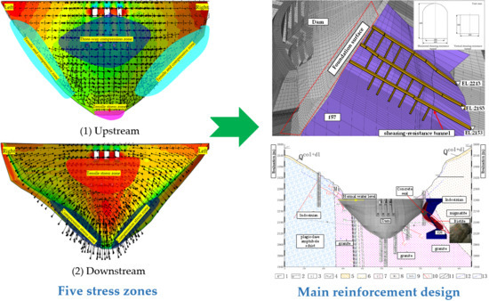
Based on past analytical experience and the analysis of the stress, displacement, and yielding region of the Xulong arch dam, five stress zones of the arch dam are proposed as follows. Figure 14 is a schematic diagram of the five stress zones. The five stress zones can better guide the crack prevention of the arch dam.
(1) Three-way compression zone of upstream surface
This zone ranges from about 1/5 to 4/5 dam height, and the zone width is close to the height. The stress state in this zone indicates the structural state of the arch dam and it is important to control the compression stress in this zone. In general, the maximum compression stress is around the arch crown beam at 1/3 elevation of the arch dam. The compression stress results of the finite element analysis are around 6.2~8.0 MPa.
(2) Tensile and compressive zone of upstream arch abutment
The stress state may be tensile stress in the direction of both beam and arch or one of the directions is tensile stress. When upstream water pressure is considered, it is the state of double-tension single-compression or double-compression single-tension. More attention should be paid to control the tensile stress of this area to prevent cracking. The calculation results show that the tensile stress of the left arch abutment of the Xulong dam reaches 1.18 MPa of case 1. It is suggested to control the tensile stress of this area to less than 1.5 MPa when the FEM is adopted.
(3) Tensile stress zone of upstream dam heel
Based on the analysis of several super-high arch dams in China, it is suggested that the tensile stress should be strictly controlled within 1.4 MPa if the tensile stress of arch dams is based on FEM simulation. The dam heel tensile stress of the Xulong arch dam is 0.9 MPa. Although the upstream bottom joint can reduce the tensile stress of the dam heel, attention should be paid to the effect of hydraulic fracturing. The upstream bottom joint cannot affect the construction of the curtain grouting. The high tensile stress is related to the discontinuous geometric shape of the arch dam heel. The cracking of the dam heel should be paid more attention to.
(4) Compression stress zone of downstream arch abutment
This zone ranges from the bottom to the middle height of the dam. Normally, the largest compression stress is in this zone and it is important to control it. The compression stress of the left arch abutment of the Xulong dam reaches 8.88 MPa of case 10. It is suggested to control the compression stress of this zone to less than 14 MPa when the FEM is adopted.
(5) Tensile stress zone of downstream surface
The arch dam’s downstream surface between the upper to middle elevation is a tensile zone, and the tensile stress is in the direction of the beam. The tensile stress may be large here due to the pier. When the upstream water level is low, this tensile stress zone will shift to the left and right arch abutments. The results of the geomechanical model test also show that the cracking of the downstream arch abutment basically extends to the center of the dam along the normal of the foundation surface, which is the failure of the tension and shear [2].
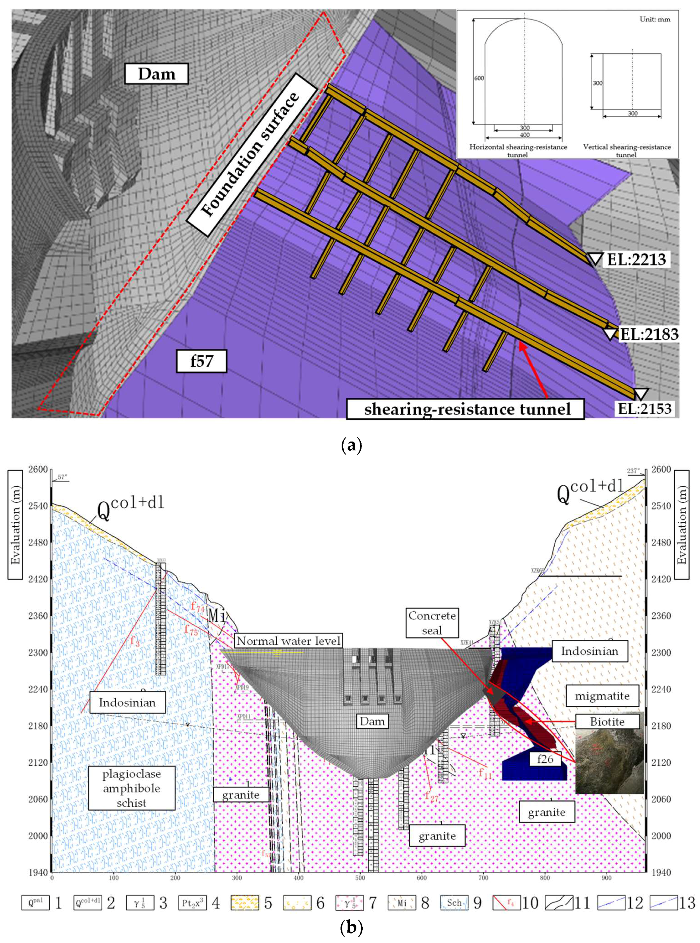
5.3. Abutment Reinforcement Suggestion
Based on the analysis of the overall stability, stress, and displacement of the arch dam, it is considered that the fault f57, xenolith, fault f26, and biotite enrichment zone have a great effect on the stress distribution of the arch abutments.
In order to improve the stress state of the dam abutments and decrease the cracking risk during long-term operation, it is recommended to use a shearing-resistance wall in the fault f57, to replace the biotite enrichment zone with concrete, and to perform consolidation grouting or anchoring on the excavated exposed weak structural zone. Figure 15 illustrates the shearing-resistance tunnel for the left arch abutment and the concrete replacement for the right arch abutment.
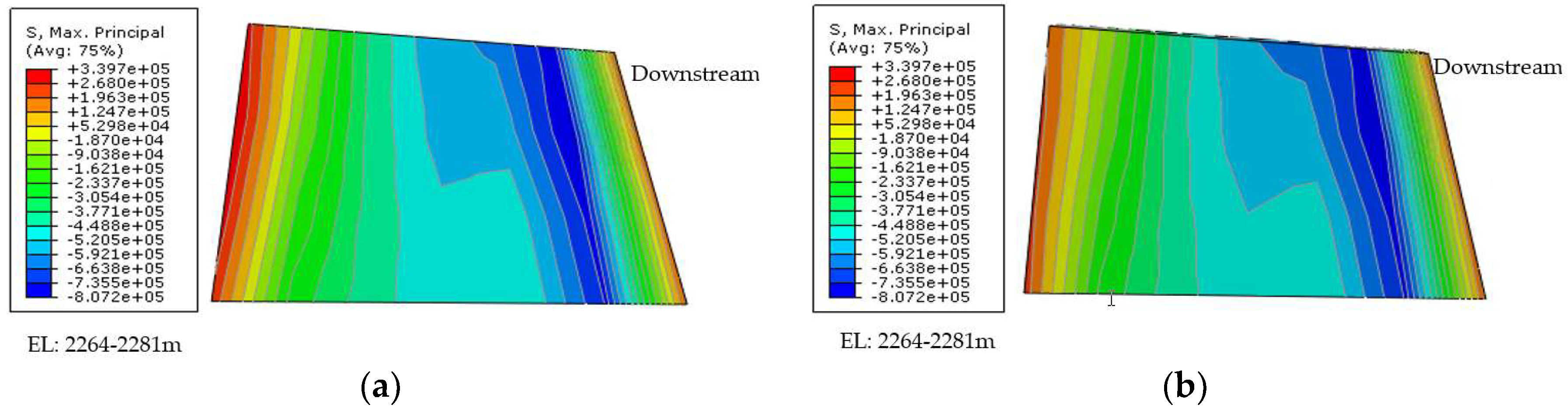
Through numerical simulation, the tensile stress and yielding zone changes of the arch abutments are obtained before and after reinforcement (Figure 16 and Figure 17). The first principal stresses of the left and right arch abutments decrease by about 0.13 and 0.17 MPa, respectively. The reinforcement of the abutments reduces the first principal stress and improves the stress state of the arch abutments, thereby reducing the cracking risk. The reinforcement method also improves the comprehensive shear strength of the side-slip surface and ensures a certain safety margin for the anti-sliding of the arch abutments.
6. Conclusions
In this paper, the different cracking types and effect factors are summarized. The cracking risk, overall stability, and abutment reinforcement of the Xulong arch dam are analyzed through numerical simulation. The following conclusions can be drawn:
- (1)
- A nonlinear constitutive model relating to the yielding region is proposed to evaluate dam cracking risk and overall stability. The temperature gradient change has a greater impact on the tensile stress and displacement of the arch dam, which increases dam cracking risk. In particular, the tensile stress of the left and right upper outlets are relatively large due to the pier.
- (2)
- The three safety factors of the Xulong arch dam are obtained, = 2~2.5; = 5; = 8.5, and the dam overall stability is guaranteed.
- (3)
- The five dam stress zones are proposed to analyze the dam cracking base of numerical results. It is recommended to use a shearing-resistance wall in the fault f57, replace the biotite enrichment zone with concrete, and perform consolidation grouting or anchoring on the excavated exposed weak structural zone. With optimal design of the dam structure according to the different stress characteristics of the five stress zones, the cracking risk and overall stability of the Xulong arch dam can be better controlled.
Author Contributions
P.L. and P.W. performed the numerical analysis on crack risk and overall stability evaluation; W.W. and H.H. provided original dam design parameters and scheme.
Funding
This research was funded by Changjiang Institute of survey, planning, design and research, China.
Conflicts of Interest
The authors declare no conflict of interest.
References
- Lin, P.; Liu, X.-L.; Hu, S.-Y.; Li, P.-J. Large deformation analysis of a high steep slope relating to the Laxiwa reservoir, China. Rock Mech. Rock Eng. 2016, 49, 2253–2276. [Google Scholar] [CrossRef]
- Lin, P.; Zhou, W.-Y.; Liu, H.-Y. Experimental study on cracking, reinforcement, and overall stability of the Xiaowan super-high arch dam. Rock Mech. Rock Eng. 2015, 48, 819–841. [Google Scholar] [CrossRef]
- Lin, P.; Shi, J.; Zhou, W.-Y.; Wang, R.-K. 3D geomechanical model tests on asymmetric reinforcement and overall stability relating to the Jinping I super-high arch dam. Int. J. Rock Mech. Min. Sci. 2018, 102, 28–41. [Google Scholar] [CrossRef]
- Duffaut, P. The traps behind the failure of Malpasset arch dam, France, in 1959. J. Rock Mech. Geotech. Eng. 2013, 5, 335–341. [Google Scholar] [CrossRef]
- Lin, P.; Liu, H.-Y.; Li, Q.-B.; Hu, H. Effects of outlets on cracking risk and integral stability of super-high arch dams. Sci. World J. 2014, 2014, 312827. [Google Scholar] [CrossRef] [PubMed]
- Xia, S.-Y.; Lu, S.-W. Approach to cracking mechanism of Kolnbrein arch dam heel. Des. Hydroelectr. Power Stn. 1999, 15, 26–33. (In Chinese) [Google Scholar]
- Zhang, X.-F.; Wang, X.-P.; Huang, Y.; Li, S.-Y. Simulation study on temperature stress of RCC arch dam under cold wave conditions. J. Water Resour. Water Eng. 2018, 29, 192–197. (In Chinese) [Google Scholar] [CrossRef]
- Zhang, X.; Liu, X.-H.; Jing, X.-Y.; Wang, Q.; Chang, X.-L. Study on effect of thermal stress compensation for MgO concrete of high arch dam in cold area. Water Resour. Power 2013, 31, 82–85. (In Chinese) [Google Scholar]
- Mirzabozorg, H.; Hariri-Ardebili, M.A.; Shirkhan, M. Impact of solar radiation on the uncoupled transient thermo-structural response of an arch dam. Sci. Iran. 2015, 22, 1435–1448. [Google Scholar]
- Liang, R.-Q. Study of thermal control and crack prevention for high arch dam in dry-hot valley region. Yangtze River 2014, 45, 42–45. (In Chinese) [Google Scholar] [CrossRef]
- Sheibany, F.; Ghaemian, M. Effects of environmental action on thermal stress analysis of Karaj concrete arch dam. J. Eng. Mech. 2006, 132, 532–544. [Google Scholar] [CrossRef]
- Maken, D.D.; Léger, P.; Roth, S.N. Seasonal thermal cracking of concrete dams in northern regions. J. Perform. Constr. Facil. 2014, 28, 04014014. [Google Scholar] [CrossRef]
- Waleed, A.M.; Jaafar, M.S.; Noorzaei, J.; Bayagoob, K.H.; Amini, R. Effect of placement schedule on the thermal and structural response of RCC dams, using finite element analysis. In Proceedings of the Geo Jordan Conference 2004, Irbid, Jordan, 12–15 July 2004; pp. 94–104. [Google Scholar] [CrossRef]
- Jia, J.-S.; Li, X.-Y. Dam heel cracking problem in high arch dams and new measure for solution. J Hydraul. Eng. 2008, 39, 1183–1188. (In Chinese) [Google Scholar] [CrossRef]
- Lin, P.; Chen, X.; Zhou, W.-Y.; Yang, R.-Q.; Wang, R.-K. Simulation on back analysis of Shuanghe arch dam cracking. Rock Soil Mech. 2003, 24, 53–56. (In Chinese) [Google Scholar] [CrossRef]
- Câmara, R.J. A method for coupled arch dam-foundation-reservoir seismic behaviour analysis. Earthq. Eng. Struct. Dyn. 2000, 29, 441–460. [Google Scholar] [CrossRef]
- Lotfi, V.; Espandar, R. Seismic analysis of concrete arch dams by combined discrete crack and non-orthogonal smeared crack technique. Eng. Struct. 2004, 26, 27–37. [Google Scholar] [CrossRef]
- Hariri-Ardebili, M.A.; Seyed-Kolbadi, S.M. Seismic cracking and instability of concrete dams: Smeared crack approach. Eng. Fail. Anal. 2015, 52, 45–60. [Google Scholar] [CrossRef]
- Mi, Y.; Aliabadi, M.H. Dual boundary element method for three-dimensional fracture mechanics analysis. Eng. Anal. Bound. Elem. 1992, 10, 161–171. [Google Scholar] [CrossRef]
- Gerstle, W.H.; Ingraffea, A.R.; Perucchio, R. Three-dimensional fatigue crack propagation analysis using the boundary element method. Int. J. Fatigue 1988, 10, 187–192. [Google Scholar] [CrossRef]
- Lubliner, J.; Oliver, J.; Oller, S.; Onate, E. A plastic-damage model for concrete. Int. J. Solids Struct. 1989, 25, 299–326. [Google Scholar] [CrossRef]
- Lee, J.; Fenves, L.G. Plastic-damage model for cyclic loading of concrete structures. J. Eng. Mech. 1998, 124, 892–900. [Google Scholar] [CrossRef]
- Feng, L.M.; Pekau, O.A.; Zhang, C.H. Cracking analysis of arch dams by 3D boundary element method. J. Struct. Eng. 1996, 122, 691–699. [Google Scholar] [CrossRef]
- Chen, J.; Soltani, M.; An, X. Experimental and numerical study of cracking behavior of openings in concrete dams. Comput. Struct. 2005, 83, 525–535. [Google Scholar] [CrossRef]
- Sharan, S.K. Efficient finite element analysis of hydrodynamic pressure on dams. Comput. Struct. 1992, 42, 713–723. [Google Scholar] [CrossRef]
- Sato, H.; Miyazawa, S.; Yatagai, A. Thermal crack estimation of dam concrete considering the influence of autogenous shrinkage. In Proceedings of the 10th International Conference on Mechanics and Physics of Creep, Shrinkage, and Durability of Concrete and Concrete Structures (CONCREEP), Vienna, Austria, 21–23 September 2015; pp. 1289–1298. [Google Scholar] [CrossRef]
- Chow, W.-Y.; Yang, R.-Q. Determination of stability of arch dam abutment using finite element method and geomechanical models. In Proceedings of the 4th Australia—New Zealand Conference on Geomechanics, Perth, Australia, 14–18 May 1984; Volume 2, pp. 595–600. [Google Scholar]
- Zhou, W.-Y.; Yang, R.-Q.; Liu, Y.-R.; Lin, P. Research on geomechanical model of rupture tests of arch dams for their stability. J. Hydroelectr. Eng. 2005, 24, 53–58. (In Chinese) [Google Scholar] [CrossRef]
- Kou, X.-D.; Zhou, W.-Y. The application of element-free method to approximate calculation of arch dam crack propagation. J. Hydraul. Eng. 2000, 31, 28–35. (In Chinese) [Google Scholar]
- Portela, A.; Aliabadi, M.H.; Rooke, D.P. The dual boundary element method: Effective implementation for crack problems. Int. J. Numer. Methods Eng. 2010, 33, 1269–1287. [Google Scholar] [CrossRef]
- Singhal, A.C.; Nuss, L.K. Cable anchoring of deteriorated arch dam. J. Perform. Constr. Facil. 1991, 5, 19–36. [Google Scholar] [CrossRef]
- Hariri-Ardebili, M.A.; Saouma, V.E. Single and multi-hazard capacity functions for concrete dams. Soil Dyn. Earthq. Eng. 2017, 101, 234–249. [Google Scholar] [CrossRef]
Figure 1.
Distribution of hydropower resources and super-high arch dams in China.

Figure 2.
Cracking type of arch dam: (a) dam heel crack; (b) dam toe crack; (c) transverse joint open; (d) horizontal cracks at the upstream surface; (e) cracks at the downstream surface; (f) internal cracks.
Figure 2.
Cracking type of arch dam: (a) dam heel crack; (b) dam toe crack; (c) transverse joint open; (d) horizontal cracks at the upstream surface; (e) cracks at the downstream surface; (f) internal cracks.

Figure 3.
Overloading and strength reduction method. (a) Increasing the bulk density of the upstream water; (b) increasing the upstream water level; (c) strength reduction method.
Figure 3.
Overloading and strength reduction method. (a) Increasing the bulk density of the upstream water; (b) increasing the upstream water level; (c) strength reduction method.

Figure 4.
Surface fault statistics in dam site area. (a) Rose of the strike; (b) rose of dip; (c) dip angle histogram.
Figure 4.
Surface fault statistics in dam site area. (a) Rose of the strike; (b) rose of dip; (c) dip angle histogram.
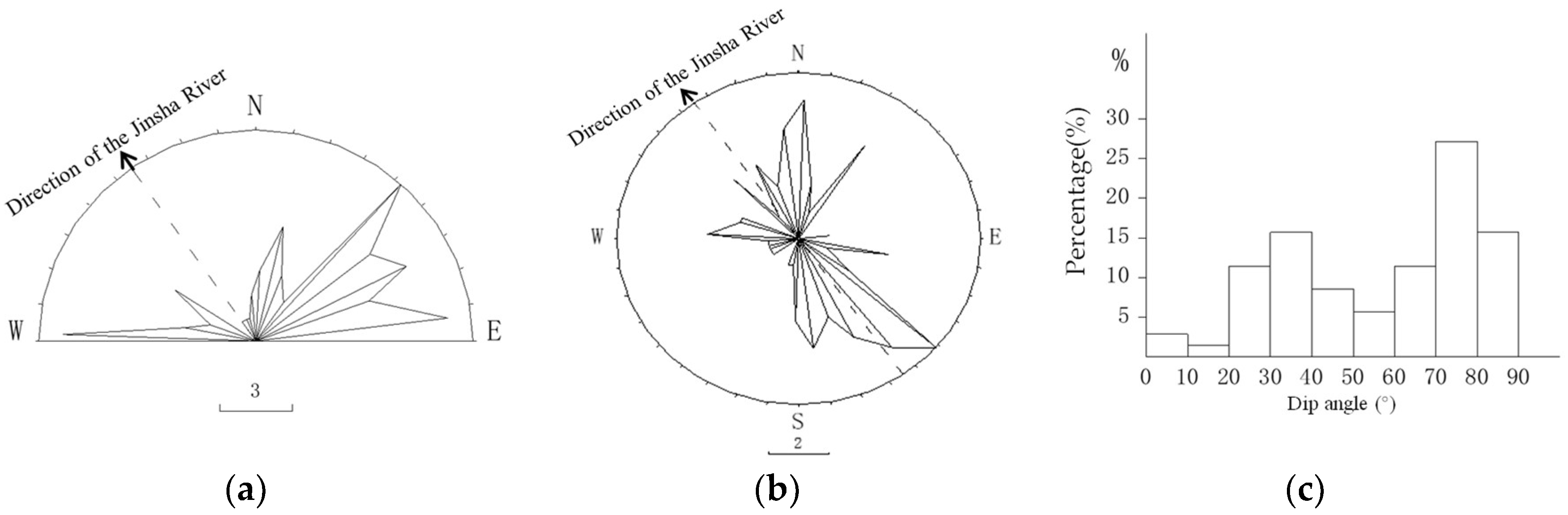
Figure 5.
Bedrock distribution of the foundation surface.

Figure 6.
The 3D numerical model. (a) dam-foundation overall model; (b) main faults distribution.

Figure 7.
The first principal stress and the displacement along the river direction distribution under analysis cases 1 & 10. (a) The first principal stress distribution under analysis case 1 (Unit: Pa); (b) the displacement along the river distribution under analysis case 1 (Unit: mm); (c) the first principal stress distribution under analysis case 10 (Unit: Pa); (d) the displacement along the river distribution under analysis case 10 (Unit: mm).

Figure 8.
The first and third principal stress distribution and possible cracking positions of outlets under analysis case (Unit: Pa). (a) The first principal stress distribution of upper outlets; (b) the third principal stress distribution of upper outlets; (c) possible crack positions of the middle upper outlet; (d) possible crack positions of the side upper outlet; (e) the first principal stress distribution of middle outlets; (f) the third principal stress distribution of middle outlets.

Figure 9.
Complex geological condition of the Xulong arch abutments. (a) Left arch abutment of the model; (b) right arch abutment of the model; (c) left arch abutment of the site (the foundation face has not been excavated); (d) right arch abutment of the site (the foundation face has not been excavated).

Figure 10.
The capacity curve of the maximum displacement along river direction of the arch crown.

Figure 11.
The yielding region under different analysis cases (PEMAG: plastic strain magnitude). (a) Downstream surface under case 8; (b) foundation surface under case 8; (c) downstream surface under case 9; (d) foundation surface under case 9.
Figure 11.
The yielding region under different analysis cases (PEMAG: plastic strain magnitude). (a) Downstream surface under case 8; (b) foundation surface under case 8; (c) downstream surface under case 9; (d) foundation surface under case 9.

Figure 12.
Crown displacement under various analysis cases 1 to 6. (a) Crown displacement along river direction; (b) crown displacement cross river direction.
Figure 12.
Crown displacement under various analysis cases 1 to 6. (a) Crown displacement along river direction; (b) crown displacement cross river direction.

Figure 13.
The distribution characteristics of arch thrust of several high arch dams. (a) Right arch abutment thrust; (b) left arch abutment thrust.
Figure 13.
The distribution characteristics of arch thrust of several high arch dams. (a) Right arch abutment thrust; (b) left arch abutment thrust.
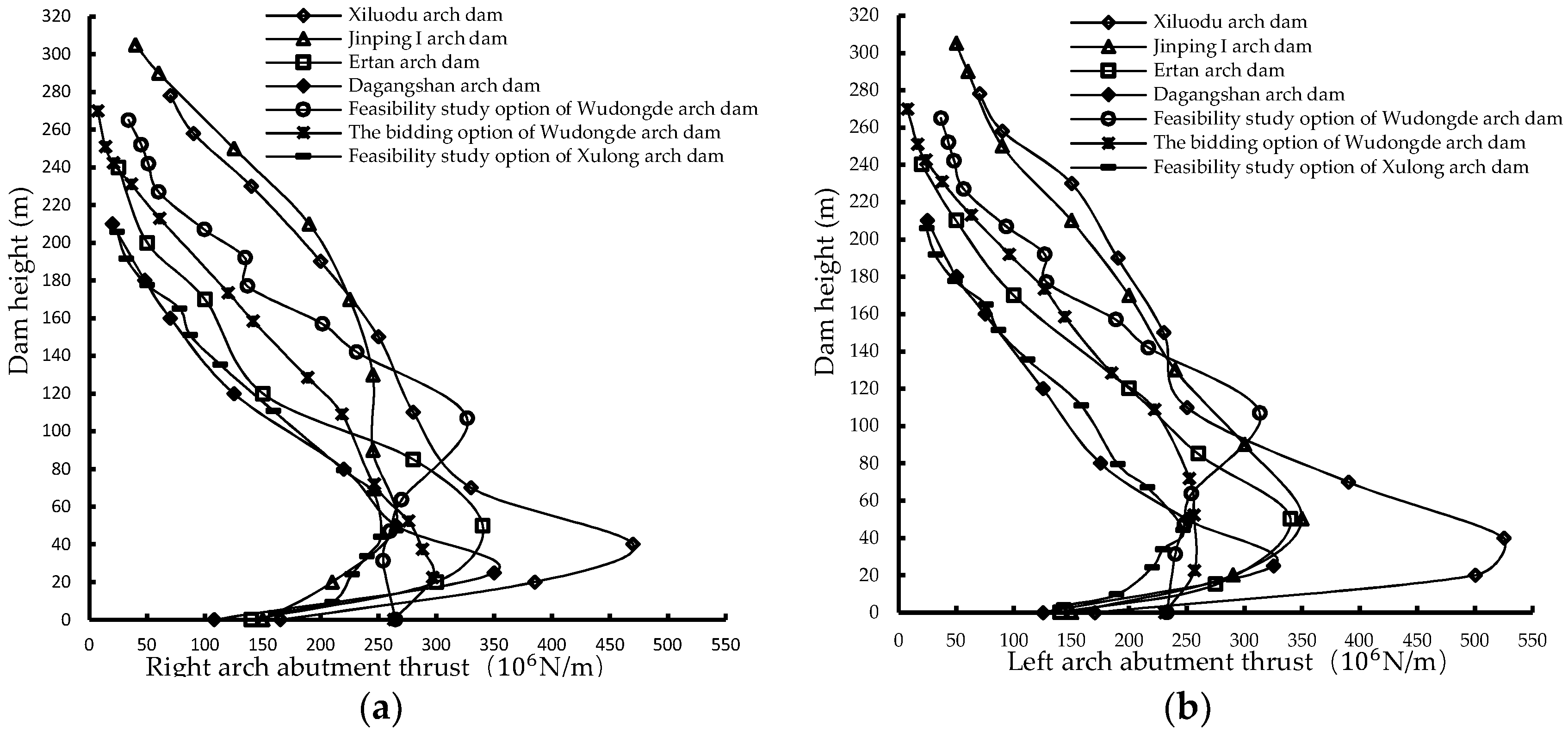
Figure 14.
Five stress zones of high arch dam. (a) Upstream surface; (b) Downstream surface. Note: The number 1–5 represents compression zone of upstream surface, tensile and compressive zone of upstream arch abutment, tensile stress zone of upstream dam heel, compression stress zone of downstream arch abutment, and tensile stress zone of downstream surface, respectively.

Figure 15.
The abutments reinforcement method of the Xulong arch dam. (a) Shearing-resistance tunnel for the left abutment; (b) concrete replacement for the right abutment.
Figure 15.
The abutments reinforcement method of the Xulong arch dam. (a) Shearing-resistance tunnel for the left abutment; (b) concrete replacement for the right abutment.

Figure 16.
The first principal stress at the right arch abutment from EL 2264 m to 2281 m (Unit: Pa). (a) Before reinforcement; (b) after reinforcement.
Figure 16.
The first principal stress at the right arch abutment from EL 2264 m to 2281 m (Unit: Pa). (a) Before reinforcement; (b) after reinforcement.

Figure 17.
The first principal stress and yielding region distribution of the left abutment (Stress unit: Pa. PEMAG: plastic strain magnitude). (a) before concrete replacement; (b) after concrete replacement; (c) before concrete replacement; (d) after concrete replacement.
Figure 17.
The first principal stress and yielding region distribution of the left abutment (Stress unit: Pa. PEMAG: plastic strain magnitude). (a) before concrete replacement; (b) after concrete replacement; (c) before concrete replacement; (d) after concrete replacement.


Table 1.
Summary of cracking types in high arch dams.
| Dam Name | Country | Operation Year | Height (m) | Cracking Description | Main Cracking Causes |
|---|---|---|---|---|---|
| Buffalo Bill Arch Dam | America | 1910 | 107.0 | Vertical cracks at downstream surface | Temperature (extreme thermal gradients) |
| Packard Sama Dam | America | 1928 | 113.0 | Different settlement | Earthquake |
| Stewart Mountain Dam [31] | America | 1930 | 64.6 | Visible surface, mainly upstream surface | Alkali–silica reactions and expansions |
| Zeuzier Dam | Switzerland | 1956 | 156.0 | Transverse joints open at upstream Peripheral joints form downstream | Foundation |
| Sardine Dam | Italy | 1957 | 115.0 | Horizontal cracks at upstream surface | Temperature |
| Santa Maria Dam | Switzerland | 1968 | 117.0 | Leakage in dam foundation upstream | Foundation |
| Daniel Johnson Dam [12] | Canada | 1968 | 214.0 | Oblique cracks at downstream surface | Seasonal temperature |
| Plunging cracks at the heel of the dam | Geometric discontinuities | ||||
| Kolnbrein Dam [6,14] | Austria | 1977 | 200.0 | Horizontal construction joints open Cracking at dam heel | Foundation |
| Zillergrundl Dam [14] | Austria | 1985 | 186 | Horizontal cracks at heelVertical cracks in the elevator shaft | Concrete hydration heat |
| Sayano-Shushenskaya Dam [14] | Former Soviet Union | 1989 | 242.0 | Vertical cracks in the gallery Horizontal cracks at upstream surface | Concrete hydration heat and temperature |
| Shuanghe Arch Dam [15] | China | 1991 | 82.3 | Seven vertical cracks at downstream surface | Self-weight and weak foundation |
| Ertan Dam | China | 2000 | 240.0 | Cracking at downstream surface | Foundation Temperature |
| Xiaowan Dam [2] | China | 2010 | 294.5 | Internal cracking | Temperature |
| Goupitan Dam | China | 2011 | 232.5 | Cracking around the bottom outlets | Concrete hydration heat and temperature |
Table 2.
Physical–mechanical parameters of the rock masses and dam materials.
| Materials | Bulk Density (t/m3) | Deformation Modulus (GPa) | Poisson’s Ratio | Shear Strength | |
|---|---|---|---|---|---|
| C′ (MPa) | F′ | ||||
| Dam concrete | 2.40 | 25.0 | 0.167 | 5.0 | 1.7 |
| Rock of type II | 2.70 | 24.0 | 0.22 | 1.2 | 1.1 |
| Rock of type III1 | 2.60 | 17.5 | 0.24 | 1.05 | 1.0 |
| Rock of type III2 | 2.55 | 12.5 | 0.26 | 1.0 | 0.95 |
| Rock of type IV | 2.50 | 6.0 | 0.30 | 0.65 | 0.60 |
Table 3.
The mean and linear temperature difference under normal water level.
| Normal Water Level + Temperature Rise | Normal Water Level + Temperature Drop | |||
|---|---|---|---|---|
| EL (m) | Mean Temperature Difference | Linear Temperature Difference | Mean Temperature Difference | Linear Temperature Difference |
| 2308 | 9.40 | 0.00 | 2.65 | 0.00 |
| 2302 | 7.67 | 3.09 | 3.22 | −0.49 |
| 2290 | 4.75 | 8.65 | 2.06 | 2.06 |
| 2270 | 2.42 | 12.54 | 0.68 | 5.67 |
| 2245 | 2.24 | 14.18 | 0.92 | 7.99 |
| 2220 | 2.79 | 14.66 | 1.67 | 8.98 |
| 2195 | 3.60 | 14.85 | 2.62 | 9.29 |
| 2170 | 3.58 | 14.72 | 2.65 | 9.45 |
| 2145 | 1.43 | 9.96 | 0.83 | 6.53 |
| 2120 | −0.97 | 4.74 | −1.35 | 2.60 |
| 2095 | −1.88 | 2.66 | −2.12 | 1.32 |
Table 4.
Characteristic stresses at different key locations under analysis cases 1 & 10 (unit: MPa).
Table 4.
Characteristic stresses at different key locations under analysis cases 1 & 10 (unit: MPa).
| Location | Content | Case 1 | Case 2 |
|---|---|---|---|
| Upstream surface | Maximum tensile stress of dam heel | 0.9 | 0.89 |
| Maximum tensile stress near left arch abutment | 1.18 | 1.17 | |
| Maximum tensile stress near right arch abutment | 0.97 | 0.94 | |
| Downstream surface | Maximum compression stress of dam toe | 6.93 | 7.35 |
| Maximum compression stress near left arch abutment | 8.76 | 8.88 | |
| Maximum compression stress near right arch abutment | 8.53 | 8.49 |
Table 5.
Maximum displacement along river direction at different key locations under analysis cases 1 & 10.
Table 5.
Maximum displacement along river direction at different key locations under analysis cases 1 & 10.
| Case 1 | Case 10 | |||||
|---|---|---|---|---|---|---|
| Left Arch Abutment | Arch Crown | Right Arch Abutment | Left Arch Abutment | Arch Crown | Right Arch Abutment | |
| Maximum (mm) | 6.55 | 32.9 | 5.04 | 8.29 | 20.2 | 5.98 |
| EL (m) | 2167.3 | 2308 | 2153 | 2167.3 | 2263 | 2153 |
© 2018 by the authors. Licensee MDPI, Basel, Switzerland. This article is an open access article distributed under the terms and conditions of the Creative Commons Attribution (CC BY) license (http://creativecommons.org/licenses/by/4.0/).
Share and Cite
MDPI and ACS Style
Lin, P.; Wei, P.; Wang, W.; Huang, H. Cracking Risk and Overall Stability Analysis of Xulong High Arch Dam: A Case Study. Appl. Sci. 2018, 8, 2555. https://doi.org/10.3390/app8122555
AMA Style
Lin P, Wei P, Wang W, Huang H. Cracking Risk and Overall Stability Analysis of Xulong High Arch Dam: A Case Study. Applied Sciences. 2018; 8(12):2555. https://doi.org/10.3390/app8122555
Chicago/Turabian StyleLin, Peng, Pengcheng Wei, Weihao Wang, and Hongfei Huang. 2018. "Cracking Risk and Overall Stability Analysis of Xulong High Arch Dam: A Case Study" Applied Sciences 8, no. 12: 2555. https://doi.org/10.3390/app8122555
Note that from the first issue of 2016, this journal uses article numbers instead of page numbers. See further details here.