Article

An Analysis of Angular Indexing Error of a Gear Measuring Machine

1
Key Laboratory for Precision and Non-traditional Machining of Ministry of Education, Dalian University of Technology, Dalian 116023, China
2
Department of Mechanical Engineering, National Taiwan University, Taipei 10617, Taiwan
*
Author to whom correspondence should be addressed.
Appl. Sci. 2018, 8(2), 169; https://doi.org/10.3390/app8020169
Submission received: 1 November 2017 / Revised: 16 January 2018 / Accepted: 22 January 2018 / Published: 25 January 2018
(This article belongs to the Section Mechanical Engineering)

Abstract

:

Featured Application

The method introduced in the paper can be applied to, and can increase angular indexing accuracy of, all machines equipped with a mandrel to rotate the workpiece, such as gear measuring machines (GMMs), gear grinding machines, polygon grinding machines, cam grinding, and measuring machines.

Abstract

In gear measuring machines (GMMs), the tested gear is mounted on a mandrel, which is pivoted at both ends by two centers in a vertical arrangement. The upper center is fixed and the lower center is driven by the spindle of rotation. The coaxiality error between the central line of the mandrel and the spindle average line of a GMM always exists in terms of the offset and angle measured in one plane. Such a coaxiality error would cause an angular indexing error of tested gear resulting in measurement error. This phenomenon has rarely been investigated. In this paper, a GMM is taken as an example and its coaxiality error of the mandrel and spindle error of the rotary stage are measured. The difference of rotated angles between the mandrel and spindle is theoretically analyzed by derived formulae. Calibrated by a precision polygon and an autocollimator, the predicted angular index error of the mandrel was consistent with experimental results. Through the experimental verification, it was found that, when the coaxial deviation between the two centers was 10 μm and the lower center tip’s radial motion error was 1.6 μm, the angular indexing deviation of the mandrel was ±5″. If the errors were compensated according to the analyzed model, the residual error was reduced to ±2″. A significant improvement in the angular positioning accuracy of the GMM can be achieved.

1. Introduction

The method of mounting the workpiece onto a mandrel and rotating the mandrel by a two-center pivotal clamp to achieve angular positioning of the workpiece has been widely used in many machines, such as gear and cam grinding and measuring machines. One center is to be clamped and rotated by the spindle of a rotary table, and the other center is normally fixed to the rail. In an ideal case, the mandrel is coaxial, and the spindle axis and the spindle is in pure rotation. In real cases, however, due to manufacturing and assembly errors, both the spindle and the mandrel have certain inevitable systematic errors. On one hand, the spindle has inherent geometric errors in six degrees of freedom (6-DOF), as mentioned in ISO230-1, ISO230-7, and ASME B89.3.4 [1,2,3] as well as in the book by Marsh [4], which includes three translational errors and three rotational errors. On the other hand, the mandrel has inherent coaxiality errors with respect to the spindle axis due to misalignment of the two centers. All these errors induce an angular positioning error of the workpiece, resulting in dimensional error or measurement error. In the past, many researchers studied the techniques of multi-degree-of-freedom measurement (MDFM) on the geometric errors of the rotary stage. Liu developed the error motion and the angular indexing measuring devices using position sensitive detectors (PSDs) and diffraction grating [5]. Jywe established a novel technique using diffractive grating and PSDs to calibrate the 4-DOF errors of a rotary table [6]. Sung proposed a new measurement system based on a laser diode, PSDs, and a homogeneous transformation approach to separately measure six geometric errors of a rotary axis [7]. He et al. proposed a method of using a dual optical path measurement method (DOPMM) to identify all 6-DOF errors of a rotary stage one by one [8]. Zhang proposed a novel measuring method for geometric error identification of the rotary table on five axis machine tools using a double ball bar [9]. Akategawa proposed concentric circle grating and phase modulation interferometers to achieve concurrent measurement of all 6-DOFerrors of a rotary table [10]. Evans et al. expressed a general methodology of self-calibration in dimensional metrology using a reversal or error separation method, including the spindle errors [11].
Although many methods for measuring the error motions of spindles or rotary tables have been investigated, the angular positioning error caused by the coaxility error of two cascade axes of rotation has not been paid much attention. Previous studies by Lou et al. on gear measurement were on a specially designed test rig, called a double-disc instrument, for measuring the involute profile [12,13]. For the pitch measurement on a commercial gear measuring machine (GMM), Lou et al. used a multi-step method to measure the pitch deviation of the gear [14]. Liu et al. considered the offset of the probing position due to alignment error of the gear axis (same as the mandrel axis in this report) and proposed a method to compensate the induced pitch deviation in measurement [15]. It is quite close to the goal of this study, but they only verified the error model by computer simulation and neglected error motions of the rotating shaft. It is known that the radial motion and tilt of the spindle will cause an angular positioning error at the rotary stage [16]. Here, not only the coaxiality and spindle errors but also the angular positioning error of the rotary table of an investigated GMM was measured. Their influences on the angular positioning error of the mandrel at the gear measuring plane was theoretically derived. This theoretically predicated error was validated by experimental results. It was found that the measurement accuracy of any GMM can be largely improved after the predicted angular positioning error is compensated.

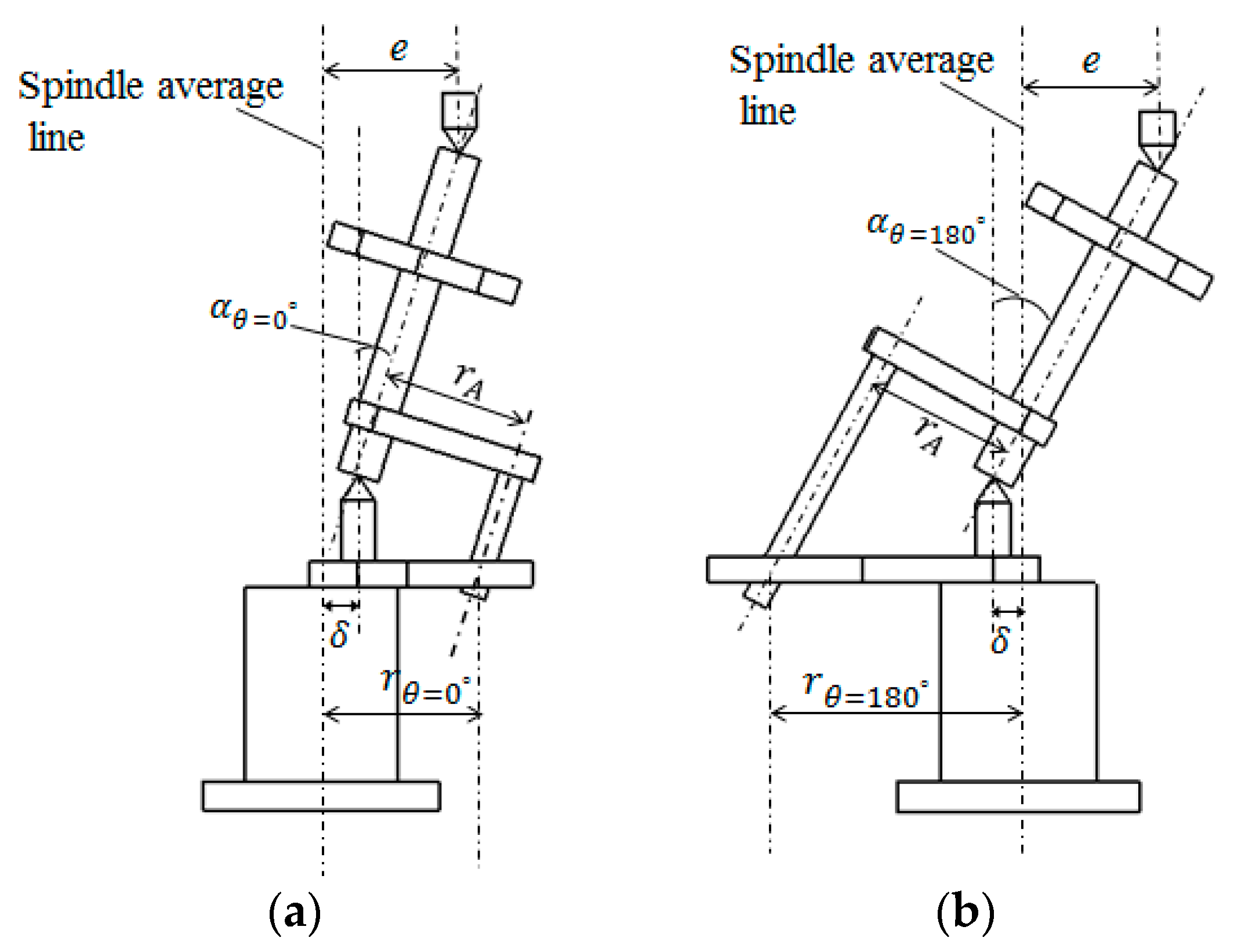
2. Angular Indexing Errors Caused by the Coaxial Deviation of the Mandrel

Figure 1 shows the configuration of a GMM, model 891E (Mahr Company, Göttingen, Germany). The gear to be measured is mounted onto a mandrel, whose two ends are pivoted by an upper center and a lower center, respectively. In this figure, the gear is replaced by a polygon to test the actual angle of rotation. The upper center is fixed to the rail of the column, and the lower center is driven by the spindle of the rotary stage. A clamping module, including the fixture, connecting rod, and plate, tightly fixes the mandrel to the lower center so that all these parts rotate together as a rigid body. When the spindle rotates, the mandrel is simultaneously rotated. The angle of rotation is measured by an encoder underneath the spindle inside the rotary stage. This is the ideal case without any errors mentioned in the last section.
Figure 2 shows a schematic diagram of the actual case and shows that the spindle has radial run-out and tilt with respect to the ideal axis of rotation. The mandrel has a coaxiality error with respect to the ideal spindle axis. The spindle errors are generated from the bearing plane from which the radial error motion and tilt error motion of the shaft, or spindle, start [16]. It is obvious that the mandrel will rotate around a cone contour because the tip of the lower center has radial run-out error motion due to combined error sources at the tip’s height. This kind of machine has not only spindle errors but also the mandrel’s coaxiality error. The actual rotated angle of the mandrel must be deviated from the reading of the encoder. This is the main goal of this study to investigate the difference in between.
For simplicity to explain, the coaxiality error and the spindle error are considered separately. Considering that the spindle average line is the same as its ideal axis of rotation and the mandrel average line is the same as it center line, a simplified illustration of coaxial error can be seen in Figure 3, including two angle states of the spindle rotation at 0° and 180°, respectively. It assumes the upper center is off the spindle average line by a distance of e. The moving parts, including the mandrel, polygon, and the clamping module, will be driven to rotate by the spindle.
As shown in Figure 3, e is the radial coaxiality error of the mandrel to the spindle average line and α is the tilt angle. r θ is the variable radius of the contact point between the connecting rod and the plate while rotating. Let the minimum and maximum values of r θ be r θ = 0° and r θ = 180°, respectively. From the geometrical relationship, Equations (1) and (2) can be obtained.
r θ = 0 ° = A B A O = r A cos α h tan α
r θ = 180 ° = A B + A O = r A cos α + h tan α
where L is the length of the mandrel between two centers, r A is the distance between the mandrel and connecting rod, and h is the height of the lower center from the table top. Since r θ varies in a sinusoidal form during rotation with a maximum at θ = 180° and a minimum at θ = 0°, it can be expressed by
r θ = ( r θ = 180 ° + r θ = 0 ° ) 2 ( r θ = 180 ° r θ = 0 ° ) 2 cos θ .
Substituting Equations (1) and (2) into (3), where α is a very small angle, Equation (3) can be simplified to
r θ = r A h tan α cos θ .
Let the angular velocity of the spindle be ω and the mandrel be ω A . The velocity of the contact point between the plate and the connecting rod can be obtained either from the mandrel or the spindle.
ω r θ = ω A r A .
The rotational angle of the mandrel is the time integration of its angular velocity.
θ A = 0 t ω A d t = 0 t r θ r A ( ω d t ) .
Substituting Equation (4) into (6), the relationship between rotational angle of spindle and mandrel can be obtained.
θ A = θ + ( h tan α r A ) sin θ .
Therefore, the angular difference between the mandrel and the spindle, when the mandrel has coaxial deviation from the spindle axis, can be theoretically obtained as
Δ θ = θ A θ = ( h tan α r A ) sin θ
where
tan α = e L 2 e 2 .

3. Angular Indexing Error Caused by Coaxiality Error of Mandrel and Radial Error of Spindle

In the GMM, the upper center is fixed and the lower center rotates with the spindle. As given in Figure 1, the tip of the lower center will experience radial motion due to the spindle error in tilt and radial motion. Figure 4 shows the off-axis radial position of the lower center tip when the angle is at 0° and 180°, respectively. It is noted that this tip motion has combined the effects of tilt motion and radial motion of the spindle. The spindle tilt is very small and is not shown in the figure.
Let the radial error motion of the tip of lower center be denoted by δ. From the geometrical relationship of Figure 4, the angle α is varied during rotation. Let r θ be minimum when θ = 0° and maximum when θ = 180°. The following equations can be derived.
tan α θ = 0 ° = ( e δ ) L 2 ( e δ ) 2
tan α θ = 180 ° = ( e + δ ) L 2 ( e + δ ) 2
r θ = 0 ° = r A cos ( α θ = 0 ° ) h tan ( α θ = 0 ° )
r θ = 180 ° = r A cos ( α θ = 180 ° ) + h tan ( α θ = 180 ° ) .
Since r θ varies in a sinusoidal form during rotation with maximum at θ = 180° and minimum at θ = 0°, it can be expressed by
r θ = r A ( r θ = 180 ° r θ = 0 ° ) 2 cos θ .
Similar to Equation (5), the following equations can be obtained.
θ A = 0 t ω A d t = 0 t ω r θ r A d t = 0 θ r θ r A d θ = θ + ( r θ = 180 ° r θ = 0 ° ) 2 r A sin θ .
Substituting (12) and (13) into (15), the angular indexing error of the mandrel due to its coaxiality error to the spindle and the spindle error induced radial error motion of the lower center tip can be theoretically derived as
Δ θ = θ A θ = sin θ 2 r A ( h tan ( α θ = 180 ° ) + h tan ( α θ = 0 ° ) ) .
Equation (16) implies that the angular indexing error (Δθ) of the mandrel relative to the table top of the rotary stage can be theoretically analyzed as a function of e, δ, h, L, and rA, among which h, L and rA can be measured directly on the GMM. Therefore, if e and δ are obtained by experiments, Δθ can then be predicted.

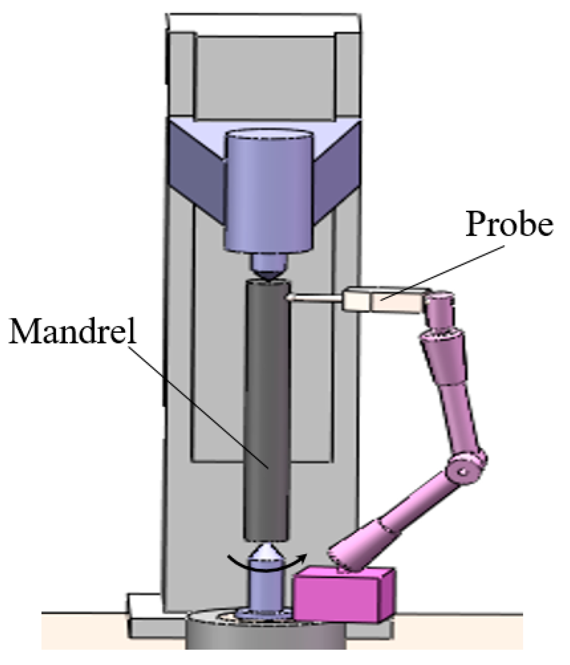
4. Experimental Verification

In order to verify the above analytical formula, experiments were carried out to measure the coaxiality error of the mandrel, the radial error motion of the lower center, and the angular indexing error of the mandrel.

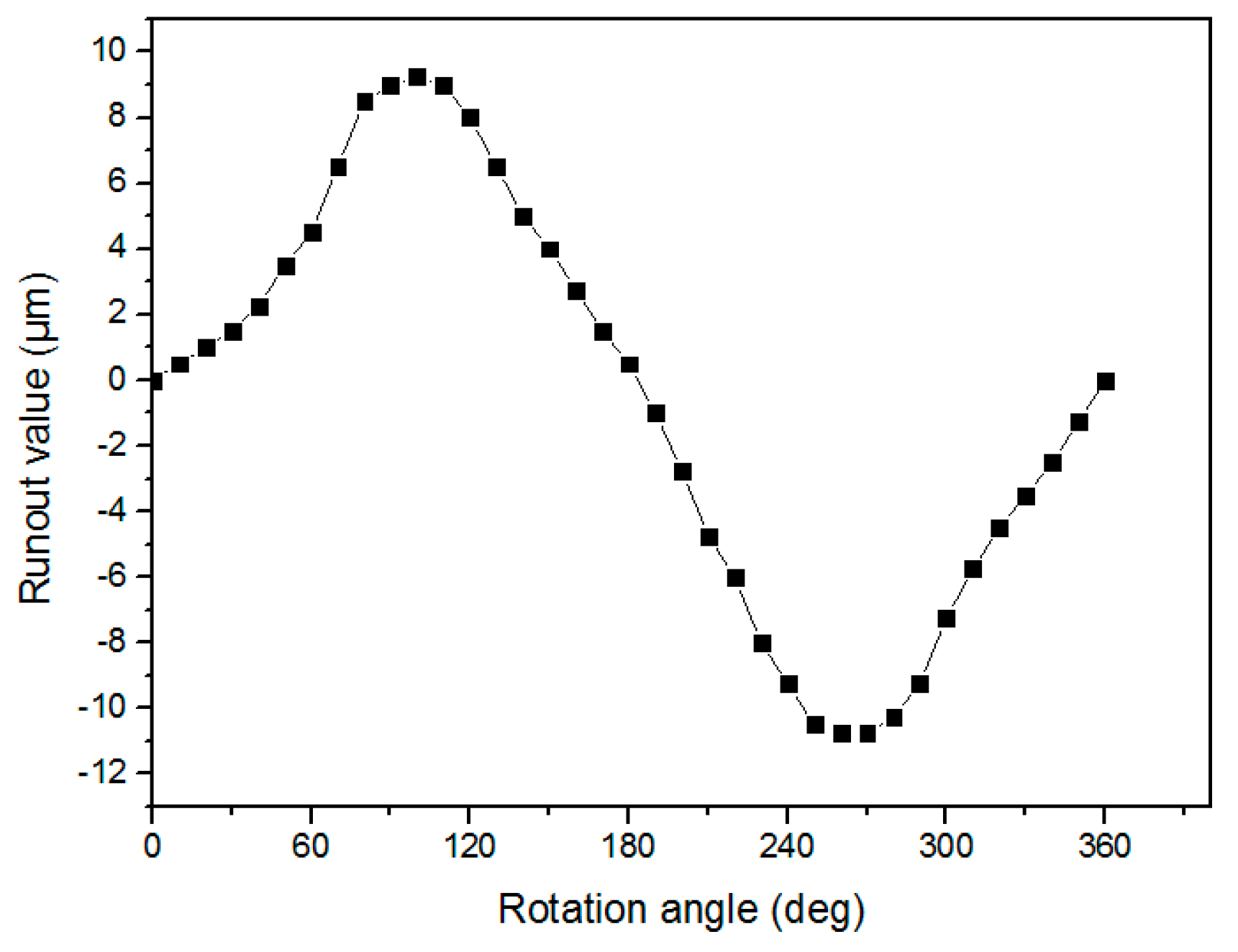
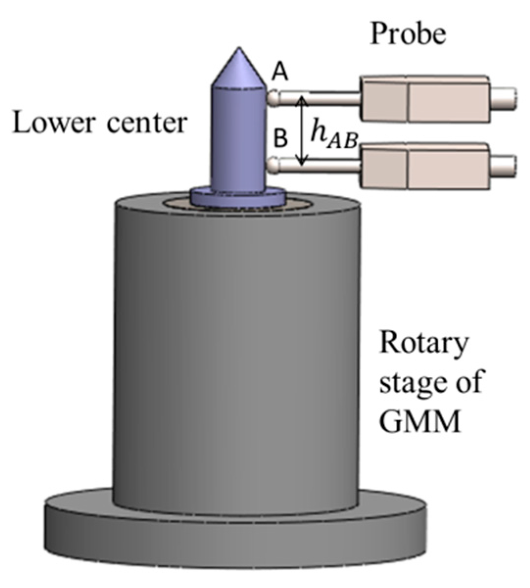
4.1. Measurement of Coaxial Deviation between Two Centers

As shown in Figure 5, an electronic probe extended from the magnetic stand was adopted for use. This probe is the type of linearly varied differential transformer (LVDT, Chungyuan Instrument Company, Sanmenxia, China, model DGB-5B, with resolution 0.1 μm, maximum indication error 0.5 μm for the selected range of ±30 μm). The magnetic stand was firmly fixed to the base of lower center, i.e., the top of rotational table, and the probe head is pointed to the mandrel at the position close to the tip of the upper center. The extension arm was sturdy enough to hold the probe when the magnetic switch was on. When the bottom stage rotated, the probe set simultaneously rotated around the mandrel. Therefore, the reading of the probe represented the relative run-out motion of the tip of the upper center to the base of the lower center, or vice versa. This is also the value of the radial coaxiality error of the mandrel to the spindle average line (denoted by “e” in Figure 4). Measured results are shown in Figure 6. The relative radial motion of the upper center with respect to the base of the lower center was about 10 μm.
As pointed out in Figure 1 that the spindle itself also has tilt and radial errors that would result in the radial motion of the tip of lower center, denoted by δ in Figure 4, during the spindle rotation. Such a radial motion has to be measured in order to verify Equation (16). Figure 7 shows the setup for measuring the radial error motion of the lower center. Two LVDTs were employed to contact two positions (A and B) of the lower center with a separation of 50 mm ( h A B ). Measured results are shown in Figure 8. There is nearly no difference between the two readings, which reflects the very small tilted error of the spindle. Therefore, the radial error motion ( δ ) of the tip of the lower center was estimated to be about 1.6 μm. In addition, the actual tilted direction on the cross-sectional plane of the spindle, called the principal axis of tilt, was not known in practice. However, it has been defined in Figure 3 and Figure 4 that the run-out value is minimum when θ = 0° and maximum when θ = 180°. Figure 8 shows that the run-out value ( r θ ) increased to about 90° and then decreased. The actual position of θ = 0°, as indicated in Figure 4a, was at θ = 90° in this experiment. This phase shift correction will be considered in a later experiment.

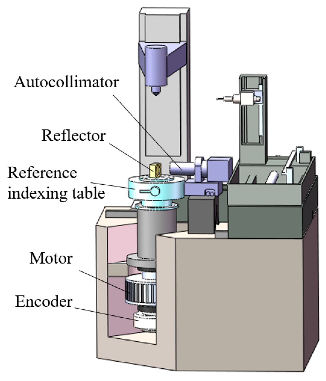
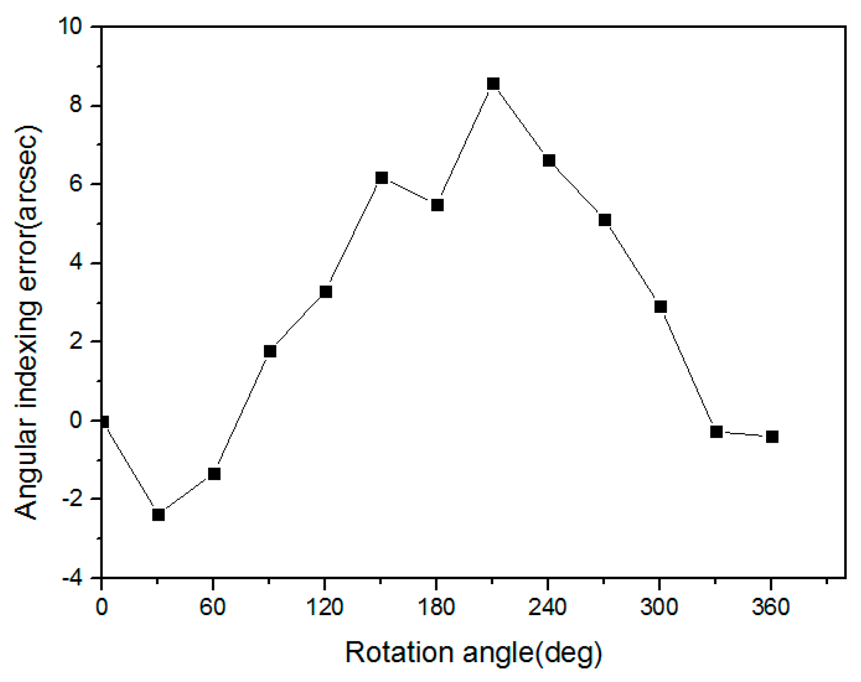
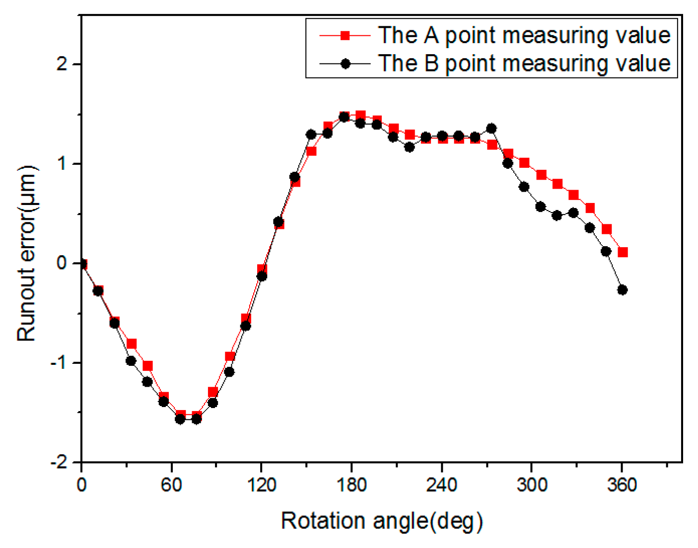
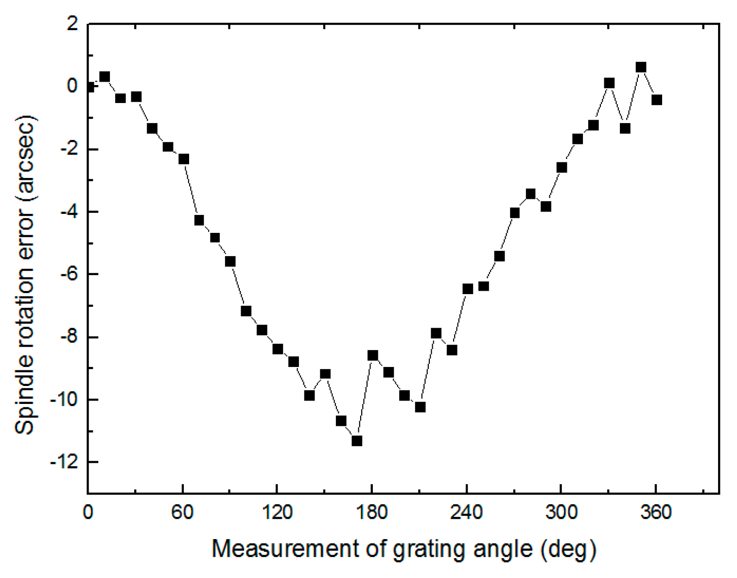
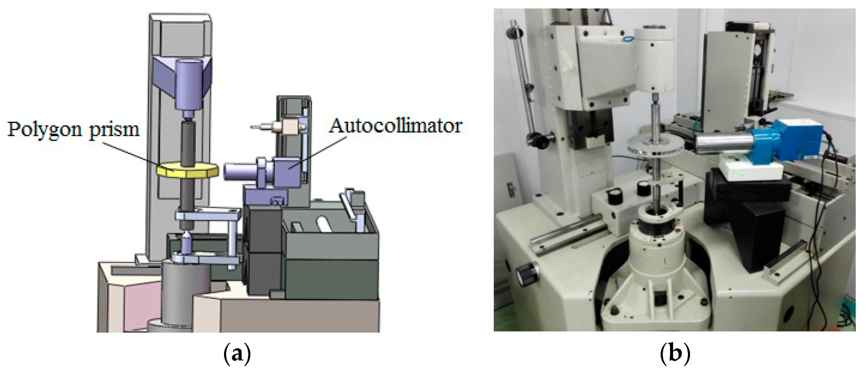
4.2. Measurement of the Angular Indexing Error of the Spindle

In a GMM, the angular position of the spindle is detected by an encoder at the bottom of the shaft. Due to the inherent 6-DOF geometric errors of the axis of rotation, the actual rotated angle of the spindle (also called the rotary stage) is different from the encoder reading [14]. Such a difference must be measured in advance for error compensation. As shown in Figure 9, a high precision multi-tooth indexing table (Jiujiang Instrument Company, Jiujiang, China, model ZDFT-720 teeth, calibrated accuracy ±0.1″, uncertainty ±0.06″) was adopted as a reference angle device. Each time the spindle rotated to a prescribed angle, the reference indexing table rotated the same angle in the reverse direction. The reflector, mounted onto the indexing table, would associate with the autocollimator (Tianjin ATMV Company, Tianjin, China, model Automat 1000UH-3050; calibrated accuracy: ±0.2″; uncertainty: ±0.1″ (k = 2)) to display the angular positioning error of the spindle. In the experiment, the spindle was rotated each time by a step size of 15° for one complete cycle. Figure 10 shows the calibrated indexing errors, called the angular positioning error, conforming to ISO230-7. The error would reset to zero when the spindle turned a full cycle. It can be seen that this spindle has a lagged phase, a maximum of −11″ at θ = 170°, and then gradually catches up. This is the angular positioning error of the rotary stage itself.

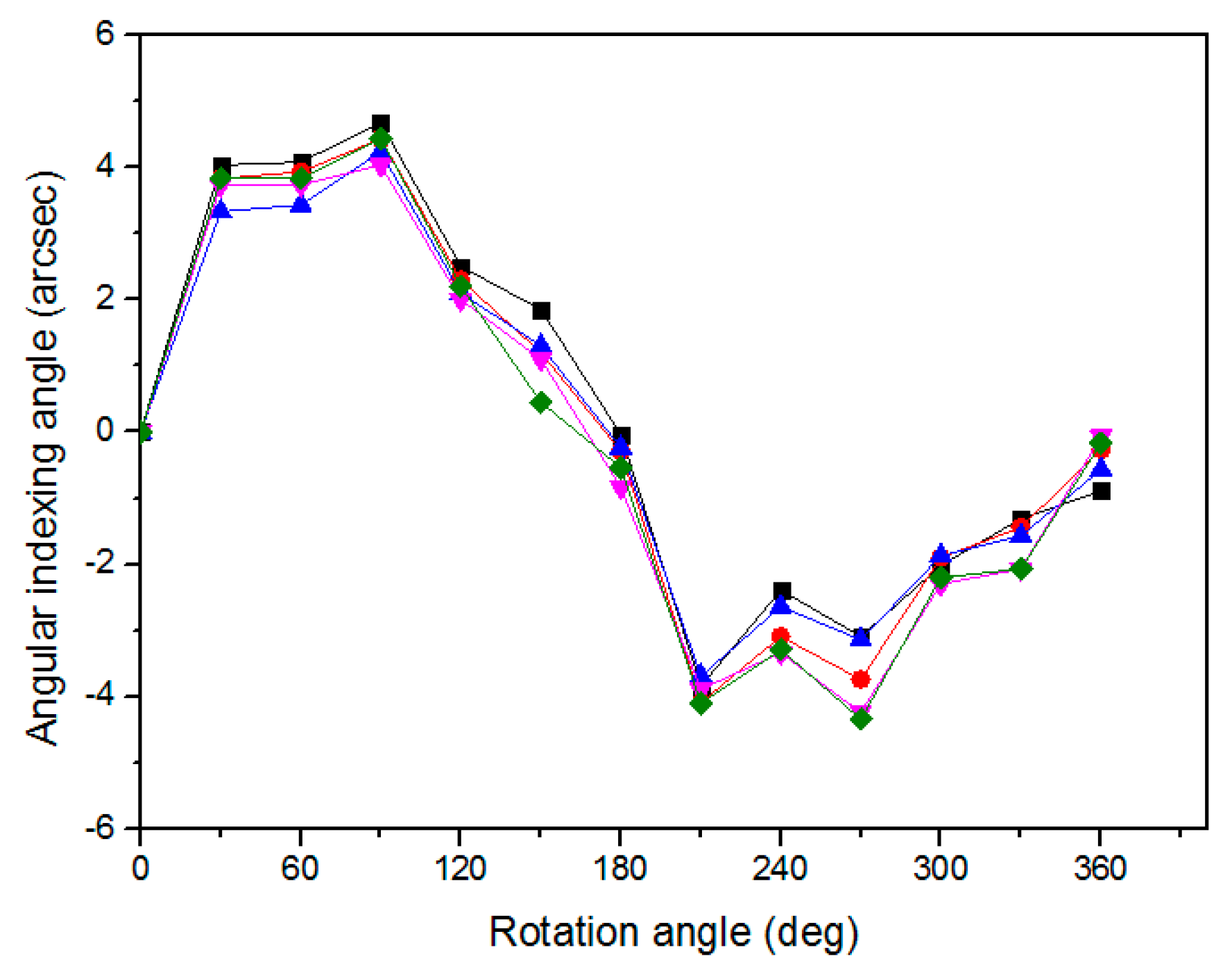
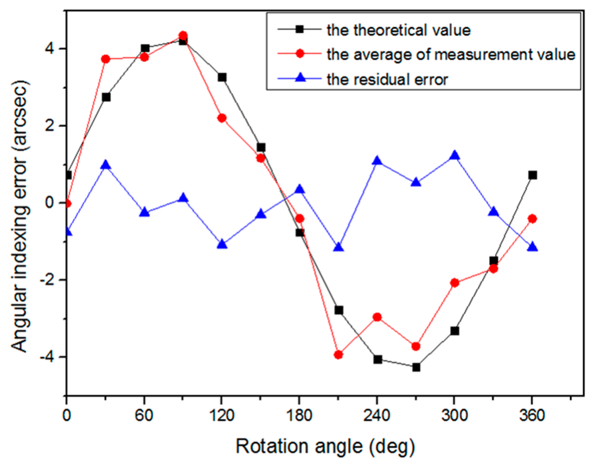
4.3. Measurement of the Angular Indexing Error of the Mandrel

In order to measure the angular indexing error of the mandrel caused by the coaxial deviation between the two centers, a 36-sided polygon was fixed to the mandrel, whose angular position error was measured by an autocollimator, as shown in Figure 11. The measured angular indexing error is cumulated angular errors from the encoder to the polygon, including (1) the angular indexing error of the spindle at the top plane of the rotary stage, as given by Figure 10 and (2) the induced angular indexing error caused by the radial error motion of the tip of the lower center and the coaxiality error of the mandrel to the spindle, as given by Equation (16). It is noted that the polygon’s angular accuracy was calibrated in advance by the above-mentioned autocollimator and the multi-tooth indexing table. Figure 12 shows the measured angular indexing error of the mandrel. It can be seen that the gear to be measured in this GMM has an angular indexing error in the range of −2–9″. Such an error will cause measurement error in the gear parameters.
Since all experiments in this study were carried out with the same starting point of the rotary stage, the prescribed starting angle of Figure 8 has a 90° shift to Figure 4. Therefore, all experimental data were shifted by 90°. The measured angular indexing errors of the gear, shown in Figure 12, have been shifted 90° in Figure 13. This experiment was conducted by five times. Table 1 lists the statistical data. The maximum difference was about 0.8″ on average and beyond 1″ at two positions only.
From Figure 6, the radial coaxiality error (e) of the mandrel was found to be 10 μm. From Figure 8, the radial error motion (δ) of the tip of the lower center was estimated to be about 1.6 μm. The theoretical angular indexing error of the mandrel relative to the table top of the rotary stage can be calculated by Equation (16). The angular indexing error of the rotary stage is shown in Figure 10. The summation of the angular indexing errors of Figure 10 and Equation (16) represents the theoretical angular indexing error of the mandrel of the GMM, as shown in Figure 14. Both curves are close to each other with residual errors within ±2″. The accuracy of theoretical analysis is thus experimentally verified.

5. Discussion

According to the analysis and experiments above, it has been proven that the angular indexing error (also called the angular positioning error) of the mandrel of a GMM can be predicted if the errors of the mandrel are known. These geometric errors can be measured by proper techniques. The measured radial error motion of the lower center contains not only the radial error of the spindle but also the centering error of the lower center. In addition, the radial error motion of the spindle only considers its first harmonic. The residual errors of the mandrel’s angular indexing errors, as shown in Figure 13, could be due to the remaining higher harmonics of the spindle’s radial errors. It is noted that these residual errors still contain the original radial error of the spindle and the tilt induced radial error at the tip of the lower center.
Although this paper presents the methodology of analyzing the angular indexing error of the GMM due to the coaxility error of the mandrel, the radial error of the lower center tip, and the angular indexing error of the spindle, it can also apply to other machines with a similar mechanism, such as a gear grinding machine, cam grinding and measuring machines, or even a long lathe.

6. Conclusions

In this report, an analytical model of predicting the angular indexing error (also called the angular positioning error) of a rotational mandrel with both ends supported by a two-center module has been developed. The main sources of error are caused by the coaxility error of the mandrel and the radial motion of the lower center. In addition, the angular positioning error of the spindle cannot be ignored. A comprehensive investigation was conducted through derived formulae and experimental verification. Since these errors are systematic, they can be used for error compensation to improve the indexing error of the mandrel. A GMM was adopted for demonstration. Through experimental verification, it was found that the angular indexing errors of the mandrel was within ±5″ when the coaxial deviation between the two centers was 10 μm, the lower center’s radial motion error was 1.6 μm, and the indexing error of the spindle was within ±5″. The difference between predicted error and measured error was within ±2″. Good agreement was thus achieved. This method can be applied to other machines with a similar structure.

Acknowledgments

This project was supported by the National Natural Science Foundation of China (U1508211, 51621064), the National Key Research and Development Program of China (2017YFF0204800), and the Fundamental Research Funds for the Central Universities (No. DUT16RC(3)034).

Author Contributions

Kuang-Chao Fan and Zhi-Feng Lou conceived and designed the experiments; Peng-Fei Xue and Yuan-Song Zheng performed the experiments; Zhi-Feng Lou and Peng-Fei Xue analyzed the data; Kuang-Chao Fan wrote the paper.

Conflicts of Interest

The authors declare no conflict of interest.

References

  1. ISO 230-1:2012 I. Test Code for Machine Tools—Part 1: Geometric Accuracy of Machines Operating under No-Load or Quasi-Static Load Conditions; ISO: Geneva, Switzerland, 2012. [Google Scholar]
  2. ISO 230-7:2006 I. Test Code for Machine Tools—Part 7: Geometric Accuracy of Axes of Rotation; ISO: Geneva, Switzerland, 2006. [Google Scholar]
  3. ANSI/ASME B89.3.4-2010. Axes of Rotation: Methods for Specifying and Testing; ASME: New York, NY, USA, 2010. [Google Scholar]
  4. Marsh, E. Precision Spindle Metrology, 2nd ed.; DEStech Publications: Lancaster, PA, USA, 2010. [Google Scholar]
  5. Liu, C.H.; Jywe, W.Y.; Lee, H.W. Development of a simple test device for spindle error measurement using a position sensitive detector. Meas. Sci. Technol. 2004, 15, 1733–1741. [Google Scholar] [CrossRef]
  6. Jywe, W.Y.; Chen, C.J. The development of a high-speed spindle measurement system using a laser diode and a quadrants sensor. Int. J. Mach. Tools Manuf. 2005, 45, 1162–1170. [Google Scholar] [CrossRef]
  7. Park, S.R.; Hoang, T.K.; Yang, S.H. A new optical measurement system for determining the geometrical errors of rotary axis of a 5-axis miniaturized machine tool. J. Mech. Sci. Technol. 2010, 24, 175–179. [Google Scholar] [CrossRef]
  8. He, Z.; Fu, J.; Zhang, L.; Yao, X. A new error measurement method to identify all six error parameters of a rotational axis of a machine tool. Int. J. Mach. Tools Manuf. 2015, 88, 1–8. [Google Scholar] [CrossRef]
  9. Zhang, Y.; Yang, J.G.; Zhang, K. Geometric error measurement and compensation for the rotary table of five-axis machine tool with double ballbar. Int. J. Adv. Manuf. Technol. 2013, 65, 275–281. [Google Scholar] [CrossRef]
  10. Aketagawa, M.; Madden, M.; Uesugi, S.; Kumagai, T.; Maeda, Y.; Okuyama, E. Spindle error motion measurement using concentric circle grating and phase modulation interferometers. Opt. Metrol. Insp. Ind. Appl. II 2012, 8563. [Google Scholar] [CrossRef]
  11. Evans, C.J.; Hocken, R.J.; Estler, W.T. Self-Calibration: Reversal, redundancy, error separation, and “absolute testing”. CIRP Ann. 1996, 45, 617–634. [Google Scholar] [CrossRef]
  12. Lou, Z.F.; Wang, L.D. Adjustment of the measurement point’s position in a double-disc instrument for measuring an involute. Metrologia 2010, 47, 583–587. [Google Scholar]
  13. Lou, Z.F.; Wang, L.D.; Wang, X.D.; Ma, Y. Measurement errors caused by radius deviation of base disc in double-disc instrument for measuring an involute. Meas. Sci. Technol. 2011, 22, 115104–115111. [Google Scholar]
  14. Lou, Z.F.; Ling, S.Y.; He, H.Z.; Wang, X.D.; Ma, Y.; Wang, L.D. A kind of multi-step method for measuring pitch deviation of a gear. Meas. Sci. Technol. 2012, 23, 115002–115009. [Google Scholar] [CrossRef]
  15. Liu, Y.S.; Fang, S.P.; Wang, H.Y.; Taguchi, T.; Takeda, R. Compensation method for the alignment angle error in pitch deviation measurement. Meas. Sci. Technol. 2016, 27, 055006–055016. [Google Scholar] [CrossRef]
  16. Li, Y.T.; Fan, K.C. A novel method of angular positioning error analysis of rotary stages based on the Abbe principle. Proc. Inst. Mech. Eng. Part B J. Eng. Manuf. 2017. [Google Scholar] [CrossRef]
Figure 1. Mahr 891E gear measuring machine.
Applsci 08 00169 g001
Figure 2. Actual spindle and coaxiality errors existed in the gear measuring machine (GMM).
Applsci 08 00169 g002
Figure 3. GMM with coaxiality error only: (a) θ = 0°; (b) θ = 180°.
Applsci 08 00169 g003
Figure 4. GMM with spindle error and coaxiality error: (a) θ = 0°; (b) θ = 180°.
Applsci 08 00169 g004
Figure 5. Measurement of coaxial error of the mandrel to the spindle.
Applsci 08 00169 g005
Figure 6. Measured coaxial error of the mandrel to the spindle.
Applsci 08 00169 g006
Figure 7. Measurement of run-out of a lower center.
Applsci 08 00169 g007
Figure 8. Measured run-out errors of the lower center.
Applsci 08 00169 g008
Figure 9. Measurement of the angular indexing error of the spindle.
Applsci 08 00169 g009
Figure 10. Measured error of the spindle’s rotation angle.
Applsci 08 00169 g010
Figure 11. Measurement of angular indexing error of the mandrel: (a) the method using the polygon and autocollimator; (b) a photo of the experimental setup.
Applsci 08 00169 g011
Figure 12. Measured angular indexing error of the mandrel.
Applsci 08 00169 g012
Figure 13. Repeatability plot of angular indexing error of the mandrel after a 90° shift.
Applsci 08 00169 g013
Figure 14. The measured and theoretical values of the angular indexing errors of the mandrel.
Applsci 08 00169 g014
Table 1. Measured data of Figure 13.
Angle (°)1 (″)2 (″)3 (″)4 (″)5 (″)Maximum Difference (″)
0000000
304.033.833.333.733.830.7
604.083.933.433.733.830.65
904.684.434.234.034.430.65
1202.52.32.122.20.5
1501.851.21.31.10.451.4
180−0.04−0.29−0.24−0.84−0.540.8
210−3.84−4.09−3.69−3.89−4.10.41
240−2.39−3.09−2.64−3.34−3.290.95
270−3.09−3.74−3.14−4.24−4.341.25
300−2.02−1.9−1.87−2.3−2.20.43
330−1.31−1.44−1.57−2.07−2.070.76
360−0.89−0.27−0.57−0.07−0.170.82

