Article

Comparisons of Energy Management Methods for a Parallel Plug-In Hybrid Electric Vehicle between the Convex Optimization and Dynamic Programming

Faculty of Transportation Engineering, Kunming University of Science and Technology, Kunming 650500, China
*
Author to whom correspondence should be addressed.
Appl. Sci. 2018, 8(2), 218; https://doi.org/10.3390/app8020218
Submission received: 13 December 2017 / Revised: 26 January 2018 / Accepted: 28 January 2018 / Published: 31 January 2018
(This article belongs to the Special Issue Plug-in Hybrid Electric Vehicle (PHEV))

Abstract

:
This paper proposes a comparison study of energy management methods for a parallel plug-in hybrid electric vehicle (PHEV). Based on detailed analysis of the vehicle driveline, quadratic convex functions are presented to describe the nonlinear relationship between engine fuel-rate and battery charging power at different vehicle speed and driveline power demand. The engine-on power threshold is estimated by the simulated annealing (SA) algorithm, and the battery power command is achieved by convex optimization with target of improving fuel economy, compared with the dynamic programming (DP) based method and the charging depleting–charging sustaining (CD/CS) method. In addition, the proposed control methods are discussed at different initial battery state of charge (SOC) values to extend the application. Simulation results validate that the proposed strategy based on convex optimization can save the fuel consumption and reduce the computation burden obviously.

1. Introduction

Nowadays, plug-in hybrid electric vehicles (PHEVs) representing a positive research direction due to combination of a certain all electric range (AER) and hybrid drive, exhibit apparent advantages in environmental protection and petroleum savings over traditional hybrid electric vehicles (HEVs). Compared with HEVs, PHEVs are equipped with higher capacity energy storage systems that can be directly charged from the power grid [1,2]. Currently, automotive manufacturers and research institutes are actively devoted to developing PHEVs and improving controlling performances. For PHEVs, an appropriate and effective energy management is critical to improve the vehicle’s fuel economy and reduce emissions.
For the energy management strategy, the main destination is to optimize the fuel economy. Since there exists some uncertainty for driving cycles, driver’s habits, and weather conditions that can influence the energy distribution in the PHEV, from this point, it can be said that the energy management is a stochastic optimization problem. Actually, popular control candidates can be divided into four types: (1) rule based control method [3,4,5]; (2) intelligent control methods, including artificial neural network (ANN) [6,7], fuzzy logic [8,9], model predictive control (MPC) [10,11], and machine learning algorithm [12,13]; (3) analytic methods [14,15]; and (4) optimization based control method, including deterministic dynamic programming (DP) [1,16,17,18,19], Pontryagin’s Minimum Principle (PMP) [20,21], quadratic programming (QP) [22,23], and convex optimization [24,25,26]. These methods’ purpose can include improving the fuel economy, reducing emissions [27,28], prolonging cycling life of the battery pack [2,29], minimizing the operation cost [30], etc.
Among these methods, rule-based control methods are simpler and easier to implement, which have been widely applied in practical application [4,31,32]. It is relatively easy to implement with fixed control parameters according to experience and prior knowledge. The prevalent rule-based method is the charge depleting/charge sustaining (CD/CS) method. During the CD mode, the vehicle is powered by the motor which absorbs the energy from the battery. The CD mode tries to use up the energy stored in the battery until its state of charge (SOC) decreases to an allowable minimum value. After that, the vehicle operating mode turns to the CS mode, which is also called the hybrid mode. In this mode, the vehicle is powered by the motor and engine together and meanwhile the battery SOC maintains in the vicinity of the low threshold. Due to the complex coupling characteristic of driveline system of PHEVs, rule-based method may not achieve the optimal power split between the engine and the motor, even if it is simple and stable.
The intelligent methods and the analytic method have been widely researched in the energy management of the PHEVs. In Ref. [9], a fuzzy logic energy management strategy of a series-PHEV is proposed to achieve the power split between the battery and the engine, based on the battery working state and vehicle power demand, and simultaneously to control the engine working in the economic region. Nonetheless, the fuzzy logic table and related rules should be defined with care. In Ref. [11], the power split of a PHEV which is equipped with a semi-active hybrid energy storage system and an assistance power unit, is regulated by the MPC method; however, it does not consider the engine ON/OFF power threshold and the trip length. In Ref. [12], a reinforcement learning-based method of a PHEV is raised, which takes the minimizing electricity consumption, real-time control and different conditions into account. In Ref. [14], based on modeling the electric driveline loss and applying the piecewise linear fuel consumption, an analytic method is applied to establish the energy management strategy to minimize the fuel consumption via finding the engine-on power and the optimal battery power commands.
Generally, optimization-based control methods include PMP, QP, DP, and convex optimization [6]. The PMP algorithm is applied to achieve the energy management adaptively for the GM Chevrolet Volt [33]. Nevertheless, a complex Hamilton function and the local optimum solution need to be solved and determined. In Ref. [22], the energy management strategy is optimized by the QP algorithm to reduce the engine fuel consumption, whereas this algorithm does not consider the influence of the initial SOC variation. In Ref. [17], the DP based energy management strategy is constructed, which considered the discretization resolution of the relevant variables and the boundary constraint of their feasible regions. Currently, convex optimization has been substantially applied to energy management optimization of traditional HEVs and PHEVs [24,34,35,36]. In Ref. [34], a convex programming-based power management strategy of a PHEV, which covers expenditures of electricity charged from the grid, fuel consumed during on-road driving, and battery aging. In Ref. [36], a novel convex modeling approach is presented which allows for battery sized and energy management of a plug-in hybrid powertrain based on a semidefinite program. However, some fixed control parameters, such as the engine-on power, cannot be estimated by the convex optimization [37]. In order to calculate these variables, randomized heuristic searching algorithm are applied, such as genetic algorithm (GA), simulated annealing (SA). Compared with GA algorithm, the SA algorithm is simpler and with higher efficiency, which can search the optimal solution more quickly. Due to these merits, the SA algorithm has been applied in the research of energy management for HEVs and PHEVs [22,38,39].
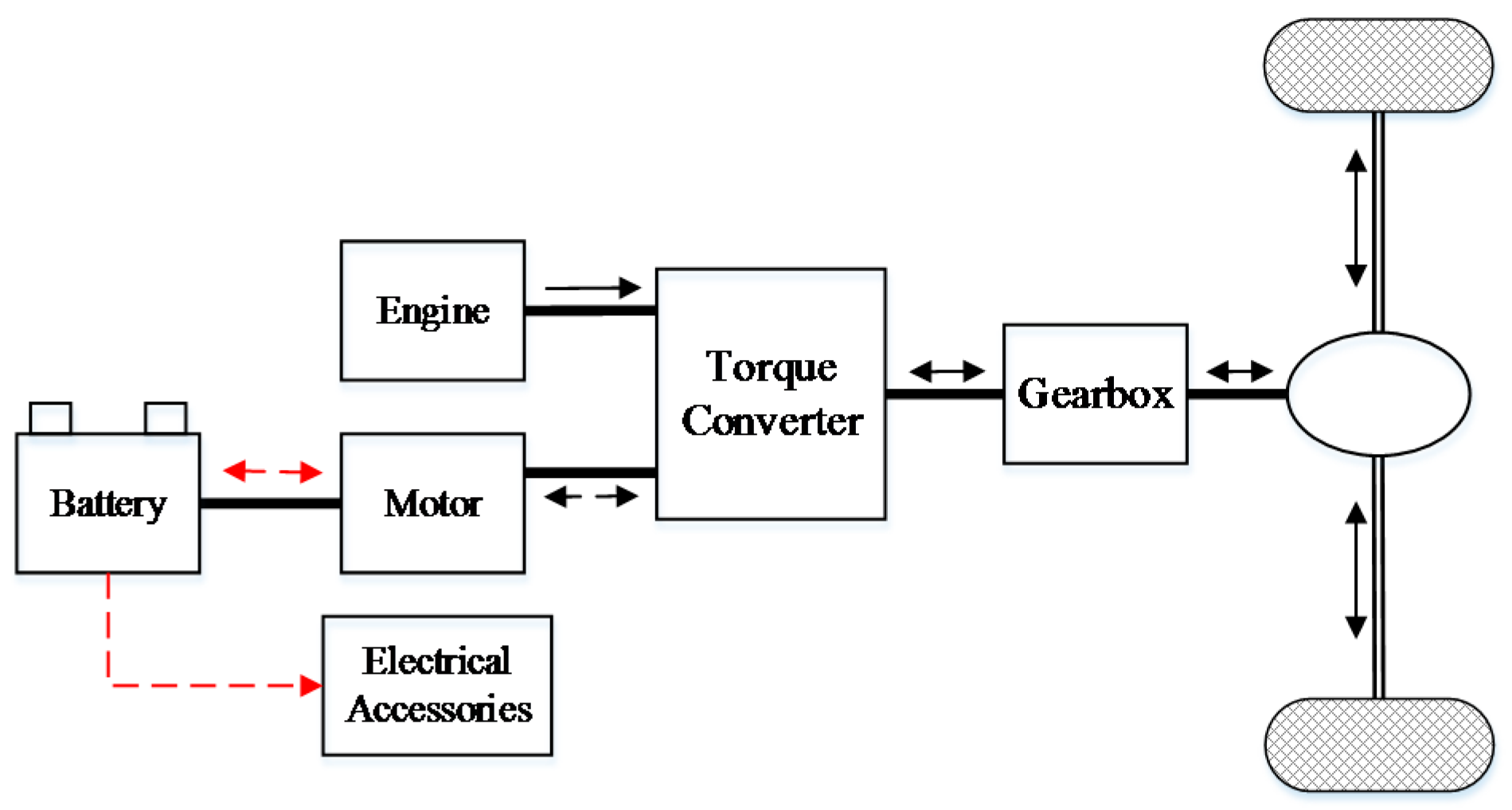
Compared with the optimization-based method, the optimal control parameters of analytic method and rule-based energy management strategy for PHEV can be obtained difficultly. Even the intelligent based method for PHEV has been widely applied, nevertheless, the intelligent based control method is complex and difficult to find the optimal solutions. The optimization-based method can obtain the global optimal solutions, improve the vehicle’s control performance and engine fuel economy. Motivated by these, we plan to compare the performance among different methods. In this paper, there typical methods including the CD/CS method, the DP method, and an intelligent method, i.e., SA combing with the convex optimization are employed to compare the fuel economy for a parallel PHEV. As shown in 
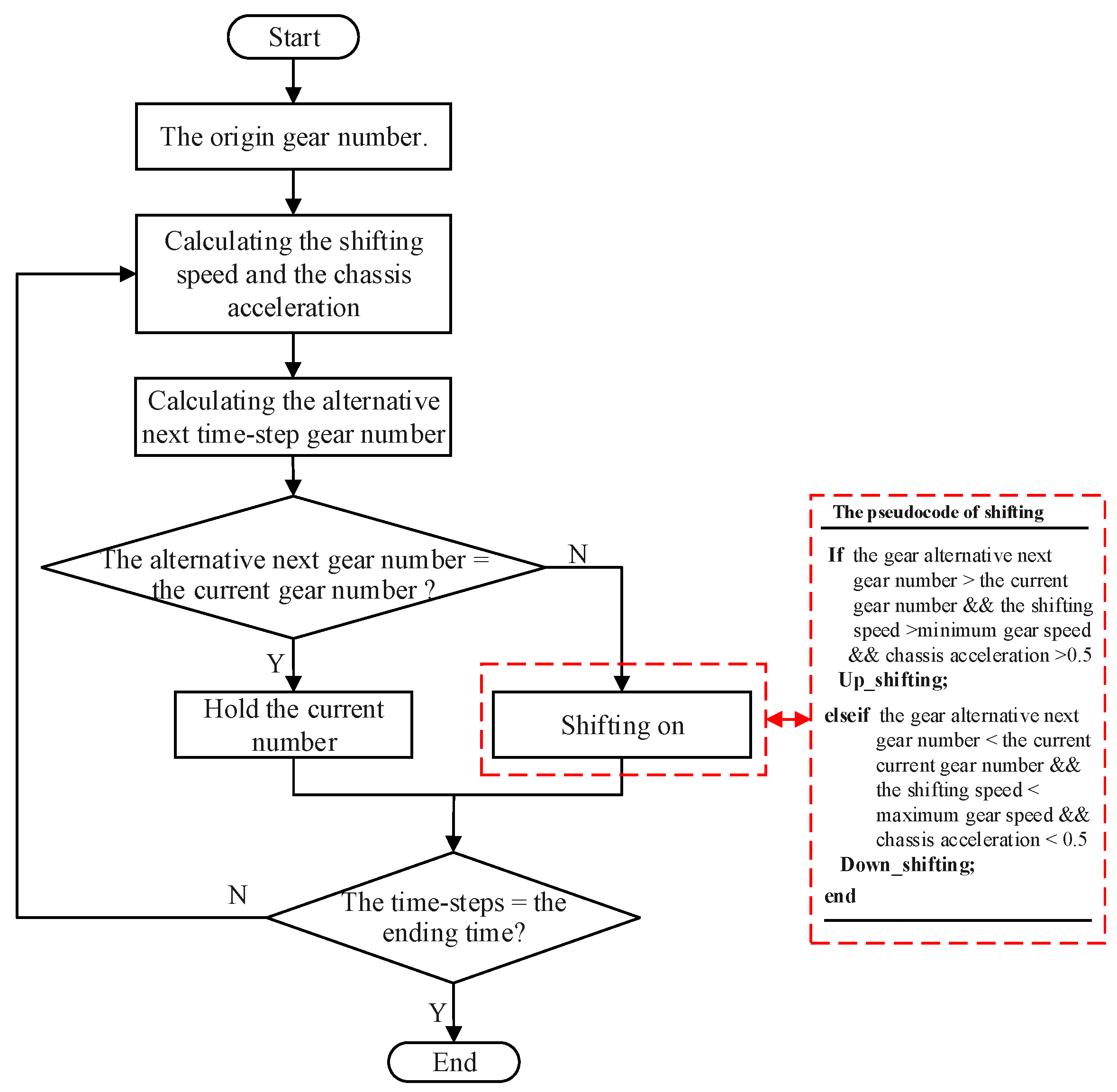
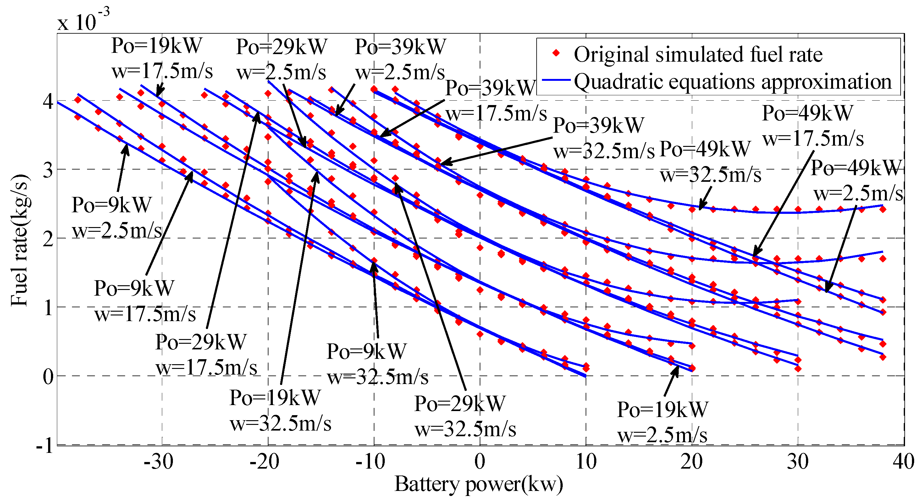
Figure 1, the parallel PHEV can be powered by the engine and motor together. Since the gearbox can select the gear ratio according to the power and speed demand from the driveline, there exist two degrees of freedom in the vehicle, which increases certain complexity to decouple the powertrain dynamics. In order to simplify the problem, an automated gear shift rule strategy is adopted considering the vehicle speed. By this manner, the degrees of freedom changes from two to one and the problem becomes easier to solve. In this paper, the optimization purpose is to minimize the fuel consumption in a certain trip. Based on analysis of the energy flow and the vehicle working modes, the vehicle driveline system is simplified and translated into a series of quadratic equations, which can effectively express the relationship between the engine fuel rate and the battery power at different power demand and velocity. The SA algorithm is implemented to search the optimal engine-on power, in which the optimal sequence of battery power is optimized simultaneously by CP. With considering the referred discussions, the optimal engine-on power is quickly searched by the SA algorithm and then the battery power command is calculated by convex optimization algorithm based on the interior point method. Highway Fuel Economy Driving Schedule (HWFET), New European Driving Cycle (NEDC), and Urban Dynamometer Driving Schedule (UDDS) are selected as test cycles to verify the performance of the proposed algorithm. The CD/CS method and DP are adopted as the benchmark for comparison, and the extended study regarding different initial SOC is also proposed. It is necessary to mention that the proposed algorithm can be easily extended to series connected PHEVs and power-split PHEVs. Thus, it can potentially become a universal control algorithm solution for PHEVs.
The remainder of this paper is structured as follows: Section 2 describes the vehicle model and the model simplification process; Section 3 presents the theory of convex optimization algorithm and the optimization method; Section 4 compares the proposed method with the CD/CS strategy and the DP strategy; and Section 5 concludes the proposed method in the paper.

2. Vehicle Model Analysis and Simplification

As shown in Figure 1, the vehicle driveline system consists of an engine, a battery pack, a clutch, an electric motor, a five-speed gearbox, etc. Compared with the traditional vehicles, two degrees of freedom exist in the PHEV [2]. The main parameters of the PHEV are shown in Table 1. The total vehicle mass is 1720 kg and the maximum engine power and motor power are 65 kW and 70 kW, respectively.

2.1. Engine Model

As shown in Figure 1, the engine fuel consumption of the parallel PHEV as the target function of this paper can be calculated,
F = 0 t t o t a l m f d t
where F is the engine fuel consumption, t t o t a l is the PHEV running time in a certain driving trip, m f is the engine fuel rate. By proper assumption and simplification, m f can be determined,
m f = f ( T e n g , w e n g , e o n )
where T e n g and w e n g are the engine torque and engine speed. e o n is the engine on command. Here we introduce an engine on/off threshold P e n g _ t h r e s h o l d , when the driveline power is more than P e n g _ t h r e s h o l d , the engine will be turned on, or else the engine will be turned off [26],
{ e o n = 1 P 0 P e n g _ t h r e s h o l d e o n = 0 P 0 < P e n g _ t h r e s h o l d
where e o n = 1 represents the engine state is ON, and e o n = 0 means it is OFF. Under a certain drive cycle, the control sequences of the engine state need to be gained and imposed into the control system.

2.2. Electric Machine and Gearbox Unit

A five-speed gearbox is equipped in the parallel PHEV, and the gear ratios equal with 2.563, 1.522, 1.022, 0.727 and 0.52, respectively. In order to simplify the problem, an automated shift rule strategy is adopted considering the vehicle speed and the acceleration. The detailed gear shifting algorithm and the related rules are shown in Figure 2. The gear number up-shifting and down-shifting can be determined based on the shifting speed, chassis acceleration and the current gear number.
Based on the vehicle speed w 0 , and the vehicle acceleration and the driveline power demand P 0 , the power P g b _ i n and speed of gearbox input w g b _ i n k can be correspondingly determined,
P g b _ i n = P 0 / η ( w g b _ i n k , T g b )
w g b _ i n k = w 0 × f f d _ r a t i o r _ w h e e l × f k g b _ r a t i o
where η ( w g b , T g b ) and r _ w h e e l state the efficiency of the gearbox and the radius of the wheel, f f d _ r a t i o is the final driveline ratio equaling with 4.4380, k denotes the numbers of the five-speed gearbox, and f g b _ r a t i o k denotes the gear ratio.
As shown in Figure 1, the torque between the engine and the motor is distributed by a torque converter. Due to the fact that the battery and the motor are connected together, the motor torque T m o t , the motor speed w m o t and P e n g can be calculated,
w m o t = w g b _ i n k × f m o t _ r a t i o
T m o t = f m o t ( P b a t , w m o t )
P e n g = ( P m o t + P g b _ i n ) η c o n v
where η c o n v denotes the efficiency of the torque convertor, f m o t _ r a t i o is the motor drive ratio, P m o t denotes the motor power and equal the product of T m o t and w m o t . In this paper, the accessory power, equaling with 200 W, is considered in P b a t . The constraint conditions boundary of motor torque can be shown as,
T m o t _ min T m o t T m o t _ max
where T m o t _ min and T m o t _ max denote the minimum and maximum values of the motor torque. As shown in Figure 1, w e n g and Teng can be determined,
w e n g = w m o t e o n
T e n g = f e n g ( P e n g , w e n g )
From the above descriptions, we can conclude that m f can be calculated by w 0 , P 0 , e o n and P b a t ,
m f = f ( T e n g , w e n g , e o n ) = f ( w 0 , P 0 , P b a t , e o n )

2.3. Battery Pack Model

A simplified battery model, shown in Figure 3, contains an internal resistor, an open circuit voltage (OCV) source connected in series topology to characterize the battery dynamic and static performance. The simplified model has been widely adopted in developing the energy management strategy without influencing the model precision [2]. The detailed battery parameters are listed in Table 2. It can be found that the capacity is 37 Ah and the nominal voltage is 259.2 V.
The OCV and the internal resistance with respect to the battery SOC are shown in Figure 3. It can be observed that the OCV ranges from 216 V to 288 V. According to the acquired parameters and Figure 4 [40,41], the battery power P b a t can be calculated,
P b a t = U o c v i i 2 R 0
where U o c v and R 0 state the battery OCV and internal resistance, respectively. Now, the battery current i and SOC can be calculated,
i = U o c v U o c v 2 4 R 0 P b a t 2 R 0
S O C ( t + 1 ) = S O C ( t ) i × Δ t C b a t
where S O C 0 denotes the initial battery SOC, Δ t and C b a t are the time interval and the battery capacity, respectively. It is noteworthy that, the above-mentioned specifications regarding battery and gearbox are derived from an existing vehicle model in the simulation software Autonomie.

2.4. Quadratic Static Equation

Based on the above discussion, P b a t can finally determine m f with knowing w 0 and P 0 . In addition, according to (13)–(15), the battery SOC can be calculated based on P b a t . Thus, P b a t can be treated as the control variable and the connection bridge to realize the power split between the engine and the battery. Due to the complex structure and coupling characteristics, the fuel rate can be simplified and can be herein considered as a series of quadratic equations with respect to battery power P b a t , as
m f = { a 2 ( w 0 , P 0 ) P b a t 2 + a 1 ( w 0 , P 0 ) P b a t + a 0 ( w 0 , P 0 ) P 0 P e n g _ t h r e s h o l d 0 P 0 < P e n g _ t h r e s h o l d
where a 2 ( w 0 , P 0 ) , a 1 ( w 0 , P 0 ) and a 0 ( w 0 , P 0 ) are fitting coefficients, which can be determined by w 0 and P 0 .
Figure 5 compares the engine fuel rate calculated by the quadratic equations with that looked up in the engine map, proving the proposed method can accurately describe the fuel rate variation. Hence, the fuel rate can be alternatively described by the quadratic equations efficiently. In terms of knowing the driving cycle, the vehicle speed and driveline power demand can be determined. Thus from (16), we can find that two control variables, i.e., P b a t and e o n , need to be calculated to achieve the energy management. As shown in Figure 6, a 2 ( w 0 , P 0 ) is always more than zero. Then, the proposed method can be translated into a typical convex problem when the engine is on, which can be solved via the interior point method. Additionally, as shown in (16), the engine fuel rate can be also influenced by the engine on/off command. Here, an engine on/off threshold P e n g _ t h r e s h o l d stated in (3) needs to be determined properly to generate the proper engine on/off command and the simulated annealing algorithm is employed to estimate it.
Next step, the interior point method and simulated annealing method are applied together to find the effective solutions for the battery power and engine ON/OFF commands, respectively.

3. Optimization Methods

As presented in (16), the total cost function of this paper can be expressed as,
min F = 0 t t o t a l ( a 2 ( w 0 , P o ) P b a t 2 ( t ) + a 1 ( w 0 , P 0 ) P b a t ( t ) + a 0 ( w 0 , P 0 ) ) e o n ( t ) d t
Based on analysis of the vehicle model, related boundary constraints can be summarized,
{ P e n g _ o n _ min < P e n g _ o n P e n g _ o n _ max P b a t _ min ( t ) P b a t ( t ) P b a t _ max ( t ) 0 Δ S O C 0.7 T m o t _ min T m o t T m o t _ max
where P e n g _ o n _ max is the upper limit of engine-on power threshold, which is equal to the maximum output power of engine, P e n g _ o n _ min is the lower limit of engine-on power threshold, P b a t _ min and P b a t _ max denote the minimum and maximum values of the battery power commands. Δ S O C denotes the range of the battery SOC variation, which is also called the depth of discharge (DOD). In this paper, the ending SOC is set to 0.3, the minimum SOC is 0.2 and thus Δ S O C belongs to [ 0 , 0.7 ] .
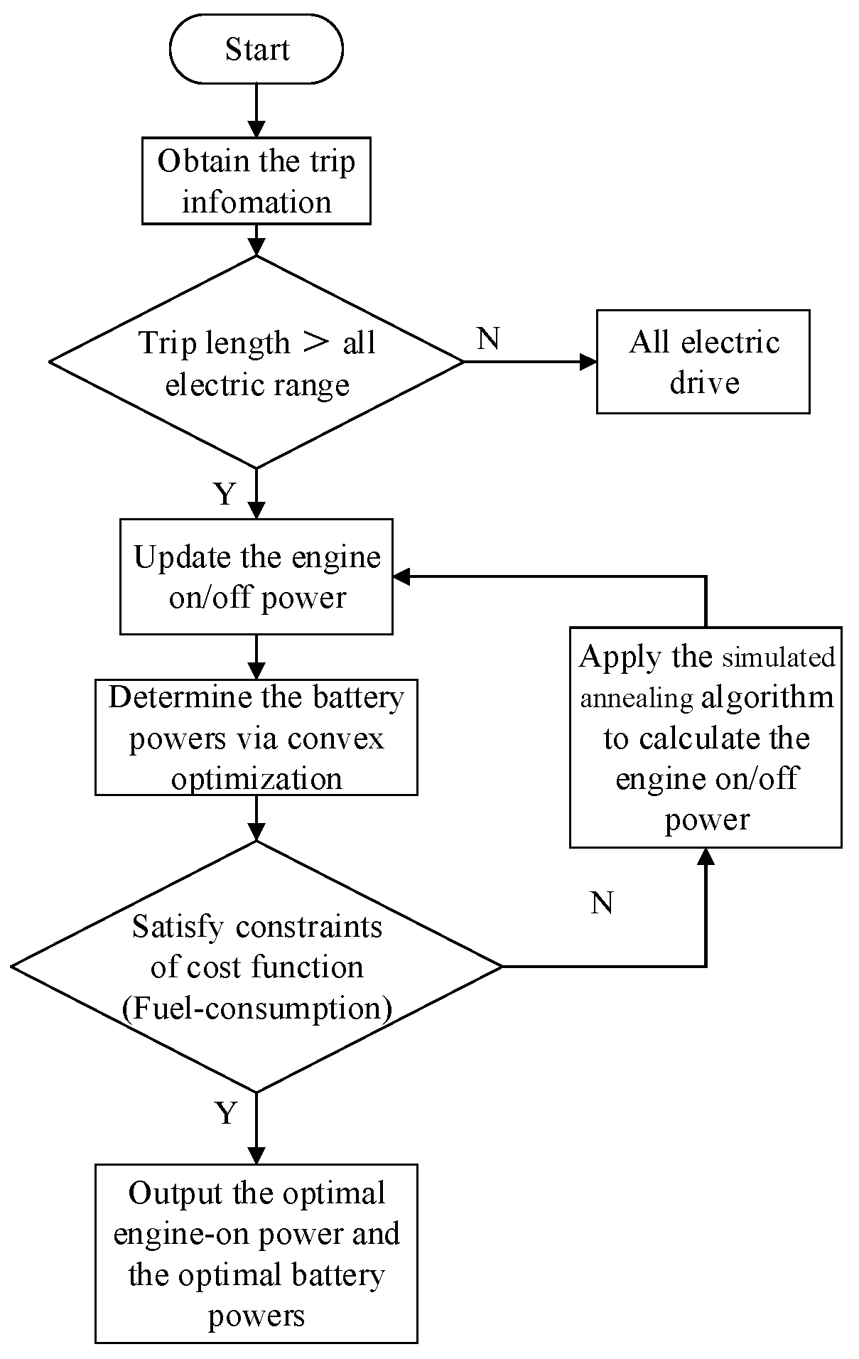
In premise of knowing the driveline power requirements, the engine-on power threshold is solved by the SA algorithm, and the battery power command is calculated by the convex optimization algorithm when the engine is on, as shown in Figure 7. Compared with other optimal algorithms, the SA algorithm is faster and more efficient in solving such global optimization problems with boundary constraints. The calculation process can be described as follows. The first step is to acquire the information of the vehicle including speed, driving range and driveline power demand. Based on the sum of the whole power demand and the maximum battery supplied energy, a decision can be made that if the driving range is less than the AER, the vehicle is under pure EV mode, or else the vehicle is under the HEV mode. If the vehicle works under the HEV mode, an initial engine-on power can be supplied by the SA algorithm. Then, based on the setting constraints, the interior point method will be applied to calculate the battery power thereby realizing the power split between the engine and the battery. Now the fuel consumption based on (17) can be calculated. After that, the SA will be iterated to generate a new engine-on power, and accordingly the battery powers and the total fuel consumption will be updated and compared with the previous calculations. The algorithms will continue to iterate until reaching the termination conditions. Finally, the algorithm outputs the engine-on power and the corresponding battery power commands.
In (18), the lower bound and upper bound on the engine ON/OFF threshold are set to P e n g _ o n _ min and P e n g _ o n _ max . Since the SA algorithm is insensitive to the initial value, the initial engine-on power threshold P e n g _ o n _ i n i t i a l is determined randomly as the initial point between 10 kW and 15 kW and a sufficiently large initial temperature T is randomly selected based on the initial point. After each iteration, an updated state P e n g _ o n _ u p d a t e is generated, and the temperature increment Δ T is calculated comparing with the initial iteration.
Δ T = F ( P e n g _ o n _ u p d a t e * ) F ( P e n g _ o n _ i n i t i a l )
where F denotes the cost function. If Δ T < 0 , P e n g _ o n _ u p d a t e is accepted as the updated current solution. If Δ T > 0 , P e n g _ o n _ i n i t i a l is accepted as the initial current solution with the probability exp ( Δ T / T ) . Then, the battery power is programmed by the convex optimization algorithm combined with P e n g _ o n _ u p d a t e , and the cost consumption function is calculated. The temperature value decreases gradually until reaching the termination condition. Finally, the current solution can be achieved. In this paper, the SA algorithm is performed by MATLAB (2014a, Mathworks, Natick, MA, USA) [22]. In this paper, the number of iterations of the SA algorithm is set to 40, the terminated tolerance is 0.001, and the simulation step is 1 s.
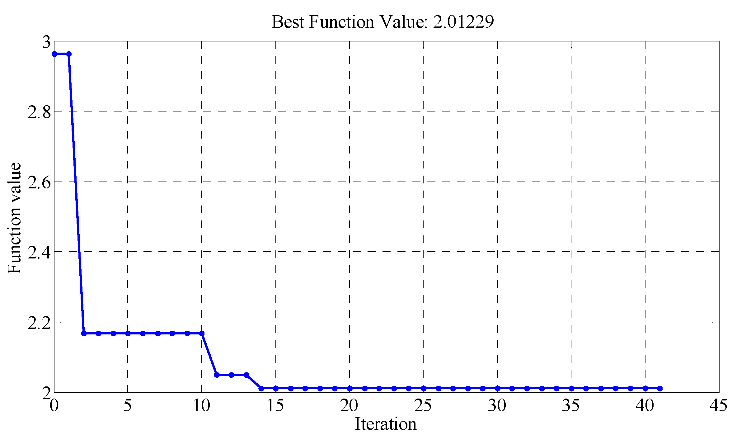
As shown in Figure 8, the calculation process of SA algorithm under nine NEDC cycles is presented. It can be observed that the SA algorithm converges to a minimum value of the cost function after 14th iterations, and stops after 40 generations. The global optimal result can be found after 15 iterations. Next step, simulations will be conducted to verify the fuel savings of the proposed algorithm.

4. Simulation Validation and Results Analysis

In this paper, the whole simulation is carried out under MATLAB and Autonomie. MATLAB is a mathematical calculation software for numerical analysis, matrix operation, algorithm development, etc. Autonomie, developed by the Argonne National Laboratory, is an intelligent vehicle simulation software based on MATLAB and Simulink [22,23].
In order to compare the optimization results, the default CD/CS strategy and the DP algorithm are applied as the benchmark. In the CD mode, the parallel PHEV is driven by the battery when the engine is off. In the CS mode, the engine will be turned on when the driveline power demand is more than the engine-on power threshold and the parallel PHEV is driven by the engine and the battery together. The engine will be turned on when the battery maximum power cannot satisfy the driveline power demand [1,6]. When the engine is on, the engine power should also consider the battery balance control, which means that if the battery SOC is lower than the pre-set value, the battery needs to be charged. The detailed CD/CS strategy can be formulated,
P b a t = { P o S O C 36 % min ( 25317.8 , P o ) 33 % S O C < 36 % min ( 25317.8 ( S O C 0.3 ) / 0.03 , P o ) 30 % S O C < 33 % max ( 30717.3 ( S O C 0.3 ) / 0.03 , P o ) P o < 0 , 27 % S O C < 30 % max ( 30717.3 ( S O C 0.3 ) / 0.03 , P o P e n g _ max ) P o > 0 , 27 % S O C < 30 % max ( 30717.3 , P o ) P o < 0 , S O C < 27 % max ( 30717.3 , P o P e n g _ max ) P o > 0 , S O C < 27 %
where P e n g _ max indexes the maximum power of engine. Based on (20), the battery power is calculated according to the current SOC. In the CD mode, the vehicle is only powered by the battery if the battery SOC is more than 0.36. In the CS mode, the engine is turned on and the battery is charged to hold the SOC near 0.3. In order to verify the control performances more widely, different initial SOC values are considered. We select the initial SOC of 0.9, 0.8 and 0.7 to verify the controlling performances.

4.1. Simulation with Initial SOC of 0.9

We selected two standard drive cycles, i.e., NEDC and HWFET, to validate the performances of the proposed algorithm, DP based method and rule-based method. Figure 9 and Figure 10 show their speed profile and the driveline power, from which we can find that their maximum speeds and maximum driveline power demand are 120 km/h, 96.40 km/h, 38.3 kW and 33.40 kW, respectively.
Based on the proposed algorithm, the optimal engine-on power threshold can be calculated by the SA algorithm. After calculation, the optimal engine-on power thresholds are 15.54 kW, 15.15 kW, and 13.52 kW when seven to nine standard NEDC drive cycles are simulated, and 13.25 kW, 13.05 kW, 12.65 kW and 12.50 kW when six to nine standard HWFET drive cycles are simulated.
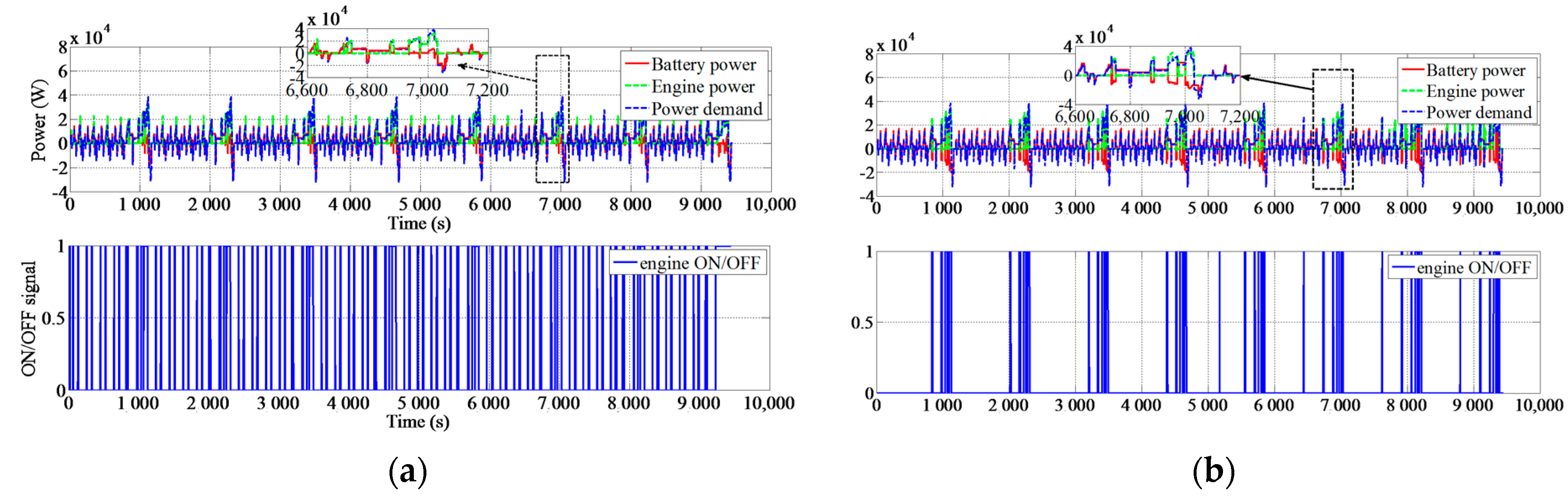
Figure 11 shows the battery power commands, the engine output power, the driveline power demand and the engine on/off commands based on the proposed method when eight NEDC cycles are applied. It is clearly observed that the convex optimization-based method can start the engine more frequently, since it considers the global optimization of the battery and engine efficiency. Therefore, the DP based method is optimal and the convex optimization-based method is sub-optimal. For the existence of electrical accessories and energy loss, the battery power is higher than the driveline power demand when the engine is off. Figure 12 compares the SOC trajectory when different control methods are applied. Obviously, the battery SOC decreases more slowly when the proposed algorithm is applied due to its capability of the global optimization. 
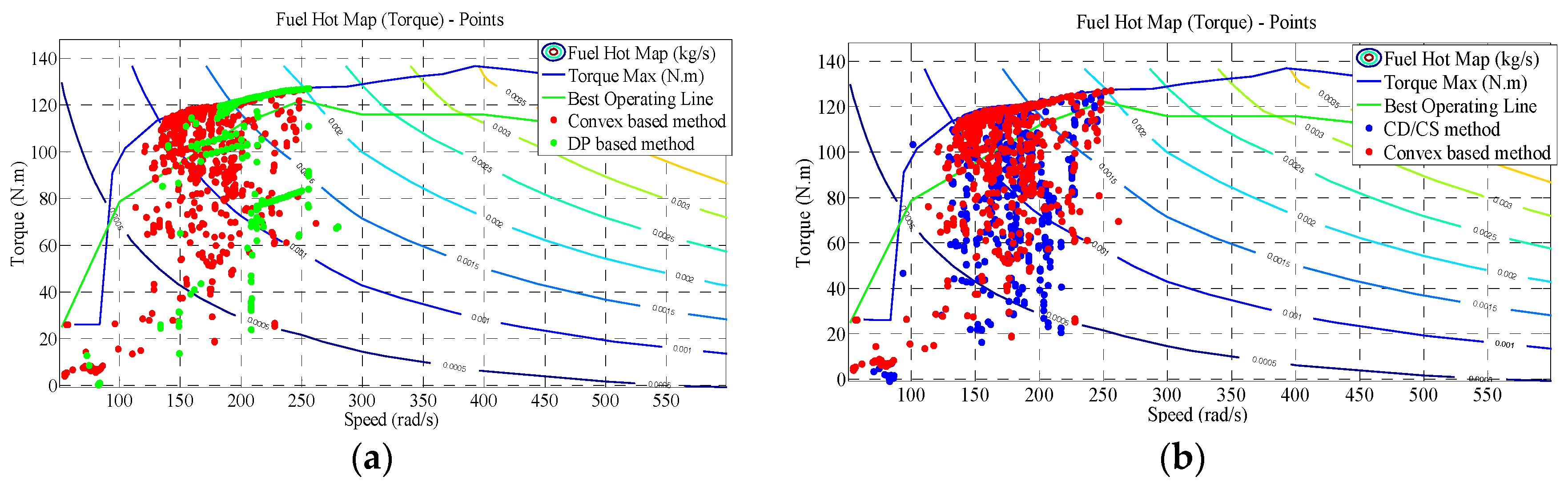
Figure 13 compares the comparison of engine-efficiency points by DP and the proposed method, respectively, from which we can observe that the work efficiency by DP is superior than that by the proposed method and the CD/CS method. In addition, there are also less low efficiency points by the proposed method compared to those by CD/CS method. Actually, the purpose of the proposed algorithm is to increase the opportunity of the engine working in the high efficiency region and thus to improve the fuel economy. As shown in Figure 13, the convex optimization-based method increases the operating chances of engine working near the best operating line.
In order to compare the fuel consumption, a linearly corrected method is applied to ensure the ending SOC with the same value when applying different strategies [2]. Table 3 list the final fuel consumption F , the terminal SOC and the rate of reducing fuel consumption at different cycles. It can be found that the proposed strategy can reduce the fuel consumption by 9.31%, 8.26%, 8.49% when seven to nine NEDC cycles are simulated, and 8.40%, 7.10%, 6.83%, 6.45% when six to nine HWFET cycles are simulated. As shown in Table 3, the fuel savings achieved with the convex optimization-based method are approximate to the DP based method for the HWFET and NEDC driving conditions. In addition, the fuel savings based on the proposed method are currently less than that based on the DP method. As shown in Table 4, the computation time of the DP based method is obviously longer than that of convex optimization-based method, based on a laptop computer of an i7 processor and 4 Gigabyte RAM. Thus, it justifies the effectiveness of reducing the fuel consumption based on the proposed method.

4.2. Simulation with Different Initial SOCs

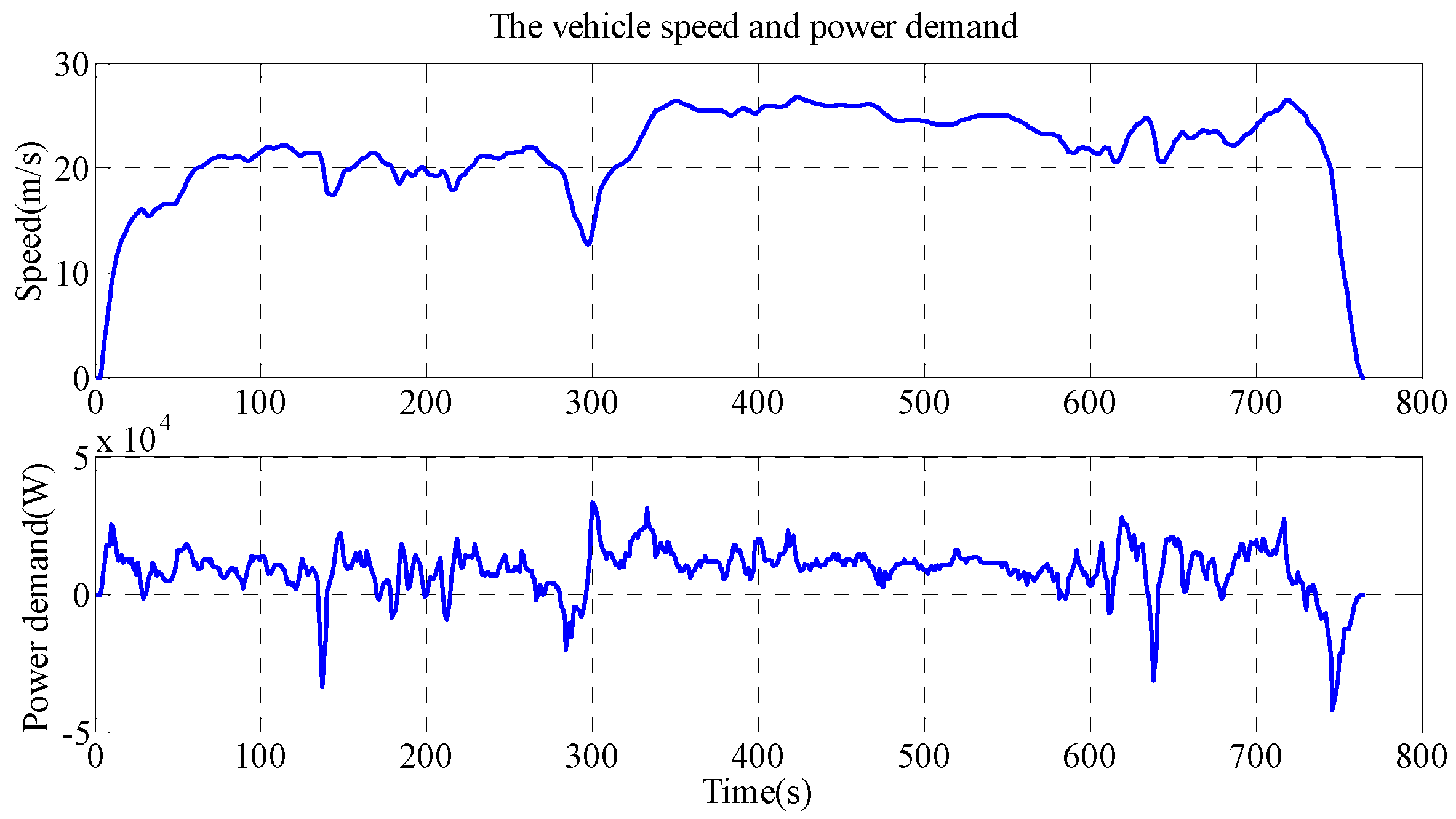
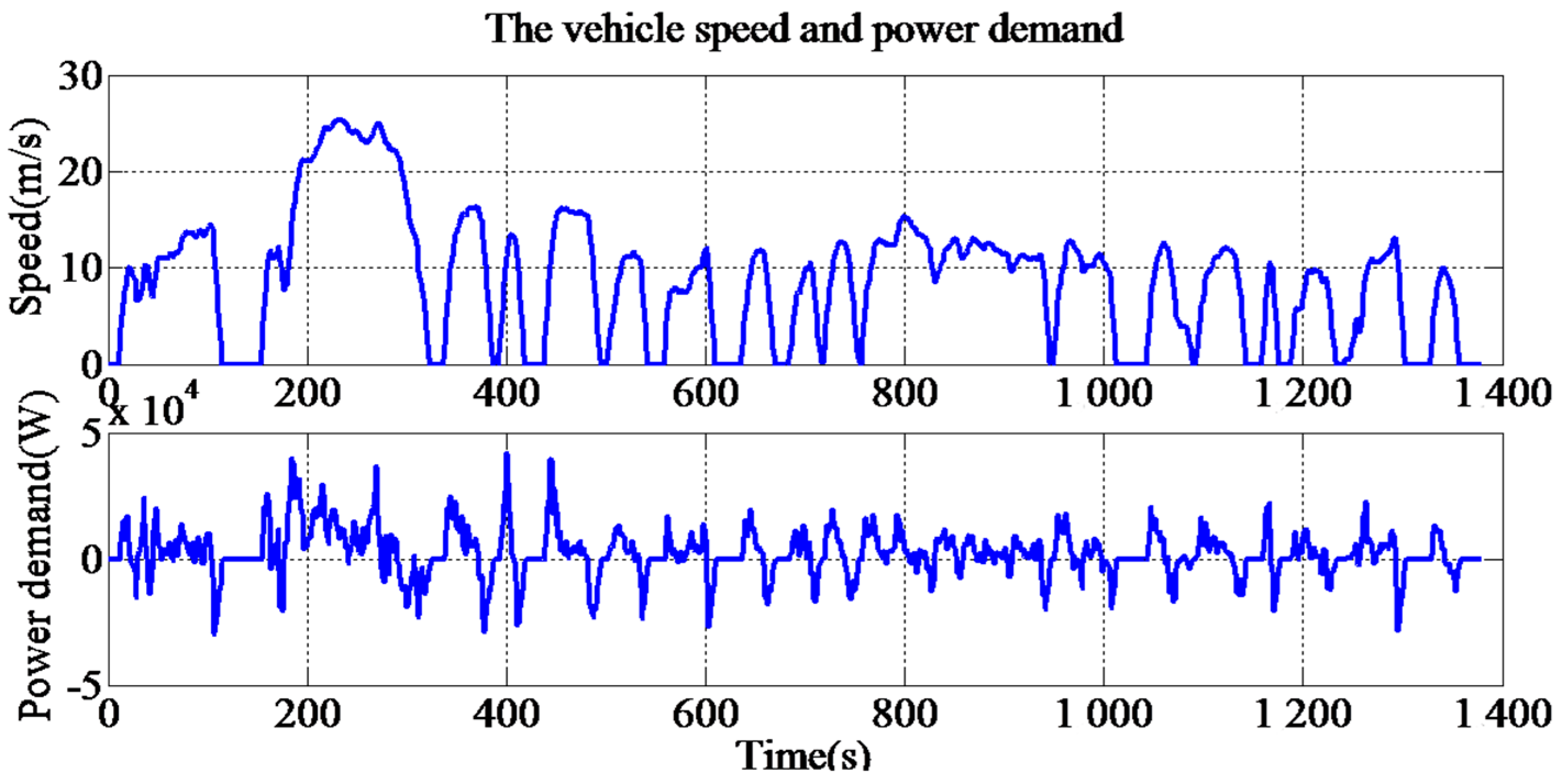
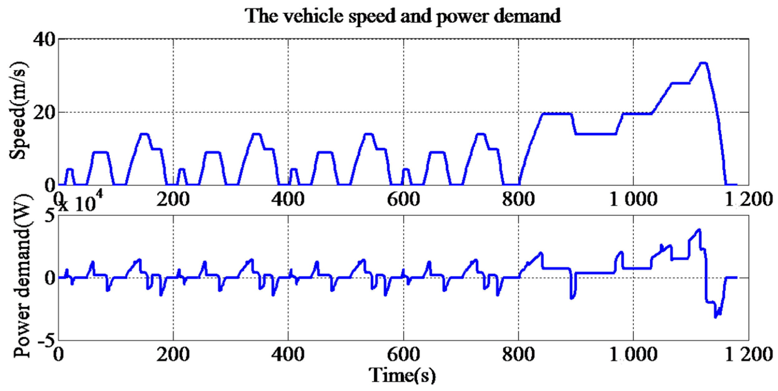
In actual application, it cannot guarantee the battery is always fully charged when the trip begins. Here, the proposed method is extended to consider different initial SOC values. The UDDS cycle, of which the speed and driveline power are shown in Figure 14, is chosen to verify the proposed method with different initial SOC values. The maximum speed and maximum driveline power demand for the UDDS cycle are 91.25 km/h and 41.92 kW, respectively.
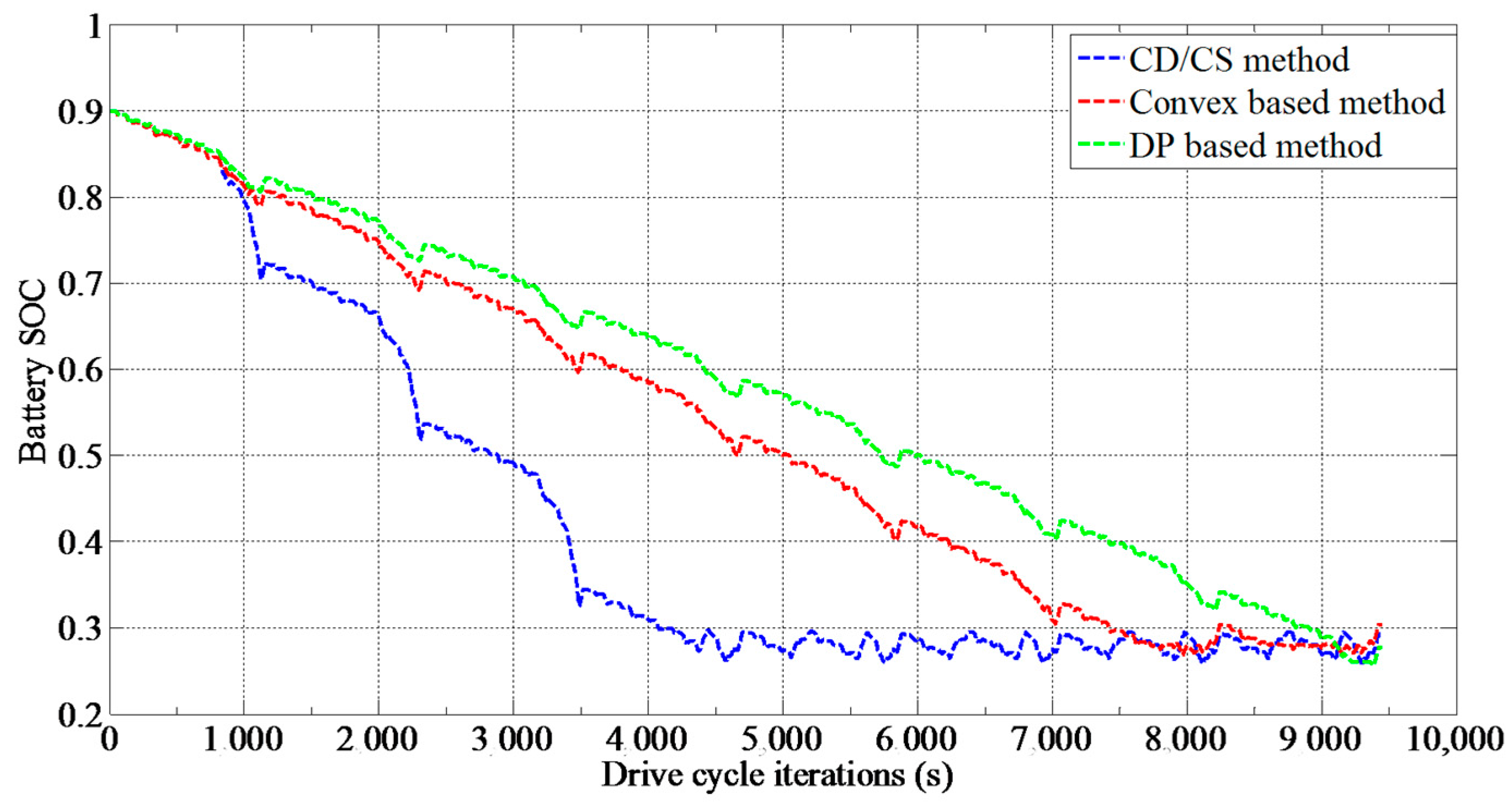
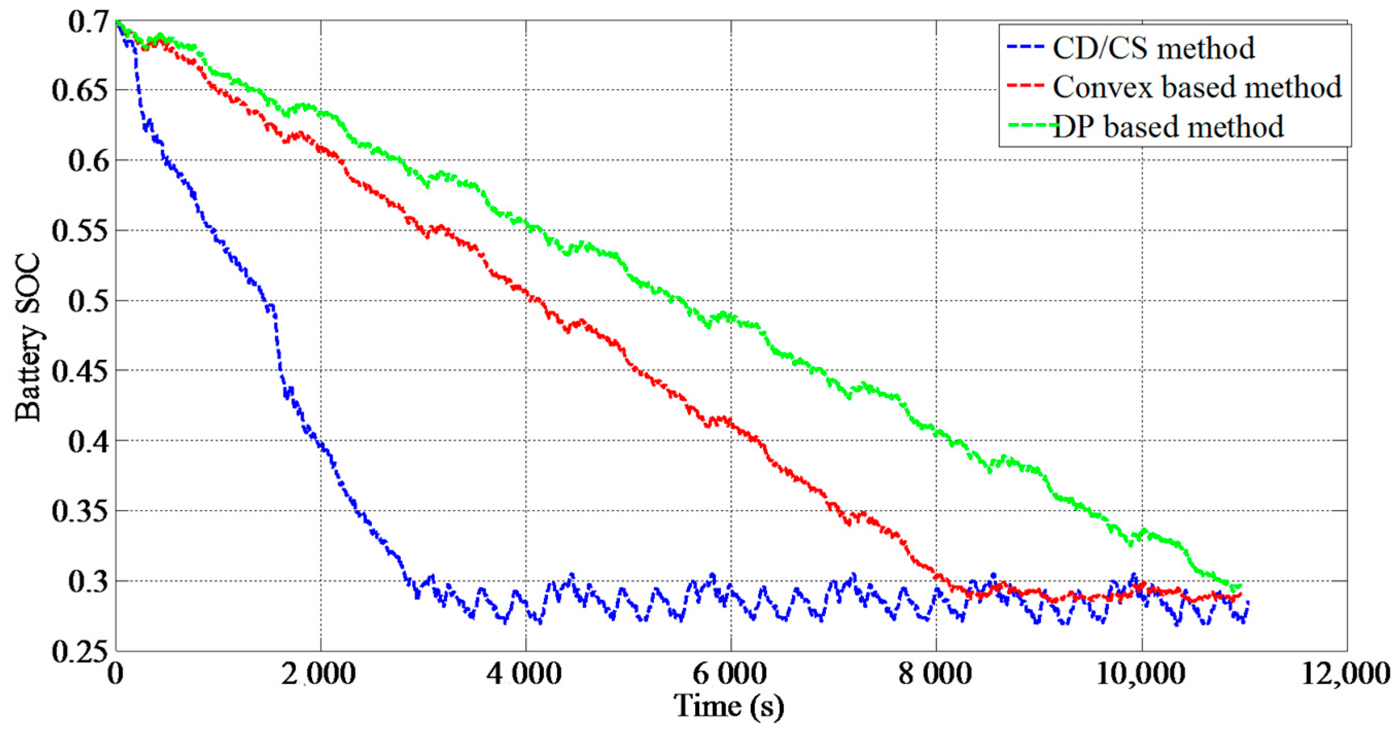
Figure 15 compares the SOC trajectories based on different energy management strategies when the battery initial SOC is 0.7. It shows that the battery is discharged more slowly when the proposed algorithm is applied than that when the CD/CS strategy is applied. Table 5 compares the final results, which show that the proposed method can save fuel consumption by 10.06%, 9.19% when the initial SOC are 0.7 and 0.8 with the SOC correction. Table 6 compares the CPU operation time based on different methods with respect to different initial SOC values. Obviously, the computation time based on convex optimization is obviously less than the DP based method. As shown in Figure 15 and Table 5, the solution based on the convex optimization method can be still acceptable and thus proving its feasibility [39].

5. Conclusions

In order to improve the fuel economy and engine work efficiency, a time efficient energy management strategy is established for the parallel PHEV based on the convex optimization and the SA algorithm. By analyzing the dynamics of the driveline system, the convex quadratic function is built between the engine fuel-rate and the battery power considering requirements of the driveline power and speed. The fuel optimization problem is transformed and solved by the convex optimization algorithm based on the interior point method. In order to extend the proposed method, the convex function is solved at different initial battery SOCs. Compared with the DP based method and the CD/CS method, the proposed method can calculate the engine-on power and the battery power command efficiently, bringing improvement of the engine working efficiency and reduction of the fuel consumption.
Next step work can focus on the hardware-in-loop validation to verify the feasibility of the proposed algorithm and consideration of the battery performance variation under low temperature and degradation.

Acknowledgments

The work is supported by the project of National Science Foundation of China (Grant No. 51567012, 61763021) in part, Research and Development of Test Cycles for Chinese New Energy Vehicles—Data Acquisition in Kunming (Grant No. CF2016-0163) in part, the High-Level Overseas Talents Program of Yunnan Province (Grant No. 10978196) in part, the Innovation Team Program of Kunming University of Science and Technology (Grant No. 14078368) in part, and the Scientific Research Start-up Funding of Kunming University of Science and Technology (Grant No. 14078337) in part. The authors would like to thank them for their support and help. The authors would also like to thank the reviewers for their corrections and helpful suggestions.

Author Contributions

Renxin Xiao and Baoshuai Liu conceived the paper, discussed the convex optimization algorithm and carried out the simulation validation. Zheng Chen built the simplified vehicle model and revised the paper. Jiangwei Shen and Ningyuan Guo analyzed the data and conducted the figures drawing. Wensheng Yan provided some valuable suggestions.

Conflicts of Interest

The authors declare no conflict of interest.

References

  1. Chen, Z.; Mi, C.C. An adaptive online energy management controller for power-split HEV based on dynamic programming and fuzzy logic. In Proceedings of the 2009 IEEE Vehicle Power and Propulsion Conference, 7–11 September 2009; pp. 300–304. [Google Scholar]
  2. Zhang, X.; Mi, C.C. Vehicle Power Management: Modeling, Control and Optimization. Power Syst. 2011, 14, 91–118. [Google Scholar]
  3. Lin, C.C.; Peng, H.; Grizzle, J.W.; Kang, J.M. Power management strategy for a parallel hybrid electric truck. IEEE Trans. Control Syst. Technol. 2003, 11, 839–849. [Google Scholar]
  4. Sorrentino, M.; Rizzo, G.; Arsie, I. Analysis of a rule-based control strategy for on-board energy management of series hybrid vehicles. Control Eng. Pract. 2011, 19, 1433–1441. [Google Scholar] [CrossRef]
  5. Peng, J.; He, H.; Xiong, R. Rule based energy management strategy for a series–parallel plug-in hybrid electric bus optimized by dynamic programming. Appl. Energy 2017, 185 Pt 2, 1633–1643. [Google Scholar] [CrossRef]
  6. Chen, Z.; Mi, C.C.; Xu, J.; Gong, X.; You, C. Energy management for a power-split plug-in hybrid electric vehicle based on dynamic programming and neural networks. IEEE Trans. Veh. Technol. 2014, 63, 1567–1580. [Google Scholar] [CrossRef]
  7. Park, J.; Chen, Z.H.; Murphey, Y.L. Intelligent vehicle power management through neural learning. In Proceedings of the International Joint Conference on Neural Networks, Barcelona, Spain, 18–23 July 2010. [Google Scholar]
  8. Ahmadi, S.; Bathaee, S.M.T. Multi-objective genetic optimization of the fuel cell hybrid vehicle supervisory system: Fuzzy logic and operating mode control strategies. Int. J. Hydrogen Energy 2015, 40, 12512–12521. [Google Scholar] [CrossRef]
  9. Li, S.G.; Sharkh, S.M.; Walsh, F.C.; Zhang, C.N. Energy and battery management of a plug-in series hybrid electric vehicle using fuzzy logic. IEEE Trans. Veh. Technol. 2011, 60, 3571–3585. [Google Scholar] [CrossRef]
  10. Kermani, S.; Delprat, S.; Guerra, T.M.; Trigui, R.; Jeanneret, B. Predictive energy management for hybrid vehicle. Control Eng. Pract. 2012, 20, 408–420. [Google Scholar] [CrossRef]
  11. Zhang, S.; Xiong, R.; Sun, F. Model predictive control for power management in a plug-in hybrid electric vehicle with a hybrid energy storage system. Appl. Energy 2017, 185 Pt 2, 1654–1662. [Google Scholar] [CrossRef]
  12. Xiong, R.; Cao, J.; Yu, Q. Reinforcement learning-based real-time power management for hybrid energy storage system in the plug-in hybrid electric vehicle. Appl. Energy 2018, 211, 538–548. [Google Scholar] [CrossRef]
  13. Chen, Z.; Masrur, M.A.; Murphey, Y.L. In Intelligent vehicle power management using machine learning and fuzzy logic. In Proceedings of the IEEE International Conference on Fuzzy Systems, Hong Kong, China, 1–6 June 2008; pp. 2351–2358. [Google Scholar]
  14. Zhang, M.Y.; Yang, Y.; Mi, C.C. Analytical approach for the power management of blended-mode plug-in hybrid electric vehicles. IEEE Trans. Veh. Technol. 2012, 61, 1554–1566. [Google Scholar] [CrossRef]
  15. Zhang, X.; Mi, C. Analytical approach for the power management of blended mode phev. In Vehicle Power Management: Modeling, Control and Optimization; Springer: London, UK, 2011; pp. 107–139. [Google Scholar]
  16. Ansarey, M.; Panahi, M.S.; Ziarati, H.; Mahjoob, M. Optimal energy management in a dual-storage fuel-cell hybrid vehicle using multi-dimensional dynamic programming. J. Power Sources 2014, 250, 359–371. [Google Scholar] [CrossRef]
  17. Wang, X.; He, H.; Sun, F.; Zhang, J. Application study on the dynamic programming algorithm for energy management of plug-in hybrid electric vehicles. Energies 2015, 8, 3225–3244. [Google Scholar] [CrossRef]
  18. Patil, R.M.; Filipi, Z.; Fathy, H.K. Comparison of supervisory control strategies for series plug-in hybrid electric vehicle powertrains through dynamic programming. IEEE Trans. Control Syst. Technol. 2014, 22, 502–509. [Google Scholar] [CrossRef]
  19. Wang, X.; Liang, Q. Energy management strategy for plug-in hybrid electric vehicles via bidirectional vehicle-to-grid. IEEE Syst. J. 2017, 11, 1789–1798. [Google Scholar] [CrossRef]
  20. Li, L.; Yan, B.; Yang, C.; Zhang, Y.; Chen, Z.; Jiang, G. Application-oriented stochastic energy management for plug-in hybrid electric bus with amt. IEEE Trans. Veh. Technol. 2016, 65, 4459–4470. [Google Scholar] [CrossRef]
  21. Zhang, S.; Xiong, R.; Zhang, C. Pontryagin’s minimum principle-based power management of a dual-motor-driven electric bus. Appl. Energy 2015, 159, 370–380. [Google Scholar] [CrossRef]
  22. Chen, Z.; Xia, B.; You, C.; Mi, C.C. A novel energy management method for series plug-in hybrid electric vehicles. Appl. Energy 2015, 145, 172–179. [Google Scholar] [CrossRef]
  23. Chen, Z.; Mi, C.C.; Xiong, R.; Xu, J.; You, C.W. Energy management of a power-split plug-in hybrid electric vehicle based on genetic algorithm and quadratic programming. J. Power Sources 2014, 248, 416–426. [Google Scholar] [CrossRef]
  24. Hadj-Said, S.; Colin, G.; Ketfi-Cherif, A.; Chamaillard, Y. Convex optimization for energy management of parallel hybrid electric vehicles. IFAC Papersonline 2016, 49, 271–276. [Google Scholar] [CrossRef]
  25. Hu, X.S.; Murgovski, N.; Johannesson, L.M.; Egardt, B. Optimal dimensioning and power management of a fuel cell/battery hybrid bus via convex programming. IEEE-ASME Trans. Mechatron. 2015, 20, 457–468. [Google Scholar] [CrossRef]
  26. Elbert, P.; Nusch, T.; Ritter, A.; Murgovski, N.; Guzzella, L. Engine on/off control for the energy management of a serial hybrid electric bus via convex optimization. IEEE Trans. Veh. Technol. 2014, 63, 3549–3559. [Google Scholar] [CrossRef]
  27. Hu, X.; Moura, S.J.; Murgovski, N.; Egardt, B.; Cao, D. Integrated optimization of battery sizing, charging, and power management in plug-in hybrid electric vehicles. IEEE Trans. Control Syst. Technol. 2016, 24, 1036–1043. [Google Scholar] [CrossRef]
  28. Bandeira, J.; Almeida, T.G.; Khattak, A.J.; Rouphail, N.M.; Coelho, M.C. Generating emissions information for route selection: Experimental monitoring and routes characterization. J. Intell. Transp. Syst. 2013, 17, 3–17. [Google Scholar] [CrossRef]
  29. Zhang, Y.; Liu, H.P.; Guo, Q. Varying-domain optimal management strategy for parallel hybrid electric vehicles. IEEE Trans. Veh. Technol. 2014, 63, 603–616. [Google Scholar] [CrossRef]
  30. Tie, S.F.; Tan, C.W. A review of energy sources and energy management system in electric vehicles. Renew. Sustain. Energy Rev. 2013, 20, 82–102. [Google Scholar] [CrossRef]
  31. Zhang, B.Z.; Mi, C.C.; Zhang, M.Y. Charge-depleting control strategies and fuel optimization of blended-mode plug-in hybrid electric vehicles. IEEE Trans. Veh. Technol. 2011, 60, 1516–1525. [Google Scholar] [CrossRef]
  32. Kelouwani, S.; Henao, N.; Agbossou, K.; Dube, Y.; Boulon, L. Two-layer energy-management architecture for a fuel cell hev using road trip information. IEEE Trans. Veh. Technol. 2012, 61, 3851–3864. [Google Scholar] [CrossRef]
  33. Onori, S.; Tribioli, L. Adaptive pontryagin’s minimum principle supervisory controller design for the plug-in hybrid gm chevrolet volt. Appl. Energy 2015, 147, 224–234. [Google Scholar] [CrossRef]
  34. Hu, X.; Martinez, C.M.; Yang, Y. Charging, power management, and battery degradation mitigation in plug-in hybrid electric vehicles: A unified cost-optimal approach. Mech. Syst. Signal Process. 2017, 87, 4–16. [Google Scholar] [CrossRef]
  35. Johannesson, L.; Murgovski, N.; Jonasson, E.; Hellgren, J.; Egardt, B. Predictive energy management of hybrid long-haul trucks. Control Eng. Pract. 2015, 41, 83–97. [Google Scholar] [CrossRef]
  36. Murgovski, N.; Johannesson, L.; Sjöberg, J.; Egardt, B. Component sizing of a plug-in hybrid electric powertrain via convex optimization. Mechatronics 2012, 22, 106–120. [Google Scholar] [CrossRef]
  37. Nüesch, T.; Elbert, P.; Flankl, M.; Onder, C.; Guzzella, L. Convex optimization for the energy management of hybrid electric vehicles considering engine start and gearshift costs. Energies 2014, 7, 834–856. [Google Scholar] [CrossRef]
  38. Chen, Z.; Mi, C.C.; Xia, B.; You, C. Energy management of power-split plug-in hybrid electric vehicles based on simulated annealing and pontryagin’s minimum principle. J. Power Sources 2014, 272, 160–168. [Google Scholar] [CrossRef]
  39. Wang, Z.; Huang, B.; Xu, Y.; Li, W. In Optimization of series hybrid electric vehicle operational parameters by simulated annealing algorithm. In Proceedings of the IEEE International Conference on Control and Automation, Athens, Greece, 30 May 2007–1 June 2007; pp. 1536–1541. [Google Scholar]
  40. Van Mierlo, J.; Van den Bossche, P.; Maggetto, G. Models of energy sources for ev and hev: Fuel cells, batteries, ultracapacitors, flywheels and engine-generators. J. Power Sources 2004, 128, 76–89. [Google Scholar] [CrossRef]
  41. He, H.; Xiong, R.; Guo, H.; Li, S. Comparison study on the battery models used for the energy management of batteries in electric vehicles. Energy Convers. Manag. 2012, 64, 113–121. [Google Scholar] [CrossRef]
Figure 1. Powertrain structure of a parallel plug-in hybrid electric vehicle.
Applsci 08 00218 g001
Figure 2. Gear shifting strategy.
Applsci 08 00218 g002
Figure 3. The battery internal resistance and the open circuit voltage (OCV) curve with respect to state of charge (SOC).
Applsci 08 00218 g003
Figure 4. Simplified model of the battery pack.
Applsci 08 00218 g004
Figure 5. Fuel-rate validation and approximation.
Applsci 08 00218 g005
Figure 6. a 2 ( w 0 , P 0 ) .
Applsci 08 00218 g006
Figure 7. The whole optimization calculation process. SA: simulated annealing.
Applsci 08 00218 g007
Figure 8. The calculation process of simulated annealing (SA) algorithm method.
Applsci 08 00218 g008
Figure 9. Speed and driveline power demand for the New European Driving Cycle (NEDC).
Applsci 08 00218 g009
Figure 10. Speed and driveline power demand for the Highway Fuel Economy Driving Schedule (HWFET).
Applsci 08 00218 g010
Figure 11. (a) The result based on dynamic programming (DP) when eight NEDC cycles are simulated; (b) The result based on convex optimization and SA when eight NEDC cycles are simulated.
Applsci 08 00218 g011
Figure 12. Battery SOC comparison.
Applsci 08 00218 g012
Figure 13. (a) Engine efficiency comparison between the convex programming-based strategy and the strategy based on DP; (b) Engine efficiency comparison between charging depleting–charging sustaining (CD/CS) strategy and the convex programming-based method.
Applsci 08 00218 g013
Figure 14. Speed and driveline power demand for Urban Dynamometer Driving Schedule (UDDS) drive cycle.
Applsci 08 00218 g014
Figure 15. Battery SOC comparisons when the initial SOC is 0.7.
Applsci 08 00218 g015
Table 1. Vehicle parameters.
TypeParallel PHEV Value
Vehicle mass1720 kg
Drive typeFront wheel drive
EngineMaximum power 65 kW
Maximum speed 6000 rpm
MotorRated power 30 kW
Peak power 70 kW
Table 2. Battery parameters. SOC: state of charge.
TypeParameter
Battery typeLithium-ion battery
Parallel number1
Serial number72
Minimum SOC 0.2
Maximum SOC1
Initial SOC0.9
Termination SOC0.3
Capacity37 Ah
Nominal voltage259.2 V
Table 3. Results comparison with standard initial SOC. CD/CS: charging depleting–charging sustaining; DP: dynamic programming; HWFET: Highway Fuel Economy Driving Schedule; NEDC: New European Driving Cycle.
Drive CycleCD/CS AlgorithmDP AlgorithmConvex Algorithm
F (kg)Ending SOCF (kg)Ending SOCSavings (%)F (kg)Ending SOCSavings (%)
9 HWFET3.70040.27673.49800.30316.823.50300.29866.45
8 HWFET3.16660.27672.98170.30277.392.99340.29956.83
7 HWFET2.63280.27672.47190.30227.942.47680.29307.10
6 HWFET2.09900.27671.96550.30178.621.96560.29948.40
9 NEDC1.98030.29231.84490.31158.671.84860.31168.49
8 NEDC1.63250.29231.46870.27728.291.51870.30348.26
7 NEDC1.28470.29231.20590.31039.911.19100.30609.31
Table 4. Computation time comparison with standard initial SOC.
Drive CycleCPU Time (s)
DP AlgorithmConvex Algorithm
9 HWFET170.53.1
8 HWFET151.92.8
7 HWFET133.12.5
6 HWFET114.52.5
9 NEDC227.97.0
8 NEDC189.95.5
7 NEDC176.74.2
Table 5. Results comparison with different initial SOC.
Initial SOCCD/CS AlgorithmDP AlgorithmConvex Algorithm
F (kg)Ending SOCF (kg)Ending SOCSavings (%)F (kg)Ending SOCSavings (%)
0.72.18710.28591.97290.296910.751.97580.290510.06
0.81.99880.28591.78420.298611.931.81080.28369.19
Table 6. Results comparison with different initial SOC.
Initial SOCDrive CycleCPU-Time (s)
DP AlgorithmConvex Algorithm Optimization
0.88 UDDS269.62.7
0.78 UDDS270.14.9

