1. Introduction
Nanomaterials have revolutionized many industrial and household appliances. Their use is gaining considerable popularity, and the fields of science associated with them enjoy a similar repute. Nanotechnology and its consequent products have many useful applications in various fields of science and engineering, from enhancing thermal properties of traditional fluids to construction of an effective drug delivery system. Other examples include electronics, life sciences, chemical synthesis, fuel cells, medical sciences, microsystems including mechanical and electrical components, etc. Nanofluids are formed by the addition of nano-sized particles in base fluids, which traditionally have poor thermal properties. These additives work as boosters and the resulting substance, i.e., nanofluid, bears some remarkable thermal properties [
1,
2,
3,
4,
5]. Several mathematical models describe the properties of nanofluids. Choi [
6] was the pioneer who witnessed and announced the existence of the tiny particles and their effectiveness. He examined through several experiments that the addition of nanometer sized particles of various nature exceptionally enhance the thermal properties of base fluids. Later, Choi et al. [
7] presented a mathematical model which provides some new insights related to the field of nanotechnology. Following in his footsteps, many researchers carried out several research activities. Subsequently, several models have been proposed for different physical and industrial problems. One of these models is presented by Buongiorno [
8]. His model considers both thermophoretic and Brownian motion effects. Hamilton and Crosser [
9] formulated another model which describes the effects of shapes of nanoparticles. Some other famous models include Maxwell’s [
10] and Xue’s [
11] models. Khan and Pop utilized Buongiorno’s concept to model a boundary layer flow over a stretching sheet [
12]. There has been several efforts to use these models in different situations and geometries. Some of the most recent can be found in [
13,
14,
15,
16,
17,
18,
19,
20].
In 1991, Iijima [
21] introduced a cylindrical member of fullerenes family named as carbon nanotubes (CNTs). They possess unique electronic, mechanical, chemical, optical, catalytic, adsorption, and transport properties, which make them very valuable for a wide range of applications [
22,
23]. They are mainly categorized in two modules, one Single-walled carbon nanotubes (SWCNTs) and the other multi-walled carbon nanotubes (MWCNTs). The term single refers to a single layer or wall that holds all the particles together, whereas the term multi-walled refers to a bunch of nested tubes whose diameter is continuously growing. It has been observed that the enhancement of thermal properties of base fluid using CNTs as nanoparticles is remarkable. Murshed et al. [
24] showed that CNTs produce six times better thermal conductivity, at room temperature, as compared to other substances. The role of CNTs in enhancement of thermal properties of the base fluid has been highlighted by many scientists, in different scenarios and geometries [
25,
26,
27,
28].
During the last few years, researchers are showing a keen interest in understanding the flows of boundary layer nature over a dilating or a squeezing curved sheet. These types of flows bear commendable uses in different engineering and industrial processes such as production of papers, polymer sheet, manufacturing of rubber and plastic sheets, glass fibers, wire coating, food manufacturing, etc. In 1961, Sakiadis [
29] was the first to come up with the idea of boundary layer flows. He presented the flow over a stretching surface. Crane [
30] extended his idea for both linear and exponentially stretching sheets. He derived a closed form solution for the viscid flow caused by the stretching of a sheet. McLeod and Rajagopal [
31] examined the uniqueness of the exact solution [
30]. Since the pioneering work, flow problems related to a stretching surface under different situations have been analyzed by many scientists. Some of them can be found in References [
32,
33,
34,
35,
36,
37].
The energy crisis has become a major cause of concern in modern world. To meet a growing demand for energy, a new wave of innovative models is required that can replace the traditional ones. The resources for renewable energy, including solar and wind power, are now well placed to contribute to energy requirements in both mature and developing economies. Thermal radiation gains a great significance for such processes where the systems are running at very high temperatures, e.g., heating and cooling chambers, solar power technology, electrical power generation, thermal energy storage, nuclear power plants and many other industrial areas. Due to these important applications, many authors have contributed in studying the radiative flows of different fluids in various geometrical configurations [
38,
39].
Besides conduction and radiation, another means of heat transfer, i.e., convection, also plays a pivotal role in many real-life problems. Heat transfer via convection has been a core subject of many scientific investigations. Its role is very prominent in a wide range of energy-related applications such as automobile radiators, lubricants and coolants in various mechanical processes, etc. An asymptotic solution, by involving homotopy analysis method, to the stagnation point nanofluid flow (with a heat generation source) over a dilating permeable sheet was explained by Malvandi et al. [
40]. Tsai et al. [
41] focused on the influence of flow and heat transfer coupled with non-uniform heat source over an unsteady stretching surface. Pal [
42] examined the radiative flow over an unsteady expanding surface with variable heat generating/consuming mechanism.
Previously, studies on the flows over flat surfaces were carried out using Cartesian coordinate systems. Recently, Sajid et al. [
43] came up with an idea of curved surface and modeled the flow phenomena using a curvilinear coordinate system. Abbas with his coworkers [
44] followed their approach and applied it to present a thermal analysis of the flow over a bent sheet. In 2016, Abbas et al. [
45] studied the hydromagnetic and radiative slip flow of a nanofluid over a curved stretching surface along with heat generation. Most recently, a considerable interest has been shown by many authors in studying the flow over curved surfaces [
46,
47,
48]. These recent efforts by renowned scholars have motivated us to carry out this work. We have examined the heat transfer in a radiative boundary layer flow, heat generation, of a carbon nanotube (CNT)-based nanofluid over a curved stretching sheet. Shooting method followed by Runge–Kutta–Fehlberg scheme is employed to obtain a numerical solution of the problem. Consequently, a comprehensive graphical description (highlighting the effects of various parameters on the velocity, pressure and temperature profiles) of the flow behavior is presented.
2. Formulation of the Problem
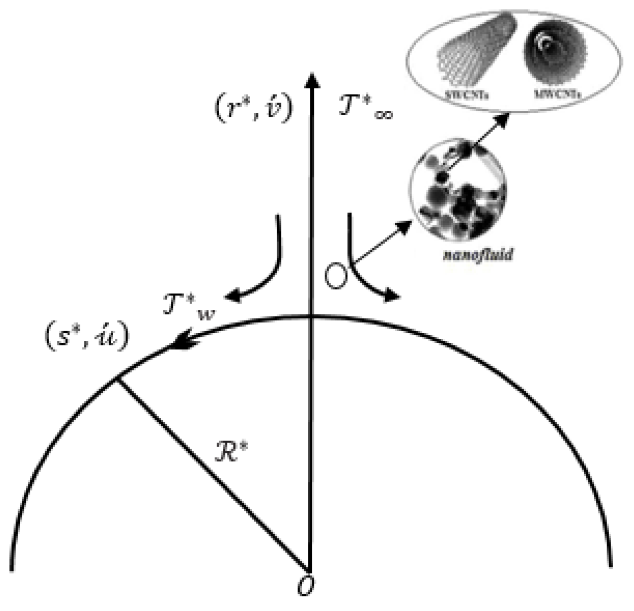
We consider a laminar flow of an incompressible nanofluid over a curved stretching sheet at
(see
Figure 1). The flow is steady and two dimensional. The nanofluid under consideration is composed of CNT nanoparticles added to a base fluid (water). Since we are dealing with a curved sheet that is being stretched in opposite direction by two forces of same magnitude, we use curvilinear coordinates
. The linear velocity by which the sheet is being stretched is taken to be
, where
is a positive constant. The temperature of the sheet is represented by
(
where
is a constant). The free stream temperature is denoted by
and it is assumed that
.
In context of the aforementioned coordinate scheme and the assumptions along with the boundary layer approximation, the equations representing the conservative balance for mass, momentum and energy are given as follows:
where
. In the above set of equations, the velocities along
and
are denoted by the symbols
and
, respectively. Moreover,
represents the dimensional pressure,
describes the radiative heat flux and
is the base fluid temperature. The term
arises due to heat generation and it represents the volumetric rate of heat generation through a source. Furthermore,
denotes volumetric heat capacity of the nanofluid and
is its dynamic viscosity. Effective density and the thermal conductivity of the nanofluid are respectively symbolized by
and
[
11,
27,
49]. Mathematically:
where the base fluid viscosity is represented by
,
denotes the nanoparticle volume fraction and
is the thermal diffusivity. Moreover,
and
represent the thermal conductivities and densities of base fluid and CNT, respectively. The following table highlights the thermo-physical properties of pure water (base fluid) and CNTs.
The associated boundary conditions are imposed as follows:
The radiative heat flux is defined by the means of Rosseland approximation [
50] as:
where Stefan–Boltzmann constant and Rosseland mean absorption coefficient, are
and
, respectively. The small changes in temperature diffusion are assumed in such a way that we may expand the Taylor series expansion of
about
and ignore the terms of higher order. Consequently, we get
By substituting Equations Equations (9) and (10) into Equation (4), we get
Now by assuming
as a radiation parameter, following Magyari and Pantokratoras [
51], Equation (11) becomes
where Prandtl number is given as
.
The dimensionless transformation variables, for the simplification of the flow equations, are defined as:
The substitution of above equation implies an automatic satisfaction of the continuity Equation (1), while Equations (2), (3) and (12) are given as:
where dimensionless radius of curvature and heat generation parameter are
and
, respectively. The classical energy equation can be recovered from Equation (6) by ignoring the radiative
and heat generation
effects. Moreover, it is noteworthy that by taking
and in the absence of pressure gradient, Equation (15) gets converted to the classical problem of flat stretching sheet as discussed by Crane [
30],
The implementation of Equation (13) reduces the boundary conditions to a dimensionless form given as:
We can eliminate
from Equations (14) and (15). Consequently,
where
After obtaining
,
can be easily determined from Equation (15) as:
The skin-friction coefficient
and the local Nusselt number
in
-direction are given by:
where
represents the wall shear stress and
symbolizes the wall heat flux in
-direction. Their mathematical expression are as follows:
Using Equations (13), (21) and (22) becomes:
where the local Reynolds number is symbolized by
.
4. Results and Discussions
The size and shape of nanocomposites matter greatly for enhaning the thermal properties of the base fluid. Carbon nanotubes are long nanotube wires with distinctive size and shape and also possess significant physical properties. They are supposed to be much better than steel and Kevlar due to the material’s exceptional tensile strength and stiffness. Thus, the flow and heat transfer characteristics of single- and multi-walled carbon nanotubes over a curved stretching sheet have been investigated. The mass flow rate is assumed to be 0.02
. The core objective of this section is to graphically demonstrate the influence of various parameters like dimensionless radius of curvature
, nanoparticle volume fraction Φ (ranging from
), heat generation parameter
and radiation parameter Rd on the velocity, temperature and pressure profiles.
Table 1 displays the thermo-physical properties of the base fluid and the nanoparticles. Since water has been utilized as a base fluid, therefore, a fixed value for Prandtl number (
) has been used.
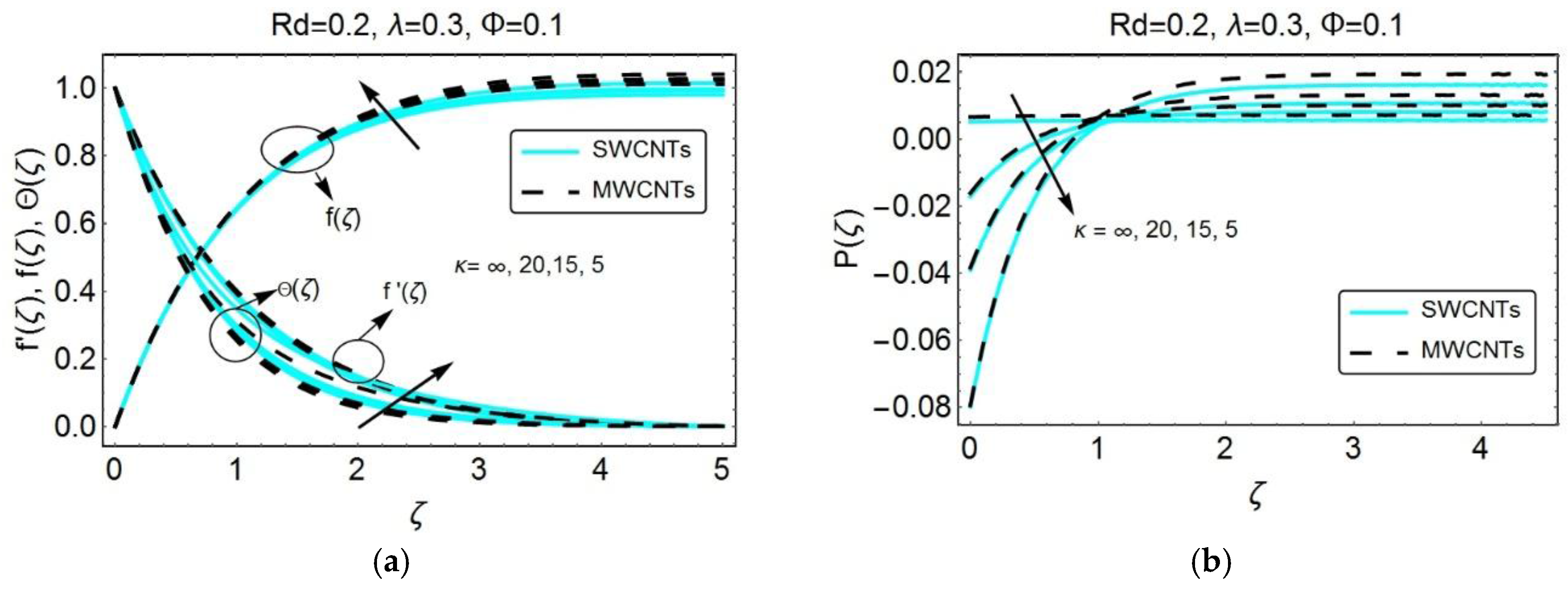
Figure 2 visualizes the effects of dimensionless curvature on the velocity, temperature and pressure profiles.
Figure 2a depicts the graphical description of the velocity profile for both SWCNTs and MWCNTs based nanofluid under the influence of dimensionless radius of curvature
. One can clearly notice an increase in the velocity as well as the momentum boundary layer thickness, with increasing dimensionless curvature (i.e., decreasing
). As the fluid particles trace the curved path along the surface of the sheet, the curvature of the sheet, under the influence of centrifugal force, enhances the secondary flow of the fluid. This flow is relatively minor, which is then superimposed on the primary flow which as a result enhances the fluid velocity.
The effect of curvature seems to be small in the
-direction, while, in the
-direction, the impact is quite prominent which is mainly due to the centrifugal force acting towards the origin.
Figure 2a also exhibits the role of dimensionless radius of curvature κ on temperature profile
. The increment of the dimensionless curvature enhances the temperature of the fluid, i.e., the maximum amount of heat is transfer when the radius of curvature decreases.
Figure 2b illustrates the influence of dimensionless curvature on the pressure profile. Clearly, a decline in dimensionless radius of curvature enhances the magnitude of pressure inside the boundary layer. However, far away from the boundary, the pressure remains almost negligible because the behavior of stream lines away from the sheet follows the same pattern of flow as in the case of flat stretching sheet. Furthermore, it is pertinent to mention that the pressure variations, near and away from the surface, seem insignificant in the case of flat stretching sheet (i.e.,
). On the other hand, the pressure does not remain constant when the curvature is employed into the sheet and, therefore, a certain variation has been perceived, especially inside the boundary layer.
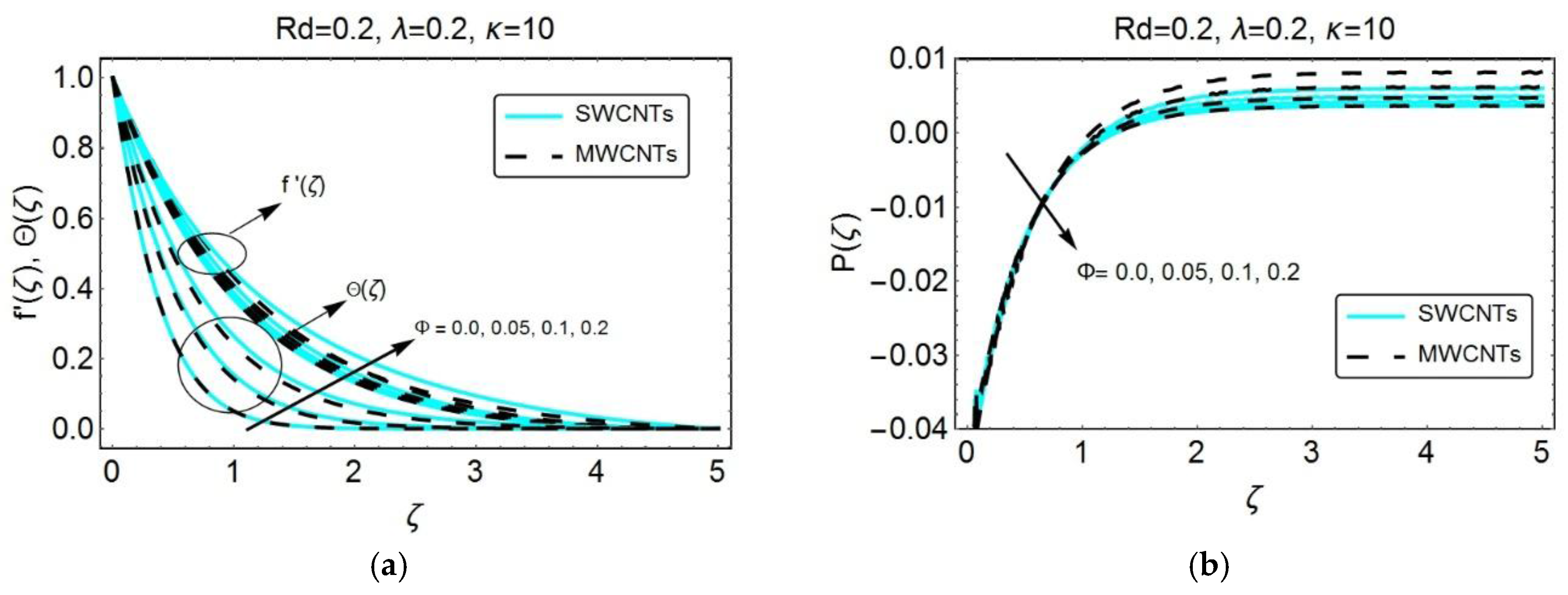
Figure 3 has been placed to show the influence of nanoparticle volume fraction
on the velocity, temperature and pressure profiles. A certain rise in velocity has been observed when the nanoparticle volume fraction increases. Besides, it has been observed that the SWCNTs have a slightly lower velocity than MWCNTs, which is due to the higher density values for SWCNTs with which the resistance within the fluid increases and consequently the dimensionless horizontal velocity component, i.e.,
, for SWCNTs decreases.
Figure 3a also shows the variations in temperature
with increasing
. The temperature of the fluid rises and consequently, the thermal boundary layer increases. Since the carbon nanotubes bear high thermal conductivity and low specific heat as compared to the base fluid, the inclusion of sufficient nanoparticles enhances the temperature of the fluid quite significantly. Moreover, the temperature for MWCNT-nanoparticles exhibits lower values as compared to SWCNT-nanoparticles.
Figure 3b depicts the behavior of pressure distribution for distinct values of solid volume fraction
. A decline has been noticed in the magnitude of pressure distribution with an increasing
.
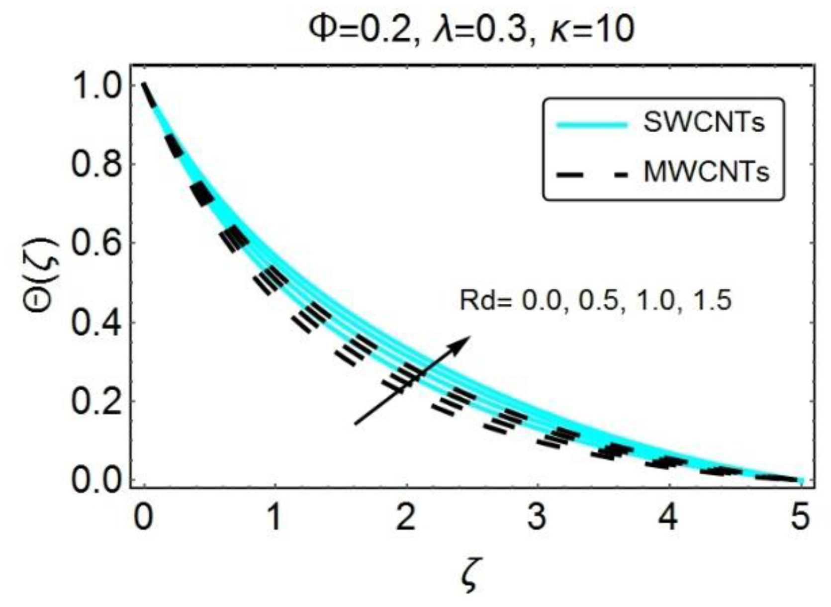
The results in
Figure 4 highlight the variations in temperature for increasing values of radiative factor
. As expected, because of radiation, nanofluid temperature raises quite significantly. The reason behind is the decline in mean absorption coefficient and as a result the rate with which radiative heat transfers seems to be increasing at every point distant from the sheet. It has also been observed that the temperature of SWCNTs-nanoparticles increases more than MWCNTs nanoparticles because of the less thermal conductivity of the MWCNTs nanoparticles.
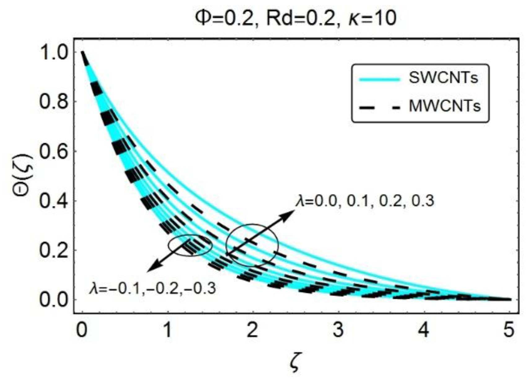
Figure 5 depicts the behavior of heat generation parameter
on the temperature profile. The increasing
causes an upsurge in temperature as well as in thermal boundary layer thickness for both SWCNTs and MWCNTs nanoparticle. The heat generation parameter usually involves the heat generation coefficient and, thus, the increment of heat generation parameters leads to an increase in heat generation coefficient which means that the temperature at the surface is higher than the free stream temperature and, therefore, by transferring the heat from the sheet to the fluid, the rise in the temperature is quite obvious. Moreover, the increment of heat absorption parameter
implies a decline in temperature in the region adjacent to the wall for both SWCNTs and MWCNTs based nanofluid.
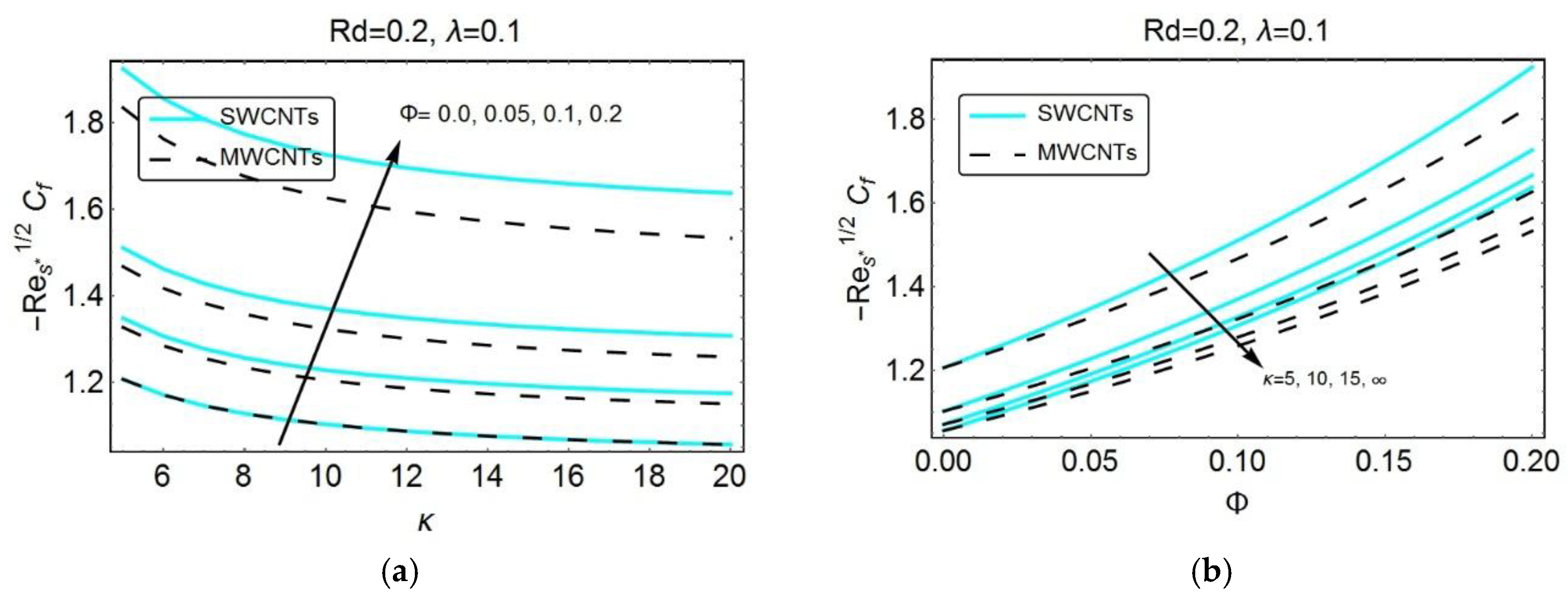
Figure 6 describes the influential behavior of various parameters on skin friction coefficient. The increment in nanoparticle volume fraction considerably enhances the magnitude of skin friction coefficient, as seen in
Figure 6a. The reason is the higher volume fraction of nanoparticles, in terms of composite carbon chains, which plays a prominent role within the fluid as well as on the surface and as a result increases the surface friction in both directions. Furthermore, it has been observed that the SWCNTs remain on the higher side because the higher density value of SWCNTs as compared to MWCNTs, therefore, the resistance within the fluid, seems to be more significant in the case of SWCNTs and thus exhibits the higher skin friction.
Figure 6b depicts the impact of dimensionless radius of curvature
on skin friction coefficient for both SW- and MW-carbon nanotubes. A decline in skin friction coefficient has been observed with the increasing values of dimensionless radius of curvature
, which indicates that the increment in
decreases the curvature of the surface and, therefore, offers a less resistance to the fluid particles which eventually decay the skin friction coefficient.
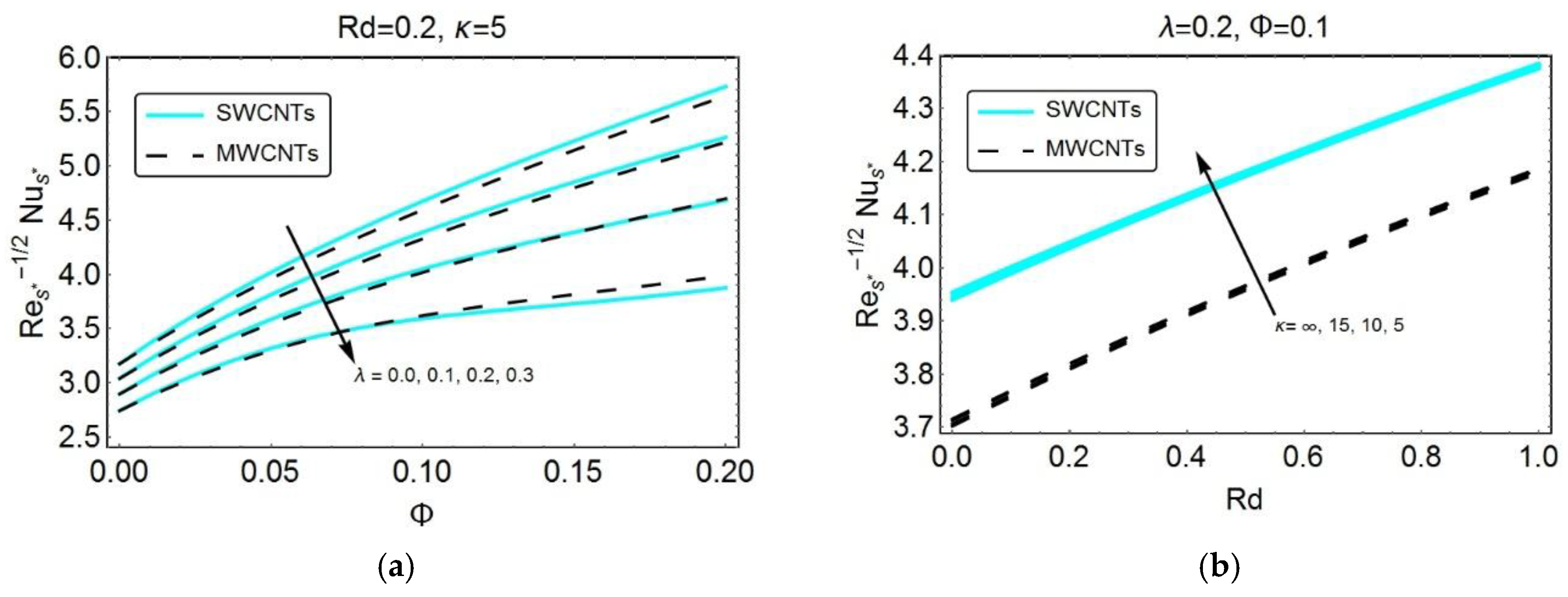
Figure 7 illustrates the effects of various parameters such as solid volume fraction
, heat generation parameter
, radiation parameter
and dimensionless radius of curvature
. on the rate of heat transfer for both single walled and multi walled carbon nanotubes. In
Figure 7a, one can clearly observe an enhancement in the local heat flux rate with an increasing nanoparticle volume fraction
for both SW- and MW-carbon nanotubes. Nusselt number is usually a product of thermal conductivity ratio and temperature gradient.The temperature gradient experiences a decline due to the inclusion of nanoparticles and it is much smaller than the thermal conductivity ratio, which as a result enhances the magnitude of Nusselt number. Furthermore, it has also been noticed in
Figure 7a that the local heat flux experiences a decline with the increasing heat generation parameter
. Since the increment of heat generation parameter significantly raises the temperature of the fluid, the decrement in the rate of heat transfer is obvious. The impact of radiation parameter
on the magnitude of the local Nusselt number is presented in
Figure 7b. It has been noticed that the rate of heat flux is an increasing function of
. The increment of radiation parameter
drastically enhances the heat transfer coefficient which as a result shows an increment in heat transfer rate. Moreover,
Figure 7b also describes the effect of dimensionless radius of curvature
on the rate of heat flux. The increment in the magnitude of local Nusselt number has been perceived with an increasing dimensionless curvature (i.e., decreasing
). Since the temperature of the fluid rises with an increasing dimensionless curvature, rate of heat flux seems to be significant with decreasing
.
Table 2 has been organized to see the variations in thermal and physical properties of base fluid with the dispersion of carbon nanotubes. It has been clearly noticed that the inclusion of both types of carbon nanotubes significantly enhances the thermal conductivity of the base fluid. The density of the fluid also increases while the specific heat experiences a clear decline.
Table 3 and
Table 4 has been organized to discover the impact of various embedded parameters on local skin friction and local Nusselt number for both SW- and MW-carbon nanotubes.
Table 3 illustrates the influence of both solid volume fraction
and dimensionless radius of curvature κ on skin friction coefficient
. In addition, comparison with the previously existing results of Abbas et al. [
44] has been presented. It has been witnessed that the skin friction coefficient experiences a decline because of increasing dimensionless radius of curvature κ which indicates that a larger drag force is required to drag the fluid over the curved stretching sheet.
Table 4 provides the numerical values for skin friction coefficient
and the magnitude of local Nusselt number
for numerous values of solid volume fraction
and heat generation parameter
under the assumption that the dimensionless radius of curvature
i.e.,
(for flat dilating sheet). It has been observed that the skin friction coefficient increases with increasing values of
, which can also be observed in
Table 3. Moreover, less resistance has been offered by MWCNTs as compared to SWCNTs. In addition, the magnitude of local Nusselt number seems to be an increasing function of
for both SWCNTs and MWCNTs. The reason is the supremacy of CNTs over traditional base fluid, i.e., water, which is primarily due to the higher thermal conductivity and low specific heat. Thus, the ability to conduct heat significantly improves the rate of heat flux at the sheet. This proves the fact that the addition of carbon nanotubes enhances the local heat flux. On the other hand, the local rate of heat flux experiences a decrement with the increasing values of
for CNTs based nanofluid as well as traditional base fluid. Finally, the validity of our results for a dimensionless radius of curvature
, i.e.,
(for flat dilating sheet), is shown in
Table 5. An excellent agreement has been found between obtained results and previously published results of Ali [
52], Grubka and Bobba [
53] and Ishak et al. [
54] in the absence of radiation parameter
, heat generation parameter
and carbon nanotubes
.

 ,
, 


