Optimization of Mass Concrete Construction Using a Twofold Parallel Genetic Algorithm
by
 ,
,
Mariane Rita
1, 
Eduardo Fairbairn
1,*,
Fernando Ribeiro
1,
Henrique Andrade
1 and
Helio Barbosa
2 1
Department of Civil Engineering, The Federal University of Rio de Janeiro (COPPE/UFRJ), Rio de Janeiro 21941-972, RJ, Brazil
2
National Laboratory of Scientific Computing (LNCC), The Federal University of Juiz de Fora (UFJF), Juiz de Fora 25651-075, MG, Brazil
*
Author to whom correspondence should be addressed.
Appl. Sci. 2018, 8(3), 399; https://doi.org/10.3390/app8030399
Submission received: 24 January 2018
/
Revised: 26 February 2018
/
Accepted: 3 March 2018
/
Published: 9 March 2018
(This article belongs to the Special Issue Modelling of Early Age Cracking Risks and Serviceability of Concrete Structures)
Abstract
:This paper presents a solution strategy, based on a parallel Genetic Algorithm (GA), to optimize the construction of massive concrete structures. The optimization process aims at minimizing the construction cost, considering the following design variables: the concrete mixes, the placing temperature, the height of the lifts, and the time intervals between placing the lifts. The cracking tendency is taken into account by a penalty scheme imposed to the fitness function of the GA. A thermo-chemo-mechanical model is used to calculate the transient fields of hydration, temperature, stress, strain, and cracking tendency. This model is implemented in a finite element code that is, in turn, parallelized. To demonstrate the efficiency of the proposed methodology, the simulation of the construction of a structure similar to the real thick foundation of an industrial building is presented. It shows that the optimization procedure here presented is feasible and is ready to be used in real engineering applications.
1. Introduction
When a dam or any other massive concrete structure is designed, most of the characteristics that will determine the mechanical behavior are defined, such as geometry, vertical joints, reinforcement, concrete strengths and zoning [1]. In general, as the construction site is planned and organized, a formwork system is chosen and an ice production unit is implemented in the jobsite. After that, before the beginning of the construction, the construction management team performs studies aiming to define suitable concrete mixes and carrying out tests to determine the main thermo-chemo-mechanical properties of these materials. Depending on the importance of the construction, local standards, and technologies available, these studies will be more or less thorough. In general, the thermal properties (thermal capacity, thermal conductivity, coefficient of thermal expansion) and hydration properties (adiabatic or semi-adiabatic temperature evolution) are determined for one or more mix designs in use for the structures at hand.
Therefore, when massive concrete structures such as spillways, power houses, transition walls, or deep foundations, are about to be built, few variables are yet to be determined to carry out the construction of the structure. Since, in general, massive structures are built lift-by-lift in successive concrete layers these variables are [2]: (1) The thickness of the lifts; (2) The time interval between the placement of lifts; (3) The placing temperature of concrete; (4) The mix design of concrete.
As a matter of fact, the concrete proportions are established in an optimized way that minimizes cement content, minimizing the effects of the heat of hydration. Therefore, it is not uncommon to have just one mix design available. In this way, depending on the type of construction, the set of variables is reduced to just the three first variables described above. The choice of these variables is governed by the risk of cracking induced by hydration heat and by the costs associated with them.
It should be stressed that several other parameters intervene in the development of stresses induced by hydration. Factors that may be mentioned, for example, are the degree of restriction imposed by the foundation, the formwork system and its thermal characteristics, the evolution of the environmental temperature and wind, etc. However, these parameters are not, in real case applications, at the time of the beginning of construction, a choice for the construction management team and they should be considered as fixed given parameters. Another possibility of varying the thermal stresses at the early ages is the use of a post-cooling system using tubes which can be filled with running water or air [3]. In the present paper such systems are not considered as variables of the optimization problem. However, at the present stage of the development of the optimization procedure, they can be considered as given fixed parameters of the structure.
In view of the above considerations, the optimization problem treated in this paper can be stated as: “Find the type of concrete, the placing temperature, the height of the lifts and the rhythm of construction that minimize the construction cost of a massive concrete structure with the constraint that thermal cracking is not allowed”.
In this way, individual construction plans must be evaluated. This is achieved by simulating the phased construction of the structure and choosing the suitable set of variables that avoid cracking originated by the heat of hydration.
The simulation of the thermo-chemo-mechanical problem can be performed with the use of numerical models, generally based on the finite element method (FEM). Such models may range from simplified approaches to sophisticated thermo-chemo-mechanical models. One can refer, among others, to the works of Cervera et al. [4], Luna and Wu [5], Lackner and Mang [6], Fairbairn et al. [7] and Azenha et al. [3]. A recent survey of these models can be found in [8].
It is nowadays well accepted that a model that is supposed to simulate the evolution of the stresses of massive concrete at the early ages should consider the couplings between the evolution of the hydration reaction, the properties of the materials, and the transient thermal fields. The consideration of all these phenomena leads to highly nonlinear models with a large computational cost. In addition, the simulation of structures that have often a complex geometry may generate models with a large number of degrees of freedom, further increasing the computational effort. With this in mind, a computer code that encompasses a thermo-chemo-mechanical model based on Ulm and Coussy’s model [9,10] was developed within a finite element code with a parallel architecture. Such code allows for the analysis of real-world structures in their construction phase taking into account the several physical and geometrical complexities that intervene in the problem [7,11].
Although several references can be found on the use of artificial inteligence algorithms applied to dams and concrete structures [12,13,14], only a few concern the phased construction of massive concrete. A first approach using serial Genetic Algorithms and serial FEM computer code was done in the early 2000s [15]. It was applied to the construction of a small hydropower plant. The approach proved to be accurate but the case study had to be limited to a very simple structure due to the high computational cost of running such problem in sequential architectures.
In the present paper the optimization of the construction phase of massive concrete structures was improved by means of a two-level parallelized scheme. On the lower level the thermo-chemo-mechanical model is implemented in a parallelized FEM computer code [16] while at the higher level the fitness function of the Genetic Algorithm (GA) is computed in a parallel environment [17].
The speed-ups obtained by this twofold parallelization scheme allow the optimization of real case massive concrete structures which was impossible in practice due to computational time. Thus, from now on it is possible to automatically determine the optimal variables for the construction of a real massive concrete construction in a feasible computational time ensuring that the structure will not present thermal cracks.
The case study here presented demonstrates that this methodology allows for the optimization of real-world engineering problems considering most of the physicochemical phenomena and geometrical complexities that intervene during the construction phase of massive concrete structures.
2. Principles of the Thermo-Chemo-Mechanical Numerical Model
Ulm and Coussy’s model has been described in detail elsewhere [9,10,18,19,20]. Therefore, in the present paper only the equations necessary to understand the optimization process are presented.
The equation for the transient thermal and hydration fields that expresses the thermo-chemical coupling is:
where: c is the specific heat; is the density; T is the temperature; represents the heat generated by the exothermic reaction, being a material constant. is the degree of hydration, a normalized variable that accounts for the evolution of the hydration reaction, and k is the thermal conductivity.
The chemo-mechanical coupling is represented, in a simplified form, by the following equation:
where: is the stress tensor; is the strain tensor; is the thermal dilatation coefficient; is the variation of autogenous shrinkage strain, considered, for the sake of simplicity, linear with the variation of the hydration degree; is a material constant; and is the elastic compliance tensor, dependent on the degree of hydration. As Poisson’s ratio is considered to be constant with the degree of hydration, one can write, formally, .
Therefore, for a given point of the structure, and for a given time, the cracking index, that represents the cracking tendency at this point, can be written as:
where is the maximal positive principal stress and is the tensile strength of the concrete.
It should be stressed that the cracking index is always computed in the elastic range even if it is greater than 1, i.e., even if the tensile stresses exceed the tensile strengths. This strategy was used because, within the framework of the optimization process, there is no need to precisely compute the post-cracking behavior (cracking evolution) of the structures at hand. The cracking index is just a parameter that is used to penalize sets of variables that tend to crack the structure at the early ages for the first generations of the GA. For the last generations and for the best case, the structure does not present any element where the strength is reached. In this way cracking indexes greater than 1 do not have a precise physical meaning and there is no need to use a sophisticated microcracking model that simulates the very complex damage evolution of cracked concrete.
This numerical model was implemented in a massively parallelized 3D FEM code using linear tetrahedral elements. It is composed by two modules: thermo-chemical and mechanical. The code allows for the simulation of a layered construction, i.e., the geometry of the structure may change to simulate the sequential pouring of the several concrete lifts. The parallel implementation is designed for a distributed memory architecture and the data structure known as compressed storage row/columns (CSRC) is used to store the coefficient matrix and obtain iterative solutions, in a subdomain-by-subdomain approach (SBS) using the method of preconditioned conjugate gradients (PCG) [16,21].
3. Optimization Problem of the Construction Phase of a Massive Concrete Structure Using a GA
Genetic Algorithms are computational methods inspired by Charles Darwin’s theory of natural evolution which provide a parallel and adaptive search mechanism commonly used to generate high-quality solutions to optimization problems. The classical GA were first proposed by Holland [22] and described by Goldberg [23]. It is based on the simulation of the evolution process of individual populations (chromosomes) using operators such as mutation, crossover and selection to find the optimal solution for the problem. The use of the GAs for structural optimization problems is generally suitable due to three main reasons [24]: the ability to find a global optimal solution; the discrete nature of the design variables; and the ease for imposing constraints by means of penalty schemes.
Genetic Algorithms require the evaluation of population individuals (potential solutions for the problem) during the entire evolution process. For the problem at hand this evaluation implies running a nonlinear finite element model and this can result in a high computational cost. It was then decided to implement a twofold parallelization scheme in such a way that the several individuals (FEM evaluations) are run in parallel and the FEM itself is also parallelized. In the next subsections this strategy is described in more detail.
3.1. Design Variables
The design variables considered for the optimization of the construction phase of massive concrete structures can be described by the following discrete set : the type of concrete , the placing temperature , the height of the lifts , and the placing frequency . Thus, the vector of design variables is defined as:
The adequate choice of the type of material is very important because it directly influences the evolution of the hydration reaction and the development of the mechanical properties. As an example, the addition of pozzolans and lower cement consumption can greatly reduce the heat generated by the hydration reaction.
The placing temperature of the concrete is directly related to the maximum temperature reached in the structure and also to thermo-activation, which is responsible for the kinetics of the hydration reaction. Otherwise, the lower the heating rate of the structure, the more the heat will dissipate through the boundaries. Therefore, the thermal gradients will be lower, and the risk of cracking will be lower. In this paper the maximum placing temperature is limited to the average environmental temperature, and the minimum placing temperature should be defined by the contractor according to the cooling facility available in the field.
The height of the lifts influences the dissipation of the heat generated by the hydration reaction. Then it is related to the maximum temperature that the concrete will reach, as well as with the time of construction. For higher values of , the lower is the construction cost, due to the reduced construction time. However, the risk of cracking increases due to the reduction in heat dissipation in a more massive structure. For the sake of simplicity, this paper considers that the lifts have the same height, except for the highest lift whose height is the one required to reach the total height of the structure . Thus, the total number of lifts is given by:
where represents the integer part of x.
The placing frequency is the time interval between the placing of a lift and the subsequent one. This variable is directly related to construction time and hence its cost. On the other hand, increasing the placing frequency allows for the dissipation of hydration heat and the development of the mechanical properties of the lifts that had already been built.
Therefore, the construction time can be calculated by the following expression:
where is the time required for finishing the construction after placing the last lift.
3.2. Fitness Function
The fitness function can be written as:
where stands for the normalized cost and is the penalty function introduced to penalize cracking. It should be noticed that it is a dynamic penalty function, as it depends on the current generation, , of the Genetic Algorithm.
Considering that the geometry of the structure is given, and consequently its volume, the cost function can be understood as a volumetric construction cost expressed by:
where , , and are normalized volumetric costs () for, respectively, concrete, cooling, and operation; and are weigths, such that . According to Fairbairn et al. [15], the values of these weights depend on factors, such as, the type of construction, local conditions, variations in the unitary costs, etc. However, regardless of the uncertainty of these unitary costs, it is always possible to estimate them when the construction is being planned. The cost function is bounded by the limits:
where is the minimum value that can be reached by , regardless if the structure cracks or not, and can be easily calculated using an adequate set of variables .
The cost of the concrete can be computed by summing the costs of its components, such as binders, water, aggregates, and chemical additives.
The cost for cooling the concrete depends on many factors, such as the type of building, the construction site, and the availability of the facilities to produce ice. The higher the placing temperature, the lower the cost, and this cost is zero when the placing temperature is the ambient temperature.
The operational cost is an increasing function of the construction time . The evaluation of this function is not an easy task and should be done on the basis of the experience of the contractor. For the sake of simplicity, the following linear function was used to represent the normalized operational cost:
3.3. Penalty Function
Penalty functions are generally used to prevent the appearance of non-feasible solutions in constrained optimization problems. The choice of the appropriate penalty is extremely important to obtain good results. It is known that a very aggressive penalty can lead to loss of good genetic material, while a very soft penalty can perpetuate poor schemes that do not introduce relevant information to the evolutionary process.
In this work, it is considered that a solution is not feasible if the structure cracks. Aiming to properly characterize cracking of a structure, it is worthy to characterize cracking at a given point. It should be stressed that, at the early ages of a structure, a given point may have cracks opened and closed for different times. Therefore, within the framework of the present analysis, for the sake of simplicity, a point is considered as cracked if, for at least one time step, the point experiences cracking.
In this way it is worthy to introduce the variable , which is defined as: if for all the time steps of the analysis and if for at least one time step of the analysis. Therefore, it can be written that .
In the present paper the FE model uses linear tetrahedrals with one integration point. Therefore the variable can represent cracking of a given finite element, i.e., . It is now possible to introduce a variable that stands for the global (macroscopic) cracking tendency of the structure () that is equal to the sum of the volumes of the cracked finite elements (i.e., the elements that have ) divided by the sum of the volumes of all elements. Considering that the cracking of an individual structure is a function of the set of design variables () that characterize this individual, the following equation can be drawn:
where is the total number of finite elements, and is the volume of a given finite element.
The penalty scheme combines a dynamic penalty for the early generations and a static penalty for the late generations. This scheme allows for a greater diversity within the first generations (the half of the evolutive process) accepting the survival of individuals with a small extent of cracking. For the late generations only uncracked individuals are allowed to survive, a condition that is established by the penalty scheme proposed.
The dynamic penalty is defined as follows.
Let be an initial extent of cracking that determines the limit of cracking in the initial population; let be the function that evaluates the cracking limit according to the current generation ; and let be the number of generations. The extent of cracking can be written, for each generation, as:
The penalty function can then be written:
Some characteristic values of the fitness function that help to understand the organization of the penalty scheme are given in the Equation (14).
3.4. Parallel Genetic Algorithm
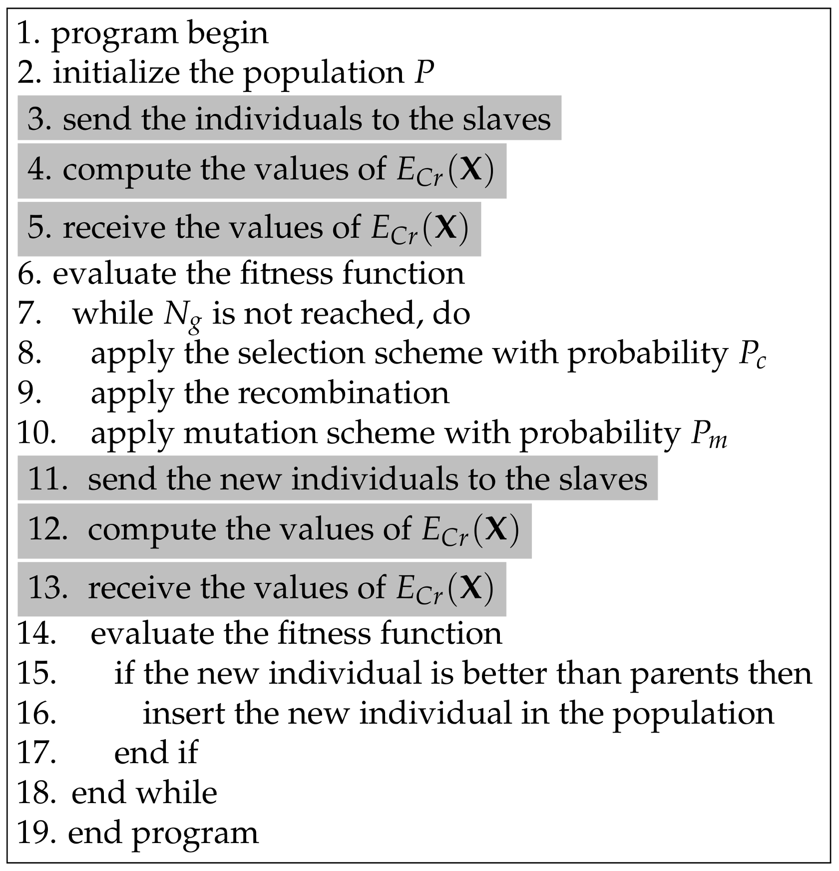
A pseudo-code of the optimization procedure is displayed in the Figure 1. The parallel Genetic Algorithm follows the main strategic principles of a sequential algorithm, however it makes use of a parallelized master-slave model that manages the calculation of the extents of cracking by running independent FEM analysis in each cluster node. The GA follows the generational model that replaces the old population by new individuals. However, an insertion criteria was adopted for which the new individuals will replace the old ones only if they are better evaluated. The genetic operators used are the tournament selection scheme, two-point crossover, and simple mutation ([22,23,25]).
The control parameters that should be adjusted for the good performance of the model are: the population size indicating the number of chromosomes for each generation, which is assumed constant during the evolution process; the crossover probability , which indicates the number of individuals that are selected as progenitors that participate in the recombination process; the mutation probability that commands the mutation procedure and, in this case, it produces a minor perturbation in the chromosome changing one randomly selected gene; the tournament size for the tournament selection , which helps to prevent stagnation, and, finally, the maximum number of generations, which is the algorithm stop criterion .
The individuals of the initial population are generated randomly using a procedure of pseudo-random number generation that starts from a given value called seed. Due to their stochastic nature, the results of a Genetic Algorithm analysis will only be reproduced using the same seed.
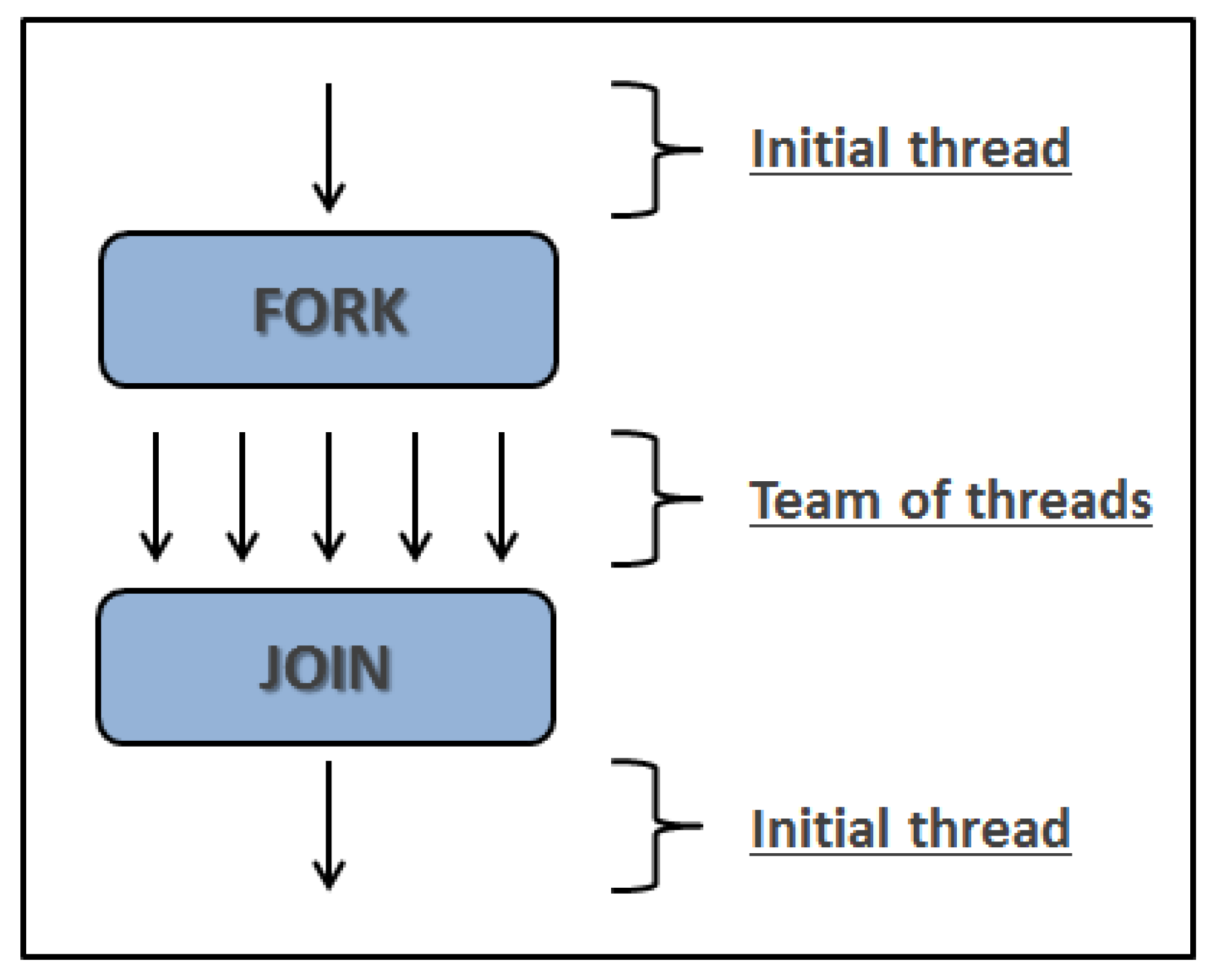
For the parallelized steps (highlighted in Figure 1), the Applicative Programing Interface OpenMP is used for the parallel implementations. Within this programing model, known as fork-join (see Figure 2 based on [26]), the program begins as a simple process that is called the master thread (initial thread). The master thread runs sequentially until the first parallel region is encountered. At this point, the master thread creates a set of parallel threads (team of threads). This process is called “fork”. Thus, the commands inserted in the parallel region are ran in parallel by the different threads created. When the threads complete the statements in the parallel region, they synchronize and terminate, leaving only the master thread. This process is called “join”.
It should be stressed that, as the main computational effort of the GA is the calculation of the extents of cracking by the FEM analysis, the FEM code is also a parallelized program which is ran in several processes within each cluster node, thus characterizing the two-level parallel procedure referred to above.
4. Case Study
This section presents a case study to demonstrate the feasibility and effectiveness of the optimization procedure here described. The example was elaborated based on the experience of the authors in the analysis of the construction phase of a number of massive concrete structures such as hydroelectric and nuclear power plants [7,11]. It has been very common, during the construction of such massive concrete structures, that the contractor demands to run several simulations varying the main parameters . That leads to a laborious process of trial and error involving simulation, analysis of results, and redefinition of the input variables until a solution that is believed to be optimal was obtained. In this way, the case study here presented attempts to reproduce as realistically as possible the engineering issues that happen during the construction phase of a massive concrete structure.
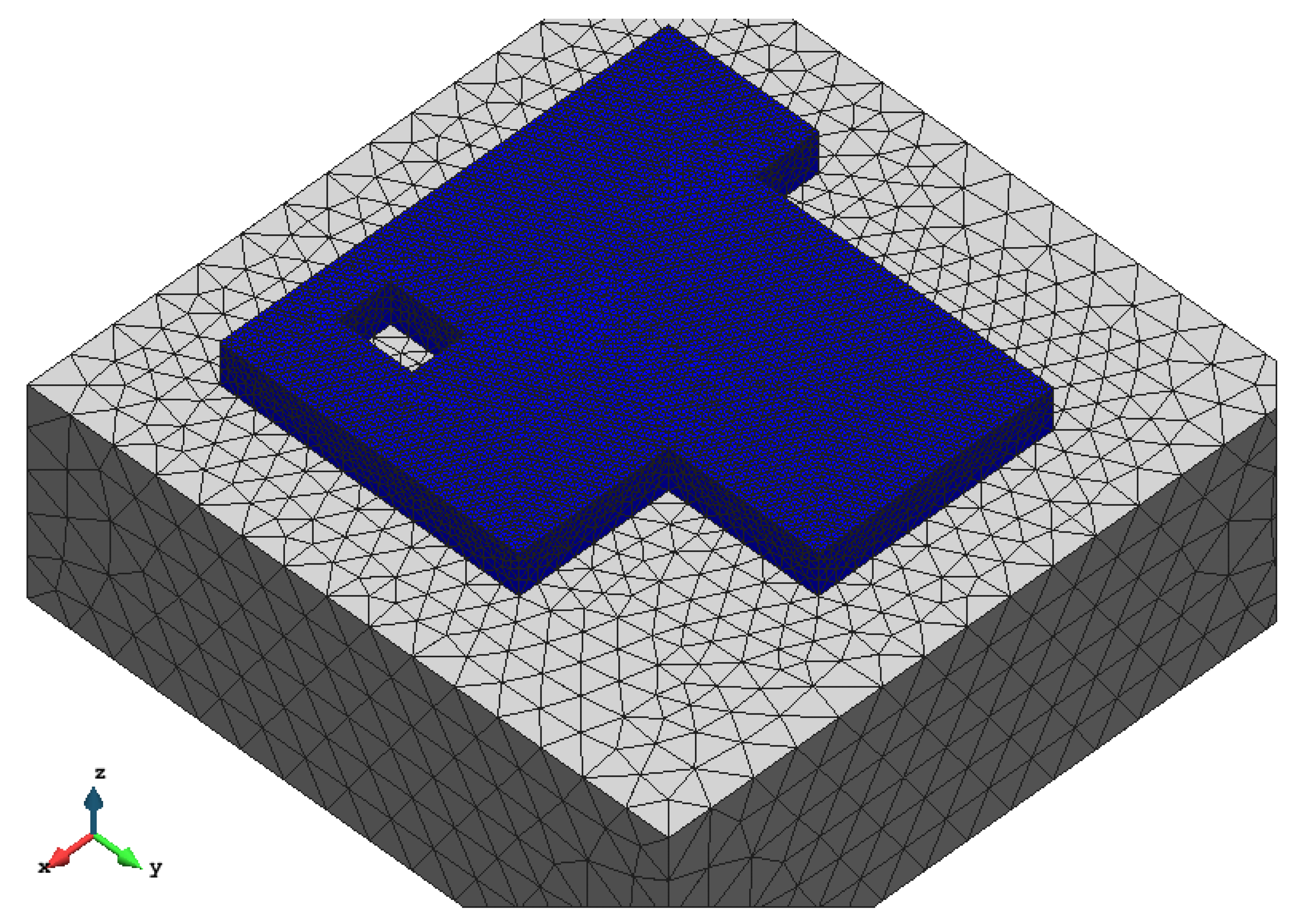
The structure chosen for this case study is similar to the thick foundation of an accessory building of a nuclear power plant. The dimensions of the parallelepiped circumscribing the concrete foundation are: 20 m × 20 m × 2 m corresponding to a total volume of concrete of 682.5 m. The concrete foundation is placed on a rock whose dimensions are assumed to be 30 m × 30 m × 10 m. A sketch of the geometric characteristics of the structure together with the finite element mesh composed by 124,459 linear tetrahedrons and 25,198 nodes is shown in Figure 3.
4.1. Design Variables
The design variables are the following:
The type of concrete : Four typical massive concrete mixes, taken from the data bank of the Laboratory of FURNAS [27], were elected as the possible choices for the present case study. FURNAS is the company responsible for the generation and distribution of electricity in the southeastern region of Brazil. Its data bank comprises comprehensive thermo-chemo-mechanical studies of more than 260 massive concrete mixes from some of the most important hydroelectric power plants in the world [28].
The composition of each concrete is presented in Table 1.
The main chemical properties, which drive the hydration reaction of the several concretes are:
(a) The activation energy , which was considered as constant for all materials:
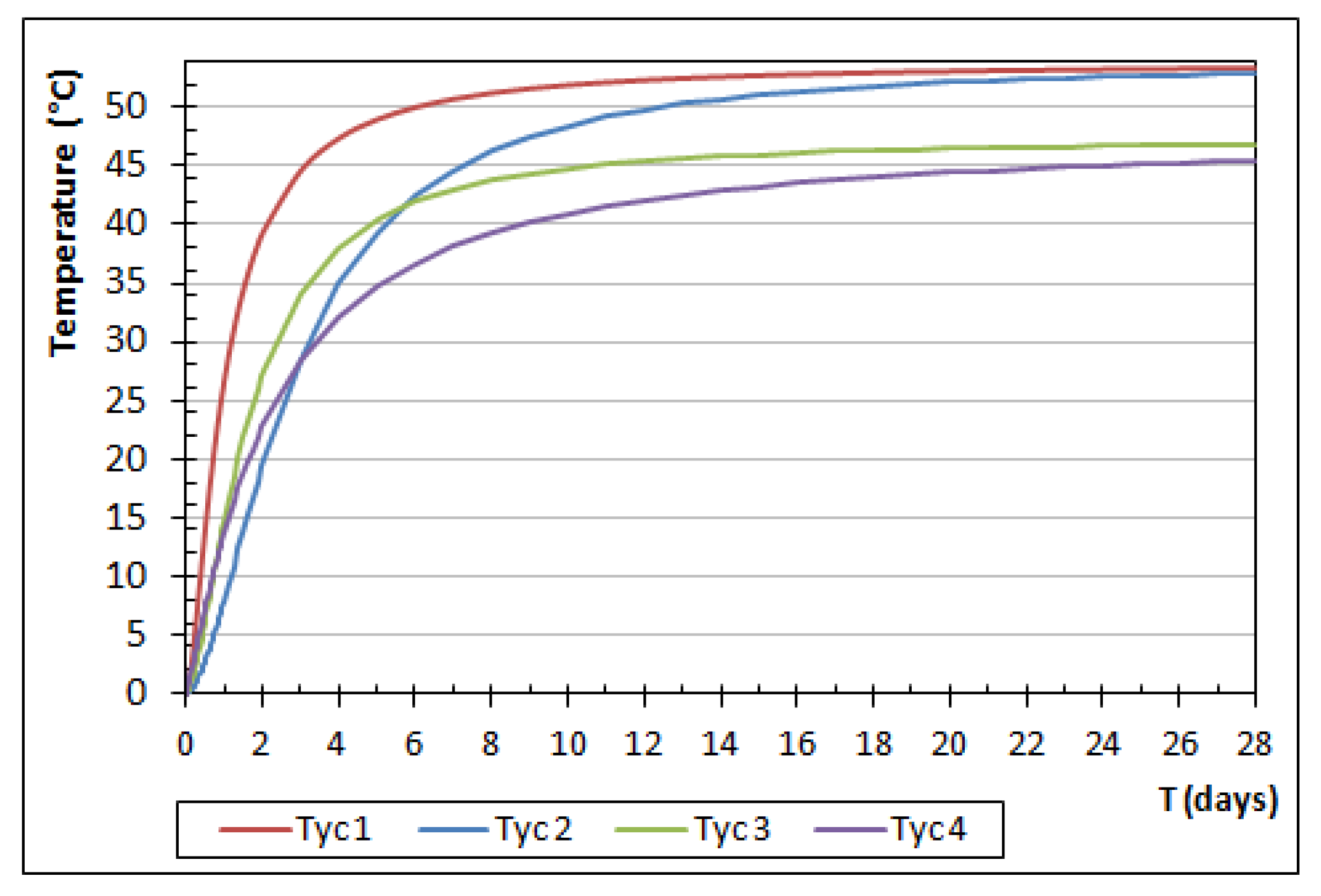
(b) The normalized affinities, which were derived from the adiabatic temperature rise curves obtained from the data bank referenced in [28] (see Figure 4). The derivation was carried out using the equation which govern the problem in adiabatic conditions (see [14] for details).
The thermo-mechanical properties are displayed on Table 2, where , and are, respectively, the tension strength, the compressive strength, and the Young’s modulus for complete hydration.
The placing temperature: the set defining the placing temperatures was defined as composed by 16 possible discrete placing temperatures. The minimum possible cooling temperature was considered to be C and the highest temperature was taken as the environmental average temperature, C. Therefore, the set of possible placing temperatures can be written as:
The height of the lifts: the following values were adopted for the height of lifts:
Each height implies a corresponding number of lifts, which is estimated according to Equation (5). Thus, the total number of lifts for each height is given by, respectively:
The placing frequency: the time required for treatment of the horizontal joints and also for dissipation of the heat released by the hydration reaction determines the placing schedule for pouring the subsequent lifts. For the case study here presented the following frequencies were adopted for placing the concrete lifts:
4.2. Unitary Costs
The costs for producing the four types of concrete (per cubic meter) were computed on the basis of the costs of its constituents. These costs were normalized by the higher cost of type 2 concrete and are given bellow:
The relation between the placing temperature and the cost for cooling the concrete is difficult to quantify and depends on a number of factors that are particular to the construction site and to the type of construction. For the present application a second order polynomial tendency curve was used, based on the experience of [7,11,15]. The unitary costs for the several cooling temperatures are displayed in Table 3.
The operational cost is computed for each individual by Equation (10) considering the construction time of this individual.
As it was shown in Equation (8), the unitary costs are weighted to consider the importance of the individual costs in the final cost. These weights, as well as other variables used in the optimization process, can be established either on the basis of a detailed budget, or determined from not-so-accurate forecasts deduced from the experience of the design and construction teams. The weights used in the present case study are nominal and were taken as:
Although these weights are hypothetical, they indicate a great difficulty in producing ice at the construction site, as well as a great importance in reducing the construction time. This may happen, for example, in hydroelectric plants, when the rhythm of construction allows for the anticipation of the beginning of energy generation.
Using the design variables and the weights described above, it was possible to determine the normalized minimum construction cost . It was obtained for the variables regardless of whether or not this structure cracks.
4.3. Control Parameters of the GA
The parameters that control the GA are: (population size), (number of generations), (crossover probability), (mutation probability) and (number of individuals in each tournament selection). Besides these parameters, the initial extent of cracking was taken as . It indicates that individuals in the initial population with extent of cracking less than will be subject to the dynamic penalty.
4.4. Results
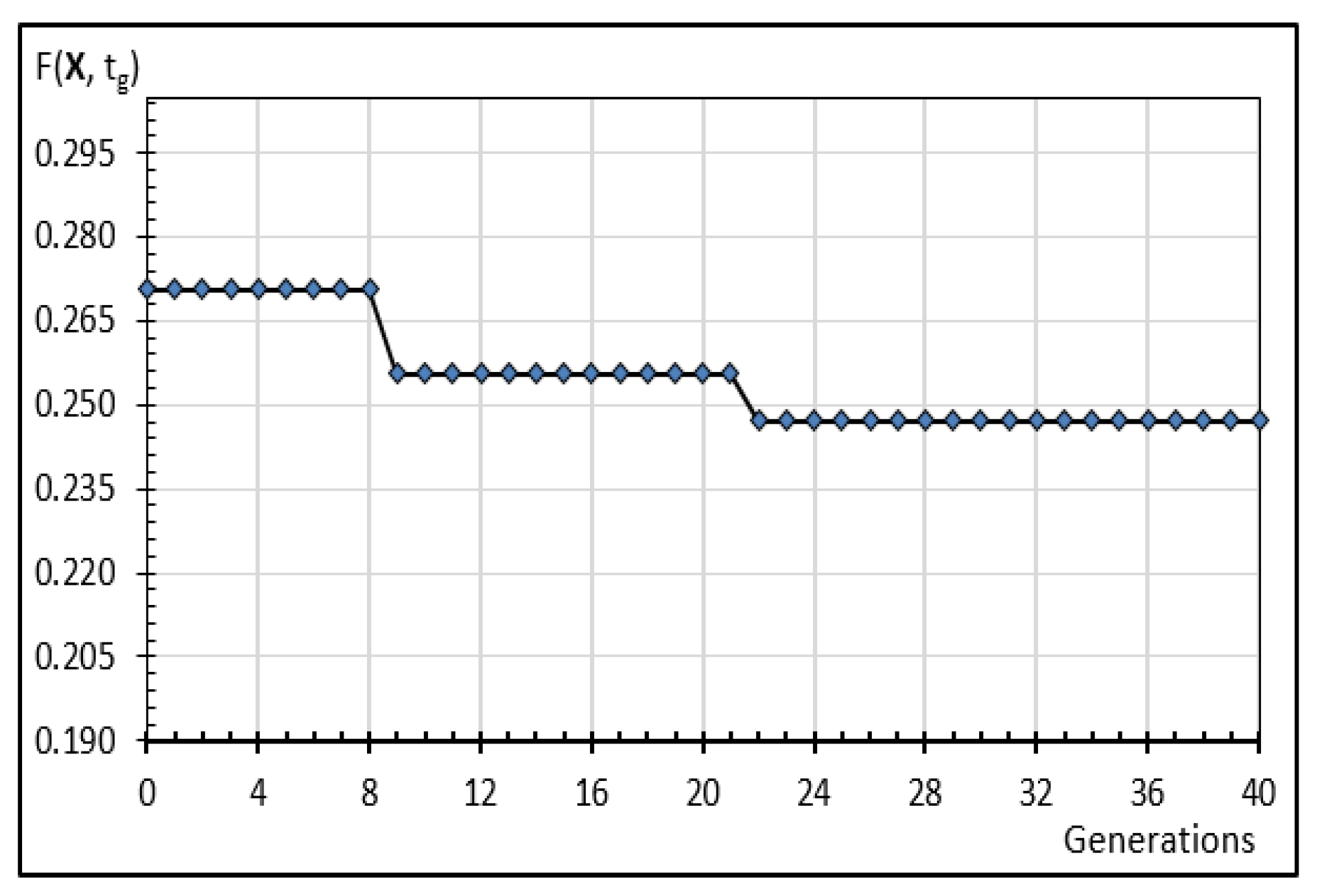
Figure 5 shows the evolution of the generations in terms of the best individuals. The optimal individual was found in the 22nd generation with fitness function of . Indeed, as imposed by the GA used here, this optimal individual corresponds to an uncracked structure.
The design variables that correspond to the optimal solution are:
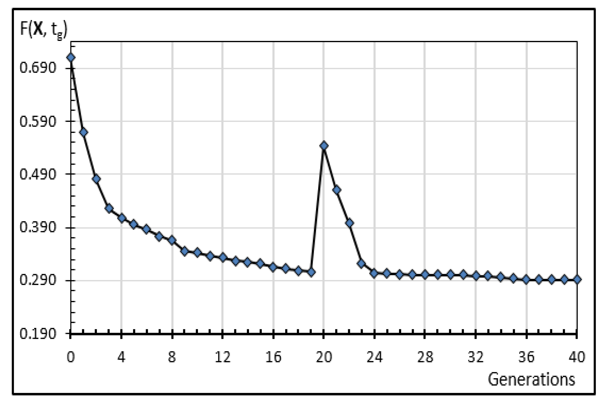
Figure 6 shows the evolution of the average fitness. It is always decreasing, except in the half of the evolutive process (generation 20) when the penalty scheme changes.
The standard deviation of the fitness function for the initial population is equal to while for the last generation it is equal to , showing that, as expected, the populations are more homogeneous at the end of the evolutive process.
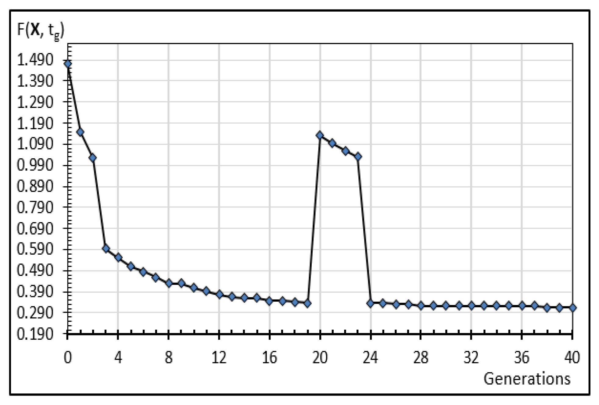
Figure 7 shows the evolution of the worst individual. As with the average fitness, there is a jump in the middle of the evolutive process due to the change in the penalty scheme.
To illustrate the thermo-chemo-mechanical behavior of the structure analyzed in this paper, some significant results are presented in the sequel.
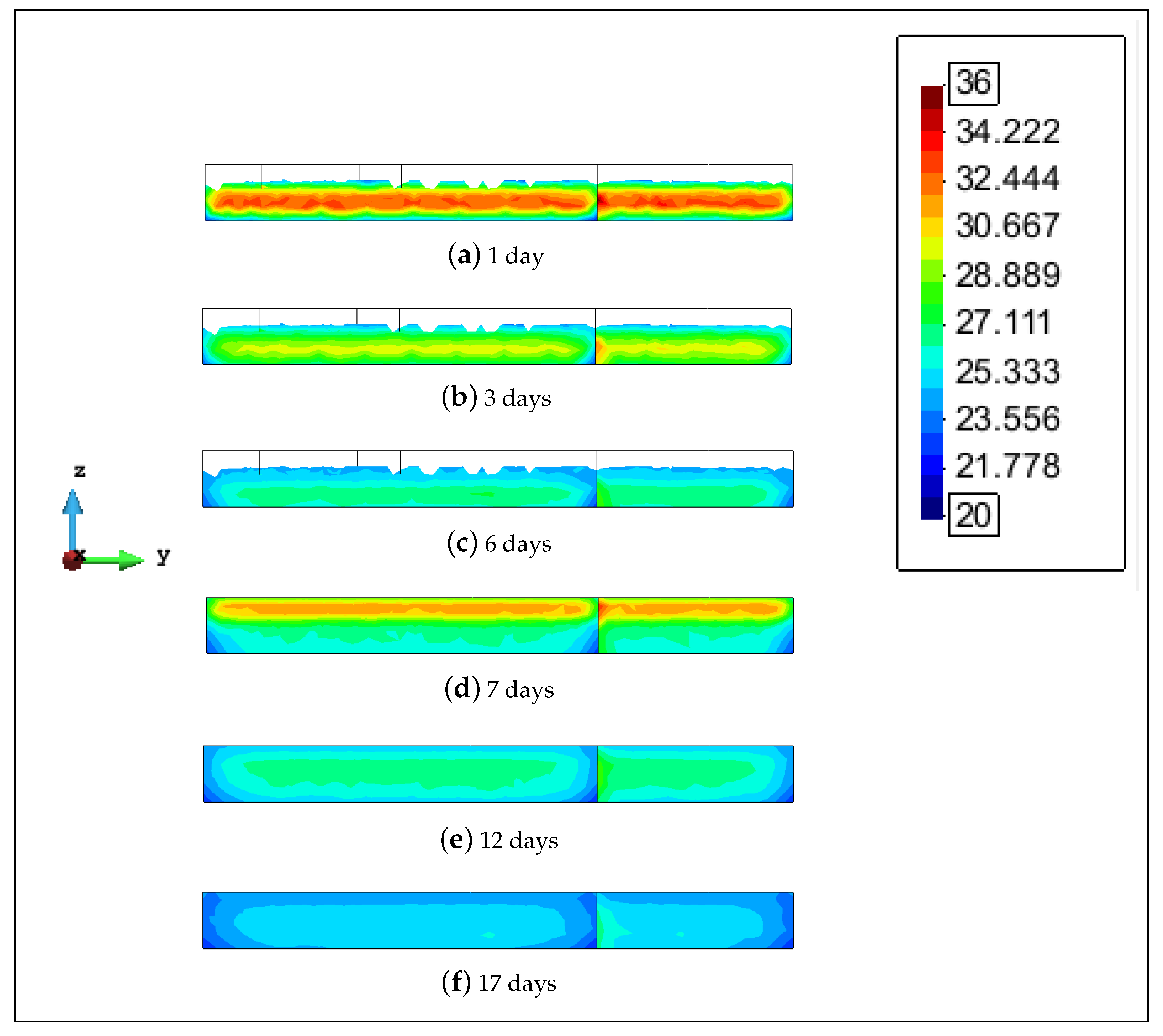
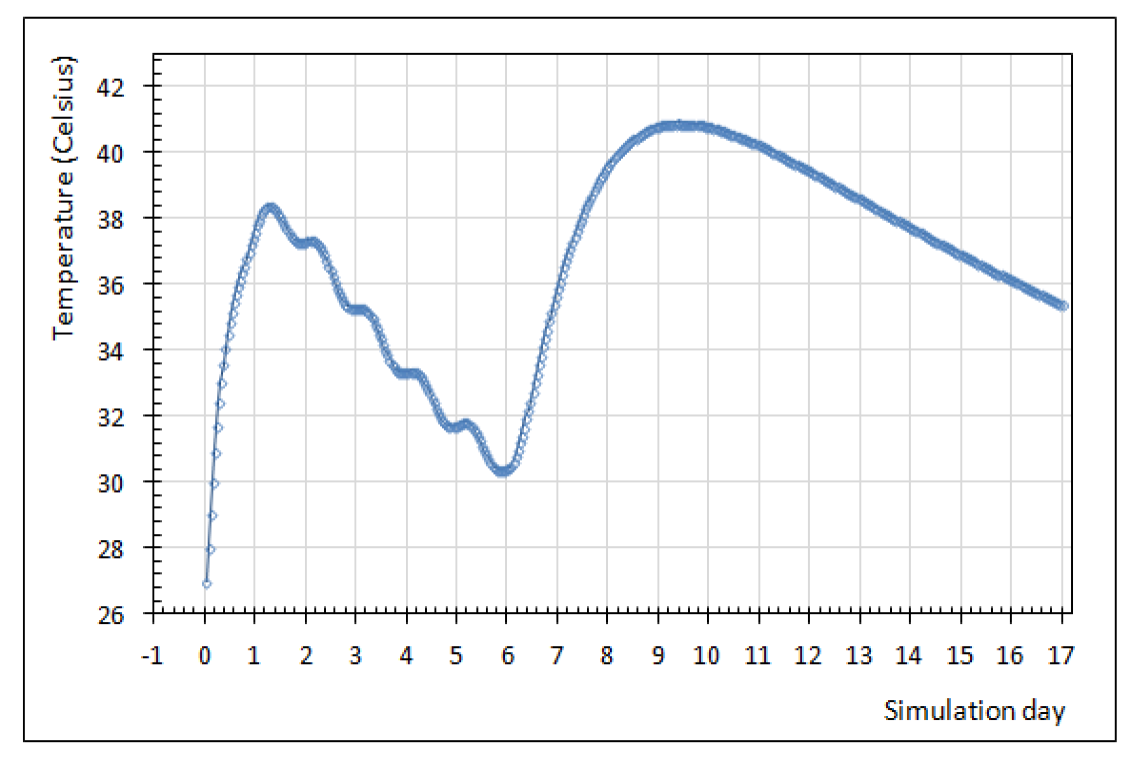
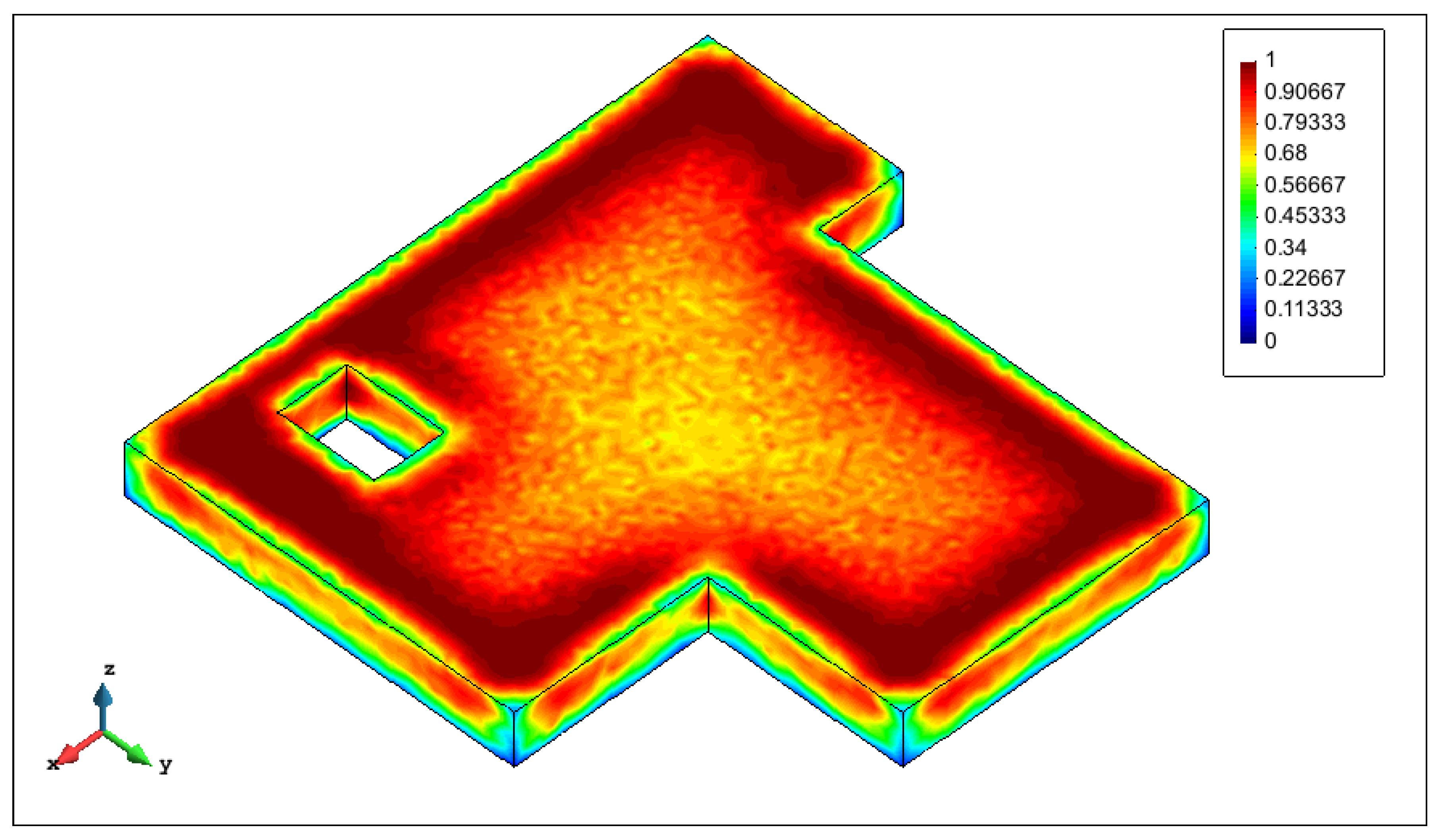
The thermal fields for the ages of 1, 3, 6, 7, 12 and 17 days corresponding to the optimal solution are given in Figure 8. Figure 9 shows the temperature evolution in a node at the center of the structure, where it is very well represented the placing of the second lift. Figure 10 shows the cracking index field for the optimal solution, indicating that the structure remains uncracked, while Figure 11 shows the cracking index field for the structure with the minimal cost, indicating a great amount of cracking.
4.5. Speedups
The parallel Genetic Algorithm runs on a computer cluster consisting of 10 computers (nodes), in which each node consists of two XEON processors E5620 QuadCore, codename Nehalem EP/Beckton, having 16 Gb of RAM. The nodes are interconnected through a high performance network InfiniBand DDR and the operating system is the CentOS 5.4.
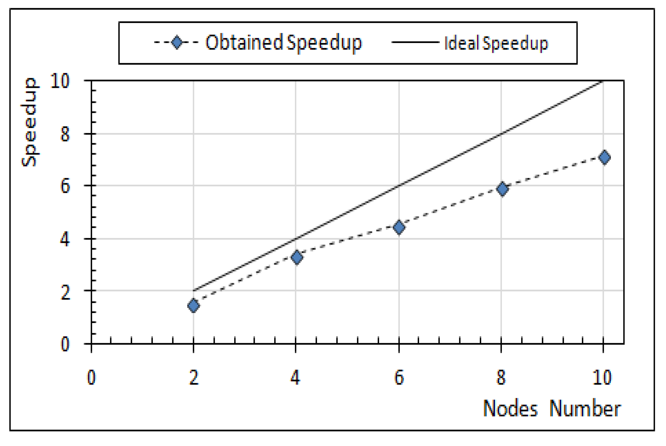
To quantify the efficiency of the optimization procedure, two measurements of speedup were used. The first one refers to the speedup of the GA alone, maintaining constant the runtime of the FEM program in eight processes for each cluster node. This speedup is defined as the ratio between the GA sequential runtime, i.e., its execution in one cluster node, and the GA runtime in n cluster nodes. The result is presented in Figure 12.
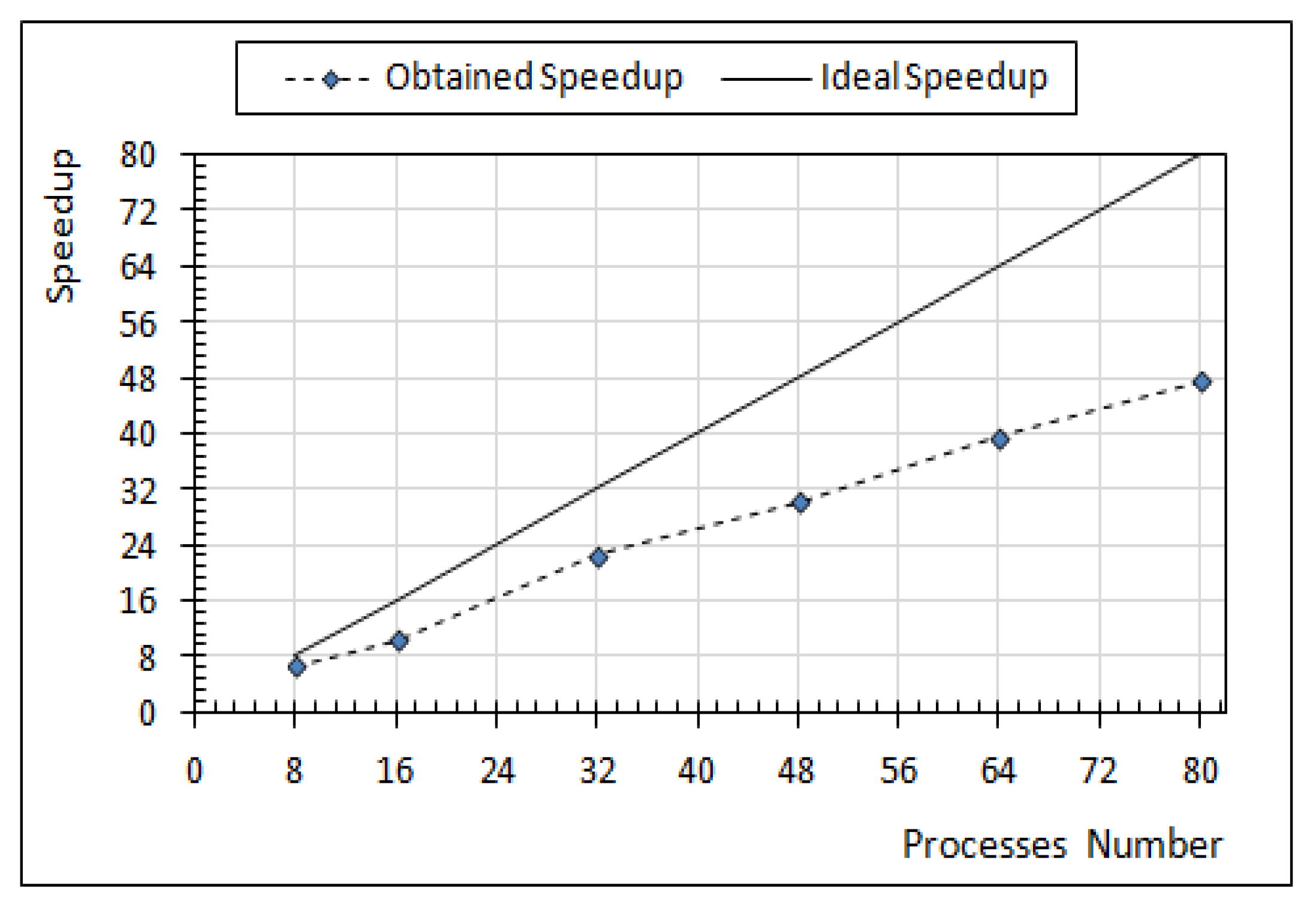
The speedup of the two-level parallelization scheme was measured by the ratio between the runtime of the GA in one cluster node, with the FE program executing sequentially in a single process, and the runtime of both programs running in parallel. Figure 13, displays this speedup as a function of the number of processes.
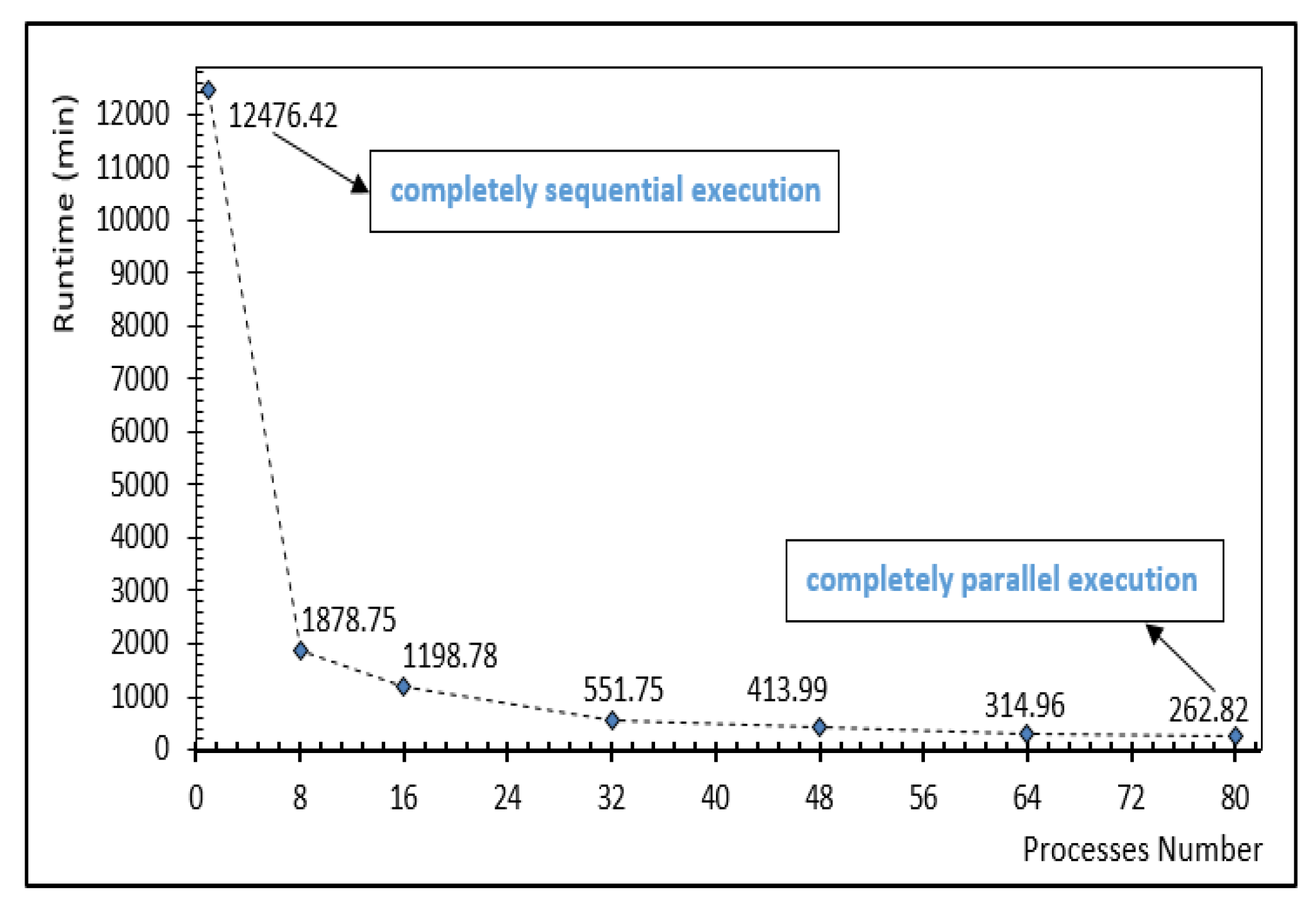
Figure 14 shows the program run-times as a function of the number of processes. It can be seen that, for a completely sequential scheme the program runs in approximately days while when fully parallelized it runs in approximately h.
4.6. Validation
The validation of the optimization procedure was carried out by an exhaustive search where all possible combinations of variables (4096 different sets) have been analyzed. The result of this search confirmed the optimal solution found by the GA which tested 1600 sets of design variables.
It should be pointed out that, for most of the real-world applications in engineering, it is not possible to perform such an exhaustive search due to the high computational cost for the solution of highly non-linear finite element analysis of structures with a large number of degrees of freedom.
5. Conclusions
The construction phase of a massive concrete structure is a very important period of the life time of the structure. During the early ages, the hydration reaction releases heat that is responsible for several phenomena that may originate cracking, compromising the safety and the durability of the structure. Before the construction phase, the construction managers should decide the logistics of the lift-by-lift placing, i.e., the height of the concrete lifts, the frequency of construction of the lifts, the concrete mix design, and the placing temperature of concrete. Usually, the optimal construction scheme is chosen based on the experience of the engineers, sometimes aided by FEM analysis of some particular schemes.
Although an optimization procedure was proposed in the literature in the early 2000s, the sequential architecture of the computational codes at that time did not allow for the execution of real-world structures. The two-level parallelized GA presented in this paper demonstrated its ability to find an accurate solution with a computational procedure that presents run-times compatible with real engineering applications. It should be stressed that this optimization procedure computes the cracking tendency using a sophisticated highly non-linear thermo-chemo-mechanical model within a 3D finite element analysis that can accurately represent the geometry of the structure.
The procedure presented in this paper displays results as precise, as precise are the input parameters used in the thermo-chemo-mechanical model. It is known that the model here used demonstrated its reliability for problems ran in the elastic regime and that it has been used in several real cases with great success [7,11]. However, it is also well known that the numerical modeling of thermal stresses due to concrete hydration is sensitive to a series of input parameters, no matter which model is used. Depending on the structure analyzed, the input parameters will be more or less accurate (or even available) depending on the regional conditions and on the importance of the construction. This is the reality of practical applications as emphasized by Kuperman [29]. However, when a structure is to be constructed, construction managers must decide which concrete mix, placing temperature, and schedule, will be used to avoid thermal cracking and minimize costs. In this way, parameters that are not available will be estimated in a way that does not compromise the safety of the construction. The more these parameters are reliable, the more the analyses will be precise.
Although the case study presented in this paper is a hypothetical one, it is very similar to a real case massive foundation of a nuclear power plant previously analyzed by the authors. Since there are no other optimization case studies published in the literature, the validation of the optimization procedure here proposed was done by means of an exhaustive search, described above, where all possible combinations of variables have been analyzed. The result of this search confirmed the optimal solution found by the optimization strategy here proposed.
Through this example it was demonstrated that it is now feasible, for real case structures, to determine the optimal construction scheme, guaranteeing that the structure will not present thermal cracks originated from the heat of hydration.
Acknowledgments
The authors acknowledge the financial support of the Brazilian Scientific Agencies CNPq, CAPES and FAPERJ.
Author Contributions
Mariane Rita implemented the Genetic Algorithm and performed the examples; Eduardo Fairbairn supervised the research work and adapted actual engineering works to case studies; Fernando Ribeiro and Henrique Andrade conceived and designed the FEM computer code; Helio Barbosa participated as an expert on Natural Algorithms.
Conflicts of Interest
The authors declare no conflict of interest.
References
- Renkun, W. Summarization of Xiluodu concrete arch dam design. In New Developments in Dam Engineering; Wieland, M., Ren, Q., Tan, J.S.Y., Eds.; Taylor & Francis: Boca Raton, FL, USA, 2004. [Google Scholar]
- Jensen, R.B. Advanced Dam Engineering for Design, Construction, and Rehabilitation; Van Nostrand Reinhold: New York, NY, USA, 1988. [Google Scholar]
- Azenha, M.; Lameiras, R.M.; Sousa, C.; Barros, J. Application of air cooled pipes for reduction of early age cracking risk in a massive RC wall. Eng. Struct. 2014, 62–63, 148–163. [Google Scholar] [CrossRef]
- Cervera, M.; Oliver, J.; Prato, T. Simulation of construction of RCC dams. I: Temperature and aging. II Stress and damage. J. Struct. Eng. 2000, 126, 1053–1069. [Google Scholar] [CrossRef]
- Luna, R.; Wu, Y. Simulation of temperature and stress fields during RCC dam construction. J. Constr. Eng. Manag. 2000, 126, 381–388. [Google Scholar] [CrossRef]
- Lackner, R.; Mang, H.A. Chemoplastic material model for simulation of early-age cracking: From the constitutive law to numerical analyses of massive concrete structures. Cem. Concr. Compos. 2004, 26, 551–562. [Google Scholar] [CrossRef]
- Fairbairn, E.M.R.; Silvoso, M.M.; Ribeiro, F.L.B.; Toledo-Filho, R.D. Industrial applications of the thermo-chemo-mechanical model. In Proceedings of the Symposium on Mechanics and Physics of Porous Solids: A Tribute to Pr. Olivier Coussy (MPPS 2011), Champs-sur-Marne, France, 18–20 April 2011; pp. 353–370. [Google Scholar]
- Fairbairn, E.M.R.; Azenha, M. (Eds.) Thermal Cracking of Massive Concrete Structures State of the Art Report of the RILEM Technical Committee 254-CMS; Springer: Berlin, Germany, 2018; in press. [Google Scholar]
- Ulm, F.J.; Coussy, O. Modeling of thermochemomechanical couplings of concrete at early ages. J. Eng. Mech. 1995, 121, 785–794. [Google Scholar] [CrossRef]
- Ulm, F.J.; Coussy, O. Strength growth as chemo-plastic hardening in early age concrete. J. Eng. Mech. 1996, 122, 1123–1131. [Google Scholar] [CrossRef]
- Fairbairn, E.M.R.; Silvoso, M.M.; Koenders, E.A.B.; Ribeiro, F.L.B.; Toledo-Filho, R.D. Thermo-chemo-mechanical cracking assessment for early-age mass concrete structures. Concr. Int. 2012, 34, 30–35. [Google Scholar]
- Su, H.; Zhang, S.; Wen, Z.; Li, H. Prototype monitoring data-based analysis of time-varying material parameters of dams and their foundation with structural reinforcement. Eng. Comput. 2017, 33, 1027–1043. [Google Scholar] [CrossRef]
- Liu, C.; Gu, C.; Chen, B. Zoned elasticity modulus inversion analysis method of a high arch dam based on unconstrained Lagrange support vector regression (support vector regression arch dam). Eng. Comput. 2017, 33, 443–456. [Google Scholar] [CrossRef]
- Fairbairn, E.M.R.; Silvoso, M.M.; Ribeiro, F.L.B.; Toledo-Filho, R.D. Determining the adiabatic temperature rise of concrete by inverse analysis: Case study of a spillway gate pier. Eur. J. Environ. Civ. Eng. 2017, 21, 272–288. [Google Scholar] [CrossRef]
- Fairbairn, E.M.R.; Silvoso, M.M.; Toledo-Filho, R.D.; Alves, J.L.D.; Ebecken, N.F.F. Optimization of mass concrete construction using genetic algorithms. Comput. Struct. 2004, 82, 281–299. [Google Scholar] [CrossRef]
- Ferreira, I.A. Parallel Solution of a Thermo-Chemo-Mechanical Model for Early-Age Concrete. Ph.D. Thesis, Universidade Federal do Rio de Janeiro (UFRJ), Rio de Janeiro, Brazil, 2008. (In Portuguese). [Google Scholar]
- Rita, M.R. Optimization of the Construction Phase of Massive Concrete Structures in a Parallel Environment. Master’s Thesis, Universidade Federal do Rio de Janeiro (UFRJ), Rio de Janeiro, Brazil, 2015. (In Portuguese). [Google Scholar]
- Hellmich, C. Shotcrete as Part of the New Austrian Tunneling Method: From Thermo-Chemo-Mechanical Material Modeling to Structural Analysis and Safety Assessment of Tunnels. Ph.D. Thesis, Technische Universität Wien, Wien, Austria, 1999. [Google Scholar]
- Sercombe, J.; Hellmich, C.; Ulm, F.J.; Mang, H. Modeling of early-age creep of shotcrete I: Model and model parameters. J. Eng. Mech. 2000, 126, 284–291. [Google Scholar] [CrossRef]
- Fairbairn, E.M.R.; Ferreira, I.A.; Cordeiro, G.C.; Silvoso, M.M.; Toledo-Filho, R.D.; Ribeiro, F.L.B. Numerical simulation of dam construction using low-CO2-emission concrete. Mater. Struct. 2010, 43, 1061–1074. [Google Scholar] [CrossRef]
- Ribeiro, F.L.B.; Ferreira, I.A. Parallel implementation of the finite element method using compressed data structures. Comput. Mech. 2007, 41, 31–48. [Google Scholar] [CrossRef]
- Holland, J. Adaptation in Natural and Artificial Systems; University of Michigan Press: Ann Arbor, MI, USA, 1975. [Google Scholar]
- Goldberg, D. Genetics Algorithms in Search, Optimization, and Machine Learning Reading; Addison-Wesley: Reading, MA, USA, 1989. [Google Scholar]
- Silvoso, M.M. Optimization of the Construction Phase of Concrete Structures Regarding the Hydration Effects via Genetic Algorithms. Ph.D. Thesis, The Federal University of Rio de Janeiro (UFRJ), Rio de Janeiro, Brazil, 2003. (In Portuguese). [Google Scholar]
- Michalewicz, Z. Genetic Algorithms + Data Structures = Evolution Programs; Springer: Berlin, Germany, 1996. [Google Scholar]
- Chapman, B.; Jost, G.; Pas, R.V.D. Using OpenMP Portable Shared Memory Parallel Programming; The MIT Press: Cambridge, MA, USA, 2007. [Google Scholar]
- Andrade, W.P. Concretes: Massive, Structural, Shotcrete and Roller-Compacted—Tests and Properties; PINI: São Paulo, Brazil, 1997. (In Portuguese) [Google Scholar]
- Evsukoff, A.G.; Fairbairn, E.M.R.; Faria, E.F.; Silvoso, M.M.; Toledo-Filho, R.D. Modeling adiabatic temperature rise during concrete hydration: A data mining approach. Comput. Struct. 2006, 84, 2351–2362. [Google Scholar] [CrossRef]
- Kuperman, S.S. Avoiding thermal cracks in mass concrete: Problems, solutions and doubts. In Proceedings of the CMS Workshop Cracking of Massive Concrete Structures RILEM—ENS Cachan, Cachan, France, 17 March 2015. [Google Scholar]
Figure 1.
Pseudocode of the Genetic Algorithm (gray background indicates that the steps are parallelized.
Figure 1.
Pseudocode of the Genetic Algorithm (gray background indicates that the steps are parallelized.

Figure 2.
The OpenMP fork-join programming model.

Figure 3.
Geometric characteristics and finite element mesh of the simulated foundation.

Figure 4.
Adiabatic temperature rise curves.

Figure 5.
Fitness functions for the best individuals found over the generations.

Figure 6.
Average fitness function of the population over the generations.

Figure 7.
Fitness function of the worst individual found over the generations.

Figure 8.
Temperature fields related to ages of 1, 3, 6, 7, 12 and 17 days for the optimal solution.
Figure 8.
Temperature fields related to ages of 1, 3, 6, 7, 12 and 17 days for the optimal solution.

Figure 9.
Temperature evolution in a node at the center of the structure.

Figure 10.
Cracking index field for the optimal solution.

Figure 11.
Cracking index field for the structure with the minimal cost.

Figure 12.
Speedup considering the parallel execution of the GA concerning the nodes number used to evaluate the individuals and based in a fixed number of eight processes of execution of the FEM program.
Figure 12.
Speedup considering the parallel execution of the GA concerning the nodes number used to evaluate the individuals and based in a fixed number of eight processes of execution of the FEM program.

Figure 13.
Speedup as a function of the number of processes.

Figure 14.
Program runtimes according the number of cluster nodes used (each process per node).


Table 1.
Concrete composition in kg/m.
| Cement | Fly-Ash | Water | Fine Aggregate | Coarse Aggregate | Entrained Air | Retardant/Plasticizer | |
|---|---|---|---|---|---|---|---|
| 1 | 400.0 | 180 | 610.0 | 1193.0 | 0.080 | 0.800 | |
| 2 | 337.6 | 56.8 | 190 | 596.9 | 1124.0 | 0.105 | 0.844 |
| 3 | 229.2 | 50.3 | 187 | 629.7 | 1138.9 | 0.940 | 0.748 |
| 4 | 366.4 | 185 | 632.0 | 1204.0 | 0.841 |
Table 2.
Thermo-mechanical parameters for the concretes.
| k(W/m·K) | ||||||
|---|---|---|---|---|---|---|
| 1 | 2660 | 2.64 | 10.34 | 3.24 | 38.50 | 29.50 |
| 2 | 2660 | 2.64 | 10.78 | 2.28 | 28.90 | 30.00 |
| 3 | 2369 | 2.64 | 10.37 | 2.05 | 24.80 | 23.30 |
| 4 | 2561 | 2.64 | 10.62 | 2.78 | 30.20 | 26.00 |
Table 3.
Unitary costs for cooling concrete.
| 8 | 1.000 | 12 | 0.632 | 16 | 0.347 | 20 | 0.139 |
| 9 | 0.897 | 13 | 0.554 | 17 | 0.288 | 22 | 0.063 |
| 10 | 0.804 | 14 | 0.480 | 18 | 0.233 | 24 | 0.007 |
| 11 | 0.716 | 15 | 0.411 | 19 | 0.184 | 26 | 0.000 |
© 2018 by the authors. Licensee MDPI, Basel, Switzerland. This article is an open access article distributed under the terms and conditions of the Creative Commons Attribution (CC BY) license (http://creativecommons.org/licenses/by/4.0/).
Share and Cite
MDPI and ACS Style
Rita, M.; Fairbairn, E.; Ribeiro, F.; Andrade, H.; Barbosa, H. Optimization of Mass Concrete Construction Using a Twofold Parallel Genetic Algorithm. Appl. Sci. 2018, 8, 399. https://doi.org/10.3390/app8030399
AMA Style
Rita M, Fairbairn E, Ribeiro F, Andrade H, Barbosa H. Optimization of Mass Concrete Construction Using a Twofold Parallel Genetic Algorithm. Applied Sciences. 2018; 8(3):399. https://doi.org/10.3390/app8030399
Chicago/Turabian StyleRita, Mariane, Eduardo Fairbairn, Fernando Ribeiro, Henrique Andrade, and Helio Barbosa. 2018. "Optimization of Mass Concrete Construction Using a Twofold Parallel Genetic Algorithm" Applied Sciences 8, no. 3: 399. https://doi.org/10.3390/app8030399
Note that from the first issue of 2016, this journal uses article numbers instead of page numbers. See further details here.