Battery Management System Hardware Concepts: An Overview
by
 ,
,
Markus Lelie
1,2,*,†, 
Thomas Braun
1,2,†,
Marcus Knips
1,2,†,
Hannes Nordmann
1,2,†,
Florian Ringbeck
1,2,†,
Hendrik Zappen
1,2,† and
Dirk Uwe Sauer
1,2,3 1
Institute for Power Electronics and Electrical Drives (ISEA), RWTH Aachen University, Jaegerstr. 17/19, 52066 Aachen, Germany
2
Jara, Juelich Aachen Research Alliance, Forschungszentrum Juelich GmbH, 52425 Juelich, Germany
3
Institute for Power Generation and Storage Systems, RWTH Aachen University, Mathieustraße 10, 52074 Aachen, Germany
*
Author to whom correspondence should be addressed.
†
These authors contributed equally to this work.
Appl. Sci. 2018, 8(4), 534; https://doi.org/10.3390/app8040534
Submission received: 6 February 2018
/
Revised: 15 March 2018
/
Accepted: 22 March 2018
/
Published: 30 March 2018
(This article belongs to the Special Issue Battery Management and State Estimation)
Abstract
:This paper focuses on the hardware aspects of battery management systems (BMS) for electric vehicle and stationary applications. The purpose is giving an overview on existing concepts in state-of-the-art systems and enabling the reader to estimate what has to be considered when designing a BMS for a given application. After a short analysis of general requirements, several possible topologies for battery packs and their consequences for the BMS’ complexity are examined. Four battery packs that were taken from commercially available electric vehicles are shown as examples. Later, implementation aspects regarding measurement of needed physical variables (voltage, current, temperature, etc.) are discussed, as well as balancing issues and strategies. Finally, safety considerations and reliability aspects are investigated.
1. Introduction
Nowadays, lithium-ion batteries are used in various applications, ranging from personal electronic devices, like cell phones, to the emerging class of electric vehicles. Because of the fragile nature of these types of batteries, when compared to lead-acid, or NiCd batteries, a comparatively advanced monitoring is necessary for safe operation.
The complexity of a battery management system (BMS) strongly depends on the individual application. In simple cases, like single cell batteries in mobile phones, or e-book readers, a simple “fuel gauge” Integrated Circuit (IC), like e.g., [1] or [2] can be sufficient. These ICs usually are able to measure voltage, temperature and current and use simple methods to estimate the battery’s current State of Charge (SOC). In more complex devices, like electric cars, the BMS has to fulfill more sophisticated tasks. In addition, the basic parameters like cell voltage, cell temperature and current have to be measured. Nevertheless, advanced algorithms are needed, as e.g., the available energy has to be determined in order to reliably calculate the cruising range.
This work focuses on the hardware aspects of battery management systems for lithium-ion batteries, which provide the described functions. The first section introduces a set of requirements on the hardware portion of a BMS, taking into account measurement of needed values and electromagnetic interference, as well as galvanic isolation, contactors and redundancy aspects. Afterwards, in Section 3, an overview of possible BMS topologies is presented. In that section of the paper, differences between simple use cases, as portable electronic devices and more complex ones, as e.g., electric vehicles (EVs) or aeroplanes are illuminated. The section closes with the description of four real-world examples for battery packs taken from electric vehicles. Section 4 explains in detail how the requirements regarding measurement of physical values can be fulfilled and lists some common pitfalls in doing so. Afterwards, in Section 5, the important topic of balancing is discussed. There, different approaches for charge equalization are presented and compared to each other. Finally, Section 6 focuses on safety and reliability aspects. The main risks that are associated with operating high voltage lithium-ion battery packs and possible countermeasures are shown. In the last part, a short overview of different methods of insulation measurement and some relevant standards are given.
2. Battery Management System Requirements
Designing a BMS is a complex task that requires considering the application’s specific needs, the system context, as well as the characteristics of the adopted battery cells. From these considerations, a list of system requirements can be derived. This section aims to list aspects that usually need to be considered and to provide short explanations for each of them. Implementation considerations and examples are given in later parts of the paper.
In general, the following BMS component and functional requirements will usually be of relevance:
- Acquisition of temperature,
- Acquisition of voltage (individual cells, stack or whole pack and Direct Current (DC)-link voltage as well),
- Acquisition of current (stack or whole pack),
As well as data communication between:
- BMS master module and BMS slave modules (that acquire above mentioned values),
- Battery pack and surrounding application (e.g., car, aeroplane).
And finally the requirements on:
- Robustness against Electromagnetic interference (EMI).
- Contactors and
- Redundancy of the system in terms of functional safety.
- Galvanic isolation of functional systems.
- Balancing
- Power consumption, size, weight, etc.
2.1. Temperature Acquisition
Knowing the most precise temperature possible is one of the most difficult tasks when designing a BMS. Not only the advantages and disadvantages of the various available sensor types (fully digital interface or analog) need to be accounted for, but also where to measure the pack’s temperature. This leads to the required number of cell temperature sensors. Simulations might be necessary to find the optimal placement for a limited amount of sensors. Sometimes, it can also be important to acquire peripheral temperatures, such as those of the contactors, fuses or even the electric busbars that carry the battery pack’s main current. The latter might only be necessary when assuming to manage a battery pack that has to operate at its thermal limit. When imagining a battery pack to be optimized regarding light weight, heavy copper busbars need to be omitted as far as possible, forcing the design engineer to handle probable thermal peaks during high power operation, thus requiring a thermal observation of busbars as well. Having discussed thermal aspects on peripheral systems, the next focus shall be the cell-based temperature within a battery pack. Usually, there is a temperature sensor to voltage sensor channel ratio of 2:3 down to 2:12, meaning that only two surface temperature sensors can be implemented for a cell-composition of 12 for the last example. These ratios are based on commonly available analog front-end IC [3].
In general, a temperature requirement has to consider three use cases: charging, discharging and storage. Considering the safe operating range, the cell manufacturer should be consulted. lithium based batteries can not work properly in too low or too high temperatures ([4], p. 24, [5]). However, even within these limits, knowing the temperature properly is of high relevance. The important effect of lithium plating can occur in the normal temperature range at too high current rates. For avoiding lithium plating, temperature, voltage and current must be known precisely [6]. The requirement set should also include the significance of thermal time constants, such as the thermal anisotropic conductibility as well as the thermal capacitance as basic properties of the battery pack. Battery cells have a large thermal capacitance and a good thermal conductibility (in certain geometric paths), which is influenced and limited by boundary layers of thermal isolation (housing, geometry of cells, etc.) [7]. Misreadings and thermal blind spots can result if there are suboptimally placed temperature sensors.
2.2. Voltage Acquisition
A classical battery management system for lithium based batteries needs to have at least one voltage acquisition channel per serially connected cell. Most automotive applications additionally have a secondary protection built in that does not reach the accuracy of the primary voltage acquisition: it usually has a programmable window comparator device that can alert the BMS-master in case a cell is operated outside the allowed voltage range. These over- and undervoltage ranges are usually preprogrammed via resistor arrays [8,9].
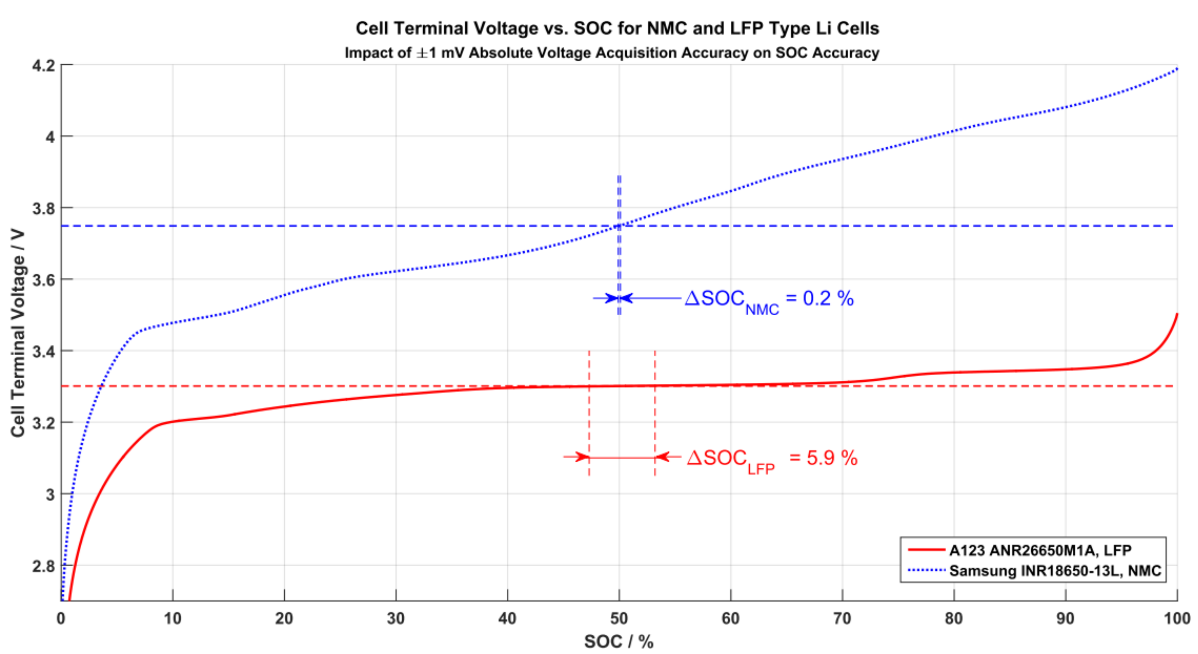
The data conversion rate that has to be considered for voltage acquisition varies widely depending on the application. Rates up to several Kilohertz are possible; however, they are rarely used because battery time constants are rather large in many use cases. High data acquisition rates are advisable, if oversampling is chosen to have a positive effect on the system behaviour. In addition, when large pulse currents occur in the application, faster monitoring can be necessary. Usually, commonly available BMS front-end chips have an absolute accuracy of 1 mV and a full range scale of 12 to 16 bits, which leads to a resolution of about 380 µV, (14 Bit resolution for BQ76PL536A, [9]). This can be critical if estimation algorithms are used on battery chemistries that have a very small voltage response regarding SOC, like lithium-iron-phosphate based cells. Figure 1 shows two plots that each represent a different type of lithium chemistry: Lithium Nickel Manganese Cobalt Oxide (NMC)- and Lithium Iron Phosphate (LFP)-type. The graph shows the Cell Terminal Voltage (CTV) over each cell type’s SOC. Any hysteresis effects are neglected for this example. The effect of a BMS’s limited voltage accuracy and its impact on SOC accuracy is the focus: for both chemistries, the CTV value at the 50% SOC point is taken as an example for the acquisition voltage (the absolute voltage value is of no relevance here). Horizontal lines for the ±1 mV inaccuracy are each added around the CTV(50% SOC) point. The intersections of the voltage inaccuracy lines with the actual CTV curve then result in vertical lines that represent the according SOC inaccuracy. As can be seen, if a ±1 mV voltage accuracy system is used to calculate the SOC on NMC type lithium cells, then a base error of 0.2% can be expected. If the same acquisition mimic is used to acquire an LFP cell’s SOC, then a base error of 5.9% has to be expected. This simple example shows the large impact of voltage acquisition accuracy on SOC estimation for various cells: the steeper the CTV-vs.-SOC curve is, the less impact a given voltage inaccuracy has. This leads to two conclusions:
- The better the voltage accuracy, the better the SOC estimation.
- Using only voltage data to determine a cell’s SOC might not be sufficient.
A better accuracy can always be achieved at the expense of higher costs. As mentioned before, typical BMS Analog Frontends (AFEs) have voltage accuracies of about ±1 mV. The details on voltage data acquisition are laid out in the paragraph Voltage Measurement on page 14.
2.3. Current Acquisition
In the previous paragraph, the impact of voltage accuracy on SOC determination was discussed. While Open Circuit Voltage (OCV) measurements for SOC determination are of highest precision during stand-still periods, for dynamic SOC determination during operation, an additional method to determine an SOC uses the measured current value: coulomb counting. This method simply integrates the current flowing into or out of a battery. After having calibrated the system to a defined state, say SOC = 100% after a full state detection, a coulomb counter could be used to track the actual SOC alone. However, solely relying on coulomb counting for precise SOC determination appears risky because current sensors are also non-ideal systems that underlie a certain drift-, offset- and temperature-error (see e.g., [10]). In addition, often the used current sensors have to meet oppositional requirements at the same time: it is not rare that current sensors in automotive applications should be able to measure currents starting in milliampere range, while also being able to measure currents up to 1000 Ampere. Depending on the application, the sensor might need to have a high bandwidth to capture fast current changes. Furthermore, the precision of the current sensor and the immunity against EMI noise should be considered [11]. As a result of all these aspects, the determined SOC will be different from the actual SOC—especially, when the battery is used in a low current regime, when noise and small offsets are playing a major role in current acquisition. To overcome the resulting problems for SOC estimation, there are approaches using algorithms and parametrised models to combine the available data and retrieve usable values [12], which however is beyond the scope of this work.
The implementation details on current data acquisition are handled in the paragraph Current Measurement on page 13 later on.
2.4. Communication
The BMS usually has to communicate to the complete system (e.g., power electronics, energy management or Vehicle Control Unit (VCU) in a vehicle), in order to provide status information and receive instructions and parameters. For this, it has to be considered which means of communication are provided or required by the system. In addition, the required communication speed, robustness and reliability need to be checked. Does the data have to be sent at a certain minimum speed to comply with safety relevant tasks or can there be a hierarchy based communication that is slow enough to save power, but still ensures the application’s timing needs? Decisions regarding these aspects may very well already have been taken on the system level, requiring the BMS to adapt to this. One example would be the need to provide a Controller Area Network (CAN) interface to talk to the system, which inherently sets some boundary conditions regarding speed, robustness and reliability.
Apart from the system level, between the BMS components, communication is also necessary. For modular systems that are spread over several Printed Circuit Boards (PCBs), e.g., it needs to be defined, if there is a ”Master” module, how it talks to ”Slave” modules that amongst others are responsible for data acquisition or control of actors. For this, basically the same aspects as for the system wide communication are relevant. Examples can be found in Section 3.3 and implementation considerations regarding communication aspects in Section 4.4.
2.5. Electromagnetic Interference
EMI can be a problem, if it is not given appropriate care. In general, all sensors are vulnerable to EMI. As a worst case, sensor acquisition could be distorted only slightly so that the BMS master is unable to identify false measurements. The other extreme condition would also result in complete uselessness of data points; however, at least it would be detectable. To reduce the influence, electric machines, power electronic components and other loads have to be designed well regarding EMI. This results in advisable application of appropriate EMI filtering devices, such as common mode chokes and blocking capacitors. These filter devices should be installed as close to the measurement paths of the sensors as possible to catch system disturbances that are e.g., defined in ISO7637-1, [13].
2.6. Contactors
Most battery packs have the requirement to be able to galvanically disconnect at least one of two battery poles. To fulfill this requirement, the battery pack needs contactors that are large enough to carry the main current, as well as being able to cut off large DC currents in the event of a hazardous fault. Since DC—unlike Alternating Current (AC)—has no repetitive zero-current events, disconnecting and extinguishing the electric arc on the contactors’ blades needs special care in the case of DC. Therefore, contactors have magnetic arc extinguishers [14], which push the arc away from the contact blades. This results in a preferred current flow direction when using these devices. This is important for the developer of a battery system to obey, otherwise the switch off performance can be reduced by a large amount [15]. Contact welding is very dangerous for a battery pack because then the pack cannot be disconnected entirely from the application. Contact welding happens when the blades are hot and are pushed against each other heavily—this scenario must be avoided at all times. When switching a contactor off under full loads, there will be an electric arc, but the contact blades will not touch in the heated and off position. Another, more hazardous scenario poses the switch-on action while there resides a potential across the not yet closed contact blades (resulting from not yet charged DC-link capacitors). If the blades are closed, they will bounce (like all mechanical switches do), and, on every bounce, an electric arc will be drawn, heating up the blades more and more. When the bouncing ends, the blades will finally close and the very hot blades are pushed towards each other, and they will weld eventually, especially at the very high current densities that occur while the contact blades are not yet fully in contact. To avoid this from happening, a special circuit has to ensure zero potential across the contactors: zero switching power has to be ensured during any switching action, and a pre-charge unit is obligatory. The pre-charge unit consists of another contactor in series with a resistor. This device is connected across the main contactor and will be activated first, to slowly increase the DC link voltage to a level equal to the pack voltage so that afterwards the main contactor can be switched on powerless [16].
2.7. Redundancy
Redundancy, besides self-tests, signal monitoring, supply monitoring and watchdog timers, is a topic that increases reliability of a system according to the ISO 26262 standard [17]. Not all systems can be designed allowing a high grade of redundancy due to cost, limited time of design process or other limitations. However, cell voltages usually are observed redundantly to a certain level, as mentioned in paragraph “voltage acquisition”. This means there are at least two separate information sources. Usually, there is a main chip that can measure the cell voltages very accurately. In addition to this chip, there is a companion chip installed that also acquires cell voltages, but only gives binary information on whether even one cell is drifting outside the predefined voltage window. This means the BMS master has to select the most trustworthy signal source—a high resolution value that is sophisticated hence more prone to fail—or a simple technology window comparator signal.
In addition, in terms of higher level processing redundancy concepts existing, where e.g., in special CPUs, protection mechanisms like lockstep, memory error correction and self test mechanisms implemented in hardware are provided [18]. In the report [19], which covers a topic similar to this paper, a broader overview on functional safety aspects is given.
2.8. Galvanic Isolation
Usually, battery packs are divided into a high voltage and a low voltage part. Those two need to be galvanically isolated, which means digital signals need to be decoupled by either optical, inductive or capacitive means. All thermal sensors need to be galvanically separated, in order to avoid high voltage faults to be allowed in the battery pack’s low voltage sections. The reason is to block high energy surges to be forwarded into the low voltage system that is usually connected to the rest of the system e.g., for communication and defined as safe to touch by the user or maintenance personnel, which is comparable to the concept of power distributing IT-net layouts.
2.9. Balancing
Several causes that lead to charge imbalance between serially connected battery cells can exist in a given system. Usually, a generic requirement would be to keep these low enough to not affect the system’s performance and reliability. Depending on the individual application, however, there might be special aspects that have to be taken care of, e.g., resulting from weight constraints (see, e.g., Section 3), or required charging currents that lead to balancing currents. Section 5 provides further information on the need to implement balancing and usual realization methods.
2.10. Other Requirements
Further requirements that are not specific for a BMS may arise from the application and also have to be kept in mind. For example, usually certain constraints regarding the available space and the system costs need to be considered. In addition, mechanical robustness of the hardware can be an important point, and, at least for aerospace related systems, weight and power consumption will be relevant as well. These and other, unmentioned aspects are for sure not irrelevant but not the main focus of this paper, and thus not examined in detail here.
3. Topologies of BMS
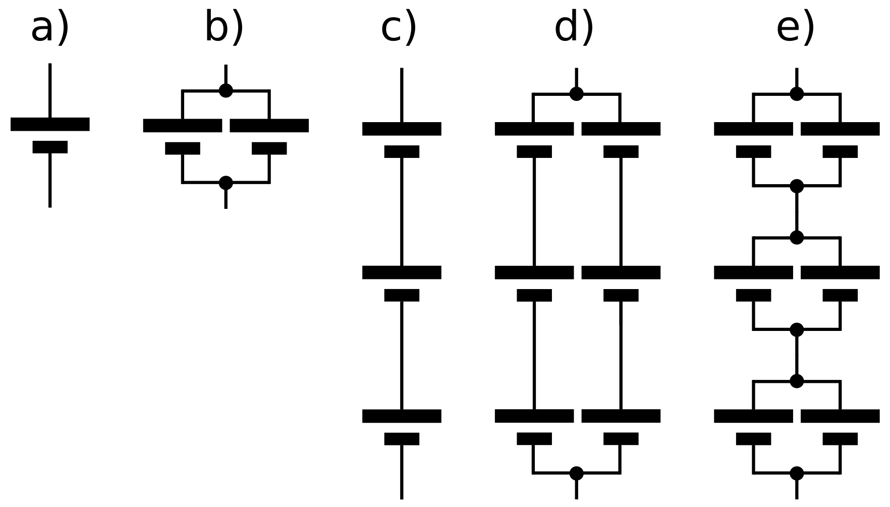
The following section shall present an overview of possible battery system structures and the resulting implications for the BMS. In order to achieve the electrical specifications (e.g., stored amount of energy, power, voltage range, maximum current) necessary for an individual system, in many cases, multiple battery cells have to be combined to form a battery pack. In principle, different connection topologies are possible for these kinds of batteries. A schematic representation is shown in Figure 2 and Table 1.
To realize a specific voltage range on the battery pack level, which reduces the current that is drawn for a given power value, cells have to be connected in series (Figure 2c), while parallel connections increase the capacity (Figure 2b). In today’s systems, one possible variant is to use multiple cells with small capacity in parallel to form modules with higher overall capacity, which are then connected in series to increase the voltage (Figure 2e), also see example Tesla Model S below). Another variant is the usage of battery cells with a high capacity, which are connected in series (Figure 2c), also see examples Mitsubishi i-MiEV, or smart fortwo ed below). Both variants are the most reasonable ones in terms of BMS complexity. A parallel connection of multiple strings of battery cells (e.g., for special redundancy requirements) would increase the expenditure for cell voltage monitoring, balancing, etc., by a factor of the number of parallel strings, while this way only one voltage measurement channel per parallel connection of n cells is needed.
Example: m cells in series are needed to reach the specified voltage, as well as n cells in parallel to provide the necessary capacity.
Case 1: Using a series connection of m times n parallel cells, m voltage channels would be needed. (see Figure 2e)
Case 2: Using a parallel connection of n strings of m cells in series, voltage measurement channels would be needed. (see Figure 2d)
In some special cases, where size, weight and power consumption are very critical, battery modules are even built without single cell monitoring and balancing. Examples are the European Space Agency (ESA)’s Mars Express and Rosetta probes. According to [20], there are three battery strings (composed of Sony 18650HC (Tokyo, Japan) [21]), each with individual DC/DC converters, which connect them to a main bus. Single cell monitoring for the strings is not mentioned, however. In [21], the authors claim that single cell monitoring is not necessary for the described application, given that a careful selection and testing of the cells are guaranteed. In [22], it is stated that the cells should originate from the same lot, which means an uninterrupted unchanged production run with the same raw materials. Other research, however, shows that, although the cells that were examined seemed equal at the time of selection, their ageing behaviour can differ substantially (see Section 5 and [23]). Thus, it is questionable if single cell monitoring really can be omitted, even when carefully selected cells of the same lot that seem to be totally equal at the time of manufacturing are used. Admittedly, the benefit of carrying battery monitoring electronics would be limited, as there would be no way to exchange damaged cells, once the spacecraft has been launched. Furthermore, a failure of these electronics could lead to the whole system failing. Apart from that, omitting single cell monitoring can be less critical for small systems with only a few cells in series. Especially when for a string the total voltage remains in a region, where theoretically (assuming identical voltages per cell) each cell remains way below its maximum allowed voltage and above its minimum allowed voltage, the probability of one cell becoming critical is comparatively small.
To implement the basic monitoring functionality needed for a safe operation of the batteries, several off-the-shelf Application-specific integrated circuits (ASICs) are offered by well-known semiconductor manufacturers. As there is a wide variety of available components, only representative examples, which are available or in use at the time of writing, are provided here.
For small personal electronic devices (smartphones, e-book readers, audio players, etc.) that often contain only one single battery cell, so-called “fuel gauges” ICs exist. These components represent the simplest form of a BMS ASIC. They provide functions like voltage monitoring, current measurement and temperature measurement for one cell. In addition, often some kind of SOC estimation, based on the measured values, is integrated. Some of these devices also contain further functional elements, like charging regulators.
Examples for this class of components are TI’s (Texas Instruments) (Dallas, TX, USA) “bq27220 Single-Cell CEDV Fuel Gauge” [1] or Maxim’s “Micropower 1-Cell/2-Cell Li+ ModelGauge ICs” [2]. Both are designed to be used in combination with a protection circuit that can disconnect the battery in case of failure. Both ICs measure voltage and temperature and estimate the cell’s SOC. The TI component measures the cell’s current in order to estimate the SOC via coulomb-counting, while Maxim claims in the datasheet that their IC uses an “advanced battery model” to estimate the SOC without needing a current measurement resistor. The measured and calculated values are provided to the surrounding system via serial interfaces in both cases.
In the Appendix A and the Supplementary Materials section, a list of all BMS ICs that were mentioned in the text and some similar types can be found (Table A1).
3.1. Modularization
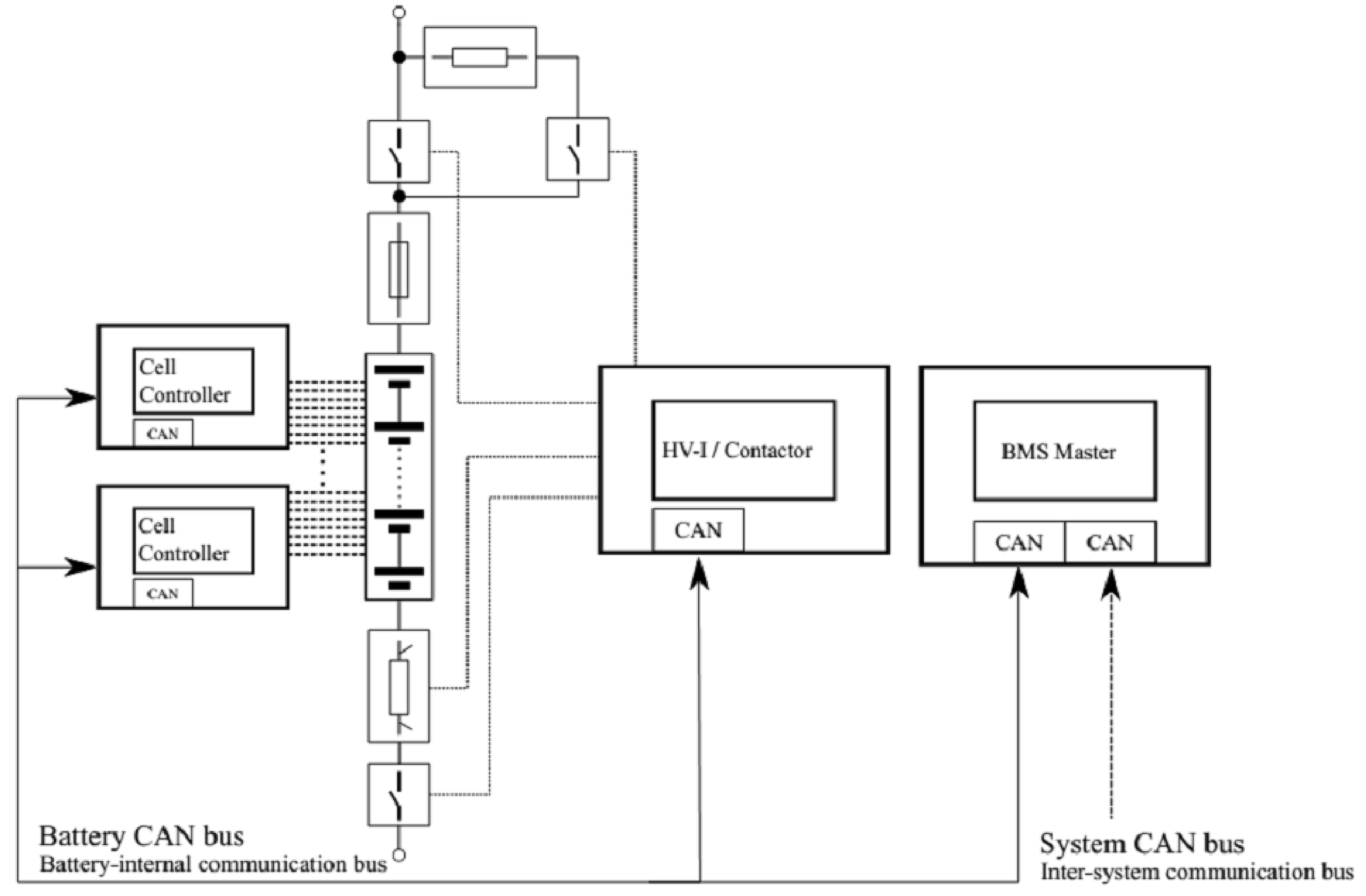
For applications in need of higher power and/or with greater energy demand, the battery pack has to consist of several cells. ICs are offered for these kinds of systems that provide monitoring for several cells at once and also provide means for balancing, which is not needed in one-cell-systems. In these kinds of systems, usually more advanced functions are implemented in one central module or Electronic Control Unit (ECU), sometimes known as “BMS-Master”. Figure 3 shows the structure of a typical system of this class. As examples for tasks the master cares about, sophisticated SOC estimation, or power prediction algorithms, which need a certain amount of processing power, can be named. An overview can be found in [12].
The modules carrying the front-end ICs are then often referred to as “BMS-Slaves”. They are used for basic functions like signal acquisition, filtering, etc., which are carried out by the monitoring ICs named above. (see e.g., [24] or the examples in Section 3.3). As examples, Texas Instruments’ bq76PL536A [9] (used in Tesla Model-S (Palo Alto, CA, USA) and possibly in smart fortwo ed, see Section 3.3), Linear Technology’s (Milpitas, CA, USA) LT6802G-2 [25] (used in Mitsubishi Motors i-MiEV (Tokyo, Japan)), Maxim Integrated’s (San Jose, CA, USA) MAX11068 [3] (used in VW e-Up), or AMS’ (Premstätten, Austria) AS8506C [26] can be named. The TI bq76PL536A, MAX11068 and LT6802G-2 provide passive balancing, while the AMS device can be used for passive balancing topologies, but also provides active balancing capabilities using an external transformer. More on balancing can be found in Section 5. At the time of writing, there are already successors available for most of the named ICs, e.g., TI bq76PL455 [27] or LTC6811 [28]—also see Section 4.2. As mentioned in the section on requirements, a certain level of redundancy regarding voltage monitoring is usually desired. Thus, so-called secondary protection ICs often can be used in combination with the described ICs (or are even contained in the same package) to provide an additional level of safety. Another possibility would be the usage of a completely redundant BMS, which, however, would largely increase the costs.
3.2. Communication and Data Transfer
Usually, the front-end ICs can be daisy-chained to use them in a larger cell stack. The MAX11068, e.g., features two I2C ports to connect to the next chip lower in the stack and the next one, which is higher in the stack [3]. Like the MAX11068, the TI bq76PL536A also provides level-shifted interfaces to connect to ICs higher and lower in the stack. Furthermore it provides a dedicated host-interface, to connect to a microcontroller, while, when using the MAX11068, this is done using the lowest I2C port in the stack [3,9]. The LT6802G-2 can be connected to using the Serial Peripheral Interface (SPI) bus. The chip’s interface does not allow daisy-chaining multiple chips directly, but connecting multiple chips to the same SPI bus using additional digital isolators [25] is possible.
In many cases, the daisy-chain connections are used to connect multiple ICs on one PCB to each other. To implement the connection to the rest of the system and control the BMS ASIC’s functions, usually a low-cost microcontroller is used (see examples i-MiEV and smart fortwo ed below). For the connection to further modules on other PCBs and to connect to the BMS master, often a field bus like CAN is used to provide a more robust communication. The same goes for the connection between the master and the rest of the system (also see Section 4.4).
3.3. Real-World Examples
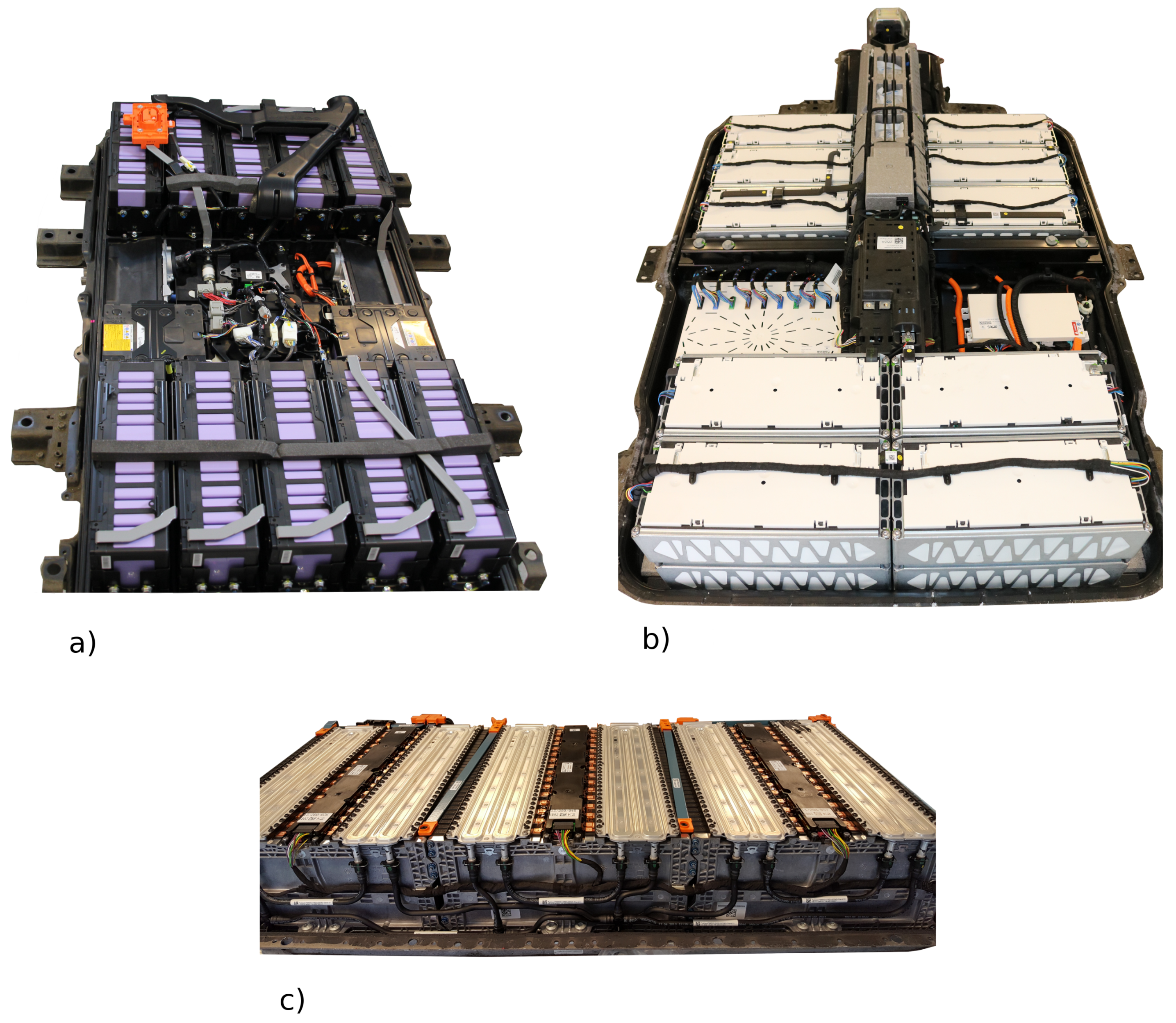
As part of a research project conducted at the authors’ institute, the traction batteries of several commercially available electric vehicles have been disassembled, in order to analyse the cell ageing after a certain time of usage. As a side-product, the authors of this work were able to analyse and compare the different systems, while the disassembly was done. Thus, in the following, four real-world examples can be provided. (The data provided regarding the Tesla Model-S battery are based on a presentation by AVL [29] and our own analysis of a single module, purchased separately. The other batteries were available and disassembled completely.).
Example (1) Mitsubishi i-MiEV
The first example is the traction battery of a Mitsubishi i-MiEV (initial registration: February 2014), shown in Figure 4a. It contains 10 Modules of eight cells and two modules with four cells, which leads to a total amount of 88 prismatic cells, all connected serially using screwed contacts. On top of each of the modules, a PCB is mounted, which—among other things—contains an LTC6802G-2. This IC is designed to monitor up to 12 lithium-ion cells, which are connected in series. The same PCB design is used for the module versions with four and eight cells. When used with four cells, the PCB is not fully populated, as four of eight available channels are not needed. The eight-cell modules use a second PCB to connect the second half of the module to the four remaining channels. The PCB on top of the modules is called the Cell Management Unit (CMU) in the official service manual for the car [30]. In addition to voltage measurement, each PCB contains three temperature sensors, which are connected to a controller located next to the Linear Technology BMS IC.
Apart from the cell modules, the battery housing contains contactors (separate ones for the connection to the inverter and for DC charging), fuses, a service plug, an LEM (Freiburg im Üechtland, Switzerland) current transducer, an insulation monitor and a fan to extract cooling air. The service plug splits up the pack into two sections when it is removed. In the car, it can be found below the left hand seat. The main fuse also splits the pack in the middle. The cooling air originates from the vehicle’s air conditioning system and is partially guided by short plastic pipes and forwarded to the outside by the mentioned fan.
Not contained in the battery housing is the BMS master, or Battery Management Unit (BMU) [30], which communicates to the rest of the vehicle. It is located below the rear bench seat of the vehicle. The contactors, the current transducer and the insulation monitor are connected directly to the BMU. The CMUs on top of the cell modules are connected to each other and to the BMU via an internal CAN bus. Some of the signals on the battery internal CAN bus can also be found on the car’s main CAN bus in lower resolution. Compared to the smart’s battery, which is described below, there is a lot of free space in the iMiEV’s battery housing, which may be a side effect of the air cooling.
Unfortunately, for the remaining vehicles/batteries, no documentation from the manufacturers was available, thus the information provided on the other systems is less detailed than for the i-MiEV.
Example (2) Smart Fortwo Electric Drive (Dt. Accumotive)
The second example is a battery pack taken from a smart fortwo electric drive (third generation, initial registration: September 2014), built by Deutsche Accumotive, which is shown in Figure 4c). It consists of 90 pouchbag cells, connected in series by welded connections. The cells are mounted in plastic frames, organized in three rows positioned side by side with cooling plates for a liquid cooling system mounted on top.
The basic monitoring tasks are performed by ICs of TI with anonymized product code. A comparison of the PCB found in the battery pack and the specifications of bq76PL536A, however, showed that the used product is at least very similar to bq76PL536A, which is also built into the Tesla Model-S battery that was available for analysis (see below). Each of the three PCBs contains six monitoring ICs and one microcontroller with a galvanically isolated connection to the rest of the system (most likely CAN). TI’s bq76PL536A can be daisy-chained in order to need only one communication connection to the system, which can also be observed here. For cell voltage measurement, there are connections of flexible PCB between the cells’ terminals and the BMS PCBs located between the terminals. In addition, several temperature sensors can be observed. A module that seems to be the BMS master (Bosch) can be found next to the pack’s communication signal connector. The main contactors and a fuse are placed next to the power connector.
This battery showed the highest integration efforts of all specimens examined in this work’s context. The whole BMS is located in the battery’s case, it is built very space efficient and uses few cables. Altogether, it appears to be designed holistically, having the complete system in mind, as opposed to the next example.
Example (3) VW e-Up
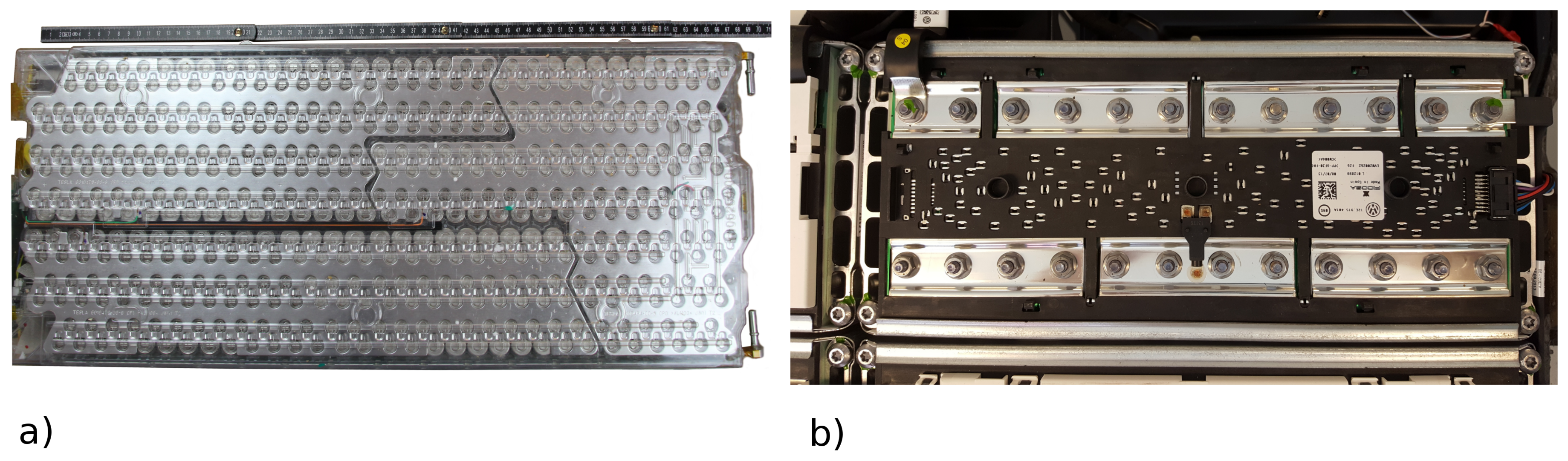
Another battery pack that has been disassembled originates from the Volkswagen e-Up (2013, initial registration: February 2014). It is shown in Figure 4b. The pack contains 17 serially connected modules (Figure 5b), each consisting of six serially connected pairs of two prismatic cells.
The e-Up battery does not have a cooling system or a service disconnect, dividing the battery into two halves. The BMS modules are centralized, and the white box on the left side of Figure 4b) contains the measurement ICs (or BMS slave) for the whole battery pack. To the right of it, below a black cover, the contactors, fuse and current measurement can be found. The other white box contains some kind of BMS master. A large amount of voltage measurement wires connects the individual cells to the slave module, where Maxim’s MAX11068 [3] is used for the measurement and balancing tasks with MAX11081 [8] as a secondary protection device. A closer look at the PCB shows that nine MAX11068 (12 voltage measurement channels each) are daisy-chained via I2C, which is also used to connect the last IC to the rest of the system. There is no microcontroller converting to a more robust field bus, like e.g., CAN. Apart from that, the slave’s PCB is filled with a large amount of balancing resistors taking up most of the space.
Example (4) Tesla Model-S
An exception among the named examples is the Tesla Model-S battery. Here, only one module was available for analysis (see Figure 5a). According to [29], the whole battery consists of 7104 single 18,650 cells, divided into 16 modules in a 96s74p configuration, which means that each module contains a series connection of 6 × 74 parallel cells. The individual cells are connected via bond-wires, which also act as fuses. The nominal voltage is 355 V and a liquid cooling system exists. For the BMS’ cell-monitoring functions, TI’s bq76PL536A-Q1 is used, which is placed on a PCB mounted to one side of the module. The cell voltage measurement is performed using wires welded to the connecting plates of the parallel connections.
Comparing the different battery packs shown here, it can be determined that there are significant differences in the construction, especially regarding the level of integration observed. While the smart ed pack features large scale integration, the batteries of VW e-Up and Mitsubishi i-MiEV show only very moderate integration efforts. The former pack contains comparatively little cabling. The cell monitoring ICs are mounted on oblong PCBs on top of the battery modules in a very space saving manner, while the BMS-master is also located inside the pack, next to the signal connector to the car. In the i-MiEV battery, the cell monitoring ICs are also mounted on PCBs on top of the battery modules, taking a bit more space. The BMS-master that also controls the contactors is not contained in the pack’s housing, which is why a certain amount of cabling is necessary to connect the components to each other. A part of the cables found in the i-MiEV battery could be reduced by putting the BMS-master into the pack and by organizing the power supply cabling more reasonably. The e-Up pack finally is an example for a central monitoring unit. Every cell voltage is acquired using long voltage measurement cables, which connect cell modules to the monitoring unit in a star layout.
Apart from these differences, the BMS components are very similar in terms of their functionality. All mentioned examples use specialized monitoring ICs to implement the basic functions, which are supervised by a central ECU (BMS-master) for higher functions, or central functions like contactor control.
4. Measurement
This section will give an overview of the field of measurement technology for HV battery systems. The measurement technology is a key component of a battery management system and enables the determination of state variables such as the SOC, State of Health (SOH) or State of Function (SOF). Measured variables usually include cell voltages, the total voltage of the battery system, the total current and the temperature. By knowing the state variables, the battery system can be protected for example against overcharging or deep discharging. In addition to providing safety related functions, the state variables allow for an optimized utilization of the battery system.
If the application of the battery storage is known, necessary requirements on the sensors can be derived. Typical requirements to be considered can be costs, bandwidth, precision, measurement range or size. A detailed overview of the requirements was given in Section 2.
4.1. Current Measurement
The current measurement is of great importance, especially for the determination of the state variables of the battery system. As shown in Figure 1, depending on the battery type, the cell voltage only shows a low dependence on the SOC. A precise measurement of the total current allows for determining the SOC by integrating the current. In the following, established methods of current sensing are presented and compared to each other.
Current acquisition devices can be divided into two basic sensor technologies: galvanically connected and isolated. The widely used method of shunt resistor current sensing belongs to the galvanically connected technologies. An example for the isolated current acquisition utilizes the electromagnetic properties of the current to acquire the magnetic field strength using hall sensors. Besides the sensor technology, the position in the battery pack has to be considered as well. If the battery system consists of several switchable strings, it can be important to not only implement one main current monitoring device, but one device for each battery string. This is important to trace power misbalancing during operation.
4.1.1. Shunt Resistor
In this measurement method, a low-resistance high-precision resistor in combination with a high precision voltage measurement system is used to determine the current. The resistor is located in the current conducting path so that a voltage drop proportional to the current can be measured. Due to the current flowing through the shunt, a power loss is caused , which leads to a temperature rise of the shunt resistor. The need to keep the losses as small as possible conflicts with the necessity to select the value of the resistor to be high enough to generate a suitable voltage drop for the measuring system [11]. Furthermore, the thermal drift is an important characteristic of a shunt resistor. If very high measurement accuracy is required, the precision resistor should have a small temperature coefficient and a high long-term stability.
The method (shunt) can be used to measure direct currents and alternating currents. Further advantages are simplicity and linearity of the measurement system as well as the possibility to achieve high bandwidths. The measurement range is limited by the accuracy of the voltage measurement [10,31].
Low-Side vs. High-Side Measuring
When using the shunt resistor method for measuring current, it is crucial to choose the right placement for the resistor in the current path. If the shunt resistor is located between the positive pole of the battery and the load, one speaks of high-side measuring. When the resistor is placed between the load and ground or the negative pole of the battery, we are talking about low-side measuring.
The main advantage of the low-side measuring is the low input common mode voltage so that a large number of current sense amplifiers can be used. In addition, only low supply voltages are required for the amplifier circuits and the system can be built in a very simple and low-cost way. Disadvantageous in this arrangement is the disturbance of the ground path that leads to lifting the load from the system ground to a higher level due to the resistance of the shunt. Furthermore, high load current bypassing the low-side monitor—for instance caused by accidental short-circuit—cannot be detected [10].
In contrast, high-side measuring allows connecting loads to the ground without additional disturbances in the path. Moreover, short-circuits, as mentioned above, can be detected. The need of level shifting the output of the amplifier down to system operating voltage levels is the essential disadvantage of this method. Compared to low-side measuring, the high-side current sense amplifier must be able to withstand high common mode voltages.
4.1.2. Contactless Current Sensors
Apart from current measurement using shunt resistors, which are directly integrated in the current path, also contactless current sensors are commercially available. These sensors use the magnetic field that a current produces and are e.g., known as magneto resistive sensors (e.g., Sensitec (Lahnau, Germany) CDS4150 [32]), fluxgate sensors (e.g., LEM CAB300 [33]), or Hall sensors, which will be examined in a little more detail in the following. As the name suggests, Hall sensors are based on the Hall effect and are able to sense DC and AC. If a current flows through the Hall sensor, the sensor generates a voltage that is proportional to the product of magnetic flux density and current [31,34]. In contrast to the shunt-based method, the Hall sensor does not add any further resistance to the current path, which means that no additional conductive losses occur. In addition, the galvanic isolation this method provides is advantageous. No further optocouplers or digital insulators are required for signal conditioning when Hall sensors are used.
Hall sensors can be bought as integrated circuits and need to be placed on the current path (such as Honeywell’s (Morris Plains, NJ, USA) SS413A [35]). The current sensors that measure the field strength usually have an analog voltage or current output that needs filtering. In addition, complete modules that can be built into the application without signal treatment circuitry are available. These sensor blocks usually consist of a ferrite ring with an inserted Hall sensor. A busbar or current link is then put through this ring for the ferrite to catch most of the busbar’s field. Galvanic isolation is given at all times here (see LEM’s product family HAH1BV as an example [36]).
One of the main disadvantages of the Hall effect based sensors is their limited bandwidth—usually not higher than a few ten kHz, such as Allegro Microsystems’ A136x product family (Worcester, MA, USA) [37] (120 kHz) or LEM’s LTC200 series sensors (100 kHz) [38]. If the battery system developer needs an increased bandwidth, then the classic shunt resistor must be used, which in general is also considered less pricey, as higher costs and larger volume are associated with Hall sensors. A further drawback of this measuring method is that the output signal of a Hall effect sensor has a large temperature drift [10] that needs to be compensated in the sensor module or the signal processing chain.
4.2. Voltage Measurement
In battery packs assembled from lithium-ion cells, typically each cell voltage as well as the overall pack voltage is measured. While the cell voltages are just a few volts, the pack voltage can reach voltages of more than 800 V [39,40]. Therefore, it has to be distinguished between cell voltage measurement and pack voltage measurement. The fact that the sum of the individual cell voltages must be identical to the total pack voltage can be used as a plausibility criterion [41].
4.2.1. Cell Voltage Measurement
As mentioned in Section 2.2 and Section 3, the acquisition of cell voltages is usually done by integrated BMS Frontend chips. The chips that are on the market at the time this is written allow connection of cell counts of three up to 16 (e.g., TI’s BQ76PL536A [9], BQ76PL455A [27], Linear Technology’s LT680x series [42], Intersil’s (Milpitas, CA, USA) ISL78600 [43], and Maxim-IC’s MAX17843 [44]). Secondary supervisory ICs such as LT6801 by Linear Technologies [45] or Maxim-IC’s MAX17880 [46] can improve redundancy and therefore system reliability by a large amount.
4.2.2. Pack Voltage Measurement
The pack voltage acquisition is done by a separate measurement unit, typically consisting of a voltage divider, an impedance converter, a filter and an Analog Digital Converter (ADC). The voltage divider is necessary for scaling down the pack voltage to an adequate measuring voltage, which is in the range of the ADC. Depending on the pack voltage and on the electric strength of the resistors, it may be necessary to use several resistors for a safe voltage divider. In addition, a Zener diode should be placed in parallel to the measuring resistor for protecting the following measurement circuits against overvoltage. Since the voltage divider is designed to be highly resistive in order to keep the losses low, the voltage tap of the measuring resistor should be very high-resistance in order not to load the voltage divider. For this reason, an impedance converter that is followed by the filter circuit and the ADC should be used to tap the voltage.
4.3. Temperature Measurement
Common temperature sensors for the measurement of temperatures in the region that is relevant for battery management applications are of Negative Temperature Coefficient (NTC) (metal oxide) or Positive Temperature Coefficient (PTC) (semiconductor) type. These sensors change their resistance as a function of the temperature—for NTC, the resistance decreases with increasing temperature, for PTC vice versa. The measurement is realized by capturing the voltage drop while a constant current is flowing through the resistor. They are typically usable in regions of −50 °C to 150 °C, relatively cheap, easily applicable and are linear in a certain range, but behave nonlinearly in adjacent temperature ranges (e.g., very low and very high temperatures) [47], Chapter 19.1. Usually, BMS front end ICs provide one or more ADC channels for temperature measurement (see Section 3.3, [3,9,25,27,28,42,43,45,48,49,50]), the usage of NTC type thermistors is common (see e.g., [1,42]). From the nonlinearity, it follows that, in the digital processing chain (e.g., the intelligent cell controller board), a look up table has to be implemented to allow the calculation of correct temperatures from measured voltages. Other sensors that use a digital interface and provide a readily calculated temperature value are more conveniently usable. An example for a sensor with a built in digital interface (“1-Wire”) is the DS18B20 (Maxim Integrated) [51]. Similar sensors using I2C communication can be found at Texas Instruments (TMP100 [52]), LM75 [53], etc.). These sensors can be easily connected to a microcontroller environment. However, it has to be noted that, even though digital sensors are usually known for their robustness, care has to be taken when positioning these sensors close to the high-power path in a battery pack to reduce EMI induced failures.
Other ways of temperature measurement, e.g., using metal based PTCs, as the well-known PT100, or making use of the thermoelectric effect (Thermocouple) could provide higher accuracies and a wider temperature range; however, this would involve a higher complexity in terms of electronics [47], Chapter 19.1.
4.4. Data Transfer
As already mentioned, communication between individual BMS-modules, as well as between BMS and the overall system, is required. Nowadays, the CAN bus is one of the most prominent buses used in vehicle environments because it is very flexible regarding the number of bus members, as well as offering a good noise resistance. The simpler Local Interconnect Network (LIN)-bus, which is also widely used e.g., has the disadvantages that it is slower, less flexible and non-differential, but, on the contrary, also is less expensive due to reduced hardware efforts [54]. Other buses that are mostly used on short distances, such as chip to chip communication (see above), is the SPI interface, I2C interface or the Onewire bus. Due to their non-differential signals, they are not robust against disturbances on a longer, more exposed line, such as inter-module buses. For the latter task, the previously mentioned CAN bus is a good choice. If the CAN bus at its highest speed of 1 Mbps is too slow, or the demand for real-time deterministic capability exists, then the FlexRay bus seems adequate. An Ethernet connection is also sometimes used to connect the battery system with the application, especially when high communication speed and large data volumes required.
5. Balancing
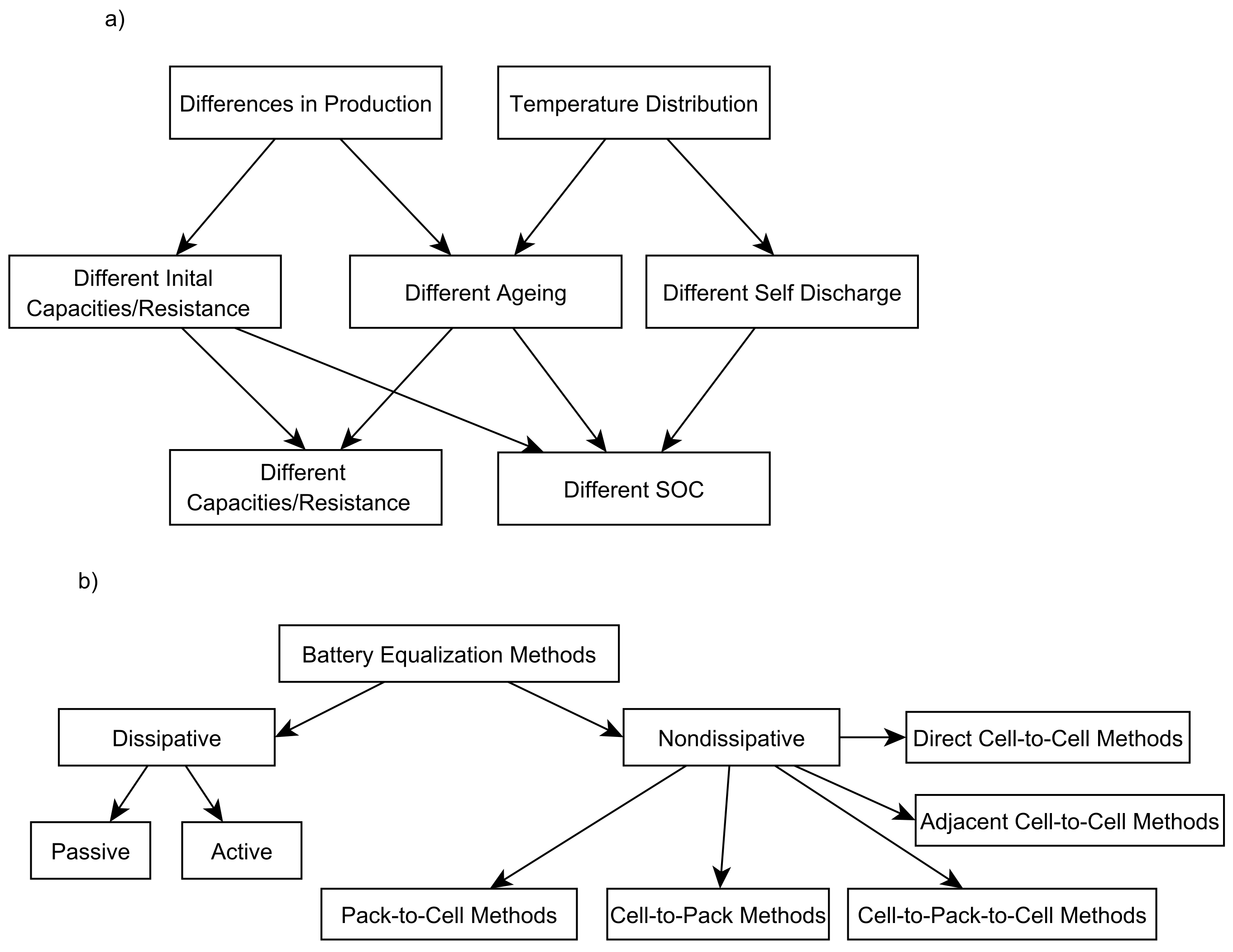
Due to several reasons, at a given time SOC, values can differ in a serial connection of cells. Figure 6a shows the causes that can lead to inhomogeneities between the single cells in a battery pack. The cause for the inhomogeneities are production related differences on the one hand and different operational and environmental conditions, e.g., temperature, on the other hand. These causes can lead to different initial conditions, different ageing and different self discharge rates, which then result in deviating SOC, capacity and resistance values [55]. The inhomogeneities regarding the inner resistance of the cells are not covered in this section, but rather the differences of the SOC and capacity. Ref. [23] has reviewed the changes of different cells’ capacities in a batch of 18,650 consumer cells with the same initial capacity and that were stressed with the same load profile. Even though all cells were selected to have the same initial capacity, the capacity deviates after some cycles. If a remaining capacity of 80% is chosen as an end of life criterion, the tested 18,650 cells showed a cycle life between about 1000 and 1500 cycles. This spread shows that, at least for some batteries, the selection of equal battery cells at the beginning of life is not sufficient to guarantee a permanently equal capacity after usage. In fact, the capacity of each cell should rather be monitored and, if necessary, handled. Even though the evolution of the self discharge rate of the cells was not in the scope of this work, one can assume that there is also variation in this parameter. Ref. [56] has analysed the self-discharge behaviour of commercial pouch cells by Kokam. An equivalent self-discharge resistance was introduced and four cells were stored at 40 °C. Even though cell type and storage conditions were the same, the cell self-discharge resistance varied between 10 kΩ and 14 kΩ, which is an increase of 40% from the weakest to the strongest cell. Additionally, the Arrhenius like temperature dependency from 20 °C onwards is shown. Since there are always temperature inhomogeneities in battery packs, also a deviating self discharge rate for different battery cells in one pack can be observed due to this effect.
The difference in SOC, as well as the differences in capacity and internal resistance, can cause the available energy of a battery pack to decrease and can be addressed with balancing circuitry. Literature describes numerous hardware implementations for electronics that are capable of equalizing the voltage of several connected batteries. An overview of the possible topologies is given in [55,58]. Figure 6b shows the possible variants. Other sources categorize different balancing methods by the control methods (e.g., active/passive) or by commercial availability. Especially when it comes to active balancing methods, a wide range of solutions is offered by literature. Nevertheless, most commercially available battery packs use controlled passive balancing systems (see, e.g., the systems shown in Chapter 3.3). These systems consist of a balancing resistor that can be switched in parallel to a battery cell for each battery cell or parallel connection of battery cells. The main advantage of this approach is its simplicity compared to more complex active and non dissipative solutions. Since the cells can only be discharged with this balancing topology, only SOC changes can be addressed.
Reverse engineering of the aforementioned battery packs showed that these systems are using small balancing currents in the range of 100 mA (Balancing resistances in the range of 30 Ω to 40 Ω were observed, which leads to the described balancing current if a cell voltage of 4.2 V is assumed.). This balancing current does not vary with the capacity of the cells used in the battery packs and therefore seems to be limited by the energy dissipation of the battery management system or the diameter of the cabling between cell and battery surveillance circuitry. All observed systems (as shown in Chapter 3.3) are dissipating a power between 387 mW and 430 mW per cell, assuming a cell voltage of 4.2 V. A higher current during balancing would require larger, more expensive (in terms of component cost and PCB area) balancing resistors or higher temperatures, which would lead to higher component stress. In order to address different capacities, more complex approaches utilising power electronics to redistribute energy between the cells of a battery pack are required. This way, energy of high capacity cells can be used to support low capacity cells and therefore increase the available energy of a battery pack. These solutions mostly require some complex control algorithms for the power electronics as well as costly inductances (There are already battery management ICs on the market that integrate circuitry for the control of active balancing systems (e.g., [26]). These systems were still not yet observed by the authors in commercially available automotive battery packs in volume markets.).
6. Safety and Reliability
One of the main purposes of using a BMS is to minimize the risks associated with the operation of lithium-ion cells in battery packs. In the following section, some examples of typical safety functions of a BMS are given. Afterwards, design aspects related to the safety of the BMS itself are discussed. According to [59], the main hazards inside lithium-ion battery packs are exposure to high voltage, arcing, fire, vented gas combustibility and vented gas toxicity. In combination with suitable battery pack design, the safety functions of the BMS should minimize the likelihood of occurrence and severity of these events.
Insulation monitoring (further discussed in the next section) and interlock circuits can be used to ensure the high voltage safety of the battery pack. This also lowers the risk of arcing events due to buildup of pollution or condensation inside the battery pack, which also affect the insulation resistance because they can be detected at an early stage. The BMS hardware design should follow relevant standards [60,61] for proper creepage and clearance distances for the PCB as well as all connectors.
Regarding the communication interfaces with other control units or auxiliary power supply (low voltage vehicle electrical system), care has to be taken to ensure galvanic isolation from the high battery voltage. During design, it has to be assured that the selected isolation device fulfills the criteria for “reinforced isolation”, as it has to provide sufficient protection against electric shock [62]. Traditionally, optocouplers have been used for galvanic signal isolation. In recent years, so-called “Digital Isolators” ICs have entered the market and promise superior performance [63], especially in terms of reliability and ease-of-use. These ICs exhibit an internal isolation barrier and capacitive or inductively coupled signal transmission circuits.
The risk of fire can be lowered by placing temperature sensors inside the pack and reacting appropriately to critical temperature values. In addition, sensorless temperature detection methods using indirect sensing methods, like electrochemical impedance spectroscopy [64,65,66] can be used additionally. New methods to acquire temperature along wire harnesses within complex electrical systems can also be utilized to add safety [67].
As the examples above show, in many applications, contactors are used to allow disconnecting the battery pack from the system. As all contactors have a finite break current rating, a melting fuse should be used additionally. The operating characteristics of both fuse and contactors have to be taken into account to make sure that a fault current can be interrupted in all cases. Parasitic capacitance and inductance inside the battery pack, as well as from the application, have to be taken into account for the selection of the fuse rating because of their significant influence on the rise time and magnitude of the short circuit current [68].
The intrinsic safety of the cells depends on the strict compliance to the defined safe operation conditions of the cells. The BMS has to inhibit the charging of the battery outside a defined temperature window. Especially lithium plating at low temperatures is a serious risk, as it can lead to the formation of dendrites and subsequent internal short circuits of the cells [69]. In addition, no operation of the battery pack after a deep discharge should be allowed by the BMS because of the possibility of short circuits due to corrosion phenomena [70]. Some diagnostic algorithms are proposed in literature to detect internal short circuits [71,72] at early stages.
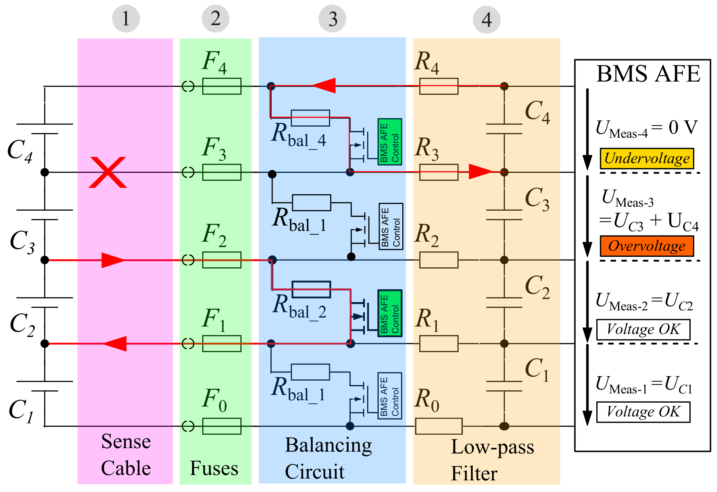
As the hardware and software implementation of the BMS get increasingly complex, the possibility of software errors and sensor faults also rises. One critical issue is the integrity of the cell voltage sense cables between the battery cells and the cell supervisory unit. A sense line cable break cannot immediately be detected by measuring the voltage alone [73]. Figure 7 illustrates the issue: due to the low-pass filter capacitances (Section 4 in Figure 7), a disconnected line (Section 1) or a blown fuse (Section 2) does not lead to an immediate voltage drop. The voltage at the measurement hardware (BMS AFE) decays rather slowly over the course of several minutes or even longer, depending on the magnitude of the quiescent current. This can be a critical safety issue, as the cell voltage of at least two neighbouring cells cannot be supervised any longer. By using the cell balancing system or current source circuits, such a fault can be detected [73,74]. This is also illustrated in Figure 7: enabling the balancing circuit (Section 3) leads to a voltage change at the adjacent cells, whose magnitude is much larger than normal and can easily be detected by the AFE. Other types of faults, for example defective sensors, can be detected by appropriate diagnostic algorithms [75]. Knowledge of the electrical behaviour of batteries can also be used to check sensor signals for validity. For example, a sudden increase of the discharge current should lead to a certain voltage drop for all battery cells in a serially connected string. An increasing or constant voltage value of individual cells is therefore not plausible and could be a sign of a sensor malfunction in that situation.
For all safety measures that are implemented, it has to be considered that the implementation of all the aforementioned (and other) safety functions can, by itself, be the cause of further hazards. Take for example the case of an opening of the main contactors by the BMS during drive operation of a battery electric vehicle: depending on the momentary driving situation, the following sudden loss of power can be more hazardous than the actual cause of the contactor opening action (for example, a short crossing of an undervoltage limit during acceleration). Similar considerations apply to aircraft or other applications, where a sudden loss of power is not tolerable. A counter-example is the case of a photovoltaic battery storage system, which does not feed power to critical systems. In this case, protection of the battery should be the higher priority. The two optimization goals of safety and reliability have to be balanced against each other for the specific applications.
6.1. Insulation Measurement
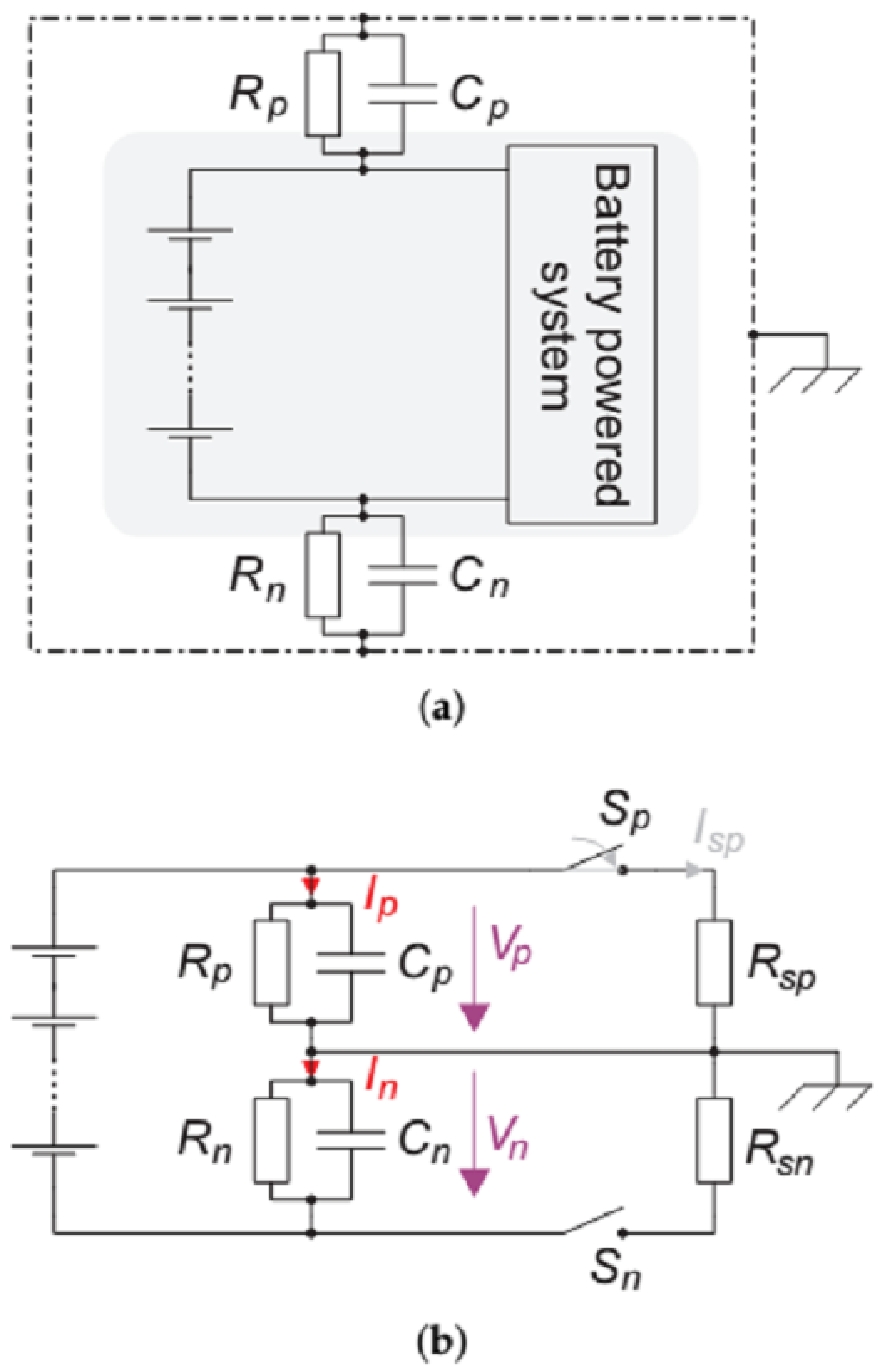
Usually, the high voltage system in electric- or part electric vehicles is constructed as IT net. This means that no deliberate connection between vehicle chassis and high voltage system is given. A single case of failure does not lead to a potentially dangerous situation. However, a second case of failure does. Thus, the first fault needs to be detected so the system can act appropriately. Figure 8a depicts a battery powered high voltage system in IT-net configuration, indicated by a grey box, which is surrounded by a chassis, symbolized by a dash dot line.
With respect to a battery pack, an electric insulation or rather an electrically insulating material is generally characterized by its electric resistance. This insulation resistance is distributed over the whole electric circuit. To describe the insulation practically, the model in Figure 8a can be used, where and are the concentrated insulation resistances between the positive and the negative pole of the high voltage system and the chassis. The same applies to the capacitances and , and these are the sum of parasitic cable capacitances and possibly placed EMC filter capacitances. Due to transient measurement methods, these capacitances should be taken in to account.
Several techniques to measure the insulation resistance are common. Yin et al. [76] measures common mode currents using a toroidal coil, which is externally excited with an alternating signal. When a common mode current flows through the coil, the excitation signal will be changed and, in combination with a voltage measurement, the insulation resistance can be calculated. However, in order for this method to work, the main current conductors have to be guided through the coil, which is a disadvantage of this system.
A more common method is described in Li et al. [77]. As shown in Figure 8b, only two additional switches and two resistors are needed to determine the insulation resistances and . In terms of the measurement of insulation resistances, the capacitances and are contributing as disturbances. The two switches are able to produce different states where the chassis’ potential is shifted with respect to the system’s potential. For example, when switch is closed, a current flows through . Because this current gets added to the current through , the voltage increases, and, as a consequence, decreases. In short, the chassis potential will be shifted with respect to the high voltage system. By measuring the different states’ voltages, the insulation resistance can be calculated. To sum up, the presented insulation measurement system only needs two switches, two concentrated resistors and two voltage measurement units.
A slightly different system is presented in [78]. The described solution uses four switches and four concentrated resistors, so it is able to create more different states. As a result, only one voltage measurement is needed. Ref. [79] presents a quite simple solution that uses only one switch. However, it is not able to detect symmetric insulation resistance errors.
As mentioned, the insulation capacitance is a kind of disturbance for the insulation resistance measurement. Whenever a change in the potential between chassis and HV system occurs, these capacitances get recharged. The insulation capacitance and the insulation resistance form an circuit with a time-constant depending on R and C. Therefore, after a new measurement state has been set, the voltage between chassis and HV system changes very slowly. The measurement unit has to wait, for instance, five time constants, until it is capable of determining the correct insulation resistance value.
Van Vugt and Bijman [80] are presenting a good comparison of three common insulation measurement devices with slightly different measurement techniques. One device each from Eaton (Dublin, Ireland), from Siemens (Berlin/München, Germany) and from Bender (Grünberg, Germany) is tested. The Eaton only applies a constant DC voltage; thus, this device is not able to measure insulation faults behind a rectifier. The second device, the Siemens, applies an altering voltage so it works in the same way as mentioned before. The last one, the Bender, measures with an altering voltage as well and in addition is capable of adapting the measuring time depending on the time constant of R and C.
The insulation measurement is also standardized in a few norms. Distinguished in Measurement Method and recommended Minimum Insulation Resistance, they will be named in the following subsections.
6.1.1. Measurement Method
In ECE-TRANS2010 [81], ISO6469-1 [82] and ECE-R100 [40], the measurement method is standardized like depicted in Figure 8b. A well-known additional resistor and a switch are used to create different states in voltage between chassis and HV system. In addition, ISO6469-1 [82] and ECE-TRANS2010 claim a minimum inner resistance of 10 MΩ of the voltage measurement unit. Nevertheless, ECE-R100 claims a minimum inner resistance of 1 MΩ. This contrasts with DIN61557-8 [83], where a minimum resistance of 30 and a minimum total resistance of 15 kΩ is claimed. Moreover, ISO6469-1 specifies the additional resistor to at least 100 to 500 with a minimum accuracy of 2%, where ECE-R100 specifies a minimum value of 500 . The measuring time to capture the insulation resistance is allowed to be at most 100 s as defined in DIN61557-8.
6.1.2. Minimum Insulation Resistance
Two standards, ECE-TRANS2010 and ISO6469-1, differentiate between DC and AC. For a DC system, a minimum insulation resistance of 100 is recommended, for an AC system, a resistance of 500 before an insulation fault should be reported. ECE-R100 demands an insulation resistance of minimum 500 . In all standards, these minimum resistances have to be measured at the nominal system’s voltage. It should be noted that these are the minimum required insulation resistances. In DIN61557-8, a minimum requirement for insulation resistance measurement of 15% is demanded. A good rule of thumb for minimum insulation resistances is noted in [84], where a minimum value of 1 and, for systems below 1000 V, a minimum insulation resistance of 1 MΩ is recommended.
7. Conclusions
This work presented an overview of common concepts for BMS hardware, starting with a collection of generic requirements, for which, later on, implementation considerations are presented. As shown in Section 2, it is important for a design process to include as many parameters as possible. However, the requirements should be set up according to the target device’s needs: a small electric device for medical implantation most certainly has a different requirement list than a battery system designed for an aviation use case. The given thoughts about the requirement set should be a good starting point for any battery pack design considerations. Section 3 has shown how the battery system’s structure impacts the BMS topology. Examples were cited, where the application dictated comparatively unusual approaches in terms of monitoring in favour of reducing weight or complexity. In Section 3.3, four commercial EV batteries were shown and compared. It could be seen that several commonalities resulted from the similar application, e.g., the use of CAN for communicating to the vehicle. Interesting were the differences in integration efforts and BMS internal communication, having the extreme cases of the VW e-Up’s central BMS module with resulting high wiring efforts as opposed to the highly integrated smart battery in mind. Section 4 has provided details on the implementation of acquisition of needed physical values and how to transmit them. For most measurement needs, there are different approaches that will have to be selected with the individual application’s constraints and needs in mind. Application and production related causes for charge imbalance between serially connected battery cells and different ways that are available to compensate their effects were described in Section 5. It can be said that, at the moment, passive balancing still seems to be the most widely-used method. Finally, Section 6 gave an overview on safety aspects. The compliance with the defined operating ranges of the adopted battery cells to ensure a long lifespan, as well as keeping the user safe from potential harms resulting from high voltage, were identified as key issues. State-of-the-art approaches to insulation monitoring were described, showing that the standardized configuration for insulation monitoring consists of a voltage measurement, a simple switch and a well known resistor to indicate the insulation resistance. It was mentioned, however, that also dangers that can occur on the system level have to be considered, when the battery is shut off for the sake of its own protection. If these are potentially more harmful than e.g., a battery that has been damaged by deep discharge, but can afterwards be kept in a safe state by denying to charge it again, this might be the lesser evil.
In conclusion, an overview of state-of-the-art BMS implementation approaches has been given. The authors tried to highlight different aspects of relevance resulting from individual systems, in order to enable the reader to estimate what is necessary to design a BMS for a given system. However, it has to be said that, due to the huge variety of applications and systems, it is not possible to consider every single existing facet.
For the future, the authors expect a continuous improvement of available BMS components. In addition, several interesting approaches regarding new concepts for BMS implementations exist, like fine grained modularization and different means of communication, as in [85] or [86]. In addition, regarding robustness and failure detection, there are still new ideas emerging, see, e.g., [67]. Another aspect with rising significance might be the integration of BMS functionality into the battery cell, as, e.g., mentioned in [41,85,87]. For large battery cells or special operating conditions, this approach could provide advantages by allowing easier assembly of packs, as well as more sophisticated monitoring of cell internal parameters.
Supplementary Materials
The following are available online at https://www.mdpi.com/2076-3417/8/4/534/s1, Table S1: BMS IC device overview.
Acknowledgments
The publication costs were kindly covered by the project Electric Vehicle Enhanced Range, Lifetime And Safety Through INGenious battery management (EVERLASTING), which is funded by the European Union’s Horizon 2020 research and innovation programme under grant agreement No. 713771. Most of the battery packs that were examined were available due to the project GO ELK!, which was funded by the German Federal Ministry of Transport and Digital Infrastructure under project number 16SBS001C. The authors of this publication are responsible for its content. The authors want to thank their colleagues who were working on the named project for the opportunity to dismantle and analyze the battery packs originating from their project, as well as all other colleagues who may have assisted or helped in any way.
Author Contributions
M.L. was involved in analyzing the hardware and prepared the overall paper. T.B., M.K., H.N., F.R., and H.Z. were involved in analyzing the hardware and contributed textual contents to the paper. D.U.S. contributed textual contents to the paper.
Conflicts of Interest
The authors declare no conflict of interest.
Abbreviations
The following abbreviations are used in this manuscript:
| AC | Alternating Current |
| ADC | Analog Digital Converter |
| AFE | Analog Frontend |
| ASIC | Application-specific integrated circuit |
| BMS | battery management system |
| BMU | Battery Management Unit |
| CAN | Controller Area Network |
| CMU | Cell Management Unit |
| CTV | Cell Terminal Voltage |
| DC | Direct Current |
| ECU | Electronic Control Unit |
| EMI | Electromagnetic interference |
| ESA | European Space Agency |
| EV | Electric Vehicle |
| IC | Integrated Circuit |
| LIN | Local Interconnect Network |
| NTC | Negative Temperature Coefficient |
| OCV | Open Circuit Voltage |
| PCB | Printed Circuit Board |
| PTC | Positive Temperature Coefficient |
| SOC | State of Charge |
| SOF | State of Function |
| SOH | State of Health |
| SPI | Serial Peripheral Interface |
| VCU | Vehicle Control Unit |
| LFP | Lithium Iron Phosphate |
| NMC | Lithium Nickel Manganese Cobalt Oxide |
Appendix A. Mentioned BMS ICs and Similar Devices

Table A1.
Comparison of BMS ICs mentioned in the text and similar types. The values are taken from the devices’ datasheets, and not all of them are easily comparable because the conditions for which the values apply according to the documents are not completely identical, especially for devices of different suppliers. For details and “officially valid” information, please refer to the cited sources. Apart from the parts that were mentioned in the text, this table only lists Automotive rated parts (as indicated by the manufacturer) for usage in large battery packs. Of course, a list like this can never show every single device and is already outdated at the time it is printed. However, the authors hope it might be helpful to provide a slightly broader overview of device types similar to the mentioned ones. Only a reduced set of information is shown here, and a more detailed version can be found in the Supplementary Materials section at www.mdpi.com. There, the following information is contained: Manufacturer, Name, Mentioned in Text, Launch Year, Obsolete/Not Recommended for New Design, Automotive, Type, Balancing, Cells (min), Cells (max), Accuracy Cell Voltage Meas., Voltage Sample Rate, ADC Type, ADC Resolution, Temperature Channels, Communication Interface (Daisy Chain), Communication Interface (ext.).
| Manufacturer | Name | Mentioned | Automotive | Cells (Max) | Temp. Channels | Ref. |
|---|---|---|---|---|---|---|
| AMS | AS8506C | X | No | 7 | 2 | [26] |
| Analog Devices (Linear Technologies) | LTC6801 | X | Yes | 12 | 2 | [45] |
| Analog Devices (Linear Technologies) | LTC6802-1 | Yes | 12 | 2 | [48] | |
| Analog Devices (Linear Technologies) | LTC6802-2 | X | Yes | 12 | 2 | [25] |
| Analog Devices (Linear Technologies) | LTC6803-1/LTC6803-3 | Yes | 12 | 2 | [49] | |
| Analog Devices (Linear Technologies) | LTC6803-2/LTC6803-4 | Yes | 12 | 2 | [50] | |
| Analog Devices (Linear Technologies) | LTC6804-1/LTC6804-2 | X | Yes | 12 | 5 | [42] |
| Analog Devices (Linear Technologies) | LTC6811-1/LTC6811-2 | X | Yes | 12 | 5 | [28] |
| Maxim IC | MAX11068 | X | Yes | 12 | 2 | [3] |
| Maxim IC | MAX11080/1 | Yes | 12 | 0 | [8] | |
| Maxim IC | MAX17048/MAX17049 | X | No | 1 2 | 0 | [2] |
| Maxim IC | MAX17843 | X | Yes | 12 | 2 | [44] |
| Maxim IC | MAX17830 1 | ? | 12 | ? | [88] | |
| Maxim IC | MAX17823 2 | X | Yes | 12 | ? | [89] |
| Renesas (Intersil) | ISL78600 | Yes | 12 | 4 | [43] | |
| Renesas (Intersil) | ISL78610 | Yes | 12 | 4 | [90] | |
| Texas Instruments | BQ27220 | X | No | 1 | 1 | [1] |
| Texas Instruments | BQ76PL455-Q1 | X | Yes | 16 | 8 | [27] |
| Texas Instruments | BQ76PL536A-Q1 | X | Yes | 6 | 2 | [9] |
1 Datasheet not available; 2 Details not available on manufacturer’s website anymore as of January 2018 (Not even “obsolete” product information).
References
- Texas Instruments. bq27220 Single-Cell CEDV Fuel Gauge. 2016. Available online: http://www.ti.com/lit/ds/symlink/bq27220.pdf (accessed on 7 January 2018).
- Maxim Integrated. MAX17048/MAX17049 Micropower 1-Cell/2-Cell Li+ ModelGauge ICs. 2014. Available online: https://datasheets.maximintegrated.com/en/ds/MAX17048-MAX17049.pdf (accessed on 2 June 2017).
- Maxim Integrated. MAX11068 12-Channel, High-Voltage Sensor, Smart Data-Acquisition Interface. 2010. Available online: http://media.digikey.com/pdf/Data%20Sheets/Maxim%20PDFs/MAX11068.pdf (accessed on 13 January 2018).
- Pettinger, K.; Koch, G. Lecture Notes Energiespeicher IV; Hochschule Landshut: Landshut, Germany, 2015. [Google Scholar]
- Zeyen, M.G.; Wiebelt, A. Thermisches Management der Batterie. In Handbuch lithium-ionen-Batterien; Korthauer, R., Ed.; Springer: Berlin, Germany, 2013; Chapter 13; pp. 165–174. [Google Scholar]
- Ecker, M.; Sabet, P.S.; Sauer, D.U. Influence of operational condition on lithium plating for commercial lithium-ion batteries—Electrochemical experiments and post-mortem-analysis. Appl. Energy 2017, 206, 934–946. [Google Scholar] [CrossRef]
- Muratori, M. Thermal Characterization Of lithium-ion Battery Cell. Ph.D Thesis, Politechnico Di Milano University, Milan, Italy, 2009. [Google Scholar]
- Maxim Integrated. 12-Channel, High-Voltage Battery-Pack Fault Monitors. 2010. Available online: https://datasheets.maximintegrated.com/en/ds/MAX11080-MAX11081.pdf (accessed on 13 January 2018).
- Texas Instruments. BQ76PL536A-Q1 3 to 6 Series Cell lithium-ion Battery Monitor and Secondary Protection IC for EV & HEV Applications. 2016. Available online: http://www.ti.com/lit/ds/symlink/bq76pl536a-q1.pdf (accessed on 7 January 2018).
- Ziegler, S.; Woodward, R.C.; Ho-Ching Iu, H.; Lawrence, J.B. Current Sensing Techniques: A Review. IEEE Sens. J. 2009, 9, 354–376. [Google Scholar] [CrossRef]
- Marien, J.; Stäb, H. Sensorik/Messtechnik. In Handbuch lithium-ionen-Batterien; Korthauer, R., Ed.; Springer: Berlin, Germany, 2013; Chapter 11; pp. 131–139. [Google Scholar]
- Waag, W.; Fleischer, C.; Sauer, D.U. Critical review of the methods for monitoring of lithium-ion batteries in electric and hybrid vehicles. J. Power Sources 2014, 258, 321–339. [Google Scholar] [CrossRef]
- International Organization for Standardization, Geneva, Switzerland. Road Vehicles—Electrical Disturbances from Conduction and Coupling (ISO Standard No. 7637-1), 2002.
- Guery, J.P.; Mertz, J.L.; Olifant, J. Electric Circuit-Breaker of the Magnetic Arc Extinction Type. US Patent US537,3273, 13 December 1994. [Google Scholar]
- Gigavac. GX16 600+ Amp 12-800 Vdc Contactor. 2015. Available online: http://www.gigavac.com/sites/default/files/catalog/spec_sheet/gx16.pdf (accessed on 7 January 2017).
- Faul, H.J.; Ramer, S.; Eckel, M. Relais, Kontaktoren, Kabel und Steckverbinder. In Handbuch lithium-ionen-Batterien; Korthauer, R., Ed.; Springer: Berlin, Germany, 2013; Chapter 12; pp. 141–163. [Google Scholar]
- International Organization for Standardization. Road Vehicles—Functional Safety (ISO Standard No. 26262); International Organization for Standardization: Geneva, Switzerland, 2011. [Google Scholar]
- Low, H. Hercules MCUs for Use in Electrical Vehicle Battery Management System. Technical Report. 2016. Available online: http://www.ti.com/lit/wp/spny011/spny011.pdf (accessed on 4 November 2017).
- Alvarez, J.M.; Sachenbacher, M.; Ostermeier, D.; Stadlbauer, H.J.; Hummitzsch, U.; Alexeev, A. D6.1—Analysis of the State of the Art on BMS. Technical Report. 2017. Available online: http://everlasting-project.eu/wp-content/uploads/2016/11/EVERLASTING_D6.1_final_20170228.pdf (accessed on 4 November 2017).
- Jensen, H.; Laursen, J. Power Conditioning Unit for Rosetta/Mars Express. Space Power 2002, 502, 249. [Google Scholar]
- Slimm, M.; Spurrett, R.; Thwaite, C.; Lizius, D. lithium-ion Batteries for Space. Space Power 2002, 502, 477. [Google Scholar]
- McKissock, B.; Loyselle, P.; Vogel, E. Guidelines on lithium-ion Battery Use in Space Applications; Technical Report NASA/TM-2009-215751 NESC-RP-08-75/06-069-I; NASA, Glenn Research Center: Cleveland, OH, USA, 2009.
- Baumhöfer, T.; Bruehl, M.; Rothgang, S.; Sauer, D.U. Production caused variation in capacity aging trend and correlation to initial cell performance. J. Power Sources 2014, 247, 332–338. [Google Scholar] [CrossRef]
- Landgraf, J.; Schüssler, M.; Allmann, C. (Eds.) Forschungsprojekt e Performance: Modularer Systembaukasten für Elektrifizierte Fahrzeuge; Cuvillier Verlag: Göttingen, Germany, 2014; ISBN 978-3-95404-526-6. [Google Scholar]
- Linear Technology. LTC6802-2 Multicell Addressable Battery Stack Monitor. 2009. Available online: http://cds.linear.com/docs/en/datasheet/68022fa.pdf (accessed on 13 January 2018).
- AMS. AS8506C Battery Cell Monitor and Balancer IC. 2014. Available online: https://ams.com/ger/content/download/476603/1402377/file/AS8506C_Datasheet_EN_v1.pdf (accessed on 13 January 2018).
- Texas Instruments. bq76PL455A-Q1 16-Cell EV/HEV Integrated Battery Monitor and Protector. 2015. Available online: http://www.ti.com/lit/ds/symlink/bq76pl455a-q1.pdf (accessed on 18 November 2017).
- Linear Technologies. LTC6811-1/LTC6811-2 Multicell Battery Monitors. 2016. Available online: http://cds.linear.com/docs/en/datasheet/68111fb.pdf (accessed on 2 October 2017).
- Könekamp, A.; Hennige, V. The Tesla Model S Battery: A Pack Analysis Study. In Proceedings of the Advanced Automotive & Stationary Battery Conference, Mainz, Germany, 26–29 January 2015; pp. 25–28. [Google Scholar]
- Mitsubishi. Mitsubishi i-MiEV Service Manual, Technical Report. 2010; (OEM Software, not publicly available).
- Pettigrew, W. Selecting the Most Effective Current Sensing Technology. Power Electron. Eur. 2007, 8, 27–31. [Google Scholar]
- Sensitec. CDS4150 MagnetoResistive Current Sensor. Technical Report. 2016. Available online: https://www.sensitec.com/fileadmin/sensitec/Service_and_Support/Downloads/Data_Sheets/CDS4000/SENSITEC_CDS4150_DSE_10.pdf (accessed on 25 October 2017).
- LEM. Automotive Current Transducer Fluxgate Technology, CAB 300-C/SP2. Technical Report. 2015. Available online: http://www.lem.com/docs/products/cab_300-c_sp2.pdf (accessed on 25 October 2017).
- Lerch, R. Elektrische Messtechnik, 6th ed.; Springer Vieweg: Berlin, Germany, 2012; ISBN 978-3-642-22608-3. [Google Scholar]
- Honeywell. Bipolar, Latching, or Unipolar Digital Hall-effect Sensor ICs: SS400 Series, SS500 Series. Technical Report. 2017. Available online: https://sensing.honeywell.com/honeywell-sensing-hall-effect-digital-position-ics-ss400-series-ss500-series-datasheet-32320997-b-en.pdf (accessed on 7 January 2018).
- LEM. Automotive Current Transducer Open Loop Technology HAH1BV 2017. Available online: http://www.lem.com/docs/products/hah1bv_sd24.pdf (accessed on 18 November 2017).
- Allegro. A1363 Low Noise, High Precision, Programmable Linear Hall Effect Sensor IC With Advanced Temperature Compensation and High Bandwidth (120 kHz) Analog Output. 2015. Available online: http://www.allegromicro.com/~/media/Files/Datasheets/A1363-Datasheet.ashx (accessed on 7 January 2018).
- LEM. Current Transducer LTC200-S. 2014. Available online: http://www.lem.com/docs/products/ltc_200-s_sp1.pdf (accessed on 7 January 2018).
- Fabian Luttenberger, A.L.G. Electric Components in Automotive Battery Systems Above 800 V; Battery Power (Kraftwerk Batterie): Essen, Germany, 2017. [Google Scholar]
- United Nations Economic Commission for Europe (UNECE), Uniform Provisions Concerning the Approval of Vehicles with Regard to Specific Requirements for the Electric Power Train (ECE-R100 Rev. 2). 2013. Available online: https://www.unece.org/fileadmin/DAM/trans/main/wp29/wp29regs/2013/R100r2e.pdf (accessed on 7 January 2017).
- Hauser, A.; Kuhn, R. High-voltage battery management systems (BMS) for electric vehicles. In Advances in Battery Technologies for Electric Vehicles; Scrosati, B., Garche, J., Tillmetz, W., Eds.; Elsevier: Amsterdam, The Netherlands, 2015; Chapter 11; pp. 265–281. ISBN 978-1-78242-377-5. [Google Scholar]
- Linear Technologies. LTC6804-1/LTC6804-2 Multicell Battery Monitors. 2014. Available online: http://cds.linear.com/docs/en/datasheet/680412fc.pdf (accessed on 18 November 2017).
- Intersil. ISL78600 Multi-Cell Li-Ion Battery Manager. 2017. Available online: https://www.intersil.com/content/dam/Intersil/documents/isl7/isl78600.pdf (accessed on 18 November 2017).
- Maxim Integrated. MAX17843 12-Channel, High-Voltage Smart Sensor Data-Acquisition Interface. Website Announcement. 2018. Available online: https://www.maximintegrated.com/en/products/power/battery-management/MAX17843.html (accessed on 7 January 2018).
- Linear Technologies. LTC6801 An Independent Multicell Battery Stack Fault Monitor. 2015. Available online: http://cds.linear.com/docs/en/datasheet/68021fa.pdf (accessed on 26 November 2017).
- Maxim Integrated. Robust Bms Solution. Product Line Card. 2014. Available online: https://www.maximintegrated.com/content/dam/files/design/technical-documents/product-brief/BMS-product-brief.pdf (accessed on 7 January 2018).
- Tietze, U.; Schenk, C.; Gamm, E. Halbleiter-Schaltungstechnik, 14th ed.; Springer: Berlin, Germany, 2012; ISBN 978-3-642-31025-6. [Google Scholar]
- Linear Technology. LTC6802-1 Multicell Battery Stack Monitor. 2009. Available online: http://cds.linear.com/docs/en/datasheet/68021fa.pdf (accessed on 26 November 2017).
- Linear Technologies. LTC6803-1/LTC6803-3 Multicell Battery Monitor. 2012. Available online: http://cds.linear.com/docs/en/datasheet/680313fa.pdf (accessed on 26 November 2017).
- Linear Technologies. LTC6803-2/LTC6803-4 Multicell Battery Monitor. 2012. Available online: http://cds.linear.com/docs/en/datasheet/680324fa.pdf (accessed on 26 November 2017).
- Maxim Integrated. DS18B20. 2015. Available online: https://datasheets.maximintegrated.com/en/ds/DS18B20.pdf (accessed on 7 January 2018).
- Texas Instruments. TMP10x Temperaturesensor with I2c and SMBus Interface with Alert Function in SOT-23 Package. 2015. Available online: http://www.ti.com/lit/ds/symlink/tmp100.pdf (accessed on 7 January 2017).
- Texas Instruments. LM75x Digital Temperature Sensor and Thermal Watchdog with Two-Wire Interface. 2015. Available online: http://www.ti.com/lit/ds/symlink/lm75b.pdf (accessed on 7 January 2018).
- LIN Consortium. LIN Specification Package, Revision 2.2A. 2010. Available online: http://vector.com/portal/elemente/lizenz_download/LIN/file.php (accessed on 13 September 2017).
- Shang, Y.; Zhang, C.; Cui, N.; Guerrero, J.M. A Cell-to-Cell Battery Equalizer With Zero-Current Switching and Zero-Voltage Gap Based on Quasi-Resonant LC Converter and Boost Converter. IEEE Trans. Power Electron. 2015, 30, 3731–3747. [Google Scholar] [CrossRef]
- Schmidt, J.P.; Weber, A.; Ivers-Tiffée, E. A novel and fast method of characterizing the self-discharge behavior of lithium-ion cells using a pulse-measurement technique. J. Power Sources 2015, 274, 1231–1238. [Google Scholar] [CrossRef]
- Sinhuber, P.; Sauer, D.U. Analysis of Cell Balancing to improve Performance and Life Expectancy for Lithium-Ion Energy Storage Systems. Poster Session Presented at the 9th International Advanced Automotive Battery & EC Capacitor Conference, Long Beach, CA, USA, 8–12 June 2009. [Google Scholar]
- Gallardo-Lozano, J.; Romero-Cadaval, E.; Milanes-Montero, M.I.; Guerrero-Martinez, M.A. Battery equalization active methods. J. Power Sources 2014, 246, 934–949. [Google Scholar] [CrossRef]
- Rosewater, D.; Williams, A. Analyzing system safety in lithium-ion grid energy storage. J. Power Sources 2015, 300, 460–471. [Google Scholar] [CrossRef]
- International Electrotechnical Commission. Information Technology Equipment—Safety—Part 1: General Requirements (IEC Standard No. 60950); International Electrotechnical Commission: Geneva, Switzerland, 2005. [Google Scholar]
- International Electrotechnical Commission. Safety Requirements for Electrical Equipment for Measurement, Control, and Laboratory Use—Part 1: General Requirements (IEC Standard No. 61010); International Electrotechnical Commission: Geneva, Switzerland, 2012. [Google Scholar]
- Kamath, A.S.; Soundarapandian, K. High-Voltage Reinforced Isolation: Definitions and Test Methodologies: Application Note. Available online: http://www.ti.com/lit/wp/slyy063/slyy063.pdf (accessed on 22 March 2017).
- Isolator vs. Optocoupler Technology: Whitepaper. Available online: http://www.silabs.com/whitepapers/isolator-vs-optocoupler-technology (accessed on 22 March 2017).
- Raijmakers, L.; Danilov, D.L.; van Lammeren, J.; Lammers, M.; Notten, P. Sensorless battery temperature measurements based on electrochemical impedance spectroscopy. J. Power Sources 2014, 247, 539–544. [Google Scholar] [CrossRef]
- Srinivasan, R.; Carkhuff, B.G.; Howeverler, M.H.; Baisden, A.C. Instantaneous measurement of the internal temperature in lithium-ion rechargeable cells. Electrochim. Acta 2011, 56, 6198–6204. [Google Scholar] [CrossRef]
- Becker, J.; Lelie, M.; Jansen, M.; Sauer, D.U. Impact of low Temperatures on Performance and Ageing of lithium-ion Batteries and Strategies for Heating. In Proceedings of the 11th Symposium on Hybrid and Electric Vehicles, Braunschweig, Germany, 18–19 February 2014. [Google Scholar]
- Nordmann, H.; Frisch, M.; Sauer, D.U. Thermal Fault-Detection Method and Analysis of Peripheral Systems for Large Battery Packs. EES J. Meas. 2017, 114, 484–491. [Google Scholar] [CrossRef]
- Institute of Electrical and Electronics Engineers. IEEE Guide for the Protection of Stationary Battery Systems; Institute of Electrical and Electronics Engineers: New York, NY, USA, 1998. [Google Scholar]
- Hendricks, C.; Williard, N.; Mathew, S.; Pecht, M. A failure modes, mechanisms, and effects analysis (FMMEA) of lithium-ion batteries. J. Power Sources 2015, 297, 113–120. [Google Scholar] [CrossRef]
- Brand, M.; Glaser, S.; Geder, J.; Menacher, S.; Obpacher, S.; Jossen, A.; Quinger, D. Electrical safety of commercial Li-ion cells based on NMC and NCA technology compared to LFP technology. In Proceedings of the 2013 World Electric Vehicle Symposium and Exhibition (EVS27), Barcelona, Spain, 17–20 November 2013; pp. 1–9. [Google Scholar]
- Ouyang, M.; Zhang, M.; Feng, X.; Lu, L.; Li, J.; He, X.; Zheng, Y. Internal short circuit detection for battery pack using equivalent parameter and consistency method. J. Power Sources 2015, 294, 272–283. [Google Scholar] [CrossRef]
- McCoy, C.H. System and Methods for Detection of Internal Shorts in Batteries. US Patent US 20140266229 A1, 18 September 2014. [Google Scholar]
- Nordmann, H.; Schaeper, C.; Sauer, D.U. Using a Passive PWM Pattern Balancing Method to Increase Safety in Large Multi-Cell Battery Packs. In Proceedings of the Advanced Automotive Batteries Conference (AABC), Orlando, FL, USA, 6–10 February 2012. [Google Scholar]
- Nordmann, H.; Zappen, H.; Sauer, D.U. Verfahren zur Bestimmung der Zuleitungsimpedanz in Mehrzelligen Batteriepacks zur Leitungsfehlererkennung. DE Patent DE102013013471A1, 19 February 2015. [Google Scholar]
- Liu, Z.; Ahmed, Q.; Zhang, J.; Rizzoni, G.; He, H. Structural analysis based sensors fault detection and isolation of cylindrical lithium-ion batteries in automotive applications. Control Eng. Pract. 2016, 52, 46–58. [Google Scholar] [CrossRef]
- Yin, G.; Liu, Y.; Xu, H.; Li, M. The New DC System Insulation Monitoring Device based on Phase Differences of Magnetic Modulation. In Proceedings of the International Conference on Systems and Informatics (ICSAI), Yantai, China, 19–20 May 2012. [Google Scholar]
- Li, J.; Wu, Z.; Fan, Y. Research on Insulation Resistance On-Line Monitoring for Electric Vehicle. In Proceedings of the Eighth International Conference on Electrical Machines and Systems, Nanjing, China, 27–29 September 2005. [Google Scholar]
- Jiang, J.; Ji, H. Study of Insulation Monitoring Device for DC System Based on Multi-switch Combination. In Proceedings of the 2009 Second International Symposium on Computational Intelligence and Design, Changsha, China, 12–14 December 2009; pp. 429–433. [Google Scholar]
- Zhen-jun, W.; Li-fang, W. A Novel Insulation Resistance Monitoring Device for Hybrid Electric Vehicle. In Proceedings of the 2008 IEEE Vehicle Power and Propulsion Conference, Harbin, China, 3–5 September 2008. [Google Scholar]
- Van Vugt, P.; Bijman, R. Impact of Grounding and Filtering on Power Insulation Monitoring in Insulated Terrestrial Power Networks. In Proceedings of the 2013 International Symposium on Electromagnetic Compatibility (EMC EUROPE), Brugge, Belgium, 2–6 September 2013. [Google Scholar]
- United Nations Economic Commission for Europe (UNECE), Geneva. ECE/TRANS/WP.29/2010/52. 2010. Available online: https://www.unece.org/fileadmin/DAM/trans/doc/2010/wp29/ECE-TRANS-WP29-2010-52e.pdf (accessed on 13 January 2018).
- International Organization for Standardization. ISO 6469-1 Electrically Propelled Road Vehicles—Safety Specifications; (ISO Standard No. 6469-1); International Organization for Standardization: Geneva, Switzerland, 2009. [Google Scholar]
- DIN Deutsches Institut für Normung e. V. DIN EN 61557-8 Elektrische Sicherheit in Niederspannungsnetzen bis AC 1000 V und DC 1500 V; DIN Deutsches Institut für Normung e. V.: Berlin, Germany, 2015. [Google Scholar]
- Group, Chauvin Arnoux. Insulation Resistance Testing Guide. 2010. Available online: http://www.chauvin-arnoux.com/sites/default/files/D00VEC36.PDF (accessed on 7 January 2017).
- Lelie, M.; Sauer, D.U. Approach to a “Wireless”, Cell Integrated Battery Management System. In Proceedings of the Kraftwerk Batterie—Advanced Battery Power Conference 2016, Münster, Germany, 25–27 April 2016. [Google Scholar]
- Bolsinger, C.; Brix, J.; Dragan, M. High Frequency Model of lithium-ion Batteries for Powerline Communication. In Proceedings of the Kraftwerk Batterie—Advanced Battery Power Conference 2016, Münster, Germany, 25–27 April 2016. [Google Scholar]
- Lorentz, V.; März, M.; Wenger, M. Energiespeicherzelle, Energiespeicherzellenmodul und Trägersubstrat. DE Patent DE201,110,088,440, 21 January 2010. [Google Scholar]
- Maxim Integrated. 12-Channel, High-Voltage Battery Sensor with Advanced SMBus Ladder and External Cell Balancing. Website Announcement. Available online: https://www.maximintegrated.com/en/products/power/nanopower-dc-dc-regulators/MAX17830.html (accessed on 13 January 2018).
- Maxim Integrated. MAX17823 A 12-Channel, High-Voltage Sensor with Integrated Cell Balancing and Differential UART for Daisy-Chain Communication. Website Announcement. 2016. Available online: https://www.maximintegrated.com/en/products/analog/sensors-and-sensor-interface/MAX17823.html (accessed on 22 August 2016).
- Intersil. ISL78610 Multi-Cell Li-Ion Battery Manager. 2017. Available online: https://www.intersil.com/content/dam/Intersil/documents/isl7/isl78610.pdf (accessed on 18 November 2017).
Figure 1.
Comparison of SOC uncertainty depending on a ±1 mV voltage accuracy.

Figure 2.
Schematic representations of different battery pack topologies: (a) single cell; (b) parallel connection of two cells; (c) series connection of three cells; (d) parallel connection of two strings of three serially connected cells; (e) series connection of three modules consisting of two cells connected in parallel.

Figure 3.
Structure of a typical BMS for EV applications.

Figure 4.
(a) battery pack of Mitsubishi i-MiEV; (b) battery pack of VW e-Up; (c) battery pack of smart fortwo electric drive. Note: scaled differently.
Figure 4.
(a) battery pack of Mitsubishi i-MiEV; (b) battery pack of VW e-Up; (c) battery pack of smart fortwo electric drive. Note: scaled differently.

Figure 5.
(a) battery module of Tesla Model-S, top view; (b) battery module of VW e-Up, module with 6s2p, top view. Note: scaled differently.
Figure 5.
(a) battery module of Tesla Model-S, top view; (b) battery module of VW e-Up, module with 6s2p, top view. Note: scaled differently.

Figure 6.
(a) causes for the imbalance of several battery cells, figure based on [57]; (b) categorization of different balancing methods, shown names of non-dissipative methods refer to the direction of energy transfer, figure based on [55].

Figure 7.
Equivalent circuit model of cell voltage acquisition front-end, showing the detectability of sense line faults.
Figure 7.
Equivalent circuit model of cell voltage acquisition front-end, showing the detectability of sense line faults.

Figure 8.
Insulation measurement: (a) insulation in IT connection; (b) insulation measurement schematic.
Figure 8.
Insulation measurement: (a) insulation in IT connection; (b) insulation measurement schematic.

Table 1.
Characteristics of the topology variants shown in Figure 2.
Table 1.
Characteristics of the topology variants shown in Figure 2.
| (a) | (b) | (c) | (d) | (e) | |
|---|---|---|---|---|---|
| Voltage | |||||
| Capacity | |||||
| Voltage channels | 1 | 1 | 3 | 6 | 3 |
© 2018 by the authors. Licensee MDPI, Basel, Switzerland. This article is an open access article distributed under the terms and conditions of the Creative Commons Attribution (CC BY) license (http://creativecommons.org/licenses/by/4.0/).
Share and Cite
MDPI and ACS Style
Lelie, M.; Braun, T.; Knips, M.; Nordmann, H.; Ringbeck, F.; Zappen, H.; Sauer, D.U. Battery Management System Hardware Concepts: An Overview. Appl. Sci. 2018, 8, 534. https://doi.org/10.3390/app8040534
AMA Style
Lelie M, Braun T, Knips M, Nordmann H, Ringbeck F, Zappen H, Sauer DU. Battery Management System Hardware Concepts: An Overview. Applied Sciences. 2018; 8(4):534. https://doi.org/10.3390/app8040534
Chicago/Turabian StyleLelie, Markus, Thomas Braun, Marcus Knips, Hannes Nordmann, Florian Ringbeck, Hendrik Zappen, and Dirk Uwe Sauer. 2018. "Battery Management System Hardware Concepts: An Overview" Applied Sciences 8, no. 4: 534. https://doi.org/10.3390/app8040534
Note that from the first issue of 2016, this journal uses article numbers instead of page numbers. See further details here.